EP1925454A2 - Printhead reservoir - Google Patents
Printhead reservoir Download PDFInfo
- Publication number
- EP1925454A2 EP1925454A2 EP07121068A EP07121068A EP1925454A2 EP 1925454 A2 EP1925454 A2 EP 1925454A2 EP 07121068 A EP07121068 A EP 07121068A EP 07121068 A EP07121068 A EP 07121068A EP 1925454 A2 EP1925454 A2 EP 1925454A2
- Authority
- EP
- European Patent Office
- Prior art keywords
- ink
- reservoir
- filter
- printhead
- umbilical
- Prior art date
- Legal status (The legal status is an assumption and is not a legal conclusion. Google has not performed a legal analysis and makes no representation as to the accuracy of the status listed.)
- Withdrawn
Links
Images
Classifications
-
- B—PERFORMING OPERATIONS; TRANSPORTING
- B41—PRINTING; LINING MACHINES; TYPEWRITERS; STAMPS
- B41J—TYPEWRITERS; SELECTIVE PRINTING MECHANISMS, i.e. MECHANISMS PRINTING OTHERWISE THAN FROM A FORME; CORRECTION OF TYPOGRAPHICAL ERRORS
- B41J2/00—Typewriters or selective printing mechanisms characterised by the printing or marking process for which they are designed
- B41J2/005—Typewriters or selective printing mechanisms characterised by the printing or marking process for which they are designed characterised by bringing liquid or particles selectively into contact with a printing material
- B41J2/01—Ink jet
- B41J2/17—Ink jet characterised by ink handling
- B41J2/175—Ink supply systems ; Circuit parts therefor
- B41J2/17503—Ink cartridges
- B41J2/17506—Refilling of the cartridge
- B41J2/17509—Whilst mounted in the printer
-
- B—PERFORMING OPERATIONS; TRANSPORTING
- B41—PRINTING; LINING MACHINES; TYPEWRITERS; STAMPS
- B41J—TYPEWRITERS; SELECTIVE PRINTING MECHANISMS, i.e. MECHANISMS PRINTING OTHERWISE THAN FROM A FORME; CORRECTION OF TYPOGRAPHICAL ERRORS
- B41J2/00—Typewriters or selective printing mechanisms characterised by the printing or marking process for which they are designed
- B41J2/005—Typewriters or selective printing mechanisms characterised by the printing or marking process for which they are designed characterised by bringing liquid or particles selectively into contact with a printing material
- B41J2/01—Ink jet
- B41J2/17—Ink jet characterised by ink handling
- B41J2/175—Ink supply systems ; Circuit parts therefor
- B41J2/17503—Ink cartridges
- B41J2/17513—Inner structure
-
- B—PERFORMING OPERATIONS; TRANSPORTING
- B41—PRINTING; LINING MACHINES; TYPEWRITERS; STAMPS
- B41J—TYPEWRITERS; SELECTIVE PRINTING MECHANISMS, i.e. MECHANISMS PRINTING OTHERWISE THAN FROM A FORME; CORRECTION OF TYPOGRAPHICAL ERRORS
- B41J2/00—Typewriters or selective printing mechanisms characterised by the printing or marking process for which they are designed
- B41J2/005—Typewriters or selective printing mechanisms characterised by the printing or marking process for which they are designed characterised by bringing liquid or particles selectively into contact with a printing material
- B41J2/01—Ink jet
- B41J2/17—Ink jet characterised by ink handling
- B41J2/175—Ink supply systems ; Circuit parts therefor
- B41J2/17563—Ink filters
Definitions
- a reservoir may hold the ink close to the nozzles or jets that deliver the ink to the print substrate such as a piece of paper.
- Ink is generally delivered to this reservoir via a port, and a delivery conduit of some type may feed ink to this port.
- a solid ink printer in which the ink is melted prior to delivery to the reservoir uses a pressurized, heated umbilical to deliver melted ink to the reservoir.
- the ink source may reside in a position lower than the reservoir.
- Solid ink printheads generally have air bubbles in the ink after being warmed from a solid state. To remove this air, pressure may be applied to the system to "purge" a small amount of ink out that has air bubbles.
- a solid ink printhead in which pressure is selectively applied to the ink reservoir via a vent port, downstream of the filter and ink delivery port.
- check valves Without a check valve of some type, if a negative pressure is applied at the ink port, such as the ink source being lower than the ink reservoir, the ink will drain out of the reservoir when the pressure from the umbilical stops, and return to the ink source. The system must then ⁇ redeliver' the ink to the reservoir, slowing operation of the printer. In addition, if a positive pressure is applied to the reservoir downstream of the ink delivery port, the ink will drain or spray out of the reservoir.
- check valves increase the cost and complexity of the printhead reservoir. This in turn increases the cost and complexity of the printing system, especially in color printers that may have several colors of ink and therefore several individual reservoirs in the printhead reservoir, and printers that may have several printheads.
- a printhead reservoir has at least one ink reservoir to hold ink, and at least one umbilical to deliver ink to the ink reservoir under pressure.
- a filter resides between the umbilical and the ink reservoir having meniscus strength, known in the industry as "bubble point", sufficient enough to prevent the reservoir from draining when the pressure is removed or when there is a positive pressure on the downstream side of the filter.
- the filter is typically positioned above a level of ink in the ink reservoir.
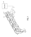
- FIG. 1 shows a back view of a printhead reservoir.
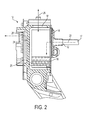
- FIG. 2 shows a cross-sectional view of one embodiment of a printhead reservoir.
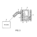
- FIG. 3 shows a cross-sectional view of an alternative embodiment of a printhead reservoir.
- Figure 1 shows an example of a printhead reservoir 10.
- the printhead reservoir includes at least one ink reservoir 16.
- the printhead reservoir serves to contain the ink used by the nozzles, or jets, that spray the ink onto a printing substrate.
- a print system may include a printer receiving data from a user for printing, a printer employed in a fax machine, a scanner or a copying machine. The description here implies no limitation on the use of a print system.
- the print system transfers ink to a printing substrate such as a piece of paper or other directly printed substrate, or an intermediate transfer surface.
- the jets receive ink from the ink reservoirs inside the printhead reservoir.
- An ink reservoir holds the ink later transported to the jets or nozzles that spray the ink on the printing substrate.
- the printhead reservoir may include external components bonded onto the plates that form the ink reservoir or reservoirs.
- the ink reservoirs form an internal component of the printhead reservoir.
- the printhead reservoir 10 in the example of Figure 1 has four ink reservoirs such as 16. This may occur in a color printer having a reservoir for each of the colors cyan, magenta, yellow and black. Each reservoir receives ink from an ink source 19. In one example, the ink source 19 provides ink through a pressurized, heated umbilical 17.
- the printhead reservoir 10 may have one or more connections or interfaces with the umbilical to secure the umbilical to the printhead reservoir for transfer of the ink.
- the printhead reservoir will filter the ink in some fashion to eliminate any particulates that may clog the jets or nozzles.
- the examples shown here use the filter 14 as a check valve. If the ink source 19 lies below the printhead reservoir in the print system, when the system removes the pressure used to transfer ink from the source 19 to the ink reservoir 16 the reservoir will drain back into the ink source. This lowers the efficiency and the speed of the print system, as the ink source will have to retransfer the ink back to the ink reservoir before printing can resume.
- the filter 14 eliminates or mitigates this problem. If the filter has sufficient meniscus strength, it acts as a check valve and prevents the ink from returning to the ink source. Once wetted with ink, the filter has a meniscus that must be overcome with pressure to cause air to flow through the filter in either direction.
- the ink source generally delivers the ink to the ink reservoirs under pressure, so nothing prevents the ink reservoir from receiving the ink. Without pressure in the reverse direction, however, the filter prevents the ink from draining out of the reservoir, since air cannot be pulled through it.
- Solid ink printhead generally need to have the air "purged" from the system, and may do so by applying pressure to the air vent 18. Without a check valve or an upstream filter above the ink in the reservoir, the ink would exit the umbilical. With this filter, if the purge pressure is lower than the filter bubble point, the meniscus will prevent this.
- 'draining' means that the ink reservoir loses at least a portion, if not all, of the ink in the reservoir.
- a reservoir may be partially drained or completely drained: the term 'drain' or 'draining' would include both.
- the reservoir will partially drain; in others the reservoir will completely drain, meaning that all ink in the reservoir returns to the ink source.
- 'all ink' takes into account that some residue of ink may remain in the reservoir or the umbilical.
- Figure 2 shows a cross-sectional view of one example of an ink reservoir within a printhead reservoir.
- the printhead reservoir 10 may contain more than one ink reservoir.
- the ink reservoir 16 receives ink from the ink source, not shown, from the umbilical 17 through the ink port or connection 12.
- the ink from the ink source travels along an input ink path 22.
- the reservoir holds the ink until the printhead activates and draws ink through a channel 20 along a jet path 24 to the exit to the jet 28.
- the filter 14 filters the ink from the source, and an air vent 18 allows air to vent from the reservoir 26 to avoid pressure buildup inside the reservoir.
- the ink when the pressure from the umbilical 17 falls off, the ink would drain out of the reservoir to the ink source without a check valve if the ink source resides in a position lower than the ink reservoir and the filter 14 resides below the ink level.
- the use of a filter above the ink level in the input ink path having sufficient meniscus strength alleviates this problem. Further, the position of the filter above a level of ink in the reservoir assists in preventing the reservoir from draining.
- the filter 14 consists of a stainless steel felt and mesh disc.
- the filter may be of any material that holds a strong enough meniscus, and may be of any shape.
- Figure 3 shows an alternative configuration of a printhead reservoir 10.
- a lack of space or flexibility in the system layout may dictate a position for the filter below the ink level.
- ink will fill the chamber in which the filter 14 resides.
- a weir plate 30 forms the chamber in which the filter resides.
- the pressure falls off, and the ink source 19 is below the ink reservoir 16, the amount of ink between the weir plate 30 and the ink reservoir 16 will siphon back into the umbilical 12.
- the ink will only partially drain in this instance, as the meniscus on the filter will hold an amount of ink corresponding to the amount of ink between the umbilical connection 12 and the filter 14.
- the filter discs may bond to the back plate of the printhead reservoir in various ways.
- Sylgard® bonds the stainless steel filter discs to the aluminum plate, allowing a strong mechanical connection.
- Sylgard® provides merely one example of a bonding agent or adhesive and does not limit the scope of the application in any way.
- the printhead reservoir plate may have a compartment or other feature to allow insertion of the filter without a bonding agent.
- a filter in the ink input path can act as a check valve. This eliminates the need for separate check valves, reducing the cost and complexity of the print system.
- the filter may reside above or under the ink level, allowing the filter to function as a check valve in different configurations.
- a filter as a check valve may have a broader application than just in print heads. Any fluid reservoir that employs a filter may benefit from moving the filter to an external position in order to use the filter as a check valve.
- the filter position should be in a fluid input path to the reservoir, rather than in an output fluid path.
Abstract
Description
- In an ink printer, a reservoir may hold the ink close to the nozzles or jets that deliver the ink to the print substrate such as a piece of paper. Ink is generally delivered to this reservoir via a port, and a delivery conduit of some type may feed ink to this port. For example, a solid ink printer in which the ink is melted prior to delivery to the reservoir uses a pressurized, heated umbilical to deliver melted ink to the reservoir. The ink source may reside in a position lower than the reservoir.
- Solid ink printheads generally have air bubbles in the ink after being warmed from a solid state. To remove this air, pressure may be applied to the system to "purge" a small amount of ink out that has air bubbles. For example, a solid ink printhead in which pressure is selectively applied to the ink reservoir via a vent port, downstream of the filter and ink delivery port.
- Without a check valve of some type, if a negative pressure is applied at the ink port, such as the ink source being lower than the ink reservoir, the ink will drain out of the reservoir when the pressure from the umbilical stops, and return to the ink source. The system must then `redeliver' the ink to the reservoir, slowing operation of the printer. In addition, if a positive pressure is applied to the reservoir downstream of the ink delivery port, the ink will drain or spray out of the reservoir. Unfortunately, check valves increase the cost and complexity of the printhead reservoir. This in turn increases the cost and complexity of the printing system, especially in color printers that may have several colors of ink and therefore several individual reservoirs in the printhead reservoir, and printers that may have several printheads.
- In one embodiment a printhead reservoir has at least one ink reservoir to hold ink, and at least one umbilical to deliver ink to the ink reservoir under pressure. A filter resides between the umbilical and the ink reservoir having meniscus strength, known in the industry as "bubble point", sufficient enough to prevent the reservoir from draining when the pressure is removed or when there is a positive pressure on the downstream side of the filter.
- The filter is typically positioned above a level of ink in the ink reservoir.
- Some examples of printhead reservoirs according to the invention will now be described with reference to the accompanying drawings, in which:-
-
FIG. 1 shows a back view of a printhead reservoir. -
FIG. 2 shows a cross-sectional view of one embodiment of a printhead reservoir. -
FIG. 3 shows a cross-sectional view of an alternative embodiment of a printhead reservoir. -
Figure 1 shows an example of aprinthead reservoir 10. The printhead reservoir, as that term is used here, includes at least oneink reservoir 16. In a print system, the printhead reservoir serves to contain the ink used by the nozzles, or jets, that spray the ink onto a printing substrate. A print system may include a printer receiving data from a user for printing, a printer employed in a fax machine, a scanner or a copying machine. The description here implies no limitation on the use of a print system. The print system transfers ink to a printing substrate such as a piece of paper or other directly printed substrate, or an intermediate transfer surface. The jets receive ink from the ink reservoirs inside the printhead reservoir. - An ink reservoir holds the ink later transported to the jets or nozzles that spray the ink on the printing substrate. In some instances, the printhead reservoir may include external components bonded onto the plates that form the ink reservoir or reservoirs. The ink reservoirs form an internal component of the printhead reservoir.
- The
printhead reservoir 10 in the example ofFigure 1 has four ink reservoirs such as 16. This may occur in a color printer having a reservoir for each of the colors cyan, magenta, yellow and black. Each reservoir receives ink from anink source 19. In one example, theink source 19 provides ink through a pressurized, heated umbilical 17. Theprinthead reservoir 10 may have one or more connections or interfaces with the umbilical to secure the umbilical to the printhead reservoir for transfer of the ink. - Generally, the printhead reservoir will filter the ink in some fashion to eliminate any particulates that may clog the jets or nozzles. The examples shown here use the
filter 14 as a check valve. If theink source 19 lies below the printhead reservoir in the print system, when the system removes the pressure used to transfer ink from thesource 19 to theink reservoir 16 the reservoir will drain back into the ink source. This lowers the efficiency and the speed of the print system, as the ink source will have to retransfer the ink back to the ink reservoir before printing can resume. - However, selection of the
filter 14 eliminates or mitigates this problem. If the filter has sufficient meniscus strength, it acts as a check valve and prevents the ink from returning to the ink source. Once wetted with ink, the filter has a meniscus that must be overcome with pressure to cause air to flow through the filter in either direction. The ink source generally delivers the ink to the ink reservoirs under pressure, so nothing prevents the ink reservoir from receiving the ink. Without pressure in the reverse direction, however, the filter prevents the ink from draining out of the reservoir, since air cannot be pulled through it. - Solid ink printhead generally need to have the air "purged" from the system, and may do so by applying pressure to the
air vent 18. Without a check valve or an upstream filter above the ink in the reservoir, the ink would exit the umbilical. With this filter, if the purge pressure is lower than the filter bubble point, the meniscus will prevent this. - The term 'draining' as used here means that the ink reservoir loses at least a portion, if not all, of the ink in the reservoir. A reservoir may be partially drained or completely drained: the term 'drain' or 'draining' would include both. In some cases, the reservoir will partially drain; in others the reservoir will completely drain, meaning that all ink in the reservoir returns to the ink source. Of course, 'all ink' takes into account that some residue of ink may remain in the reservoir or the umbilical.
-
Figure 2 shows a cross-sectional view of one example of an ink reservoir within a printhead reservoir. Theprinthead reservoir 10 may contain more than one ink reservoir. Theink reservoir 16 receives ink from the ink source, not shown, from the umbilical 17 through the ink port orconnection 12. The ink from the ink source travels along aninput ink path 22. The reservoir holds the ink until the printhead activates and draws ink through achannel 20 along ajet path 24 to the exit to thejet 28. Thefilter 14 filters the ink from the source, and anair vent 18 allows air to vent from thereservoir 26 to avoid pressure buildup inside the reservoir. - In this example, when the pressure from the umbilical 17 falls off, the ink would drain out of the reservoir to the ink source without a check valve if the ink source resides in a position lower than the ink reservoir and the
filter 14 resides below the ink level. The use of a filter above the ink level in the input ink path having sufficient meniscus strength alleviates this problem. Further, the position of the filter above a level of ink in the reservoir assists in preventing the reservoir from draining. - In one embodiment, the
filter 14 consists of a stainless steel felt and mesh disc. However, the filter may be of any material that holds a strong enough meniscus, and may be of any shape. -
Figure 3 shows an alternative configuration of aprinthead reservoir 10. In some print systems, a lack of space or flexibility in the system layout may dictate a position for the filter below the ink level. During pressurized ink delivery, ink will fill the chamber in which thefilter 14 resides. Aweir plate 30 forms the chamber in which the filter resides. When the pressure falls off, and theink source 19 is below theink reservoir 16, the amount of ink between theweir plate 30 and theink reservoir 16 will siphon back into the umbilical 12. The ink will only partially drain in this instance, as the meniscus on the filter will hold an amount of ink corresponding to the amount of ink between theumbilical connection 12 and thefilter 14. - Many other configurations may occur. Having a filter with a meniscus of a particular strength, such as about 15 in H2O prevents draining, at least in part, of the ink reservoir. This allows the print system to function more efficiently and generally with faster output. Many different kinds of filters may function in this environment. The filter discs may bond to the back plate of the printhead reservoir in various ways. In one example, Sylgard® bonds the stainless steel filter discs to the aluminum plate, allowing a strong mechanical connection. Sylgard® provides merely one example of a bonding agent or adhesive and does not limit the scope of the application in any way. In other examples, the printhead reservoir plate may have a compartment or other feature to allow insertion of the filter without a bonding agent.
- In this manner, a filter in the ink input path can act as a check valve. This eliminates the need for separate check valves, reducing the cost and complexity of the print system. The filter may reside above or under the ink level, allowing the filter to function as a check valve in different configurations.
- The use of a filter as a check valve may have a broader application than just in print heads. Any fluid reservoir that employs a filter may benefit from moving the filter to an external position in order to use the filter as a check valve. The filter position should be in a fluid input path to the reservoir, rather than in an output fluid path.
Claims (7)
- A printhead reservoir, comprising:at least one ink reservoir (16) to hold ink;at least one umbilical (17) to deliver ink to the ink reservoir under pressure; anda filter (14) between the umbilical and the ink reservoir having meniscus strength sufficient enough to prevent the reservoir from draining when the pressure is one of either removed or applied downstream of the filter.
- The printhead reservoir of claim 1, wherein the filter (14) comprises a disc filter.
- The printhead reservoir of claim 2, wherein the disc filter (14) comprises a disc of filter material bonded to a metal plate.
- The printhead reservoir of any of the preceding claims, further comprising a weir plate (30) in the ink reservoir.
- The printhead reservoir of any of the preceding claims, wherein the ink reservoir includes a hole (18) in a top of the reservoir to allow air to escape.
- The printhead reservoir of any of the preceding claims, the filter having a bubble point of approximately 15inH2O.
- A printhead reservoir according to any of the preceding claims, wherein the filter (14) is positioned above a level of ink in the ink reservoir.
Applications Claiming Priority (2)
| Application Number | Priority Date | Filing Date | Title |
|---|---|---|---|
| US11/563,294 US7748830B2 (en) | 2006-11-27 | 2006-11-27 | Printhead reservoir with filter external to jet fluid path |
| US11/564,538 US20080122901A1 (en) | 2006-11-29 | 2006-11-29 | Printhead reservoir with filter used as a check valve |
Publications (2)
| Publication Number | Publication Date |
|---|---|
| EP1925454A2 true EP1925454A2 (en) | 2008-05-28 |
| EP1925454A3 EP1925454A3 (en) | 2009-01-14 |
Family
ID=39154087
Family Applications (1)
| Application Number | Title | Priority Date | Filing Date |
|---|---|---|---|
| EP07121068A Withdrawn EP1925454A3 (en) | 2006-11-27 | 2007-11-20 | Printhead reservoir |
Country Status (1)
| Country | Link |
|---|---|
| EP (1) | EP1925454A3 (en) |
Citations (4)
| Publication number | Priority date | Publication date | Assignee | Title |
|---|---|---|---|---|
| US5409138A (en) * | 1992-09-22 | 1995-04-25 | Brother Kogyo Kabushiki Kaisha | Liquid supply device |
| JPH09187955A (en) * | 1995-11-08 | 1997-07-22 | Seiko Epson Corp | Ink-jet printer and ink cartridge used therein |
| US20020063764A1 (en) * | 2000-11-30 | 2002-05-30 | Kneezel Gary A. | Laser ablated filter |
| US20060201870A1 (en) * | 2005-03-10 | 2006-09-14 | Shinji Seto | Filter apparatus and droplet ejection device |
-
2007
- 2007-11-20 EP EP07121068A patent/EP1925454A3/en not_active Withdrawn
Patent Citations (4)
| Publication number | Priority date | Publication date | Assignee | Title |
|---|---|---|---|---|
| US5409138A (en) * | 1992-09-22 | 1995-04-25 | Brother Kogyo Kabushiki Kaisha | Liquid supply device |
| JPH09187955A (en) * | 1995-11-08 | 1997-07-22 | Seiko Epson Corp | Ink-jet printer and ink cartridge used therein |
| US20020063764A1 (en) * | 2000-11-30 | 2002-05-30 | Kneezel Gary A. | Laser ablated filter |
| US20060201870A1 (en) * | 2005-03-10 | 2006-09-14 | Shinji Seto | Filter apparatus and droplet ejection device |
Also Published As
| Publication number | Publication date |
|---|---|
| EP1925454A3 (en) | 2009-01-14 |
Similar Documents
| Publication | Publication Date | Title |
|---|---|---|
| US20080122901A1 (en) | Printhead reservoir with filter used as a check valve | |
| EP0908316B1 (en) | Ink jet printer | |
| JP5312365B2 (en) | Recycling waste phase change ink | |
| US8915579B2 (en) | Inkjet printing device and method for replacing a print head | |
| WO2006075314A3 (en) | Inkjet printer and method of controlling same | |
| JP2009528184A (en) | Printer with active fluid architecture | |
| JP4617799B2 (en) | Inkjet recording head maintenance method and inkjet recording apparatus | |
| JP2009279901A (en) | Liquid discharge apparatus and image projection apparatus | |
| EP2127885A1 (en) | Inkjet printing device | |
| US9132657B2 (en) | Ink supply apparatus and printing apparatus | |
| EP1925453A2 (en) | Printhead reservoir | |
| JP5402033B2 (en) | Image forming apparatus | |
| JP2005238761A (en) | Liquid channel member and liquid jet apparatus | |
| KR20100082168A (en) | Ink-jet printer providing suction function and operating method thereof | |
| JP2004009450A (en) | Ink jet recording apparatus | |
| EP1000748B1 (en) | Ink jet recording apparatus and cap for such apparatus | |
| EP1925454A2 (en) | Printhead reservoir | |
| US7380920B2 (en) | Ink jet apparatus | |
| JP2703647B2 (en) | Inkjet printer | |
| JP4256184B2 (en) | Liquid jet recording apparatus and ink filling method | |
| EP1424205B1 (en) | Ink jet recording apparatus | |
| US9266336B1 (en) | Ink barrier formed on printhead to prevent air intake | |
| JP2004050472A (en) | Inkjet recorder | |
| JP2703648B2 (en) | Inkjet printer | |
| JP7047587B2 (en) | Inkjet head and inkjet image forming equipment |
Legal Events
| Date | Code | Title | Description |
|---|---|---|---|
| PUAI | Public reference made under article 153(3) epc to a published international application that has entered the european phase |
Free format text: ORIGINAL CODE: 0009012 |
|
| AK | Designated contracting states |
Kind code of ref document: A2 Designated state(s): AT BE BG CH CY CZ DE DK EE ES FI FR GB GR HU IE IS IT LI LT LU LV MC MT NL PL PT RO SE SI SK TR |
|
| AX | Request for extension of the european patent |
Extension state: AL BA HR MK RS |
|
| PUAL | Search report despatched |
Free format text: ORIGINAL CODE: 0009013 |
|
| AK | Designated contracting states |
Kind code of ref document: A3 Designated state(s): AT BE BG CH CY CZ DE DK EE ES FI FR GB GR HU IE IS IT LI LT LU LV MC MT NL PL PT RO SE SI SK TR |
|
| AX | Request for extension of the european patent |
Extension state: AL BA HR MK RS |
|
| 17P | Request for examination filed |
Effective date: 20090714 |
|
| 17Q | First examination report despatched |
Effective date: 20090807 |
|
| AKX | Designation fees paid |
Designated state(s): DE FR GB |
|
| STAA | Information on the status of an ep patent application or granted ep patent |
Free format text: STATUS: THE APPLICATION IS DEEMED TO BE WITHDRAWN |
|
| 18D | Application deemed to be withdrawn |
Effective date: 20120601 |