EP1923952A1 - Received information transferring apparatus, receiver apparatus, and received information transferring system - Google Patents
Received information transferring apparatus, receiver apparatus, and received information transferring system Download PDFInfo
- Publication number
- EP1923952A1 EP1923952A1 EP06783227A EP06783227A EP1923952A1 EP 1923952 A1 EP1923952 A1 EP 1923952A1 EP 06783227 A EP06783227 A EP 06783227A EP 06783227 A EP06783227 A EP 06783227A EP 1923952 A1 EP1923952 A1 EP 1923952A1
- Authority
- EP
- European Patent Office
- Prior art keywords
- receiving
- unit
- receiving unit
- received information
- antenna
- Prior art date
- Legal status (The legal status is an assumption and is not a legal conclusion. Google has not performed a legal analysis and makes no representation as to the accuracy of the status listed.)
- Withdrawn
Links
Images




Classifications
-
- G—PHYSICS
- G06—COMPUTING OR CALCULATING; COUNTING
- G06F—ELECTRIC DIGITAL DATA PROCESSING
- G06F1/00—Details not covered by groups G06F3/00 - G06F13/00 and G06F21/00
- G06F1/16—Constructional details or arrangements
- G06F1/1613—Constructional details or arrangements for portable computers
- G06F1/1632—External expansion units, e.g. docking stations
-
- A—HUMAN NECESSITIES
- A61—MEDICAL OR VETERINARY SCIENCE; HYGIENE
- A61B—DIAGNOSIS; SURGERY; IDENTIFICATION
- A61B1/00—Instruments for performing medical examinations of the interior of cavities or tubes of the body by visual or photographical inspection, e.g. endoscopes; Illuminating arrangements therefor
- A61B1/00002—Operational features of endoscopes
- A61B1/00011—Operational features of endoscopes characterised by signal transmission
- A61B1/00016—Operational features of endoscopes characterised by signal transmission using wireless means
-
- A—HUMAN NECESSITIES
- A61—MEDICAL OR VETERINARY SCIENCE; HYGIENE
- A61B—DIAGNOSIS; SURGERY; IDENTIFICATION
- A61B1/00—Instruments for performing medical examinations of the interior of cavities or tubes of the body by visual or photographical inspection, e.g. endoscopes; Illuminating arrangements therefor
- A61B1/04—Instruments for performing medical examinations of the interior of cavities or tubes of the body by visual or photographical inspection, e.g. endoscopes; Illuminating arrangements therefor combined with photographic or television appliances
- A61B1/041—Capsule endoscopes for imaging
-
- A—HUMAN NECESSITIES
- A61—MEDICAL OR VETERINARY SCIENCE; HYGIENE
- A61B—DIAGNOSIS; SURGERY; IDENTIFICATION
- A61B5/00—Measuring for diagnostic purposes; Identification of persons
- A61B5/07—Endoradiosondes
- A61B5/073—Intestinal transmitters
-
- G—PHYSICS
- G06—COMPUTING OR CALCULATING; COUNTING
- G06F—ELECTRIC DIGITAL DATA PROCESSING
- G06F1/00—Details not covered by groups G06F3/00 - G06F13/00 and G06F21/00
- G06F1/16—Constructional details or arrangements
- G06F1/1613—Constructional details or arrangements for portable computers
- G06F1/163—Wearable computers, e.g. on a belt
-
- H—ELECTRICITY
- H01—ELECTRIC ELEMENTS
- H01Q—ANTENNAS, i.e. RADIO AERIALS
- H01Q1/00—Details of, or arrangements associated with, antennas
- H01Q1/27—Adaptation for use in or on movable bodies
- H01Q1/273—Adaptation for carrying or wearing by persons or animals
-
- H—ELECTRICITY
- H01—ELECTRIC ELEMENTS
- H01Q—ANTENNAS, i.e. RADIO AERIALS
- H01Q21/00—Antenna arrays or systems
- H01Q21/28—Combinations of substantially independent non-interacting antenna units or systems
-
- A—HUMAN NECESSITIES
- A61—MEDICAL OR VETERINARY SCIENCE; HYGIENE
- A61B—DIAGNOSIS; SURGERY; IDENTIFICATION
- A61B2560/00—Constructional details of operational features of apparatus; Accessories for medical measuring apparatus
- A61B2560/04—Constructional details of apparatus
- A61B2560/0456—Apparatus provided with a docking unit
-
- H—ELECTRICITY
- H04—ELECTRIC COMMUNICATION TECHNIQUE
- H04M—TELEPHONIC COMMUNICATION
- H04M1/00—Substation equipment, e.g. for use by subscribers
- H04M1/02—Constructional features of telephone sets
- H04M1/04—Supports for telephone transmitters or receivers
Definitions
- the present invention relates to a received information transferring apparatus, a receiving apparatus and a received information transferring system, and more particularly to a received information transferring apparatus capable of maintaining a received information transferring apparatus stably under connected state and a receiving apparatus connected to the received information transferring apparatus and a received information transferring system including the received information transferring apparatus and receiving apparatus.
- capsule endoscopes small endoscopes in pill shape for medical use
- capsule endoscope of this sort those incorporating in a capsule an illuminating unit composed of LED or the like, a solid-state imaging element composed of CCD, CMOS or the like, a transmitter for transmitting to the outside image data obtained by the solid-state imaging element, and a power supply unit composed of a battery or the like for driving these illuminating unit, solid-state imaging element and transmitter have been proposed (for example, see Patent Document 1).
- Patent Document Japanese Patent Application Laid-Open No. 2001-2311186
- the present invention has been developed in view of the foregoing, and an object of the present invention is to provide a received information transferring apparatus, a receiving apparatus and a received information transferring system which are stable under connected state.
- a received information transferring apparatus includes an engagement part for engaging with regard to a unit connection part which allows an antenna unit having at least a receiving antenna to be detachably connected to a receiving unit constituting a receiving apparatus together with the antenna unit; and a communication connector that is provided so as to be communicably connected to a connector provided to the receiving unit only when the unit connection part and the engagement part are in an engaged state.
- the engagement part is formed so as to be protruding to a portion where the antenna unit is mounted to the receiving unit, when the receiving unit is mounted to the received information transferring apparatus.
- the engagement part is formed such that a length from a lower end of the receiving unit to an upper end of the engagement part, in a state where the receiving unit is mounted to the received information transferring apparatus, becomes longer than a length from the lower end of the receiving unit to a lower end of a convey part provided to the antenna unit in a state where the antenna unit is mounted to the receiving unit, and when it is attempted to electrically connect the receiving apparatus, in the state where the antenna unit is mounted to the receiving unit, the upper end of the engagement part and the lower end of the convex part interfere with each other.
- a receiving apparatus includes an antenna unit to which a receiving antenna is connected and that executes a receiving processing of a radio signal received by the receiving antenna; and a receiving unit to which the antenna unit is detachably mounted and that executes various processings based on a received signal received by the antenna unit.
- the receiving unit can be electrically connected to a received information transferring apparatus via a connector of the receiving unit and a communication connector of the received information transferring apparatus, a convex part is provided to the antenna unit, the convex part is formed such that a length from a lower end of the receiving unit to a lower end of the convex part, in a state where the antenna unit is mounted to the receiving unit, is shorter than a length from the lower end of the receiving unit to an upper end of an engagement part provided on the received information transferring apparatus, in a state where the receiving unit is mounted to the received information transferring apparatus, and when it is attempted to electrically connect to the received information transferring apparatus, in the state where the antenna unit is mounted to the receiving unit, the upper end of the engagement part and the lower end of the convex part interfere with each other.
- a received information transferring system includes a receiving apparatus having an antenna unit to which a receiving antenna is connected and which executes a receiving processing of a radio signal received by the receiving antenna and a receiving unit to which the antenna unit is detachably connected and which executes various processings based on a received signal received by the antenna unit; and a received information transferring apparatus that can be electrically connected to the receiving unit via a connector of the receiving unit and a communication connector of the received information transferring apparatus.
- a convex part is provided to the antenna unit and an engagement part is provided to the receiving unit, the convex part and the engagement part are formed such that a length from a lower end of the receiving unit to an upper end of the engagement part, in a state where the receiving unit is mounted to the received information transferring apparatus, is longer than a length from the lower end of the receiving unit to a lower end of the convex part, in a state where the antenna unit is mounted to the receiving unit, and when it is attempted to electrically connect the receiving apparatus to the received information transferring apparatus, in the state where the antenna unit is mounted to the receiving unit, the upper end of the engagement part and the lower end of the convex part interfere with each other.
- a communication connector can be communicably connected to a connector provided to the receiving unit only when an engagement part for engaging with regard to a unit connection part which allows an antenna unit having at least a receiving antenna to be detachably connected to a receiving unit constituting a receiving apparatus together with the antenna unit is in engaged state with the unit connection part, it is possible to stabilize the received information transferring apparatus in connected state.
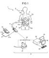
- FIG. 1 is a drawing showing an example of a whole composition of the capsule endoscope system including the cradle according to a first embodiment
- FIG. 2 is a perspective view showing the receiving antenna and receiving apparatus.
- a capsule endoscope system 1 primarily includes a capsule endoscope 2; receiving antennae 12a to 12h having loop antenna structure directly mounted by adhesion or the like to predetermined sites on the surface of a subject 3; a receiving apparatus 6 as a portable clinical equipment which is electrically connected to these receiving antennae 12 a to 12h by a cable 5 and records results of detection; and a workstation 8 provided at other than the subject 3.
- the subject 3 can swallow the capsule endoscope 2 which incorporates an imaging device; an illuminating device; a signal processor; a transmitter; and a power supply or the like (not shown).
- This capsule endoscope 2 swallowed by the subject 3 is introduced in the body cavity, takes images of imaging sites illuminated by the illuminating device such as LED or the like by the imaging device such as CCD, CMOS or the like to acquire pictorial images in the body cavity while it is moving in the body cavity lumen, converts the image data to a predetermined signal by the signal processor, and transmits the signal by the transmitter towards the receiving antennae 12a to 12h wirelessly.
- the receiving antennae 12a to 12h are to detect a signal of image data transmission output wirelessly from the transmitter in the capsule endoscope 2 as a predetermined electrical displacement, and are constituted by a plurality of loop antennae (eight in this example).
- Each of the antennae 12a to 12h is pasted directly or put into a bag or the like to the predetermined sites for example, right and left flank of abdomen of the subject 3, around epigastric fossa, right and left seventh rib, right and left hypogastric region or the like, using adhesive tape or the like.
- Eight cables 5 extending from these receiving antennae 12a to 12h are constituted by cables with good shielding performance, for example, coaxial cables.
- the length of these cables 5 each is determined in advance for each of corresponding receiving antennae 12a to 12h according to their positions on the body surface. Further, these cables 5 are aligned by a plurality of bundling members 13 so that eight cables may be lined up on the same plane on the way, as shown in FIG. 2 , and are pulled into an antenna unit 6b to be electrically connected to a receiving unit 6a of the receiving apparatus 6. Further, cables 5 are designed to be detachable from the antenna unit 6b.
- the receiving apparatus 6 includes the receiving unit 6a and the antenna unit 6b, and these are designed to be detachably attached.
- the receiving unit 6a includes a liquid crystal display unit 16; an antenna unit mounting part 17, a viewer cable connector 18, a connector 19 for connection with a cradle 27 which will be described later, or the like.
- a circuit member including CF memory for recording image data transmitted via the cable 5 is mounted on a substrate, and a battery pack with a capacity capable of coping with clinical examination continued for lengthy time as long as 8 to 10 hours is loaded in a battery chamber (not shown).
- the receiving unit 6a executes various processings on signals received by the receiving antennae 12a to 12h.
- the antenna unit mounting part 17 has such a composition that an internal circuit of the receiving unit 6a and the receiving antennae 12a to 12h are electrically connected, while the antenna unit 6b, which has removably attached connector construction, is inserted.
- Numeral 20 denotes an eject button for removing the antenna 6b.
- the viewer cable connector 18 is provided at side face of one side of the receiving unit 6a.
- the composition is such that if one connector 21a of the viewer cable 21 is attached to the viewer cable connector 18 and the other connector 21b to the viewer 22, images during clinical examination recorded by the receiving unit 6a can be checked by the viewer 22 as needed.
- the workstation 8 primarily has personal computers or the like installed in a hospital, and includes a display device 24, a printer 25, a keyboard 26 or the like, and further includes the cradle 27 for taking image data recorded in CF memory in the receiving unit 6a collectively into a workstation main body 23, and a cradle cable 28 such as USB cable or the like.
- the receiving unit 6a is inserted into the cradle 27 and is put into a state where it is electrically connected via the connector 19, the workstation main body 23 takes all image data recorded in CF memory in the receiving unit 6a collectively into the workstation main body 23.
- FIG. 3 is a perspective view of the cradle 27 according to the first embodiment
- FIG. 4 is a side elevation view of the cradle 27 according to the first embodiment.
- the cradle 27 according to the first embodiment is of stationary type and includes a concave part 30 at center portion thereof for placing the receiving unit 6a of the receiving apparatus 6, a connecting terminal 31 provided at bottom of the concave part 30, a backrest 32 for preventing falling of the receiving unit 6a when the receiving unit 6a is placed, and a protruding portion 33 provided at front edge of the backrest 32.
- FIG. 5 is a longitudinal sectional view showing a state where the receiving unit 6a is connected to the cradle 27.
- the antenna unit 6b is removed from the receiving unit 6a of the receiving apparatus 6 to obtain such a state that receiving antennae 12a to 12h and the receiving unit 6a are electrically separated.
- Lower end side (connector 19 side) of the receiving unit 6a which is now in such a state that the antenna unit 6b is removed, is then inserted into the concave part 30. This manipulation allows for engagement of the connector 19 of the receiving unit 6a and the connecting terminal 31 of the cradle 27, and the receiving unit 6a and the cradle 27 are electrically connected.
- the protruding portion 33 is protruding to a portion where the antenna unit 6a is mounted to the receiving unit 6a, as shown in FIG. 5 .
- the receiving apparatus 6 when it is attempted to connect the receiving apparatus 6 to the cradle 27 while the antenna unit 6b is mounted to the receiving unit 6a, as shown in FIG. 6 , the receiving apparatus 6 can not be inserted completely into the concave part 30, and the connector 19 is not engaged with the connecting terminal 31. This means that in a state where the antenna unit 6b is mounted to the receiving unit 6a, the receiving apparatus 6 and the cradle 27 are not electrically connected.
- the cradle 27 Since the cradle 27 according to the first embodiment has the protruding portion 33 for preventing the receiving apparatus 6 from being electrically connected, in a state where the antenna unit 6b is mounted to the receiving unit 6a, it is possible to prevent the receiving apparatus 6 from being connected to the cradle 27 while the receiving antennae 12a to 12h are connected, thereby maintaining the cradle stably in the connected state.
- a cradle 37 according to the second embodiment has no backrest 32, and shapes of the protruding portion 33 and protruding portion 43 are different. Further, constitution of the receiving apparatus 6 or the like are same as those according to the first embodiment, and therefore, like components are identified by the same reference numerals for explanation.
- FIG. 7 is a longitudinal sectional view showing a state where the receiving unit 6a is connected to the cradle 37.
- the cradle 37 according to the second embodiment has no backrest 32, and the protruding portion 43 is in a state protruding upwardly from rear side of the cradle 37.
- the connector 19 of the receiving unit 6a and the connecting terminal 31 of the cradle 37 are engaged, thereby electrically connecting the receiving unit 6a and the cradle 37.
- the protruding portion 43 is, as shown in FIG. 7 , protruding to a portion where the antenna unit 6b is mounted to the receiving unit 6a.
- the receiving apparatus 6 when it is attempted to connect the receiving apparatus 6 to the cradle 37 while the antenna unit 6b is mounted to the receiving unit 6a, as shown in FIG. 8 , as with the first embodiment, the receiving apparatus 6 can not be inserted completely into the concave part 30, and the connector 19 is not engaged with the connecting terminal 31. This means that in a state where the antenna unit 6b is mounted to the receiving unit 6a, the receiving apparatus 6 and the cradle 37 are not electrically connected.
- the cradle 37 according to the second embodiment has the protruding portion 43 for preventing the receiving apparatus 6 from being electrically connected, in a state where the antenna unit 6b is mounted to the receiving unit 6a, it is possible to prevent the receiving apparatus 6 from being connected to the cradle 27 while the receiving antennae 12a to 12h are connected, thereby maintaining the cradle stably in the connected state in similar fashion as the first embodiment.
- position, shape or the like of protruding portion to be provided to the cradle are not limited to above-mentioned ones as long as the receiving apparatus 6 is prevented from being electrically connected to the cradle in a state where the antenna unit 6b is mounted to the receiving unit 6a.
- FIG. 9 is a perspective view showing the receiving apparatus 46 according to the third embodiment.
- a receiving unit 46a of the receiving apparatus 46 is similar to the receiving unit 6a according to the first embodiment, an antenna unit 46b has a convex part 50 at both side faces, respectively.
- FIG. 10 is a front view showing a state when the receiving apparatus 46 is about to be connected to a cradle 57 according to the third embodiment under a state where the antenna unit 46b is mounted to the receiving unit 46a.
- the cradle 57 according to the third embodiment has two protruding portions 63 at both ends, and a concave part 60 is formed therebetween.
- the receiving unit 46a is inserted into the concave part 60 to height A to be electrically connected with the cradle 57.
- the connector 19 of the receiving unit 46a and a connecting terminal 61 of the cradle 57 are engaged.
- breadth of the receiving unit 46a and antenna unit 46b (excluding convex Part 50) according to the third embodiment, and breadth of the concave part 60 are set to be nearly identical.
- the receiving unit 46a and antenna unit 46b according to the embodiment are formed such that length L1 from lower end of the receiving unit 46a (height A) to upper end of a protruding portion 63 (height B), in a state where the receiving unit 46a is mounted to the cradle 57, is longer than length L2 from lower end of the receiving unit 46a (height C) to lower end of the convex part 50 (height C), in a state where the antenna unit 46b is mounted to the receiving unit 46a. For this reason, when it is attempted to connect the receiving apparatus 46 to the cradle 57 while the antenna unit 46b is mounted to the receiving unit 46a, upper end of the protruding portion 63 and lower end of the convex part 50 interfere with each other.
- the receiving apparatus 46 when it is attempted to connect the receiving apparatus 46 to the cradle 57 while the antenna unit 46b is mounted to the receiving unit 46a, as shown in FIG. 10 , as with the first embodiment, the receiving apparatus 46 can not be inserted completely into the concave part 60, and the connector 19 is not engaged with the connecting terminal 61. This means that in a state where the antenna unit 6b is mounted to the receiving unit 6a, the receiving apparatus 6 and the cradle 37 are not electrically connected.
- the antenna unit 46b has the convex part 50, and when it is attempted to connect the receiving apparatus 46 to the cradle 57 while the antenna unit 46b is mounted to the receiving unit 46a, upper end of the protruding portion 63 and lower end of the convex part 50 interfere with each other, and therefore, as with the first embodiment, it is possible to maintain stability of the cradle in connected state.
- position, shape or the like of the convex part 50 and protruding portion 63 are not limited to those exemplified in the third embodiment.
- the convex part 50 may be integrated to rear side of the antenna unit or the protruding portion 63 may be integrated to rear side of the cradle 57.
- the received information transferring apparatus, receiving apparatus and received information transferring system are useful for received information transferring apparatus, receiving apparatus and received information transferring system where connected state is maintained in stable fashion, and is particularly suited for received information transferring apparatus, receiving apparatus and received information transferring system in capsule endoscope system in which information transmitted from capsule endoscope is processed.
Landscapes
- Engineering & Computer Science (AREA)
- Health & Medical Sciences (AREA)
- Life Sciences & Earth Sciences (AREA)
- Physics & Mathematics (AREA)
- Surgery (AREA)
- Theoretical Computer Science (AREA)
- Pathology (AREA)
- Computer Hardware Design (AREA)
- Public Health (AREA)
- Veterinary Medicine (AREA)
- Biophysics (AREA)
- Biomedical Technology (AREA)
- Heart & Thoracic Surgery (AREA)
- Medical Informatics (AREA)
- Molecular Biology (AREA)
- Animal Behavior & Ethology (AREA)
- General Health & Medical Sciences (AREA)
- Optics & Photonics (AREA)
- Radiology & Medical Imaging (AREA)
- Nuclear Medicine, Radiotherapy & Molecular Imaging (AREA)
- Human Computer Interaction (AREA)
- General Engineering & Computer Science (AREA)
- General Physics & Mathematics (AREA)
- Computer Networks & Wireless Communication (AREA)
- Endoscopes (AREA)
- Support Of Aerials (AREA)
- Charge And Discharge Circuits For Batteries Or The Like (AREA)
- Secondary Cells (AREA)
- Telephone Set Structure (AREA)
- Telephone Function (AREA)
Abstract
Description
- The present invention relates to a received information transferring apparatus, a receiving apparatus and a received information transferring system, and more particularly to a received information transferring apparatus capable of maintaining a received information transferring apparatus stably under connected state and a receiving apparatus connected to the received information transferring apparatus and a received information transferring system including the received information transferring apparatus and receiving apparatus.
- In recent years, capsule endoscopes (swallowable endoscopes in pill shape for medical use) which can be introduced from the mouth into body cavity and are designed to acquire information in the living body cavity through imaging or the like inside of digestive organs such as stomach or the like have been developed. As capsule endoscope of this sort, those incorporating in a capsule an illuminating unit composed of LED or the like, a solid-state imaging element composed of CCD, CMOS or the like, a transmitter for transmitting to the outside image data obtained by the solid-state imaging element, and a power supply unit composed of a battery or the like for driving these illuminating unit, solid-state imaging element and transmitter have been proposed (for example, see Patent Document 1).
- When performing clinical examination using a capsule endoscope, electric wave transmitted by a capsule swallowed by a subject is caught by receiving antennae pasted at more than one portion, for example, eight portions, on the surface of the subject body, data thus caught are sent to a receiving apparatus via antenna cable, and is recorded by the receiving apparatus into CF memory or the like. Although it takes, for example, 8 to 10 hours until the clinical examination is completed, the subject is able to continue normal life while equipped with the receiving antennae and receiving apparatus. Upon completion of measurements by the capsule endoscope, the subject submits the receiving apparatus or the like to the hospital, hospital side then plugs the receiving apparatus into a cradle, and all measurement data recorded in the receiving apparatus are taken in a workstation which is connected to the cradle via USB cable. Following this, measurement results are observed as moving images on the workstation.
- Patent Document: Japanese Patent Application Laid-Open No.
2001-2311186 - However, there is such a problem that if a receiving apparatus is plugged into a cradle while receiving antennae are connected, the cradle becomes unstable and the receiving apparatus is disengaged from the cradle while recorded measurement data are taken from the receiving apparatus to the workstation.
- The present invention has been developed in view of the foregoing, and an object of the present invention is to provide a received information transferring apparatus, a receiving apparatus and a received information transferring system which are stable under connected state.
- In order to solve above-mentioned problem and to accomplish the object, a received information transferring apparatus according to the present invention includes an engagement part for engaging with regard to a unit connection part which allows an antenna unit having at least a receiving antenna to be detachably connected to a receiving unit constituting a receiving apparatus together with the antenna unit; and a communication connector that is provided so as to be communicably connected to a connector provided to the receiving unit only when the unit connection part and the engagement part are in an engaged state.
- Further, in the received information transferring apparatus according to the present invention, the engagement part is formed so as to be protruding to a portion where the antenna unit is mounted to the receiving unit, when the receiving unit is mounted to the received information transferring apparatus.
- Further, in the received information transferring apparatus according to the present invention, the engagement part is formed such that a length from a lower end of the receiving unit to an upper end of the engagement part, in a state where the receiving unit is mounted to the received information transferring apparatus, becomes longer than a length from the lower end of the receiving unit to a lower end of a convey part provided to the antenna unit in a state where the antenna unit is mounted to the receiving unit, and when it is attempted to electrically connect the receiving apparatus, in the state where the antenna unit is mounted to the receiving unit, the upper end of the engagement part and the lower end of the convex part interfere with each other.
- A receiving apparatus according to the present invention includes an antenna unit to which a receiving antenna is connected and that executes a receiving processing of a radio signal received by the receiving antenna; and a receiving unit to which the antenna unit is detachably mounted and that executes various processings based on a received signal received by the antenna unit. In the receiving apparatus, the receiving unit can be electrically connected to a received information transferring apparatus via a connector of the receiving unit and a communication connector of the received information transferring apparatus, a convex part is provided to the antenna unit, the convex part is formed such that a length from a lower end of the receiving unit to a lower end of the convex part, in a state where the antenna unit is mounted to the receiving unit, is shorter than a length from the lower end of the receiving unit to an upper end of an engagement part provided on the received information transferring apparatus, in a state where the receiving unit is mounted to the received information transferring apparatus, and when it is attempted to electrically connect to the received information transferring apparatus, in the state where the antenna unit is mounted to the receiving unit, the upper end of the engagement part and the lower end of the convex part interfere with each other.
- A received information transferring system according to the present invention includes a receiving apparatus having an antenna unit to which a receiving antenna is connected and which executes a receiving processing of a radio signal received by the receiving antenna and a receiving unit to which the antenna unit is detachably connected and which executes various processings based on a received signal received by the antenna unit; and a received information transferring apparatus that can be electrically connected to the receiving unit via a connector of the receiving unit and a communication connector of the received information transferring apparatus. In the received information transferring system, a convex part is provided to the antenna unit and an engagement part is provided to the receiving unit, the convex part and the engagement part are formed such that a length from a lower end of the receiving unit to an upper end of the engagement part, in a state where the receiving unit is mounted to the received information transferring apparatus, is longer than a length from the lower end of the receiving unit to a lower end of the convex part, in a state where the antenna unit is mounted to the receiving unit, and when it is attempted to electrically connect the receiving apparatus to the received information transferring apparatus, in the state where the antenna unit is mounted to the receiving unit, the upper end of the engagement part and the lower end of the convex part interfere with each other.
- In the received information transferring apparatus, receiving apparatus and received information transferring system according to the present invention, since a communication connector can be communicably connected to a connector provided to the receiving unit only when an engagement part for engaging with regard to a unit connection part which allows an antenna unit having at least a receiving antenna to be detachably connected to a receiving unit constituting a receiving apparatus together with the antenna unit is in engaged state with the unit connection part, it is possible to stabilize the received information transferring apparatus in connected state.
-
-
FIG. 1 is a diagram showing an example of a whole composition of a capsule endoscope system including a cradle according to a first embodiment; -
FIG. 2 is a perspective view showing a receiving antenna and receiving apparatus according to the first embodiment; -
FIG. 3 is a perspective view of the cradle according to the first embodiment. -
FIG. 4 is a side elevation view of the cradle according to the first embodiment; -
FIG. 5 is a longitudinal sectional view showing a state where a receiving unit is connected to the cradle; -
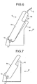
FIG. 6 is a longitudinal sectional view showing a state when the receiving apparatus is about to be connected to the cradle under a state where an antenna unit is mounted to the receiving unit; -
FIG. 7 is a longitudinal sectional view showing a state where the receiving unit according to a second embodiment is connected to the cradle; -
FIG. 8 is a longitudinal sectional view showing a state when the receiving apparatus is about to be connected to the cradle under a state where the antenna unit is mounted to the receiving unit; -
FIG. 9 is a perspective view showing the receiving apparatus according to a third embodiment; and -
FIG. 10 is a front view showing a state when the receiving apparatus is about to be connected to the cradle according to the third embodiment under a state where the antenna unit is mounted to the receiving unit. -
- 1
- Capsule endoscope system
- 2
- Capsule endoscope
- 3
- Subject
- 5
- Cable
- 6, 46
- Receiving apparatus
- 6a, 46a
- Receiving unit
- 6b, 46b
- Antenna unit
- 8
- Workstation
- 12a, 12b, 12c, 12d, 12e, 12f, 12g, 12h
- Receiving antennae
- 16
- Liquid crystal display unit
- 17
- Antenna unit mounting part
- 18
- Viewer cable connector
- 19
- Connector
- 20
- Eject button
- 21
- Viewer cable
- 22
- Viewer
- 23
- Workstation main body
- 24
- Display device
- 25
- Printer
- 26
- Keyboard
- 27, 37, 57
- Cradle
- 28
- Cradle cable
- 30, 60
- Concave part
- 31, 61
- Connecting terminal
- 7
- Backrest
- 33,43,63
- Protruding portion
- 50
- Convex part
- Referring now to the drawings, embodiments of the received information transferring apparatus (cradle), receiving apparatus, and received information transferring system (cradle system) of the present invention will be explained hereafter. In the embodiments shown below, an example where the cradle, receiving apparatus, and cradle system of the present invention are applied to the capsule endoscope system is shown. However, the present invention is in no way restricted by such specific embodiments.
-
FIG. 1 is a drawing showing an example of a whole composition of the capsule endoscope system including the cradle according to a first embodiment, andFIG. 2 is a perspective view showing the receiving antenna and receiving apparatus. A capsule endoscope system 1 primarily includes acapsule endoscope 2; receivingantennae 12a to 12h having loop antenna structure directly mounted by adhesion or the like to predetermined sites on the surface of a subject 3; a receivingapparatus 6 as a portable clinical equipment which is electrically connected to these receivingantennae 12 a to 12h by acable 5 and records results of detection; and aworkstation 8 provided at other than thesubject 3. - It is possible for the subject 3 to swallow the
capsule endoscope 2 which incorporates an imaging device; an illuminating device; a signal processor; a transmitter; and a power supply or the like (not shown). Thiscapsule endoscope 2 swallowed by thesubject 3 is introduced in the body cavity, takes images of imaging sites illuminated by the illuminating device such as LED or the like by the imaging device such as CCD, CMOS or the like to acquire pictorial images in the body cavity while it is moving in the body cavity lumen, converts the image data to a predetermined signal by the signal processor, and transmits the signal by the transmitter towards the receivingantennae 12a to 12h wirelessly. - Further, the receiving
antennae 12a to 12h are to detect a signal of image data transmission output wirelessly from the transmitter in thecapsule endoscope 2 as a predetermined electrical displacement, and are constituted by a plurality of loop antennae (eight in this example). Each of theantennae 12a to 12h is pasted directly or put into a bag or the like to the predetermined sites for example, right and left flank of abdomen of the subject 3, around epigastric fossa, right and left seventh rib, right and left hypogastric region or the like, using adhesive tape or the like. - Eight
cables 5 extending from these receivingantennae 12a to 12h are constituted by cables with good shielding performance, for example, coaxial cables. The length of thesecables 5 each is determined in advance for each of corresponding receivingantennae 12a to 12h according to their positions on the body surface. Further, thesecables 5 are aligned by a plurality of bundlingmembers 13 so that eight cables may be lined up on the same plane on the way, as shown inFIG. 2 , and are pulled into anantenna unit 6b to be electrically connected to a receivingunit 6a of the receivingapparatus 6. Further,cables 5 are designed to be detachable from theantenna unit 6b. - The receiving
apparatus 6 includes the receivingunit 6a and theantenna unit 6b, and these are designed to be detachably attached. As shown inFIG. 2 , the receivingunit 6a includes a liquidcrystal display unit 16; an antennaunit mounting part 17, aviewer cable connector 18, aconnector 19 for connection with acradle 27 which will be described later, or the like. Inside the receivingunit 6a, a circuit member including CF memory for recording image data transmitted via thecable 5 is mounted on a substrate, and a battery pack with a capacity capable of coping with clinical examination continued for lengthy time as long as 8 to 10 hours is loaded in a battery chamber (not shown). In addition to recording of the image data, the receivingunit 6a executes various processings on signals received by the receivingantennae 12a to 12h. The antennaunit mounting part 17 has such a composition that an internal circuit of the receivingunit 6a and the receivingantennae 12a to 12h are electrically connected, while theantenna unit 6b, which has removably attached connector construction, is inserted.Numeral 20 denotes an eject button for removing theantenna 6b. - The
viewer cable connector 18 is provided at side face of one side of the receivingunit 6a. The composition is such that if oneconnector 21a of the viewer cable 21 is attached to theviewer cable connector 18 and theother connector 21b to theviewer 22, images during clinical examination recorded by the receivingunit 6a can be checked by theviewer 22 as needed. - Besides, the
workstation 8 primarily has personal computers or the like installed in a hospital, and includes adisplay device 24, aprinter 25, akeyboard 26 or the like, and further includes thecradle 27 for taking image data recorded in CF memory in the receivingunit 6a collectively into a workstationmain body 23, and acradle cable 28 such as USB cable or the like. When the receivingunit 6a is inserted into thecradle 27 and is put into a state where it is electrically connected via theconnector 19, the workstationmain body 23 takes all image data recorded in CF memory in the receivingunit 6a collectively into the workstationmain body 23. - Next, the
cradle 27 according to the first embodiment will be explained.FIG. 3 is a perspective view of thecradle 27 according to the first embodiment, andFIG. 4 is a side elevation view of thecradle 27 according to the first embodiment. Thecradle 27 according to the first embodiment is of stationary type and includes aconcave part 30 at center portion thereof for placing the receivingunit 6a of the receivingapparatus 6, a connectingterminal 31 provided at bottom of theconcave part 30, abackrest 32 for preventing falling of the receivingunit 6a when the receivingunit 6a is placed, and a protrudingportion 33 provided at front edge of thebackrest 32. - Now, a method for connecting the receiving
unit 6a to thecradle 27 will be explained hereafter.FIG. 5 is a longitudinal sectional view showing a state where the receivingunit 6a is connected to thecradle 27. First, theantenna unit 6b is removed from the receivingunit 6a of the receivingapparatus 6 to obtain such a state that receivingantennae 12a to 12h and the receivingunit 6a are electrically separated. Lower end side (connector 19 side) of the receivingunit 6a, which is now in such a state that theantenna unit 6b is removed, is then inserted into theconcave part 30. This manipulation allows for engagement of theconnector 19 of the receivingunit 6a and the connectingterminal 31 of thecradle 27, and the receivingunit 6a and thecradle 27 are electrically connected. - In a state where the receiving
unit 6a is inserted into theconcave part 30 of thecradle 27, and the receivingunit 6a and thecradle 27 are electrically connected, the protrudingportion 33 is protruding to a portion where theantenna unit 6a is mounted to the receivingunit 6a, as shown inFIG. 5 . - Therefore, when it is attempted to connect the receiving
apparatus 6 to thecradle 27 while theantenna unit 6b is mounted to the receivingunit 6a, as shown inFIG. 6 , the receivingapparatus 6 can not be inserted completely into theconcave part 30, and theconnector 19 is not engaged with the connectingterminal 31. This means that in a state where theantenna unit 6b is mounted to the receivingunit 6a, the receivingapparatus 6 and thecradle 27 are not electrically connected. - Since the
cradle 27 according to the first embodiment has the protrudingportion 33 for preventing the receivingapparatus 6 from being electrically connected, in a state where theantenna unit 6b is mounted to the receivingunit 6a, it is possible to prevent the receivingapparatus 6 from being connected to thecradle 27 while the receivingantennae 12a to 12h are connected, thereby maintaining the cradle stably in the connected state. - Next, a second embodiment will be explained. Compared with the
cradle 27 according to the first embodiment, acradle 37 according to the second embodiment has nobackrest 32, and shapes of the protrudingportion 33 and protrudingportion 43 are different. Further, constitution of the receivingapparatus 6 or the like are same as those according to the first embodiment, and therefore, like components are identified by the same reference numerals for explanation. -
FIG. 7 is a longitudinal sectional view showing a state where the receivingunit 6a is connected to thecradle 37. Thecradle 37 according to the second embodiment has nobackrest 32, and the protrudingportion 43 is in a state protruding upwardly from rear side of thecradle 37. As with the first embodiment, when lower end side (connector 19 side) of the receivingunit 6a, from which theantenna unit 6b is removed, is inserted into theconcave part 30, theconnector 19 of the receivingunit 6a and the connectingterminal 31 of thecradle 37 are engaged, thereby electrically connecting the receivingunit 6a and thecradle 37. - In a state where the receiving
unit 6a is inserted into theconcave part 30 of thecradle 37, and the receivingunit 6a and thecradle 37 are electrically connected, the protrudingportion 43 is, as shown inFIG. 7 , protruding to a portion where theantenna unit 6b is mounted to the receivingunit 6a. - Further, when it is attempted to connect the receiving
apparatus 6 to thecradle 37 while theantenna unit 6b is mounted to the receivingunit 6a, as shown inFIG. 8 , as with the first embodiment, the receivingapparatus 6 can not be inserted completely into theconcave part 30, and theconnector 19 is not engaged with the connectingterminal 31. This means that in a state where theantenna unit 6b is mounted to the receivingunit 6a, the receivingapparatus 6 and thecradle 37 are not electrically connected. - Since the
cradle 37 according to the second embodiment has the protrudingportion 43 for preventing the receivingapparatus 6 from being electrically connected, in a state where theantenna unit 6b is mounted to the receivingunit 6a, it is possible to prevent the receivingapparatus 6 from being connected to thecradle 27 while the receivingantennae 12a to 12h are connected, thereby maintaining the cradle stably in the connected state in similar fashion as the first embodiment. Meanwhile, position, shape or the like of protruding portion to be provided to the cradle are not limited to above-mentioned ones as long as the receivingapparatus 6 is prevented from being electrically connected to the cradle in a state where theantenna unit 6b is mounted to the receivingunit 6a. - Next, a cradle, receiving apparatus and cradle system including this cradle and receiving apparatus according to a third embodiment will be explained. Meanwhile, components similar to those of the first embodiment are identified by the same reference numerals for explanation.
FIG. 9 is a perspective view showing the receivingapparatus 46 according to the third embodiment. Although a receivingunit 46a of the receivingapparatus 46 is similar to the receivingunit 6a according to the first embodiment, anantenna unit 46b has aconvex part 50 at both side faces, respectively. -
FIG. 10 is a front view showing a state when the receivingapparatus 46 is about to be connected to acradle 57 according to the third embodiment under a state where theantenna unit 46b is mounted to the receivingunit 46a. Thecradle 57 according to the third embodiment has two protrudingportions 63 at both ends, and aconcave part 60 is formed therebetween. In a state where theantenna unit 46b is removed, the receivingunit 46a is inserted into theconcave part 60 to height A to be electrically connected with thecradle 57. On this occasion, theconnector 19 of the receivingunit 46a and a connectingterminal 61 of thecradle 57 are engaged. In the meantime, breadth of the receivingunit 46a andantenna unit 46b (excluding convex Part 50) according to the third embodiment, and breadth of theconcave part 60 are set to be nearly identical. - The receiving
unit 46a andantenna unit 46b according to the embodiment are formed such that length L1 from lower end of the receivingunit 46a (height A) to upper end of a protruding portion 63 (height B), in a state where the receivingunit 46a is mounted to thecradle 57, is longer than length L2 from lower end of the receivingunit 46a (height C) to lower end of the convex part 50 (height C), in a state where theantenna unit 46b is mounted to the receivingunit 46a. For this reason, when it is attempted to connect the receivingapparatus 46 to thecradle 57 while theantenna unit 46b is mounted to the receivingunit 46a, upper end of the protrudingportion 63 and lower end of theconvex part 50 interfere with each other. - Accordingly, when it is attempted to connect the receiving
apparatus 46 to thecradle 57 while theantenna unit 46b is mounted to the receivingunit 46a, as shown inFIG. 10 , as with the first embodiment, the receivingapparatus 46 can not be inserted completely into theconcave part 60, and theconnector 19 is not engaged with the connectingterminal 61. This means that in a state where theantenna unit 6b is mounted to the receivingunit 6a, the receivingapparatus 6 and thecradle 37 are not electrically connected. - With the cradle system according to the third embodiment, the
antenna unit 46b has theconvex part 50, and when it is attempted to connect the receivingapparatus 46 to thecradle 57 while theantenna unit 46b is mounted to the receivingunit 46a, upper end of the protrudingportion 63 and lower end of theconvex part 50 interfere with each other, and therefore, as with the first embodiment, it is possible to maintain stability of the cradle in connected state. Meanwhile, position, shape or the like of theconvex part 50 and protrudingportion 63 are not limited to those exemplified in the third embodiment. For example, theconvex part 50 may be integrated to rear side of the antenna unit or the protrudingportion 63 may be integrated to rear side of thecradle 57. - As mentioned above, the received information transferring apparatus, receiving apparatus and received information transferring system according to the present invention are useful for received information transferring apparatus, receiving apparatus and received information transferring system where connected state is maintained in stable fashion, and is particularly suited for received information transferring apparatus, receiving apparatus and received information transferring system in capsule endoscope system in which information transmitted from capsule endoscope is processed.
Claims (5)
- A received information transferring apparatus, comprising:an engagement part for engaging with regard to a unit connection part which allows an antenna unit having at least a receiving antenna to be detachably connected to a receiving unit constituting a receiving apparatus together with the antenna unit; anda communication connector that is provided so as to be communicably connected to a connector provided to the receiving unit only when the unit connection part and the engagement part are in an engaged state.
- The received information transferring apparatus according to claim 1, wherein the engagement part is formed so as to be protruding to a portion where the antenna unit is mounted to the receiving unit, when the receiving unit is mounted to the received information transferring apparatus.
- The received information transferring apparatus according to claim 1, wherein the engagement part is formed such that a length from a lower end of the receiving unit to an upper end of the engagement part, in a state where the receiving unit is mounted to the received information transferring apparatus, becomes longer than a length from the lower end of the receiving unit to a lower end of a convex part provided to the antenna unit, in a state where the antenna unit is mounted to the receiving unit, and when it is attempted to electrically connect the receiving apparatus, in the state where the antenna unit is mounted to the receiving unit, the upper end of the engagement part and the lower end of the convex part interfere with each other.
- A receiving apparatus, comprising:an antenna unit to which a receiving antenna is connected and that executes a receiving processing of a radio signal received by the receiving antenna; anda receiving unit to which the antenna unit is detachably mounted and that executes various processings based on a received signal received by the antenna unit,wherein the receiving unit can be electrically connected to a received information transferring apparatus via a connector of the receiving unit and a communication connector of the received information transferring apparatus, and
wherein a convex part is provided to the antenna unit, the convex part is formed such that a length from a lower end of the receiving unit to a lower end of the convex part, in a state where the antenna unit is mounted to the receiving unit, is shorter than a length from the lower end of the receiving unit to an upper end of an engagement part provided on the received information transferring apparatus, in a state where the receiving unit is mounted to the received information transferring apparatus, and when it is attempted to electrically connect to the received information transferring apparatus, in the state where the antenna unit is mounted to the receiving unit, the upper end of the engagement part and the lower end of the convex part interfere with each other. - A received information transferring system, comprising:a receiving apparatus having an antenna unit to which a receiving antenna is connected and which executes a receiving processing of a radio signal received by the receiving antenna and a receiving unit to which the antenna unit is detachably connected and which executes various processings based on a received signal received by the antenna unit; anda received information transferring apparatus that can be electrically connected to the receiving unit via a connector of the receiving unit and a communication connector of the received information transferring apparatus,wherein a convex part is provided to the antenna unit and an engagement part is provided to the receiving unit, and
wherein the convex part and the engagement part are formed such that a length from a lower end of the receiving unit to an upper end of the engagement part, in a state where the receiving unit is mounted to the received information transferring apparatus, is longer than a length from the lower end of the receiving unit to a lower end of the convex part, in a state where the antenna unit is mounted to the receiving unit, and when it is attempted to electrically connect the receiving apparatus to the received information transferring apparatus, in the state where the antenna unit is mounted to the receiving unit, the upper end of the engagement part and the lower end of the convex part interfere with each other.
Applications Claiming Priority (2)
| Application Number | Priority Date | Filing Date | Title |
|---|---|---|---|
| JP2005263114A JP4350691B2 (en) | 2005-09-09 | 2005-09-09 | Reception information transfer device, reception device, and reception information transfer system |
| PCT/JP2006/317867 WO2007029817A1 (en) | 2005-09-09 | 2006-09-08 | Received information transferring apparatus, receiver apparatus, and received information transferring system |
Publications (2)
| Publication Number | Publication Date |
|---|---|
| EP1923952A1 true EP1923952A1 (en) | 2008-05-21 |
| EP1923952A4 EP1923952A4 (en) | 2010-01-27 |
Family
ID=37835932
Family Applications (1)
| Application Number | Title | Priority Date | Filing Date |
|---|---|---|---|
| EP06783227A Withdrawn EP1923952A4 (en) | 2005-09-09 | 2006-09-08 | APPARATUS FOR TRANSFERRING RECEIVED INFORMATION, RECEIVER APPARATUS AND INFORMATION TRANSFER SYSTEM RECEIVED |
Country Status (6)
| Country | Link |
|---|---|
| US (1) | US7843329B2 (en) |
| EP (1) | EP1923952A4 (en) |
| JP (1) | JP4350691B2 (en) |
| CN (1) | CN101243578B (en) |
| AU (1) | AU2006288210B2 (en) |
| WO (1) | WO2007029817A1 (en) |
Cited By (2)
| Publication number | Priority date | Publication date | Assignee | Title |
|---|---|---|---|---|
| WO2020148280A3 (en) * | 2019-01-14 | 2020-08-27 | Analog Devices International Unlimited Company | Multi-sensor device for monitoring health |
| US12702319B2 (en) | 2017-01-24 | 2026-08-11 | Analog Devices, Inc. | Multi-sensor device for monitoring health |
Families Citing this family (8)
| Publication number | Priority date | Publication date | Assignee | Title |
|---|---|---|---|---|
| JP4956287B2 (en) * | 2007-06-06 | 2012-06-20 | オリンパスメディカルシステムズ株式会社 | Capsule endoscope system and program |
| US8113873B1 (en) | 2009-09-22 | 2012-02-14 | Western Digital Technologies, Inc. | Pivot assisted storage device unloading mechanism |
| WO2012073761A1 (en) * | 2010-11-29 | 2012-06-07 | オリンパスメディカルシステムズ株式会社 | Transmitter-receiver device, antenna unit and system to be introduced into subject |
| EP2541368B1 (en) * | 2011-06-30 | 2016-09-14 | BlackBerry Limited | Dock for a portable electronic device |
| CN110448264A (en) * | 2018-05-07 | 2019-11-15 | 上海法路源医疗器械有限公司 | A kind of pedestal and electronics examination per vagina system |
| US11606111B2 (en) | 2021-05-26 | 2023-03-14 | Getac Technology Corporation | Adaptive power and communication routing for body-worn devices |
| US11808823B2 (en) * | 2021-06-02 | 2023-11-07 | Getac Technology Corporation | Detection of device dislocation using power and non-powered dislocation sensors |
| US11864271B2 (en) | 2021-09-21 | 2024-01-02 | Getac Technology Corporation | Mobile device ID tracking for automatic incident data association and correlation |
Family Cites Families (11)
| Publication number | Priority date | Publication date | Assignee | Title |
|---|---|---|---|---|
| US5959287A (en) * | 1997-04-23 | 1999-09-28 | Lxe Inc. | Apparatus and method for supporting a cradle |
| JP4080662B2 (en) | 2000-02-15 | 2008-04-23 | ペンタックス株式会社 | Power transmission system |
| US6864798B2 (en) * | 2000-08-02 | 2005-03-08 | Simple Devices | Device docking apparatus and method for using the same |
| JP2002198789A (en) | 2000-12-25 | 2002-07-12 | Ando Electric Co Ltd | Signal cutoff circuit and signal selection circuit |
| JP3974769B2 (en) | 2001-11-06 | 2007-09-12 | オリンパス株式会社 | Capsule medical device |
| JP2003195730A (en) | 2001-12-28 | 2003-07-09 | Canon Inc | Cover member, unit of image forming apparatus, developing cartridge, shutter member, process cartridge, and image forming apparatus |
| JP2004213841A (en) | 2003-01-08 | 2004-07-29 | Sony Corp | Hard disk system, hard disk unit, conversion unit |
| JP2004227071A (en) | 2003-01-20 | 2004-08-12 | Olympus Corp | Information terminal device system |
| KR100503479B1 (en) * | 2003-01-24 | 2005-07-28 | 삼성전자주식회사 | a cradle of portable terminal and locking method of portable terminal using thereof |
| JP4455067B2 (en) | 2004-01-14 | 2010-04-21 | オリンパス株式会社 | Capsule endoscope device |
| JP4102319B2 (en) | 2004-03-03 | 2008-06-18 | オリンパス株式会社 | Specimen inspection device |
-
2005
- 2005-09-09 JP JP2005263114A patent/JP4350691B2/en not_active Expired - Fee Related
-
2006
- 2006-09-08 EP EP06783227A patent/EP1923952A4/en not_active Withdrawn
- 2006-09-08 US US11/576,988 patent/US7843329B2/en active Active
- 2006-09-08 CN CN200680030369.0A patent/CN101243578B/en not_active Expired - Fee Related
- 2006-09-08 AU AU2006288210A patent/AU2006288210B2/en not_active Ceased
- 2006-09-08 WO PCT/JP2006/317867 patent/WO2007029817A1/en not_active Ceased
Non-Patent Citations (2)
| Title |
|---|
| No further relevant documents disclosed * |
| See also references of WO2007029817A1 * |
Cited By (3)
| Publication number | Priority date | Publication date | Assignee | Title |
|---|---|---|---|---|
| US12702319B2 (en) | 2017-01-24 | 2026-08-11 | Analog Devices, Inc. | Multi-sensor device for monitoring health |
| WO2020148280A3 (en) * | 2019-01-14 | 2020-08-27 | Analog Devices International Unlimited Company | Multi-sensor device for monitoring health |
| US12599354B2 (en) | 2019-01-14 | 2026-04-14 | Analog Devices International Unlimited Company | Multi-sensor device for monitoring health |
Also Published As
| Publication number | Publication date |
|---|---|
| AU2006288210A1 (en) | 2007-03-15 |
| JP2007081492A (en) | 2007-03-29 |
| CN101243578B (en) | 2013-06-12 |
| JP4350691B2 (en) | 2009-10-21 |
| AU2006288210B2 (en) | 2010-04-01 |
| CN101243578A (en) | 2008-08-13 |
| US7843329B2 (en) | 2010-11-30 |
| EP1923952A4 (en) | 2010-01-27 |
| WO2007029817A1 (en) | 2007-03-15 |
| US20080304240A1 (en) | 2008-12-11 |
Similar Documents
| Publication | Publication Date | Title |
|---|---|---|
| EP2106737B1 (en) | Antenna unit and receiving apparatus for capsule medical apparatus | |
| JP4402655B2 (en) | Capsule medical device | |
| US8786691B2 (en) | Biomedical receiver and sensor system for physiological monitoring of patients | |
| EP1850406B1 (en) | Portable electronic device and capsule type endoscope diagnosing system | |
| CN100490732C (en) | Device introduced in subject and in-subject introduction system | |
| US7843329B2 (en) | Received information transferring apparatus, receiving apparatus and received information transferring system | |
| CN101257834B (en) | Intra-lumen image viewer | |
| CN101252872A (en) | receiving device | |
| EP1767138B1 (en) | Camera system for endoscope and endoscope system | |
| US20080294005A1 (en) | Electronic Apparatus | |
| JP4455135B2 (en) | Receiver | |
| CN101242778B (en) | receiving device | |
| JP4418327B2 (en) | Receiving device and medical device | |
| JP4009610B2 (en) | Receiver | |
| CN101548871B (en) | Antenna unit and receiving apparatus for capsule medical apparatus | |
| US20070081077A1 (en) | Receiver for subject insertable device | |
| US20130012775A1 (en) | Transmitting and receiving apparatus, antenna unit, and body-insertable apparatus system | |
| JP2005312769A (en) | Receiver and medical apparatus | |
| JP4547192B2 (en) | Antenna device | |
| JP2005342436A (en) | Storing belt for medical devices | |
| JP2006006488A (en) | Antenna cover and antenna device | |
| JP2005342437A (en) | Storing belt for receiver |
Legal Events
| Date | Code | Title | Description |
|---|---|---|---|
| PUAI | Public reference made under article 153(3) epc to a published international application that has entered the european phase |
Free format text: ORIGINAL CODE: 0009012 |
|
| 17P | Request for examination filed |
Effective date: 20080229 |
|
| AK | Designated contracting states |
Kind code of ref document: A1 Designated state(s): DE FR GB |
|
| RBV | Designated contracting states (corrected) |
Designated state(s): DE FR GB |
|
| A4 | Supplementary search report drawn up and despatched |
Effective date: 20100104 |
|
| 17Q | First examination report despatched |
Effective date: 20100305 |
|
| DAX | Request for extension of the european patent (deleted) | ||
| RAP1 | Party data changed (applicant data changed or rights of an application transferred) |
Owner name: OLYMPUS CORPORATION |
|
| RAP1 | Party data changed (applicant data changed or rights of an application transferred) |
Owner name: OLYMPUS CORPORATION |
|
| RAP1 | Party data changed (applicant data changed or rights of an application transferred) |
Owner name: OLYMPUS CORPORATION |
|
| RAP1 | Party data changed (applicant data changed or rights of an application transferred) |
Owner name: OLYMPUS CORPORATION |
|
| RIN1 | Information on inventor provided before grant (corrected) |
Inventor name: SHIGEMORI, TOSHIAKI |
|
| STAA | Information on the status of an ep patent application or granted ep patent |
Free format text: STATUS: THE APPLICATION IS DEEMED TO BE WITHDRAWN |
|
| 18D | Application deemed to be withdrawn |
Effective date: 20170929 |