EP1923885A1 - Breakage prevention structure of lamp - Google Patents
Breakage prevention structure of lamp Download PDFInfo
- Publication number
- EP1923885A1 EP1923885A1 EP06731740A EP06731740A EP1923885A1 EP 1923885 A1 EP1923885 A1 EP 1923885A1 EP 06731740 A EP06731740 A EP 06731740A EP 06731740 A EP06731740 A EP 06731740A EP 1923885 A1 EP1923885 A1 EP 1923885A1
- Authority
- EP
- European Patent Office
- Prior art keywords
- ramp
- peripheral edge
- plate
- resin
- parts
- Prior art date
- Legal status (The legal status is an assumption and is not a legal conclusion. Google has not performed a legal analysis and makes no representation as to the accuracy of the status listed.)
- Withdrawn
Links
- 230000002265 prevention Effects 0.000 title claims abstract description 10
- 230000002093 peripheral effect Effects 0.000 claims abstract description 48
- 239000011347 resin Substances 0.000 claims abstract description 47
- 229920005989 resin Polymers 0.000 claims abstract description 47
- 230000002787 reinforcement Effects 0.000 claims abstract description 45
- 238000003780 insertion Methods 0.000 claims abstract description 12
- 230000037431 insertion Effects 0.000 claims abstract description 12
- 239000002184 metal Substances 0.000 claims abstract description 8
- 238000000465 moulding Methods 0.000 claims abstract description 7
- 239000000463 material Substances 0.000 description 15
- 229920006324 polyoxymethylene Polymers 0.000 description 8
- 229920000106 Liquid crystal polymer Polymers 0.000 description 7
- 239000004977 Liquid-crystal polymers (LCPs) Substances 0.000 description 7
- 238000002347 injection Methods 0.000 description 3
- 239000007924 injection Substances 0.000 description 3
- 238000000034 method Methods 0.000 description 2
- 229930182556 Polyacetal Natural products 0.000 description 1
- 238000005299 abrasion Methods 0.000 description 1
- 238000011109 contamination Methods 0.000 description 1
- 238000013500 data storage Methods 0.000 description 1
- 230000000694 effects Effects 0.000 description 1
- 238000004519 manufacturing process Methods 0.000 description 1
Images


Classifications
-
- G—PHYSICS
- G11—INFORMATION STORAGE
- G11B—INFORMATION STORAGE BASED ON RELATIVE MOVEMENT BETWEEN RECORD CARRIER AND TRANSDUCER
- G11B21/00—Head arrangements not specific to the method of recording or reproducing
- G11B21/16—Supporting the heads; Supporting the sockets for plug-in heads
- G11B21/22—Supporting the heads; Supporting the sockets for plug-in heads while the head is out of operative position
-
- G—PHYSICS
- G11—INFORMATION STORAGE
- G11B—INFORMATION STORAGE BASED ON RELATIVE MOVEMENT BETWEEN RECORD CARRIER AND TRANSDUCER
- G11B21/00—Head arrangements not specific to the method of recording or reproducing
- G11B21/02—Driving or moving of heads
- G11B21/12—Raising and lowering; Back-spacing or forward-spacing along track; Returning to starting position otherwise than during transducing operation
-
- G—PHYSICS
- G11—INFORMATION STORAGE
- G11B—INFORMATION STORAGE BASED ON RELATIVE MOVEMENT BETWEEN RECORD CARRIER AND TRANSDUCER
- G11B5/00—Recording by magnetisation or demagnetisation of a record carrier; Reproducing by magnetic means; Record carriers therefor
- G11B5/48—Disposition or mounting of heads or head supports relative to record carriers ; arrangements of heads, e.g. for scanning the record carrier to increase the relative speed
- G11B5/54—Disposition or mounting of heads or head supports relative to record carriers ; arrangements of heads, e.g. for scanning the record carrier to increase the relative speed with provision for moving the head into or out of its operative position or across tracks
Definitions
- the present invention relates to a ramp mechanism used for a data storage apparatus such as an HDD (a hard disk drive) or the like, and more particularly, a plate insert type ramp having a metal reinforcement plate buried in a resin ramp body by insert molding.
- a data storage apparatus such as an HDD (a hard disk drive) or the like
- a plate insert type ramp having a metal reinforcement plate buried in a resin ramp body by insert molding.
- a ramp is provided near the disk as a refuge space of a head.
- a resin material has been used for preventing metal contamination caused due to friction with a tab.
- the size variation of the resin material by heat is large, there are problems at a high temperature that the disk is interfered with a top end part of the ramp, and tabs in a slope part are interfered each other. More particularly, when the number of disk is increased, the size of a ramp is also increased, so that the size of the resin material is more remarkably varied.
- LCP liquid crystal polymer having an excellent heat resistance property, low out gas property and size stability has been used. However, the material of LCP is not enough to prevent varying of the size thereof.
- a metal reinforcement plate is inserted into a ramp of an apparatus having much number of disks (refer to Patent Documents 1 and 2).
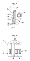
- Figs. 6 to 10 illustrate one example of a plate insert type ramp 51.
- the ramp 51 has a metal reinforcement plate 62 buried inside a resin ramp body 52 by insert molding. In these figures, dots are added to the reinforcement plate 62 so as to easily identify the reinforcement plate 62 in the ramp body 51.
- the resin ramp body 52 integrally has a function part 53 for functioning as the ramp and an attaching part 59 for attaching the ramp to a providing position.
- the function part 53 is formed in an approximately rectangular plate shape, and the reinforcement plate 62 is buried in the plate thickness of the function part 53.
- One of four sides of the function part 53 has a necessary number of recessed disk insertion parts 54 for rotatably inserting peripheral edge parts of disks 65 (refer to Fig.
- the reinforcement plate 62 is formed in an approximately rectangular shape so as to be somewhat smaller than the function part 53, and has transparent holes 63, cutout parts 64 and the like. Further, as an illustrated cross section in Fig. 9 , peripheral edge parts 62a, 62b, 62c and 62d at all four sides of the reinforcement plate 62 are buried in the resin.
- the material of the ramp body 52 has been substituted from LCP to POM (polyacetal) excellent in friction and abrasion properties in recent years.
- the reinforcement plate 62 is inserted into the POM having a similar structure in the case of LCP, when the ramp is subjected to an endurance test at rapid temperature changes, e.g., from -40 degree C to 80 degree C, it is found out that breakage occurs at a contacting part of the ramp body 52 to the reinforcement plate 62 (the breakage does not occur in the case of the LCP).
- the breakage occurs along the edge of the reinforcement plate 62 at portions having thin wall parts in the resin near the edge of the reinforcement plate 62.
- the breakage seems to occur by the following reason. Since the POM has not only less mechanical strength and heat resistance property but also larger size variation by temperature than those of the LCP (heat shrinkage occurs in the thick allow directions in Fig. 9 ), the thin wall parts (B parts in Fig. 9 ) of the ramp body 52 near the peripheral edge parts 62a, 62b, 62c and 62d of the reinforcement plate 62 cannot endure the stress induced by shrinkage difference with the reinforcement plate 62 having less size variation. Thus, the breakage occurs.
- Patent Document 1 Japanese Patent Application Laid Open No. 11-339411
- Patent Document 2 Japanese Patent Application Laid Open No. 2001-23325
- the present invention is to solve the above-described problems, and an objective of the present invention is to provide a breakage prevention structure of a ramp capable of effectively suppressing the occurrence of breakage in a resin near plate peripheral edge parts by heat shrinkage without increasing the thickness of the resin near the plate peripheral edge parts or without reducing the thickness of the plate.
- a breakage prevention structure has the feature that, in a plate insert type ramp having a resin ramp body and a metal reinforcement plate buried in the ramp body by insert molding, a part or all of the peripheral edge parts of the reinforcement plate are exposed from the surface of the ramp body beforehand to prevent the resin near the peripheral edge parts of the reinforcement plate from being broken due to heat shrinkage.
- a breakage prevention structure according to claim 2 of the present invention has the feature that, in the above-described breakage prevention structure of a ramp according to claim 1, the reinforcement plate is exposed from the front surface at clearance portions between a plurality of disk insertion parts formed at one of four sides of the ramp body and/or the peripheral edge parts of the ramp body at its other three sides.
- the reason why breakage easily occurs in the conventional resin ramp body 52 is that a part of the resin is adhered to the outer peripheral side of the peripheral edge parts 62a, 62b, 62c and 62d of the reinforcement plate 62 buried in the ramp body 52 so as to be easily stressed by heat shrinkage.
- the peripheral edge parts of the reinforcement plate are exposed from the surface of the ramp body beforehand, so that there is no resin to be easily stressed at the outer peripheral side of the reinforcement plate. Therefore, according to the present invention, the occurrence of large stress in the resin can be prevented, and thus the occurrence of breakage in the resin ramp body can be effectively prevented.
- the breakage easily occurs at the clearance portions, being thin wall parts in the ramp body between a plurality of disk insertion parts formed at one of four sides of the ramp body, and the peripheral edge parts of the ramp body at its other three sides.
- the reinforcement plate is preferably exposed from the clearance portions between a plurality of disk insertion parts formed at one of four sides of the ramp body and/or the peripheral edge parts of the ramp body at its other three sides.
- the present invention has the following effects.
- the peripheral edge part of the reinforcement part which is an insert member, is exposed from the surface of the resin beforehand, so that there is no resin to be easily stressed by heat shrinkage at the outer peripheral side of the reinforcement plate.
- the occurrence of breakage in a resin which occurs due to heat shrinkage can be prevented. Therefore, since the breakage in the resin can be prevented by this new technique, the occurrence of breakage in a resin near plate peripheral edge part due to heat shrinkage can be effectively suppressed so as to attain the desired objective without increasing the wall thickness of the resin near the plate peripheral edge part or without reducing the thickness of the plate.
- moldability of the product can be increased.
- the flowability of the resin since the flowability of the resin is not good at thin wall parts, poor filling of resin easily occurs.
- burrs are easily generated at a divided part of a mold or matching surfaces of both molds.
- a product does not have the thin wall part since the peripheral edge part of the plate is exposed from the front surface, so that occurrence of the poor filling can be suppressed even if not increasing the injection pressure so as to improve filling efficiency. Therefore, it can be effectively suppressed the occurrence of the burrs, and thus moldability of the product can be improved.
- a consumption volume of the material can be reduced at a low level.
- the present invention does not have the resin material covering the plate peripheral edge part, so that the consumption volume of the resin material can be lowered.
- the reinforcement plate is exposed from the front surface at the clearance portions between a plurality of disk insertion parts formed at one of four sides of the ramp body and/or the peripheral edge parts of the ramp body at its other three sides.
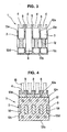
- Fig. 1 is a front view of a plate insert type ramp 1 according an example of the present invention.
- Fig. 2 is a side view of the ramp 1
- Fig. 3 is a rear view of the ramp 1
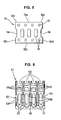
- Fig. 4 is a cross sectional view of the ramp 1 taken along the C-C line in Fig. 2 .
- Fig. 5 is a single part view of a reinforcement plate 12 in the ramp 1.
- the ramp 1 has a ramp body 2 made of a resin material such as POM or the like, and a metal reinforcement plate 12 buried in the ramp body 2 by insert molding.
- dots are added to the reinforcement plate 12 so as to easily identify the reinforcement plate 12 in the ramp body 2.
- the resin ramp body 2 integrally has a function part 3 for functioning as the ramp and an attaching part 9 for attaching the ramp to a position where the ramp is to be provided.
- the function part 3 is formed in an approximately rectangular plate shape, and the reinforcement plate 12 is buried in the plate thickness of the function part 3.
- One of four sides of the function part 3 has the necessary number of recessed disk insertion parts 4 for rotatably inserting peripheral edge parts (refer to Fig. 4 ) of disks 15 in a non-contacting state.
- a surface opposite to the side of the attaching part 9 has respective necessary numbers of lift tab sliding surfaces 5 for slidably guiding and standing by a lift tab (not illustrated) at a top end of a head, lift tab restricting parts 6 working as a limiter to the lift tab, and flexure restricting parts 7 working as a limiter to a flexure (not illustrated).
- the attaching part 9 is also formed in a plate shape and arranged so as to vertically cross to the plate of the function part 3.
- the attaching part 9 has a necessary number of hole parts 10 and 11 (two hole parts in the figure) in the plane thereof.
- the hole parts 10 and 11 are screw holes, through holes or the like and used for attaching the ramp 1.
- the reinforcement plate 12 is formed in an approximately rectangular shape which is somewhat smaller than the function part 3, and has transparent holes 13 and cutouts 14 as illustrated in a single part view of Fig. 5 . Further, as illustrated in a cross sectional view in Fig. 4 , peripheral edge parts 12a, 12b, 12c and 12d are exposed from a front surface as follows.
- the upper side part 12a in Fig. 4 which is positioned at the disk insertion part 4 side, the upper side part 12a is exposed from the front surface of the ramp body at clearance portions 8 between a plurality of disk insertion parts 4 and at both end parts 12e of the upper side part 12a.
- the whole lower side part 12b is exposed from the front surface of the ramp body.
- the parts except the cutouts 14 formed at the side parts 12c and 12d are exposed from the front surface of the ramp body.
- the peripheral edge parts 12b, 12c and 12d of the reinforcement plate 12 in this embodiment are exposed to the front surface.
- the peripheral edge parts of the ramp body 2 are formed with the peripheral edge parts 12b, 12c and 12d of the reinforcement plate 12.
- the resin adhered at the outer peripheral sides of the peripheral edge parts 12a, 12b, 12c and 12d of the reinforcement plate 12 are limited to the minimum required for functions, so that almost all parts of the peripheral edge parts 12a, 12b, 12c and 12d are exposed from the front surface of the ramp body.
- the moldability of the product of the ramp 1 can be improved, and the consumption volume of a resin material can be reduced.
- the material of the resin ramp body 2 is not restricted to the POM, and the other kinds of resin materials can be used.
- the POM has been mainly used as the material of a resin ramp in the recent technique as described above, but the problem of breakage by heat shrinkage is not limited only in the case of POM.
Landscapes
- Injection Moulding Of Plastics Or The Like (AREA)
- Non-Portable Lighting Devices Or Systems Thereof (AREA)
- Vessels And Coating Films For Discharge Lamps (AREA)
- Supporting Of Heads In Record-Carrier Devices (AREA)
Abstract
Description
- The present invention relates to a ramp mechanism used for a data storage apparatus such as an HDD (a hard disk drive) or the like, and more particularly, a plate insert type ramp having a metal reinforcement plate buried in a resin ramp body by insert molding.
- In a hard disk of a load/unload system, a ramp is provided near the disk as a refuge space of a head. As the material of a ramp, a resin material has been used for preventing metal contamination caused due to friction with a tab. However, since the size variation of the resin material by heat is large, there are problems at a high temperature that the disk is interfered with a top end part of the ramp, and tabs in a slope part are interfered each other. More particularly, when the number of disk is increased, the size of a ramp is also increased, so that the size of the resin material is more remarkably varied. As for the material of the ramp, LCP (a liquid crystal polymer) having an excellent heat resistance property, low out gas property and size stability has been used. However, the material of LCP is not enough to prevent varying of the size thereof. Thus, in order to solve this problem, a metal reinforcement plate is inserted into a ramp of an apparatus having much number of disks (refer to Patent Documents 1 and 2).
-
Figs. 6 to 10 illustrate one example of a plateinsert type ramp 51. Theramp 51 has ametal reinforcement plate 62 buried inside aresin ramp body 52 by insert molding. In these figures, dots are added to thereinforcement plate 62 so as to easily identify thereinforcement plate 62 in theramp body 51. Theresin ramp body 52 integrally has afunction part 53 for functioning as the ramp and an attachingpart 59 for attaching the ramp to a providing position. Thefunction part 53 is formed in an approximately rectangular plate shape, and thereinforcement plate 62 is buried in the plate thickness of thefunction part 53. One of four sides of thefunction part 53 has a necessary number of recesseddisk insertion parts 54 for rotatably inserting peripheral edge parts of disks 65 (refer toFig. 9 ) in a non-contacting state. Further, a surface opposite to the side of the attachingpart 59 has respective necessary numbers of lifttab sliding surfaces 55, lifttab restricting parts 56,flexure restricting parts 57 and the like. As an illustrated single part inFig. 10 , thereinforcement plate 62 is formed in an approximately rectangular shape so as to be somewhat smaller than thefunction part 53, and hastransparent holes 63,cutout parts 64 and the like. Further, as an illustrated cross section inFig. 9 ,peripheral edge parts reinforcement plate 62 are buried in the resin. - On the other hand, the material of the
ramp body 52 has been substituted from LCP to POM (polyacetal) excellent in friction and abrasion properties in recent years. However, in the case that thereinforcement plate 62 is inserted into the POM having a similar structure in the case of LCP, when the ramp is subjected to an endurance test at rapid temperature changes, e.g., from -40 degree C to 80 degree C, it is found out that breakage occurs at a contacting part of theramp body 52 to the reinforcement plate 62 (the breakage does not occur in the case of the LCP). - The breakage occurs along the edge of the
reinforcement plate 62 at portions having thin wall parts in the resin near the edge of thereinforcement plate 62. The breakage seems to occur by the following reason. Since the POM has not only less mechanical strength and heat resistance property but also larger size variation by temperature than those of the LCP (heat shrinkage occurs in the thick allow directions inFig. 9 ), the thin wall parts (B parts inFig. 9 ) of theramp body 52 near theperipheral edge parts reinforcement plate 62 cannot endure the stress induced by shrinkage difference with thereinforcement plate 62 having less size variation. Thus, the breakage occurs. - In order to prevent the occurrence of breakage, it is considered that the wall thickness of the resin near the plate
peripheral edges - Even if when the thickness of the resin near the plate
peripheral edges - Further, when the thickness of
reinforcement plate 62 is reduced to prevent the breakage, an insert work is hard due to the thin thickness, and thereinforcement plate 62 may be deformed by an injection pressure. Further, the thickness of thereinforcement plate 62 is about 0.5 mm in the conventional structure, so this is an already thin enough. Thus, if the thickness is reduced more, there may be a problem of a functional side, that is, for size fixing.
Patent Document 1: Japanese Patent Application Laid Open No.11-339411
Patent Document 2: Japanese Patent Application Laid Open No.2001-23325 - The present invention is to solve the above-described problems, and an objective of the present invention is to provide a breakage prevention structure of a ramp capable of effectively suppressing the occurrence of breakage in a resin near plate peripheral edge parts by heat shrinkage without increasing the thickness of the resin near the plate peripheral edge parts or without reducing the thickness of the plate.
- In order to effectively solve the above-described technical problems, a breakage prevention structure according to claim 1 of the present invention has the feature that, in a plate insert type ramp having a resin ramp body and a metal reinforcement plate buried in the ramp body by insert molding, a part or all of the peripheral edge parts of the reinforcement plate are exposed from the surface of the ramp body beforehand to prevent the resin near the peripheral edge parts of the reinforcement plate from being broken due to heat shrinkage.
- Further, a breakage prevention structure according to
claim 2 of the present invention has the feature that, in the above-described breakage prevention structure of a ramp according to claim 1, the reinforcement plate is exposed from the front surface at clearance portions between a plurality of disk insertion parts formed at one of four sides of the ramp body and/or the peripheral edge parts of the ramp body at its other three sides. - The reason why breakage easily occurs in the conventional
resin ramp body 52 is that a part of the resin is adhered to the outer peripheral side of theperipheral edge parts reinforcement plate 62 buried in theramp body 52 so as to be easily stressed by heat shrinkage. On the other hand, according to the present invention, the peripheral edge parts of the reinforcement plate are exposed from the surface of the ramp body beforehand, so that there is no resin to be easily stressed at the outer peripheral side of the reinforcement plate. Therefore, according to the present invention, the occurrence of large stress in the resin can be prevented, and thus the occurrence of breakage in the resin ramp body can be effectively prevented. - In addition, as described in the undermentioned examples, the breakage easily occurs at the clearance portions, being thin wall parts in the ramp body between a plurality of disk insertion parts formed at one of four sides of the ramp body, and the peripheral edge parts of the ramp body at its other three sides. Thus, to cope with such problems, the reinforcement plate is preferably exposed from the clearance portions between a plurality of disk insertion parts formed at one of four sides of the ramp body and/or the peripheral edge parts of the ramp body at its other three sides.
- The present invention has the following effects.
- In the breakage prevention structure of a ramp according to claim 1 of the present invention having the above-described structure, the peripheral edge part of the reinforcement part, which is an insert member, is exposed from the surface of the resin beforehand, so that there is no resin to be easily stressed by heat shrinkage at the outer peripheral side of the reinforcement plate. As a result of this, the occurrence of breakage in a resin which occurs due to heat shrinkage can be prevented. Therefore, since the breakage in the resin can be prevented by this new technique, the occurrence of breakage in a resin near plate peripheral edge part due to heat shrinkage can be effectively suppressed so as to attain the desired objective without increasing the wall thickness of the resin near the plate peripheral edge part or without reducing the thickness of the plate.
- Further, according to the present invention, moldability of the product can be increased. In particular, at the time of molding the resin, since the flowability of the resin is not good at thin wall parts, poor filling of resin easily occurs. When injection pressure is increased in order to prevent this poor filling, burrs are easily generated at a divided part of a mold or matching surfaces of both molds. On the other hand, according to the present invention, a product does not have the thin wall part since the peripheral edge part of the plate is exposed from the front surface, so that occurrence of the poor filling can be suppressed even if not increasing the injection pressure so as to improve filling efficiency. Therefore, it can be effectively suppressed the occurrence of the burrs, and thus moldability of the product can be improved.
- Further, according to the present invention, a consumption volume of the material can be reduced at a low level. In particular, the present invention does not have the resin material covering the plate peripheral edge part, so that the consumption volume of the resin material can be lowered.
- Further, in the breakage prevention structure of a ramp according to
claim 2 of the present invention, the reinforcement plate is exposed from the front surface at the clearance portions between a plurality of disk insertion parts formed at one of four sides of the ramp body and/or the peripheral edge parts of the ramp body at its other three sides. Thus, the occurrence of breakage by heat shrinkage at the clearance portions and/or the peripheral edge parts can be effectively prevented. -
- [
Fig. 1 ] A front view of a ramp according to an example of the present invention - [
Fig. 2 ] A side view of the ramp ofFig. 1 - [
Fig. 3 ] A rear view of the ramp ofFig. 1 - [
Fig. 4 ] A cross sectional view of the ramp ofFig. 1 taken along the line C-C inFig. 2 - [
Fig. 5 ] A single part view of a plate in the ramp ofFig. 1 - [
Fig. 6 ] A front view of a ramp according to a conventional example - [
Fig. 7 ] A side view of the ramp ofFig. 6 - [
Fig. 8 ] A rear view of the ramp ofFig. 6 - [
Fig. 9 ] A cross sectional view of the ramp ofFig. 6 taken along the line A-A inFig. 7 - [
Fig. 10 ] A single part view of a plate in the ramp ofFig. 6 -
- 1: Ramp
- 2: Ramp body
- 3: Function part
- 4: Disk insertion part
- 5: Lift tab sliding surface
- 6: Lift tab restricting part
- 7: Flexure restricting part
- 8: Clearance portion
- 9: Attaching part
- 10, 11: Hole parts
- 12: Reinforcement plate
- 12a: Upper side part (a peripheral edge part)
- 12b: Lower side part (a peripheral edge part)
- 12c, 12d: side parts (peripheral edge parts)
- 12e: Both end parts
- 13: Transparent hole
- 14: Cutout
- 15: Disk
- Then, an embodiment of the present invention will be concretely described with drawings.
-
Fig. 1 is a front view of a plate insert type ramp 1 according an example of the present invention.Fig. 2 is a side view of the ramp 1,Fig. 3 is a rear view of the ramp 1, andFig. 4 is a cross sectional view of the ramp 1 taken along the C-C line inFig. 2 . Further,Fig. 5 is a single part view of areinforcement plate 12 in the ramp 1. - As illustrated in
Figs . 1 to 4 , the ramp 1 according to the embodiment has aramp body 2 made of a resin material such as POM or the like, and ametal reinforcement plate 12 buried in theramp body 2 by insert molding. In those figures, dots are added to thereinforcement plate 12 so as to easily identify thereinforcement plate 12 in theramp body 2. - The
resin ramp body 2 integrally has afunction part 3 for functioning as the ramp and an attaching part 9 for attaching the ramp to a position where the ramp is to be provided. Thefunction part 3 is formed in an approximately rectangular plate shape, and thereinforcement plate 12 is buried in the plate thickness of thefunction part 3. - One of four sides of the
function part 3 has the necessary number of recesseddisk insertion parts 4 for rotatably inserting peripheral edge parts (refer toFig. 4 ) ofdisks 15 in a non-contacting state. Further, a surface opposite to the side of the attaching part 9 has respective necessary numbers of lifttab sliding surfaces 5 for slidably guiding and standing by a lift tab (not illustrated) at a top end of a head, lifttab restricting parts 6 working as a limiter to the lift tab, andflexure restricting parts 7 working as a limiter to a flexure (not illustrated). - The attaching part 9 is also formed in a plate shape and arranged so as to vertically cross to the plate of the
function part 3. The attaching part 9 has a necessary number ofhole parts 10 and 11 (two hole parts in the figure) in the plane thereof. Thehole parts - On the other hand, the
reinforcement plate 12 is formed in an approximately rectangular shape which is somewhat smaller than thefunction part 3, and hastransparent holes 13 andcutouts 14 as illustrated in a single part view ofFig. 5 . Further, as illustrated in a cross sectional view inFig. 4 ,peripheral edge parts - As for the
upper side part 12a inFig. 4 , which is positioned at thedisk insertion part 4 side, theupper side part 12a is exposed from the front surface of the ramp body atclearance portions 8 between a plurality ofdisk insertion parts 4 and at bothend parts 12e of theupper side part 12a. - Further, as for the
lower side part 12b being opposite side of thedisk insertion parts 4 inFig. 4 , the wholelower side part 12b is exposed from the front surface of the ramp body. - Further, as for the
side parts Fig. 4 , the parts except thecutouts 14 formed at theside parts - Therefore, as for the
lower side part 12b andside parts ramp body 2 are conventionally formed by a resin, theperipheral edge parts reinforcement plate 12 in this embodiment are exposed to the front surface. Thus, the peripheral edge parts of theramp body 2 are formed with theperipheral edge parts reinforcement plate 12. - As a result of this, the resin adhered at the outer peripheral sides of the
peripheral edge parts reinforcement plate 12 are limited to the minimum required for functions, so that almost all parts of theperipheral edge parts peripheral edge parts peripheral edge parts resin ramp body 2 by heat shrinkage can be effectively prevented. - Further, according to the ramp 1 having the above-described structure, the moldability of the product of the ramp 1 can be improved, and the consumption volume of a resin material can be reduced.
- In addition, in the present invention, the material of the
resin ramp body 2 is not restricted to the POM, and the other kinds of resin materials can be used. The POM has been mainly used as the material of a resin ramp in the recent technique as described above, but the problem of breakage by heat shrinkage is not limited only in the case of POM.
Claims (2)
- A breakage prevention structure of a plate insert type ramp (1) having a resin ramp body (2) and a metal reinforcement plate (12) buried in the ramp body (2) by insert molding, wherein a part or all of the peripheral edge parts (12a), (12b), (12c), and (12d) of the reinforcement plate (12) are exposed from the front surface of the ramp body (2) beforehand to prevent the resin near the peripheral edge parts (12a), (12b), (12c), and (12d) of the reinforcement plate (12) from being broken due to heat shrinkage.
- The breakage prevention structure of a ramp as claimed in claim 1, wherein the reinforcement plate (12) is exposed from the front surface of clearance portions (8) between a plurality of disk insertion parts (4) formed at one of four sides of the ramp body (2) and/or the peripheral edge parts of the ramp body (2) at its other three sides.
Applications Claiming Priority (2)
| Application Number | Priority Date | Filing Date | Title |
|---|---|---|---|
| JP2005261934A JP2007073167A (en) | 2005-09-09 | 2005-09-09 | Structure for preventing break of lamp |
| PCT/JP2006/307804 WO2007029372A1 (en) | 2005-09-09 | 2006-04-13 | Breakage prevention structure of lamp |
Publications (2)
| Publication Number | Publication Date |
|---|---|
| EP1923885A1 true EP1923885A1 (en) | 2008-05-21 |
| EP1923885A4 EP1923885A4 (en) | 2008-09-03 |
Family
ID=37835506
Family Applications (1)
| Application Number | Title | Priority Date | Filing Date |
|---|---|---|---|
| EP06731740A Withdrawn EP1923885A4 (en) | 2005-09-09 | 2006-04-13 | Breakage prevention structure of lamp |
Country Status (6)
| Country | Link |
|---|---|
| US (1) | US20100226231A1 (en) |
| EP (1) | EP1923885A4 (en) |
| JP (1) | JP2007073167A (en) |
| KR (1) | KR20080047598A (en) |
| CN (1) | CN101258550A (en) |
| WO (1) | WO2007029372A1 (en) |
Families Citing this family (1)
| Publication number | Priority date | Publication date | Assignee | Title |
|---|---|---|---|---|
| US10943614B1 (en) * | 2020-02-18 | 2021-03-09 | Western Digital Technologies, Inc. | Load/unload ramp mechanism for reduced cracking |
Family Cites Families (7)
| Publication number | Priority date | Publication date | Assignee | Title |
|---|---|---|---|---|
| JP3751078B2 (en) * | 1996-03-29 | 2006-03-01 | キョーラク株式会社 | Hollow double wall molded article and method for producing the same |
| JPH10156864A (en) * | 1996-11-28 | 1998-06-16 | Nippon Zeon Co Ltd | Elongated member insert molded body and method of manufacturing the same |
| US6160686A (en) | 1998-05-14 | 2000-12-12 | International Business Machines Corporation | Composite ramp structure for data storage devices |
| US6487050B1 (en) * | 1999-02-22 | 2002-11-26 | Seagate Technology Llc | Disc drive with wear-resistant ramp coating of carbon nitride or metal nitride |
| JP2001023325A (en) * | 1999-06-29 | 2001-01-26 | Internatl Business Mach Corp <Ibm> | Composite ramp structure of data storage device |
| JP2002240079A (en) * | 2001-02-21 | 2002-08-28 | Nippon Zeon Co Ltd | Molded body |
| JP2003022636A (en) * | 2001-07-04 | 2003-01-24 | Taiheiyo Cement Corp | Hard disk device |
-
2005
- 2005-09-09 JP JP2005261934A patent/JP2007073167A/en active Pending
-
2006
- 2006-04-13 US US11/991,738 patent/US20100226231A1/en not_active Abandoned
- 2006-04-13 EP EP06731740A patent/EP1923885A4/en not_active Withdrawn
- 2006-04-13 WO PCT/JP2006/307804 patent/WO2007029372A1/en not_active Ceased
- 2006-04-13 KR KR1020087008443A patent/KR20080047598A/en not_active Ceased
- 2006-04-13 CN CNA2006800323533A patent/CN101258550A/en active Pending
Also Published As
| Publication number | Publication date |
|---|---|
| US20100226231A1 (en) | 2010-09-09 |
| WO2007029372A1 (en) | 2007-03-15 |
| CN101258550A (en) | 2008-09-03 |
| EP1923885A4 (en) | 2008-09-03 |
| KR20080047598A (en) | 2008-05-29 |
| JP2007073167A (en) | 2007-03-22 |
Similar Documents
| Publication | Publication Date | Title |
|---|---|---|
| US9147436B2 (en) | Slim form factor disk drive comprising disk drive enclosure having an insular raised region | |
| US12309960B2 (en) | Electronic device and bracket thereof | |
| US20080030934A1 (en) | Electronic device and keyboard thereof | |
| US7782599B2 (en) | Computer device with stiffened display member | |
| US8469466B2 (en) | Computer enclosure | |
| US20160293223A1 (en) | Memory drive storage tray and memory drive carrier for use therewith | |
| US5383553A (en) | Case for receiving at least one data storage disk | |
| US9418707B2 (en) | Accommodating case for portable recording medium | |
| WO2006096367A3 (en) | Optical disc having a reduced planar thickness | |
| US20100226231A1 (en) | Breakage Prevention Structure of Ramp | |
| CN102612293B (en) | Electronic device, positioning piece and electronic component fixing module | |
| CN1100713C (en) | Cases for accommonating disc cartridges | |
| US20090194490A1 (en) | Plate and sliding connection apparatus | |
| JP2007073168A (en) | Structure for preventing break of lamp | |
| CN1153213C (en) | Magnetic tape cassette | |
| CN100431026C (en) | CD device | |
| US6097594A (en) | Recessed bezel for tape drive | |
| CN103176543A (en) | Fixing device for data storage device | |
| CN2864792Y (en) | Hard disk fixing device | |
| US11476534B2 (en) | Electronic device including battery and battery compartment | |
| CN1910697B (en) | CD device | |
| US11940854B2 (en) | Replacement device and electronic device | |
| US20070067782A1 (en) | Slim-type recording and reproducing apparatus having positioning structure for positioning a tray therein | |
| US8104052B2 (en) | Slot-in type disk apparatus including a base body and lid forming a chassis sheath provided with a bezel | |
| EP3309786B1 (en) | Disc drive |
Legal Events
| Date | Code | Title | Description |
|---|---|---|---|
| PUAI | Public reference made under article 153(3) epc to a published international application that has entered the european phase |
Free format text: ORIGINAL CODE: 0009012 |
|
| 17P | Request for examination filed |
Effective date: 20080312 |
|
| AK | Designated contracting states |
Kind code of ref document: A1 Designated state(s): DE FR GB |
|
| A4 | Supplementary search report drawn up and despatched |
Effective date: 20080801 |
|
| RIC1 | Information provided on ipc code assigned before grant |
Ipc: G11B 5/54 20060101ALI20080728BHEP Ipc: G11B 21/12 20060101AFI20070524BHEP Ipc: G11B 21/22 20060101ALI20080728BHEP |
|
| RBV | Designated contracting states (corrected) |
Designated state(s): DE FR GB |
|
| 17Q | First examination report despatched |
Effective date: 20090330 |
|
| STAA | Information on the status of an ep patent application or granted ep patent |
Free format text: STATUS: THE APPLICATION IS DEEMED TO BE WITHDRAWN |
|
| 18D | Application deemed to be withdrawn |
Effective date: 20090811 |