EP1923459A1 - A bioreactor - Google Patents
A bioreactor Download PDFInfo
- Publication number
- EP1923459A1 EP1923459A1 EP07254451A EP07254451A EP1923459A1 EP 1923459 A1 EP1923459 A1 EP 1923459A1 EP 07254451 A EP07254451 A EP 07254451A EP 07254451 A EP07254451 A EP 07254451A EP 1923459 A1 EP1923459 A1 EP 1923459A1
- Authority
- EP
- European Patent Office
- Prior art keywords
- bioreactor
- length
- volumes
- volume
- gas
- Prior art date
- Legal status (The legal status is an assumption and is not a legal conclusion. Google has not performed a legal analysis and makes no representation as to the accuracy of the status listed.)
- Withdrawn
Links
- 239000000463 material Substances 0.000 claims abstract description 15
- 239000000376 reactant Substances 0.000 claims description 23
- 239000007789 gas Substances 0.000 description 48
- 210000004027 cell Anatomy 0.000 description 24
- 229920003023 plastic Polymers 0.000 description 16
- 239000004033 plastic Substances 0.000 description 16
- 239000007788 liquid Substances 0.000 description 15
- 230000033001 locomotion Effects 0.000 description 13
- 235000015097 nutrients Nutrition 0.000 description 12
- 238000004113 cell culture Methods 0.000 description 9
- 238000006243 chemical reaction Methods 0.000 description 7
- -1 polyethylene Polymers 0.000 description 7
- 239000010410 layer Substances 0.000 description 5
- 238000000034 method Methods 0.000 description 5
- 239000000126 substance Substances 0.000 description 5
- CURLTUGMZLYLDI-UHFFFAOYSA-N Carbon dioxide Chemical compound O=C=O CURLTUGMZLYLDI-UHFFFAOYSA-N 0.000 description 4
- 239000012530 fluid Substances 0.000 description 4
- 239000012528 membrane Substances 0.000 description 4
- 239000011148 porous material Substances 0.000 description 4
- 230000008569 process Effects 0.000 description 4
- 229920000219 Ethylene vinyl alcohol Polymers 0.000 description 3
- 239000004698 Polyethylene Substances 0.000 description 3
- 239000004743 Polypropylene Substances 0.000 description 3
- 230000000694 effects Effects 0.000 description 3
- 238000000855 fermentation Methods 0.000 description 3
- 230000004151 fermentation Effects 0.000 description 3
- 239000011521 glass Substances 0.000 description 3
- 230000012010 growth Effects 0.000 description 3
- 230000002209 hydrophobic effect Effects 0.000 description 3
- 239000000203 mixture Substances 0.000 description 3
- 229920001200 poly(ethylene-vinyl acetate) Polymers 0.000 description 3
- 229920000573 polyethylene Polymers 0.000 description 3
- 229920000098 polyolefin Polymers 0.000 description 3
- 229920001155 polypropylene Polymers 0.000 description 3
- 238000011144 upstream manufacturing Methods 0.000 description 3
- 239000002699 waste material Substances 0.000 description 3
- 239000000853 adhesive Substances 0.000 description 2
- 230000001070 adhesive effect Effects 0.000 description 2
- 239000001569 carbon dioxide Substances 0.000 description 2
- 229910002092 carbon dioxide Inorganic materials 0.000 description 2
- 238000012423 maintenance Methods 0.000 description 2
- 238000004519 manufacturing process Methods 0.000 description 2
- 230000000813 microbial effect Effects 0.000 description 2
- 229920001778 nylon Polymers 0.000 description 2
- 239000002985 plastic film Substances 0.000 description 2
- 229920006255 plastic film Polymers 0.000 description 2
- 229920002492 poly(sulfone) Polymers 0.000 description 2
- 229910001220 stainless steel Inorganic materials 0.000 description 2
- 239000010935 stainless steel Substances 0.000 description 2
- 108090000790 Enzymes Proteins 0.000 description 1
- 102000004190 Enzymes Human genes 0.000 description 1
- 239000002033 PVDF binder Substances 0.000 description 1
- 239000004695 Polyether sulfone Substances 0.000 description 1
- 229920000690 Tyvek Polymers 0.000 description 1
- 239000004775 Tyvek Substances 0.000 description 1
- 230000009471 action Effects 0.000 description 1
- 230000002411 adverse Effects 0.000 description 1
- 235000013334 alcoholic beverage Nutrition 0.000 description 1
- QVGXLLKOCUKJST-UHFFFAOYSA-N atomic oxygen Chemical compound [O] QVGXLLKOCUKJST-UHFFFAOYSA-N 0.000 description 1
- 230000010261 cell growth Effects 0.000 description 1
- 239000006285 cell suspension Substances 0.000 description 1
- 230000003833 cell viability Effects 0.000 description 1
- 239000000919 ceramic Substances 0.000 description 1
- 230000008859 change Effects 0.000 description 1
- 238000011109 contamination Methods 0.000 description 1
- 238000009826 distribution Methods 0.000 description 1
- 230000007613 environmental effect Effects 0.000 description 1
- 239000005038 ethylene vinyl acetate Substances 0.000 description 1
- 210000003527 eukaryotic cell Anatomy 0.000 description 1
- 229920002457 flexible plastic Polymers 0.000 description 1
- 239000006260 foam Substances 0.000 description 1
- 238000005187 foaming Methods 0.000 description 1
- 229920001519 homopolymer Polymers 0.000 description 1
- 230000006872 improvement Effects 0.000 description 1
- 238000000338 in vitro Methods 0.000 description 1
- 229920000092 linear low density polyethylene Polymers 0.000 description 1
- 239000004707 linear low-density polyethylene Substances 0.000 description 1
- 210000004962 mammalian cell Anatomy 0.000 description 1
- 244000005700 microbiome Species 0.000 description 1
- 229910052760 oxygen Inorganic materials 0.000 description 1
- 239000001301 oxygen Substances 0.000 description 1
- 230000000737 periodic effect Effects 0.000 description 1
- 239000004417 polycarbonate Substances 0.000 description 1
- 229920000515 polycarbonate Polymers 0.000 description 1
- 229920006393 polyether sulfone Polymers 0.000 description 1
- 229920001343 polytetrafluoroethylene Polymers 0.000 description 1
- 239000004810 polytetrafluoroethylene Substances 0.000 description 1
- 229920002981 polyvinylidene fluoride Polymers 0.000 description 1
- 239000002243 precursor Substances 0.000 description 1
- 238000011045 prefiltration Methods 0.000 description 1
- 108090000623 proteins and genes Proteins 0.000 description 1
- 102000004169 proteins and genes Human genes 0.000 description 1
- 238000011084 recovery Methods 0.000 description 1
- 230000010076 replication Effects 0.000 description 1
- 229920005989 resin Polymers 0.000 description 1
- 239000011347 resin Substances 0.000 description 1
- 239000011435 rock Substances 0.000 description 1
- 238000007789 sealing Methods 0.000 description 1
- 239000002356 single layer Substances 0.000 description 1
- 239000007787 solid Substances 0.000 description 1
- 239000007858 starting material Substances 0.000 description 1
- 230000003068 static effect Effects 0.000 description 1
- 238000003860 storage Methods 0.000 description 1
- 150000003440 styrenes Chemical class 0.000 description 1
- 230000003319 supportive effect Effects 0.000 description 1
- 229920001169 thermoplastic Polymers 0.000 description 1
- 239000004416 thermosoftening plastic Substances 0.000 description 1
- 239000003053 toxin Substances 0.000 description 1
- 231100000765 toxin Toxicity 0.000 description 1
- 108700012359 toxins Proteins 0.000 description 1
- 229960005486 vaccine Drugs 0.000 description 1
- 238000011179 visual inspection Methods 0.000 description 1
- 239000002912 waste gas Substances 0.000 description 1
- XLYOFNOQVPJJNP-UHFFFAOYSA-N water Substances O XLYOFNOQVPJJNP-UHFFFAOYSA-N 0.000 description 1
- 239000002759 woven fabric Substances 0.000 description 1
Images



Classifications
-
- C—CHEMISTRY; METALLURGY
- C12—BIOCHEMISTRY; BEER; SPIRITS; WINE; VINEGAR; MICROBIOLOGY; ENZYMOLOGY; MUTATION OR GENETIC ENGINEERING
- C12M—APPARATUS FOR ENZYMOLOGY OR MICROBIOLOGY; APPARATUS FOR CULTURING MICROORGANISMS FOR PRODUCING BIOMASS, FOR GROWING CELLS OR FOR OBTAINING FERMENTATION OR METABOLIC PRODUCTS, i.e. BIOREACTORS OR FERMENTERS
- C12M29/00—Means for introduction, extraction or recirculation of materials, e.g. pumps
- C12M29/04—Filters; Permeable or porous membranes or plates, e.g. dialysis
-
- C—CHEMISTRY; METALLURGY
- C12—BIOCHEMISTRY; BEER; SPIRITS; WINE; VINEGAR; MICROBIOLOGY; ENZYMOLOGY; MUTATION OR GENETIC ENGINEERING
- C12M—APPARATUS FOR ENZYMOLOGY OR MICROBIOLOGY; APPARATUS FOR CULTURING MICROORGANISMS FOR PRODUCING BIOMASS, FOR GROWING CELLS OR FOR OBTAINING FERMENTATION OR METABOLIC PRODUCTS, i.e. BIOREACTORS OR FERMENTERS
- C12M23/00—Constructional details, e.g. recesses, hinges
- C12M23/26—Constructional details, e.g. recesses, hinges flexible
-
- C—CHEMISTRY; METALLURGY
- C12—BIOCHEMISTRY; BEER; SPIRITS; WINE; VINEGAR; MICROBIOLOGY; ENZYMOLOGY; MUTATION OR GENETIC ENGINEERING
- C12M—APPARATUS FOR ENZYMOLOGY OR MICROBIOLOGY; APPARATUS FOR CULTURING MICROORGANISMS FOR PRODUCING BIOMASS, FOR GROWING CELLS OR FOR OBTAINING FERMENTATION OR METABOLIC PRODUCTS, i.e. BIOREACTORS OR FERMENTERS
- C12M23/00—Constructional details, e.g. recesses, hinges
- C12M23/28—Constructional details, e.g. recesses, hinges disposable or single use
-
- C—CHEMISTRY; METALLURGY
- C12—BIOCHEMISTRY; BEER; SPIRITS; WINE; VINEGAR; MICROBIOLOGY; ENZYMOLOGY; MUTATION OR GENETIC ENGINEERING
- C12M—APPARATUS FOR ENZYMOLOGY OR MICROBIOLOGY; APPARATUS FOR CULTURING MICROORGANISMS FOR PRODUCING BIOMASS, FOR GROWING CELLS OR FOR OBTAINING FERMENTATION OR METABOLIC PRODUCTS, i.e. BIOREACTORS OR FERMENTERS
- C12M23/00—Constructional details, e.g. recesses, hinges
- C12M23/48—Holding appliances; Racks; Supports
Definitions
- This invention relates to bioreactors.
- the culture of microbial cells (fermentation) or animal and plant cells (tissue culture) are commercially-important chemical and biochemical production processes.
- Living cells are employed in these processes because living cells, using generally easily obtainable starting materials, can economically synthesize commercially-valuable chemicals including proteins such as monoclonal antibodies or enzymes; vaccines or alcoholic beverages.
- Fermentation involves the growth or maintenance of living cells in a nutrient liquid media.
- the desired microorganism or eukaryotic cell is placed in a defined medium composed of water, nutrient chemicals and dissolved gases, and allowed to grow (or multiply) to a desired culture density.
- the liquid medium must contain all the chemicals which the cells require for their life processes and also should provide the optimal environmental conditions for their continued growth and/or replication.
- a representative microbial cell culture process might utilize either a continuous stirred-tank reactor or a gas-fluidized bed reactor in which the microbe population is suspended in circulating nutrient media.
- in vitro mammalian cell culture might employ a suspended culture of cells in roller flasks or, for cells requiring surface attachment, cultures grown to confluence in tissue culture flasks containing nutrient medium above the attached cells.
- the living cells so maintained, then metabolically produce the desired product(s) from precursor chemicals introduced into the nutrient mixture.
- the desired product(s) are either purified from the liquid medium or are extracted from the cells themselves.
- One system for a bioreactor has been to use a large table, equipped with motors or hydraulics onto which a bioreactor bag is placed.
- the motors/hydraulics rock the bag providing constant movement of the cells.
- the bag has a gas and nutrient supply tube and a waste gas and waste product tube which allow for the supply of nutrients and gases such as air for aerobic organisms and the removal of waste such as respired gases, carbon dioxide and the like.
- the tubes are arranged to work with the motion of the bag to allow for a uniform movement of the gases and fluids/solids. See U.S. Pat. No. 6,190,913 .
- Such a system requires the use of capital-intensive equipment, with components that are susceptible to wear.
- the size of the bag that can be used with the table is limited by the size of table and the lifting capability of its motors/hydraulics.
- An alternative system uses a long flexible tube-like bag that has both ends attached to movable arms such that the bag after filling is suspended downwardly from the movable arm in the shape of a U. The arms are then alternately moved upward or downward relative to the other so as to cause a rocking motion and fluid movement within the bag. If desired, the midsection may contain a restriction to cause a more intimate mixing action.
- This system requires the use of a specifically shaped bag and hydraulic or other lifting equipment to cause the movement of the liquid. Additionally, due to weight considerations, the bag size and volume is restricted by the lifting capacity of the equipment and the strength of the bag.
- An improvement has been shown through the use of one or more bags that are capable of being selectively pressurized and deflated in conjunction with a disposable bio bag such as a fermenter, mixing bag, storage bag and the like.
- the pressure bag(s) may surround a selected outer portion of the bag or may be contained within an inner portion of such a bag.
- a static (non-moving) bag that contains a sparger or other device for introducing a gas into the bag.
- the gas causes the movement of the fluid in the bag as well to cause the mixing and transfer of gases, nutrients and waste products.
- U.S. Pat. No. 5,565,015 uses a flat, inflatable porous tube that is sealed into a plastic container.
- the tube inflates under gas pressure and allows gas to flow into the bag. When the gas is not applied, the tube collapses and substantially closes off the pores of the flat tube to prevent leakage from the bag.
- U.S. Pat. No. 6,432,698 also inserts and seals a tube to a gas diffuser within the bag. It appears that a constant positive gas pressure must be maintained in order to prevent any liquid within the bag from entering the diffuser and then the gas line and eventually the air pump as no valve or other means for preventing backflow is shown.
- Both of the structures disclosed by these two patents have the potential for leakage of the liquid in the container which can potentially contaminate the contents of the bag of the upstream components of the system such as the gas supply system. Additionally, both introduce a separate component for the gas distribution.
- the present invention provides a self-standing disposable bioreactor which is linearly scaleable to any desired volume. More particularly, this invention provides a bioreactor wherein its length dimension can be increased while maintaining a constant aspect ratio (width/ height) in the volume of the reactor wherein bioreaction is effected. In addition, due to the lack of fixtures required, the self standing bioreactor is flexible and can conform to different space restrictions.
- the present invention provides a disposable, self standing bioreactor which is linearly scaleable.
- linearly scaleable as used herein with reference to a bioreactor having a height, width and length is meant expandable in the length direction of the bioreactor while maintaining the aspect ratio (width/height) of the bioreactor constant.
- the mixing conditions within the bioreactor can be maintained essentially constant while increasing the effective volume of the bioreactor.
- the bioreactor is rendered self standing such as by a support rod which extends through at least one loop.
- at least a portion of the bioreactor is either formed of a more rigid plastic or has a more rigid plastic attached to an outer portion of the bioreactor to provide additional support.
- the bioreactor includes means for introducing gas and for removing gas.
- the bioreactor also includes means for adding reactants and for removing desired product(s).
- the bioreactor is formed of a flexible material such as a polymeric composition which can be folded upon itself, wound on itself or clamped on itself to form a seal.
- the flexible material does not contaminate the reactants or the products. Since the bioreactor is flexible, it can be bent on itself to fit into a wide variety of spaces.
- the bioreactor is formed such that it has no horizontal or substantially horizontal surface upon which the cells can deposit This may be accomplished by either using a horizontal surface which has a gas supply that forms bubbles through it so that cells are pushed away from that surface or by using an angled inner wall of the reactor or both.
- the angled inner wall is substantially vertical.
- the bioreactor is also shaped to affect movement of reactant liquid upwardly along an inner surface of an outer wall of the bioreactor and then downwardly within the reactant volume remote for the inner surface of the outer wall of the bioreactor.
- the bioreactor includes a first inner surface of an outer wall which forms a closed volume with a second inner surface of an inner wall of the bioreactor.
- the first and second inner surfaces have at least a portion thereof which converge toward each other or diverge away from each other so that movement of reactant liquid within the bioreactor is in an essentially spiral direction under the influence of gases introduced into the bioreactor.
- a disposable, expandable bioreactor having a constant aspect ratio and constant cross section which includes its height and width wherein the bioreactor's effective volume is increased by increasing its length.
- the bioreactor initially has a relatively small effective volume into which a cell culture, nutrients and one or more gases are introduced to effect a bioreaction therein.
- effective volume as used herein is meant the bioreactor volume wherein reaction occurs.
- a portion of the bioreactor volume comprises a gas containing volume positioned above the effective volume.
- the reaction conditions can be maintained constant over the course of bioreactor expansion since the mixing conditions can be maintained constant. This is because the circulation of reactants caused by introducing gases is the same within the bioreactor cross section regardless of position on the length dimension.
- the bioreactor is self standing despite being formed of a flexible material since it is supported such as on one or more hooks or by one or more rods that extend through loops positioned at the top of the bioreactor.
- the bioreactor length can be increased in any manner.
- the end of the bioreaction not in current use can be unfolded, or unwound.
- the unused portion of the bioreactor can be separated from the currently used effective volume by one or more clamps which can be removed in series to obtain a desired effective volume over time.
- the bioreactor volumes could also be increased sequentially when the unused volumes are pleated or rolled up in the manner described below with reference to Figures 2 and 4 .
- the internal volume of the bioreactor is shaped so that the reactants are satisfactorily mixed together in all portions of the effective volume. Thus, dead zones where little or no mixing occurs are avoided.
- a volume external the bioreactor is provided to house a heater which controls temperature within the bioreactor.
- One or more inlets to the bioreactor are provided for the purpose of introducing reactants into the bioreactor or to remove products from the bioreactor.
- the bioreactor is formed such that it has no horizontal or substantially horizontal surface upon which the cells can deposit This may be accomplished by either using a horizontal surface which has a gas supply that forms bubbles through it so that cells are pushed away from that surface or by using an angled inner wall of the reactor or both.
- the angled inner wall is substantially vertical.
- One embodiment of this design is a reactor having two legs connected to each other by a bridge section that is between the two legs where the two legs join such as I sshown in Figures 1-7 or a rounded or ovular reactor wall shape as shown in Figure 8 .
- the horizontal surface having the gas supply can be a porous filter or membrane as shown in Figures 7 and 8 or it may contain one or more spargers or other gas porous gas supply devices which pass the gas into the liquid as shown in Figures 1-6 and in both designs the gas either entrains the cells with its upward motion or it pushes the cells upward as it passes into the liquid.
- the bioreactor is also shaped to affect movement of reactant liquid upwardly along an inner surface of an outer wall of the bioreactor and then downwardly within the reactant volume remote for the inner surface of the outer wall of the bioreactor.
- the bioreactor includes a first inner surface of an outer wall which forms a closed volume with a second inner surface of an inner wall of the bioreactor.
- the first and second inner surfaces have at least a portion thereof which converge toward each other or diverge away from each other so that movement of reactant liquid within the bioreactor is in an essentially spiral direction under the influence of gases introduced into the bioreactor.
- Gas is introduced into the effective volume of the bioreactor by at least one porous passage which can be formed integrally with the bioreactor such as by being adhered thereto along the length of the bioreactor.
- the porous passages can be formed separately from the bioreactor such as a sparger tube and can be progressively inserted into the reactor when the effective volume of the reactor is increased.
- Conventional sealing means are provided to prevent leakage from the bioreactor at the areas where the porous passages are inserted into the reactor.
- the porous passages can be formed of a flexible material such as a polymeric composition which does not contaminate the reactants or product(s) or a rigid porous material such as a ceramic, a glass, such as a glass mat or a sintered glass material or sintered stainless steel which does not contaminate the reactants or product(s).
- Suitable plastics can be hydrophilic or hydrophobic. When hydrophilic however one must ensure that the air pressure within the passage is either constantly at or above that of the liquid intrusion pressure so as to keep the liquid out of the passage or to provide an upstream shutoff such as a valve or hydrophobic filter to prevent the liquid in the bioreactor from flooding the passage and /or upstream gas supply.
- Plastics can be inherently hydrophilic or hydrophobic or can be surface treated to provide the desired properties.
- the plastics may be a single layer or if desired, multilayered.
- One example of a multilayered passage has a porous plastic layer covered by a more open prefilter or depth filter that can trap any debris and keep the debris from clogging the porous passage(s).
- the pore size or sizes selected depends upon the size of gas bubble desired.
- the pore size may range from microporous (0.1 to 10 microns) to macroporous (greater than 10 microns) and it may be formed of membranes or filters such as a microporous filter, woven fabrics or filters, porous non-woven materials, such as Tyvek® sheet materials, monoliths or pads, such as can be found in many aquarium filters and the like.
- the selected plastic(s) should be compatible with the bioreactor environment so it doesn't adversely affect the cells being grown within it.
- Suitable plastics include but are not limited to polyolefins such as polyethylene or polypropylene, polysulfones such as polysulfone or polyethersulfone, nylons, PTFE resin, PEF, PVDF, PET and the like.
- the introduced gas functions both as a reactant and as a means for mixing the reactants.
- the bioreactor 10 includes two legs 12 and 14 which are connected by section 16 positioned above the legs 12 and 14.
- a gas volume 18 is provided above section 16 where unreacted introduced gas is collected.
- the gas is introduced into bioreactor 10 through passages 20 and 22 which are connected to a gas source (not shown).
- Inlets 31 and 33 are provided to introduce reactants or to remove product(s).
- the external volume 24 is shaped to house a heater (not shown) for controlling the temperature within the bioreactor 10.
- the bioreactor 10 includes loops or hooks 35 through which supporting rod 37 extends to render the bioreactor 10 self standing.
- the cross section of the internal volume 26 containing the width 28 and the height 29 is constant throughout the length of the bioreactor 10.
- Height 30 is the height of the effective volume which changes slightly with reactant addition or product removal.
- the height 30 of the effective volume can be maintained essentially constant by controlling the degree the effective volume is expanded, the volume of nutrients added and the volume of products removed.
- mixing conditions as represented by arrows 32 and 34, are essentially constant throughout the length of the bioreactor 10 even after effective volume increase.
- bioreactor 10 A is shown wherein a first step of the bioreaction is effected.
- a portion 39 of the bioreactor is folded upon itself.
- a portion of the folded portion 39 is unfolded to expand the bioreactor 10 A along its length to form bioreactor 10 B wherein a second step of the bioreaction is effected.
- the folded portion 39 is unfolded to expand the bioreactor 10 B along its length to form bioreactor 10 C wherein a third step of the bioreaction is effected.
- the cross section of the bioreactors containing the maximum width and height of the bioreactor 10 A, 10 B and 10 C remains constant with small changes, if any, due to reactant addition and/or product removal.
- the height of the effective volume remains essentially constant.
- FIG. 4 an alternative configuration of the bioreactor 11 of this invention is shown.
- the bioreactor 11 is constructed essentially the same as bioreactor 10 A ( Figure 2 ) except that the unexpanded portion 41 is wound upon itself rather than being folded upon itself The unexpanded portion 41 is unwound a desired length during the course of the desired bioreaction.
- the bioreactor is utilized in the manner exemplified by the illustration of Figure 2 and, upon completion of the bioreaction and recovery of the products can be discarded at acceptable cost.
- the bioreactor 13 having the same configuration as the bioreactor of Figure 1 is segmented into separate volumes 40, 42, 44, 46, 48 and 50 by means of clamps 43, 4S, 47, 49 and 51.
- clamp 43 is released to combine volumes 40 and 42.
- clamp 45 is released to combine volumes 40, 42 and 44.
- the remaining clamps 47, 49 and 51 are unclamped in sequence to sequentially add volumes 46, 48 and 50.
- the bioreactor can be bent on itself in order to better utilize the space of a building in which the bioreactor is housed.
- the bioreactor of Figure 5 permits the use of a more rapid process for effecting bioreaction.
- Initial bioreactions can be affected simultaneously in volumes 40 and 50 when clamps 43 and 51 are closed.
- a second step of reactions can be effected in volumes 40 and 42 as well as in volumes 48 and 50 when clamps 43 and 51 are open.
- clamps 45 and 47 are open, the bioreactions can be affected in volumes 40, 42 and 44 as well as in volumes 50, 48 and 46 simultaneously.
- Additional bioreactor volumes and clamps can be added to conduct additional bioreactions as desired.
- initial bioreactions can be effected in double the volume as compared with present bioreactors since double the volume of the bioreactor can be utilized initially simultaneously at the desired reaction conditions and remaining volume(s) of the bioreactor can be utilized on a desired schedule.
- the bioreactor 49 includes volumes 52, 54, 56, 58 60, 62, 64, 66 and 68, 70 and clamps 53, 55, 57, 59, 61, 63, 65 and 67.
- Initial bioreactions can be effected simultaneously in volumes 52, 54, 56, 64, 66 and 68.
- clamps 53, 55, 57, 63, 65 and 67 are released to combine volumes 52, 54, 56 with volume 58 and to combine volumes 64, 66 and 68 with volume 60 to affect secondary bioreactions.
- volumes 52, 54, 56, 58, 60, 62, 64, 66 and 68 are released to combine all the volumes 52, 54, 56, 58, 60, 62, 64, 66 and 68.
- the bioreactor of Figure 6 permits the use of a more rapid process for effecting bioreaction since initial bioreactions can be effected simultaneously in six volumes which then can be combined with additional volumes sequentially.
- Volumes 52, 54, 56, 64, 66 and 68 can be formed integrally with the remaining bioreactor volumes or separately therefrom. When formed separately, they can be sealed to the remaining volumes of the reactor such as with an adhesive or pneumatically.
- the bioreaction can be effected sequentially by starting in one volume, such as volume 50 and then progress in size by opening one or more additional volumes 52, 54, 62, 64 and 66 sequentially as needed.
- the bioreactor 70 is formed of a flexible material and has an expandable length in the manner described above with reference to Figures 1-6 .
- the legs 72 and 74 are connected by section 76 positioned below legs 72 and 74.
- Gas is introduced through porous passage 78 positioned within section 76.
- Two heaters 80 and 82 control the temperature within bioreactor 70 and also provide support for bioreactor 70.
- the bioreactor 70 is also supported by rods 75 and 77 and hooks 79 and 83.
- the bioreactor 81 is formed of a flexible material and has an expandable length in the manner described above with reference to Figures 1-6 .
- the inlets 31 and 33 are provided to introduce reactants, remove products or as gas vents to allow gases to escape.
- the reactants are positioned within volume 84 positioned above volume 86 through which gas enters the bioreactor 81.
- the gas passes through gas permeable membrane 88 in a controlled manner so as to avoid rupturing the cells therein.
- a second membrane 90 is positioned below the surface 92 of the reactants so as to control gas passing therethrough in order to avoid foaming of the reactants and to avoid rupturing the cells.
- the bioreactor of this invention can be formed of a flexible plastic material.
- thermoplastics include but are not limited, polyolefins homopolymers such as polyethylene and polypropylene, polyolefins copolymers, nylons, ethylene vinyl acetate copolymers (EVA copolymers), ethylene vinyl alcohols (EVOH) and the like.
- Multilayered films or sheets are preferably used as the bioreactor materials and are generally made of several layers of polyethylene or polypropylene, such as linear low density polyethylene with other layers such as ethylene vinyl acetate copolymers and ethylene vinyl alcohols that are used to adhere layers together and/or to block gas transfer out of the bioreactor. It is preferred that the plastic be transparent so the activity within can be conducted by visual inspection.
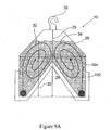
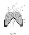
- Figures 9A-C show alternative embodiments of the present invention in which at least a portion of the bioreactor 100, in this instance the lower wall portion 102 of the bioreactor 100, is made of a plastic that is self supportive.
- the portion 102 may have a heavier, more rigid or thicker plastic film laminated to its outer (non-contact) surface 104 of the bioreactor.
- the lower portion 102 of the wall itself can be formed of one plastic material 106 and the upper portion 108 of the bioreactor wall is formed of regular plastic film and attached to the lower portion 102 by heat bonding, overmolding, adhesives and the like.
- Figure 9C shows the embodiment in which a separate stand- alone plastic support portion 110 is used to contain and support at least a portion of the bioreactor 100.
- Suitable plastics include those which can be used to make the bioreactor itself although they may be of higher molecular weight, thickness or additional layers. Additionally, they may be of more rigid plastic such as PET, polycarbonates, styrenes or other such well-known rigid plastics.
Landscapes
- Health & Medical Sciences (AREA)
- Wood Science & Technology (AREA)
- Life Sciences & Earth Sciences (AREA)
- Engineering & Computer Science (AREA)
- Bioinformatics & Cheminformatics (AREA)
- Organic Chemistry (AREA)
- Chemical & Material Sciences (AREA)
- Zoology (AREA)
- Biomedical Technology (AREA)
- Sustainable Development (AREA)
- Microbiology (AREA)
- Biochemistry (AREA)
- General Engineering & Computer Science (AREA)
- General Health & Medical Sciences (AREA)
- Genetics & Genomics (AREA)
- Biotechnology (AREA)
- Clinical Laboratory Science (AREA)
- Apparatus Associated With Microorganisms And Enzymes (AREA)
- Materials For Medical Uses (AREA)
Abstract
Description
- This invention relates to bioreactors.
- The culture of microbial cells (fermentation) or animal and plant cells (tissue culture) are commercially-important chemical and biochemical production processes. Living cells are employed in these processes because living cells, using generally easily obtainable starting materials, can economically synthesize commercially-valuable chemicals including proteins such as monoclonal antibodies or enzymes; vaccines or alcoholic beverages.
- Fermentation involves the growth or maintenance of living cells in a nutrient liquid media. In a typical batch fermentation process, the desired microorganism or eukaryotic cell is placed in a defined medium composed of water, nutrient chemicals and dissolved gases, and allowed to grow (or multiply) to a desired culture density. The liquid medium must contain all the chemicals which the cells require for their life processes and also should provide the optimal environmental conditions for their continued growth and/or replication. Currently, a representative microbial cell culture process might utilize either a continuous stirred-tank reactor or a gas-fluidized bed reactor in which the microbe population is suspended in circulating nutrient media. Similarly, in vitro mammalian cell culture might employ a suspended culture of cells in roller flasks or, for cells requiring surface attachment, cultures grown to confluence in tissue culture flasks containing nutrient medium above the attached cells. The living cells, so maintained, then metabolically produce the desired product(s) from precursor chemicals introduced into the nutrient mixture. The desired product(s) are either purified from the liquid medium or are extracted from the cells themselves.
- At the present time, the biotechnology industry has traditionally utilized stainless steel bioreactors and piping in the manufacturing process since they can be sterilized and reused. However, these systems are costly. In addition, these systems require the periodic transfers of the cell cultures as they grow with an attendant reaction volume increase during the course of the bioreaction. However, the effective reaction volume of large reactor is not linearly scalable as the culture volume increases. As a result, mixing, gas transfer and thermal conditions will change due to an increase in culture volume and the culture will not be uniformly mixed. It is therefore, necessary to transfer the cell culture to a bioreactor having a different geometry in order to attain essentially the same mixing conditions. This procedure requires the maintenance of a multiplicity of reactor sets, usually three sets with consequent increase in capital costs. In addition, the cell culture transfer conditions must be maintained to prevent cell culture contamination. This requirement adds significantly to the bioreaction costs.
- Within the linearly scalable reaction system employed, there must be included means to circulate the cell culture without dead zones within the reactor so as to effect complete bioreaction within the bioreactor. In addition, conditions under which the cells will shear must be avoided. Furthermore, means must be provided for adding nutrients, oxygen or carbon dioxide to maintain cell growth and cell viability as well as for maintaining proper desired pH. Also, care must be taken to initially sterilize and to subsequently exclude undesired cell types and cell toxins.
- One system for a bioreactor has been to use a large table, equipped with motors or hydraulics onto which a bioreactor bag is placed. The motors/hydraulics rock the bag providing constant movement of the cells. Additionally, the bag has a gas and nutrient supply tube and a waste gas and waste product tube which allow for the supply of nutrients and gases such as air for aerobic organisms and the removal of waste such as respired gases, carbon dioxide and the like. The tubes are arranged to work with the motion of the bag to allow for a uniform movement of the gases and fluids/solids. See
U.S. Pat. No. 6,190,913 . Such a system requires the use of capital-intensive equipment, with components that are susceptible to wear. Additionally, the size of the bag that can be used with the table is limited by the size of table and the lifting capability of its motors/hydraulics. - An alternative system uses a long flexible tube-like bag that has both ends attached to movable arms such that the bag after filling is suspended downwardly from the movable arm in the shape of a U. The arms are then alternately moved upward or downward relative to the other so as to cause a rocking motion and fluid movement within the bag. If desired, the midsection may contain a restriction to cause a more intimate mixing action. This system requires the use of a specifically shaped bag and hydraulic or other lifting equipment to cause the movement of the liquid. Additionally, due to weight considerations, the bag size and volume is restricted by the lifting capacity of the equipment and the strength of the bag.
- An improvement has been shown through the use of one or more bags that are capable of being selectively pressurized and deflated in conjunction with a disposable bio bag such as a fermenter, mixing bag, storage bag and the like. The pressure bag(s) may surround a selected outer portion of the bag or may be contained within an inner portion of such a bag. By selectively pressurizing and deflating the pressure bag(s), one is able to achieve fluid motion in the bag thereby ensuring cell suspension, mixing and/or gas and/or nutrient/excrement transfer within the bag without damaging shear forces or foam generation.
- Alternatively, one can select a static (non-moving) bag that contains a sparger or other device for introducing a gas into the bag. The gas causes the movement of the fluid in the bag as well to cause the mixing and transfer of gases, nutrients and waste products.
-
U.S. Pat. No. 5,565,015 uses a flat, inflatable porous tube that is sealed into a plastic container. The tube inflates under gas pressure and allows gas to flow into the bag. When the gas is not applied, the tube collapses and substantially closes off the pores of the flat tube to prevent leakage from the bag. -
U.S. Pat. No. 6,432,698 also inserts and seals a tube to a gas diffuser within the bag. It appears that a constant positive gas pressure must be maintained in order to prevent any liquid within the bag from entering the diffuser and then the gas line and eventually the air pump as no valve or other means for preventing backflow is shown. - Both of the structures disclosed by these two patents have the potential for leakage of the liquid in the container which can potentially contaminate the contents of the bag of the upstream components of the system such as the gas supply system. Additionally, both introduce a separate component for the gas distribution.
- Accordingly, it would be desirable to provide a linearly, scalable self standing bioreactor apparatus and system which eliminates the need to transfer a cell culture from a first bioreactor to a second bioreactor. Such an apparatus and system would permit the use of a constant range of bioreaction conditions within one bioreactor.
- The present invention is as claimed in the claims.
- The present invention provides a self-standing disposable bioreactor which is linearly scaleable to any desired volume. More particularly, this invention provides a bioreactor wherein its length dimension can be increased while maintaining a constant aspect ratio (width/ height) in the volume of the reactor wherein bioreaction is effected. In addition, due to the lack of fixtures required, the self standing bioreactor is flexible and can conform to different space restrictions.
- The present invention provides a disposable, self standing bioreactor which is linearly scaleable. By the term, "linearly scaleable" as used herein with reference to a bioreactor having a height, width and length is meant expandable in the length direction of the bioreactor while maintaining the aspect ratio (width/height) of the bioreactor constant. By maintaining the aspect ratio and cross sectional shape of the bioreactor constant and by increasing the length of the bioreactor over time, the mixing conditions within the bioreactor can be maintained essentially constant while increasing the effective volume of the bioreactor. This feature permits the use of one bioreactor over the full term of culture growth to produce the desired product(s). The bioreactor is rendered self standing such as by a support rod which extends through at least one loop. Optionally, at least a portion of the bioreactor is either formed of a more rigid plastic or has a more rigid plastic attached to an outer portion of the bioreactor to provide additional support.
- The bioreactor includes means for introducing gas and for removing gas. The bioreactor also includes means for adding reactants and for removing desired product(s).
- The bioreactor is formed of a flexible material such as a polymeric composition which can be folded upon itself, wound on itself or clamped on itself to form a seal. The flexible material does not contaminate the reactants or the products. Since the bioreactor is flexible, it can be bent on itself to fit into a wide variety of spaces.
- The bioreactor is formed such that it has no horizontal or substantially horizontal surface upon which the cells can deposit This may be accomplished by either using a horizontal surface which has a gas supply that forms bubbles through it so that cells are pushed away from that surface or by using an angled inner wall of the reactor or both. Preferably the angled inner wall is substantially vertical.
- The bioreactor is also shaped to affect movement of reactant liquid upwardly along an inner surface of an outer wall of the bioreactor and then downwardly within the reactant volume remote for the inner surface of the outer wall of the bioreactor.
- The bioreactor includes a first inner surface of an outer wall which forms a closed volume with a second inner surface of an inner wall of the bioreactor. The first and second inner surfaces have at least a portion thereof which converge toward each other or diverge away from each other so that movement of reactant liquid within the bioreactor is in an essentially spiral direction under the influence of gases introduced into the bioreactor.
- Embodiments of the invention will now be described, by way of example only, with reference to the accompanying drawings of which:
-
Figure 1 is a diagrammatic isometric view of a bioreactor according to the present invention; -
Figure 2 is a diagrammatic illustration the steps of expanding the bioreactor ofFigure 1 ; -
Figure 3 is a diagrammatic cross sectional view of a bioreactor of which includes the width and height of the effective bioreaction volume; -
Figure 4 is a diagrammatic isometric view of an alternative embodiment of the present invention; -
Figure 5 is a diagrammatic isometric view illustrating the use of clamps with the illustrated embodiments of this invention; -
Figure 6 is a diagrammatic isometric view of a further bioreactor of the present invention utilizing clamps; -
Figure 7 is a diagrammatic cross sectional view of a further bioreactor of the present invention; -
Figure 8 is a diagrammatic cross sectional view of a further bioreactor of the present invention; and -
Figures 9A-C show cross sectional views of further embodiments of the present invention. - In accordance with this invention, a disposable, expandable bioreactor is provided having a constant aspect ratio and constant cross section which includes its height and width wherein the bioreactor's effective volume is increased by increasing its length. The bioreactor initially has a relatively small effective volume into which a cell culture, nutrients and one or more gases are introduced to effect a bioreaction therein. By the term "effective volume" as used herein is meant the bioreactor volume wherein reaction occurs. A portion of the bioreactor volume comprises a gas containing volume positioned above the effective volume. When it is desired to increase the bioreactor effective volume, an expandable portion of the bioreactor is expanded. The expansion is in a direction to increase the length of the bioreactor thereby to increase the effective volume of the bioreactor. Since the cross section including the width and height of the bioreactor is maintained constant over the course of the expansion, the reaction conditions can be maintained constant over the course of bioreactor expansion since the mixing conditions can be maintained constant. This is because the circulation of reactants caused by introducing gases is the same within the bioreactor cross section regardless of position on the length dimension. The bioreactor is self standing despite being formed of a flexible material since it is supported such as on one or more hooks or by one or more rods that extend through loops positioned at the top of the bioreactor.
- The bioreactor length can be increased in any manner. Thus, the end of the bioreaction not in current use can be unfolded, or unwound. In addition, the unused portion of the bioreactor can be separated from the currently used effective volume by one or more clamps which can be removed in series to obtain a desired effective volume over time. The bioreactor volumes could also be increased sequentially when the unused volumes are pleated or rolled up in the manner described below with reference to
Figures 2 and4 . - The internal volume of the bioreactor is shaped so that the reactants are satisfactorily mixed together in all portions of the effective volume. Thus, dead zones where little or no mixing occurs are avoided. A volume external the bioreactor is provided to house a heater which controls temperature within the bioreactor. One or more inlets to the bioreactor are provided for the purpose of introducing reactants into the bioreactor or to remove products from the bioreactor.
- The bioreactor is formed such that it has no horizontal or substantially horizontal surface upon which the cells can deposit This may be accomplished by either using a horizontal surface which has a gas supply that forms bubbles through it so that cells are pushed away from that surface or by using an angled inner wall of the reactor or both. Preferably, the angled inner wall is substantially vertical.
- One embodiment of this design is a reactor having two legs connected to each other by a bridge section that is between the two legs where the two legs join such as I sshown in
Figures 1-7 or a rounded or ovular reactor wall shape as shown inFigure 8 . Additionally the horizontal surface having the gas supply can be a porous filter or membrane as shown inFigures 7 and8 or it may contain one or more spargers or other gas porous gas supply devices which pass the gas into the liquid as shown inFigures 1-6 and in both designs the gas either entrains the cells with its upward motion or it pushes the cells upward as it passes into the liquid. - The bioreactor is also shaped to affect movement of reactant liquid upwardly along an inner surface of an outer wall of the bioreactor and then downwardly within the reactant volume remote for the inner surface of the outer wall of the bioreactor.
- The bioreactor includes a first inner surface of an outer wall which forms a closed volume with a second inner surface of an inner wall of the bioreactor. The first and second inner surfaces have at least a portion thereof which converge toward each other or diverge away from each other so that movement of reactant liquid within the bioreactor is in an essentially spiral direction under the influence of gases introduced into the bioreactor.
- Gas is introduced into the effective volume of the bioreactor by at least one porous passage which can be formed integrally with the bioreactor such as by being adhered thereto along the length of the bioreactor. Alternatively, the porous passages can be formed separately from the bioreactor such as a sparger tube and can be progressively inserted into the reactor when the effective volume of the reactor is increased. Conventional sealing means are provided to prevent leakage from the bioreactor at the areas where the porous passages are inserted into the reactor. The porous passages can be formed of a flexible material such as a polymeric composition which does not contaminate the reactants or product(s) or a rigid porous material such as a ceramic, a glass, such as a glass mat or a sintered glass material or sintered stainless steel which does not contaminate the reactants or product(s).
- Suitable plastics can be hydrophilic or hydrophobic. When hydrophilic however one must ensure that the air pressure within the passage is either constantly at or above that of the liquid intrusion pressure so as to keep the liquid out of the passage or to provide an upstream shutoff such as a valve or hydrophobic filter to prevent the liquid in the bioreactor from flooding the passage and /or upstream gas supply. Plastics can be inherently hydrophilic or hydrophobic or can be surface treated to provide the desired properties. The plastics may be a single layer or if desired, multilayered. One example of a multilayered passage has a porous plastic layer covered by a more open prefilter or depth filter that can trap any debris and keep the debris from clogging the porous passage(s). The pore size or sizes selected depends upon the size of gas bubble desired. The pore size may range from microporous (0.1 to 10 microns) to macroporous (greater than 10 microns) and it may be formed of membranes or filters such as a microporous filter, woven fabrics or filters, porous non-woven materials, such as Tyvek® sheet materials, monoliths or pads, such as can be found in many aquarium filters and the like. The selected plastic(s) should be compatible with the bioreactor environment so it doesn't adversely affect the cells being grown within it. Suitable plastics include but are not limited to polyolefins such as polyethylene or polypropylene, polysulfones such as polysulfone or polyethersulfone, nylons, PTFE resin, PEF, PVDF, PET and the like.
- The introduced gas functions both as a reactant and as a means for mixing the reactants.
- Referring to
Figure 1 , thebioreactor 10 includes twolegs legs gas volume 18 is provided above section 16 where unreacted introduced gas is collected. The gas is introduced intobioreactor 10 throughpassages Inlets external volume 24 is shaped to house a heater (not shown) for controlling the temperature within thebioreactor 10. Thebioreactor 10 includes loops or hooks 35 through which supportingrod 37 extends to render thebioreactor 10 self standing. - As shown in
Figure 3 , the cross section of theinternal volume 26 containing thewidth 28 and theheight 29 is constant throughout the length of thebioreactor 10.Height 30 is the height of the effective volume which changes slightly with reactant addition or product removal. Theheight 30 of the effective volume can be maintained essentially constant by controlling the degree the effective volume is expanded, the volume of nutrients added and the volume of products removed. Thus, mixing conditions, as represented byarrows bioreactor 10 even after effective volume increase. - Referring to
Figure 2 , a sequence of bioreactor expansion steps is illustrated. In a first step,bioreactor 10 A is shown wherein a first step of the bioreaction is effected. Aportion 39 of the bioreactor is folded upon itself. In a second step, a portion of the foldedportion 39 is unfolded to expand thebioreactor 10 A along its length to formbioreactor 10 B wherein a second step of the bioreaction is effected. In a third step, the foldedportion 39 is unfolded to expand thebioreactor 10 B along its length to formbioreactor 10 C wherein a third step of the bioreaction is effected. As shown, the cross section of the bioreactors containing the maximum width and height of thebioreactor bioreactor 10 C can be disposed. - Referring to
Figure 4 , an alternative configuration of thebioreactor 11 of this invention is shown. Thebioreactor 11 is constructed essentially the same asbioreactor 10 A (Figure 2 ) except that theunexpanded portion 41 is wound upon itself rather than being folded upon itself Theunexpanded portion 41 is unwound a desired length during the course of the desired bioreaction. In use, the bioreactor is utilized in the manner exemplified by the illustration ofFigure 2 and, upon completion of the bioreaction and recovery of the products can be discarded at acceptable cost. - Referring to
Figure 5 , thebioreactor 13 having the same configuration as the bioreactor ofFigure 1 is segmented intoseparate volumes clamps bioreactor 13,clamp 43 is released to combinevolumes bioreactor 13,clamp 45 is released to combinevolumes volumes Figure 5 , the bioreactor can be bent on itself in order to better utilize the space of a building in which the bioreactor is housed. The bioreactor ofFigure 5 permits the use of a more rapid process for effecting bioreaction. Initial bioreactions can be affected simultaneously involumes volumes volumes volumes volumes - Referring to
Figure 6 , thebioreactor 49 includesvolumes volumes bioreactor 49, clamps 53, 55, 57, 63, 65 and 67 are released to combinevolumes volume 58 and to combinevolumes volume 60 to affect secondary bioreactions. When it is desired to further increase the effective volume ofbioreactor 49, clamps 59 and 61 are released to combine all thevolumes Figure 6 permits the use of a more rapid process for effecting bioreaction since initial bioreactions can be effected simultaneously in six volumes which then can be combined with additional volumes sequentially.Volumes - Alternatively, the bioreaction can be effected sequentially by starting in one volume, such as
volume 50 and then progress in size by opening one or moreadditional volumes - Referring to
Figure 7 , thebioreactor 70 is formed of a flexible material and has an expandable length in the manner described above with reference toFigures 1-6 . Thelegs section 76 positioned belowlegs porous passage 78 positioned withinsection 76. Twoheaters bioreactor 70 and also provide support forbioreactor 70. Thebioreactor 70 is also supported byrods - Referring to
Figure 8 , thebioreactor 81 is formed of a flexible material and has an expandable length in the manner described above with reference toFigures 1-6 . Theinlets volume 84 positioned abovevolume 86 through which gas enters thebioreactor 81. The gas passes through gaspermeable membrane 88 in a controlled manner so as to avoid rupturing the cells therein. Asecond membrane 90 is positioned below thesurface 92 of the reactants so as to control gas passing therethrough in order to avoid foaming of the reactants and to avoid rupturing the cells. - The bioreactor of this invention can be formed of a flexible plastic material. Preferably thermoplastics are used and include but are not limited, polyolefins homopolymers such as polyethylene and polypropylene, polyolefins copolymers, nylons, ethylene vinyl acetate copolymers (EVA copolymers), ethylene vinyl alcohols (EVOH) and the like. Multilayered films or sheets are preferably used as the bioreactor materials and are generally made of several layers of polyethylene or polypropylene, such as linear low density polyethylene with other layers such as ethylene vinyl acetate copolymers and ethylene vinyl alcohols that are used to adhere layers together and/or to block gas transfer out of the bioreactor. It is preferred that the plastic be transparent so the activity within can be conducted by visual inspection.
-
Figures 9A-C show alternative embodiments of the present invention in which at least a portion of the bioreactor 100, in this instance thelower wall portion 102 of the bioreactor 100, is made of a plastic that is self supportive. For example, inFigure 9A theportion 102 may have a heavier, more rigid or thicker plastic film laminated to its outer (non-contact) surface 104 of the bioreactor. Alternatively, inFigure 9B , thelower portion 102 of the wall itself can be formed of oneplastic material 106 and theupper portion 108 of the bioreactor wall is formed of regular plastic film and attached to thelower portion 102 by heat bonding, overmolding, adhesives and the like.Figure 9C shows the embodiment in which a separate stand- aloneplastic support portion 110 is used to contain and support at least a portion of the bioreactor 100. - Suitable plastics include those which can be used to make the bioreactor itself although they may be of higher molecular weight, thickness or additional layers. Additionally, they may be of more rigid plastic such as PET, polycarbonates, styrenes or other such well-known rigid plastics.
Claims (13)
- A self standing bioreactor formed of a flexible material having a constant aspect ratio and an adjustable length and including a support means to support the bioreactor.
- A bioreactor formed of a flexible material, having an internal volume including two leg sections joined by a bridge section, means for introducing gas into each of said leg sections, means for introducing gas into said leg sections along the length of said leg sections, means for introducing reactants into said bioreactor, means for removing product from said bioreactor, said bioreactor having a constant aspect ratio and an adjustable length and at least one supporting rod extending through a device selected from the group consisting of loops and hooks on the bioreactor to support the bioreactor.
- The bioreactor of Claim 1 or 2 wherein said length is adjustable by unfolding a length of folded bioreactor.
- The bioreactor of Claim 1 or 2 wherein said length is adjustable by unwinding a length of wound bioreactor.
- The bioreactor of Claim 1 or 2 wherein said length is adjustable by releasing one or a plurality of clamps positioned along the length of said bioreactor.
- The bioreactor of any preceding claim supported by a plurality of rods.
- The bioreactor of claim 2 wherein said bridge is positioned above said leg sections.
- The bioreactor of any preceding claim wherein the bioreactor is formed such that it has no horizontal or substantially horizontal surface upon which the cells can deposit.
- The bioreactor of any preceding claim further comprising an external volume shaped to house a heater for controlling the temperature within the bioreactor.
- The bioreactor of any preceding claim wherein the support means includes loops or hooks.
- The bioreactor of claim 10, the support means further including a supporting rod.
- The bioreactor of claim 1 or 2 wherein the bioreactor has a series of volumes and clamps that close off one or more of the series of volumes until it is desired to increase the effective volume of bioreactor.
- The bioreactor of claim 2 wherein the bioreactor has a series of volumes closed off from one another and the volumes can be opened to one another sequentially as needed.
Applications Claiming Priority (1)
| Application Number | Priority Date | Filing Date | Title |
|---|---|---|---|
| US85907706P | 2006-11-15 | 2006-11-15 |
Publications (1)
| Publication Number | Publication Date |
|---|---|
| EP1923459A1 true EP1923459A1 (en) | 2008-05-21 |
Family
ID=38984069
Family Applications (1)
| Application Number | Title | Priority Date | Filing Date |
|---|---|---|---|
| EP07254451A Withdrawn EP1923459A1 (en) | 2006-11-15 | 2007-11-14 | A bioreactor |
Country Status (5)
| Country | Link |
|---|---|
| US (1) | US20080131960A1 (en) |
| EP (1) | EP1923459A1 (en) |
| JP (1) | JP2008212142A (en) |
| CN (1) | CN101255395A (en) |
| SG (1) | SG143161A1 (en) |
Cited By (2)
| Publication number | Priority date | Publication date | Assignee | Title |
|---|---|---|---|---|
| CN102648044A (en) * | 2009-05-05 | 2012-08-22 | 拜尔技术服务有限责任公司 | Apparatus for culturing cells and/or microorganisms |
| ITVR20130157A1 (en) * | 2013-07-05 | 2015-01-06 | Francesco Campostrini | PLANT FOR CULTIVATION OF PHOTOSYNTHETIC MICROORGANISMS, MIXED CROPS OF PHOTOSYNTHETIC AND NON-PHOTOSYNTHETIC MICRO-ORGANISMS AND / OR VEGETABLE CELLS. |
Families Citing this family (17)
| Publication number | Priority date | Publication date | Assignee | Title |
|---|---|---|---|---|
| US20070048859A1 (en) * | 2005-08-25 | 2007-03-01 | Sunsource Industries | Closed system bioreactor apparatus |
| US20110076756A1 (en) * | 2007-01-22 | 2011-03-31 | Ian Malcolm Wright | variable volume bioreactor |
| WO2009152175A1 (en) * | 2008-06-09 | 2009-12-17 | Solix Biofuels, Inc. | Permeable membranes in film photobioreactors |
| DE102010027708A1 (en) * | 2010-07-20 | 2012-01-26 | Michael Fuderer | Foil, supporting structure, supply device, bioreactor and method for cultivating microorganisms |
| CN102787072B (en) * | 2012-04-28 | 2014-05-21 | 郑州威瑞生物技术有限公司 | Soft membrane bioreactor |
| CN104995029B (en) * | 2013-01-18 | 2017-05-24 | 赛多利斯斯泰迪姆Fmt有限公司 | Multilayer film comprising a core layer and an outer layer for the wall of a single-use pouch |
| WO2014111549A1 (en) | 2013-01-18 | 2014-07-24 | Sartorius Stedim Fmt Sas | Multilayer film comprising a core layer and an outer layer for the wall of a single-use pouch |
| DE102013001444B4 (en) * | 2013-01-29 | 2014-12-18 | Pateffect Schutzrechtsmanagement Gbr (Vertretungsberechtigte Gesellschafter: Dr. Volker Linden, 73430 Aalen Und Klaus Kunze, 88250 Weingarten) | bioreactor suspension |
| AU2013392951B2 (en) * | 2013-06-18 | 2016-04-14 | Ecogas Israel Ltd | Lightweight assemblable appliance and respective method for production of biogas and liquid fertilizer |
| WO2019003075A1 (en) | 2017-06-25 | 2019-01-03 | Home Biogas Ltd | Lightweight appliance with exoskeletal support respective kit-of-parts and method for production of biogas and liquid fertilizer |
| US20180072978A1 (en) * | 2015-03-20 | 2018-03-15 | Sekisui Chemical Co., Ltd. | Microorganism culture method and culture apparatus |
| JP6629356B2 (en) * | 2015-03-23 | 2020-01-15 | イー・エム・デイー・ミリポア・コーポレイシヨン | Abrasion resistant film for biocontainers |
| US10975538B2 (en) * | 2016-06-13 | 2021-04-13 | Rsa Protective Technologies, Llc | Method and system for a retractable floodwall system |
| CN109415670A (en) * | 2016-07-05 | 2019-03-01 | 通用电气公司 | Apparatus and method for volume-adjustable cell culture |
| WO2021114087A1 (en) * | 2019-12-10 | 2021-06-17 | 苏州生动细胞生物科技有限公司 | Small-volume cell culture bag |
| EP3872053B1 (en) * | 2020-02-28 | 2023-09-27 | MICO-Systems GmbH | Extraction device and extraction method for fermentation medium |
| CN116218659A (en) * | 2023-04-04 | 2023-06-06 | 中国科学院天津工业生物技术研究所 | A solid-state bioreactor and a solid-state culture method for microorganisms |
Citations (5)
| Publication number | Priority date | Publication date | Assignee | Title |
|---|---|---|---|---|
| US5453376A (en) | 1994-01-14 | 1995-09-26 | Ek; J. Edwin | Compost chamber |
| US5507133A (en) * | 1994-02-07 | 1996-04-16 | University Of Hawaii | Inoculant method and apparatus |
| WO1998013469A1 (en) * | 1996-09-26 | 1998-04-02 | Metabogal Ltd. | Cell/tissue culturing device and method |
| WO2003094598A1 (en) | 2002-05-13 | 2003-11-20 | Greenfuel Technologies Corporation | Photobioreactor and process for biomass production and mitigation of pollutants in flue gases |
| DE102004007564A1 (en) * | 2004-02-17 | 2005-09-01 | Cordes, Rudolf, Dipl.-Ing. | Device for breeding and mass production of algae |
Family Cites Families (17)
| Publication number | Priority date | Publication date | Assignee | Title |
|---|---|---|---|---|
| US2732663A (en) * | 1956-01-31 | System for photosynthesis | ||
| CH509234A (en) * | 1969-07-10 | 1971-06-30 | Ceskoslovenska Akademie Ved | Device for the biological purification of organically polluted water |
| US4291499A (en) * | 1979-08-14 | 1981-09-29 | Prewer John R | Propagation of plants |
| US5017490A (en) * | 1989-03-10 | 1991-05-21 | Baxter International Inc. | Method for in vitro reproduction and growth of cells in culture medium |
| JPH05219834A (en) * | 1992-02-14 | 1993-08-31 | Fumiko Kobayashi | Disposable culture bag and culture process |
| JPH0613499U (en) * | 1992-07-24 | 1994-02-22 | 積水化学工業株式会社 | Culture vessel |
| US5443985A (en) * | 1993-07-22 | 1995-08-22 | Alberta Research Council | Cell culture bioreactor |
| US20050032211A1 (en) * | 1996-09-26 | 2005-02-10 | Metabogal Ltd. | Cell/tissue culturing device, system and method |
| US6190913B1 (en) * | 1997-08-12 | 2001-02-20 | Vijay Singh | Method for culturing cells using wave-induced agitation |
| US6432698B1 (en) * | 1999-01-06 | 2002-08-13 | Rutgers, The State University | Disposable bioreactor for culturing microorganisms and cells |
| JP3641156B2 (en) * | 1999-03-15 | 2005-04-20 | 株式会社東芝 | New microorganisms and biological treatment methods for marine organisms |
| GB9924087D0 (en) * | 1999-10-12 | 1999-12-15 | Maltin Christopher | Treatment of process fluids |
| US7033823B2 (en) * | 2002-01-31 | 2006-04-25 | Cesco Bioengineering, Inc. | Cell-cultivating device |
| US7229820B2 (en) * | 2002-06-13 | 2007-06-12 | Wilson Wolf Manufacturing Corporation | Apparatus and method for culturing and preserving tissue constructs |
| GB2433266A (en) * | 2005-12-16 | 2007-06-20 | Kevin Andrew Auton | Cell culture vessel |
| US20070224676A1 (en) * | 2006-03-21 | 2007-09-27 | Becton, Dickinson And Company | Expandable culture roller bottle |
| WO2008055190A2 (en) * | 2006-11-02 | 2008-05-08 | Algenol Biofuels Limited | Closed photobioreactor system for production of ethanol |
-
2007
- 2007-10-30 US US11/978,913 patent/US20080131960A1/en not_active Abandoned
- 2007-11-09 SG SG200717622-5A patent/SG143161A1/en unknown
- 2007-11-14 JP JP2007295729A patent/JP2008212142A/en active Pending
- 2007-11-14 CN CNA2007101698701A patent/CN101255395A/en active Pending
- 2007-11-14 EP EP07254451A patent/EP1923459A1/en not_active Withdrawn
Patent Citations (5)
| Publication number | Priority date | Publication date | Assignee | Title |
|---|---|---|---|---|
| US5453376A (en) | 1994-01-14 | 1995-09-26 | Ek; J. Edwin | Compost chamber |
| US5507133A (en) * | 1994-02-07 | 1996-04-16 | University Of Hawaii | Inoculant method and apparatus |
| WO1998013469A1 (en) * | 1996-09-26 | 1998-04-02 | Metabogal Ltd. | Cell/tissue culturing device and method |
| WO2003094598A1 (en) | 2002-05-13 | 2003-11-20 | Greenfuel Technologies Corporation | Photobioreactor and process for biomass production and mitigation of pollutants in flue gases |
| DE102004007564A1 (en) * | 2004-02-17 | 2005-09-01 | Cordes, Rudolf, Dipl.-Ing. | Device for breeding and mass production of algae |
Cited By (4)
| Publication number | Priority date | Publication date | Assignee | Title |
|---|---|---|---|---|
| CN102648044A (en) * | 2009-05-05 | 2012-08-22 | 拜尔技术服务有限责任公司 | Apparatus for culturing cells and/or microorganisms |
| CN102648044B (en) * | 2009-05-05 | 2015-02-11 | 拜耳知识产权有限责任公司 | Apparatus for culturing cells and/or microorganisms |
| ITVR20130157A1 (en) * | 2013-07-05 | 2015-01-06 | Francesco Campostrini | PLANT FOR CULTIVATION OF PHOTOSYNTHETIC MICROORGANISMS, MIXED CROPS OF PHOTOSYNTHETIC AND NON-PHOTOSYNTHETIC MICRO-ORGANISMS AND / OR VEGETABLE CELLS. |
| WO2015001530A3 (en) * | 2013-07-05 | 2015-04-23 | Campostrini Francesco | Photobioreactor plant for cultivating photosynthetic microorganisms |
Also Published As
| Publication number | Publication date |
|---|---|
| JP2008212142A (en) | 2008-09-18 |
| SG143161A1 (en) | 2008-06-27 |
| US20080131960A1 (en) | 2008-06-05 |
| CN101255395A (en) | 2008-09-03 |
Similar Documents
| Publication | Publication Date | Title |
|---|---|---|
| US20080131960A1 (en) | Self standing bioreactor construction | |
| EP1923460A1 (en) | A bioreactor | |
| US12351788B2 (en) | Methods and systems for culturing microbial and cellular seed cultures | |
| AU2016397306B2 (en) | A bioreactor system and method thereof | |
| EP1602715B1 (en) | Disposable bioreactor | |
| EP1871866B1 (en) | Gas spargers and related container systems | |
| CN108315256B (en) | Active aeration component, active aeration bioreactor and cell culture device | |
| US20220348856A1 (en) | Substrates for High-Density Cell Growth and Metabolite Exchange | |
| JPH03504925A (en) | Device to oxygenate the culture medium | |
| US20130115588A1 (en) | Integrated bioreactor and separation system and methods of use therof | |
| CN102057033B (en) | Scalable cell culture bioreactor and cell culture process | |
| US20040159616A1 (en) | Flexible disposable vessel | |
| JPH0463584A (en) | Bioreactor equipment | |
| CN101120083A (en) | Method and device for cell culture by using air-permeable material | |
| EP1923461A1 (en) | A bioreactor | |
| EP0217848A1 (en) | Reactor for cultivating biological material such as immobilised cells. | |
| IES20070543A2 (en) | An airlift bioreactor | |
| AU778141B2 (en) | Method for cultivating cells, a membrane module, utilization of a membrane module and reaction system for cultivation of said cells | |
| US20080138891A1 (en) | Small scale cell culture container | |
| JPH01225475A (en) | Culture apparatus | |
| JP2008178389A (en) | Small-scaled cell culture container |
Legal Events
| Date | Code | Title | Description |
|---|---|---|---|
| PUAI | Public reference made under article 153(3) epc to a published international application that has entered the european phase |
Free format text: ORIGINAL CODE: 0009012 |
|
| AK | Designated contracting states |
Kind code of ref document: A1 Designated state(s): AT BE BG CH CY CZ DE DK EE ES FI FR GB GR HU IE IS IT LI LT LU LV MC MT NL PL PT RO SE SI SK TR |
|
| AX | Request for extension of the european patent |
Extension state: AL BA HR MK RS |
|
| 17P | Request for examination filed |
Effective date: 20080917 |
|
| 17Q | First examination report despatched |
Effective date: 20081017 |
|
| R17C | First examination report despatched (corrected) |
Effective date: 20081104 |
|
| AKX | Designation fees paid |
Designated state(s): AT BE BG CH CY CZ DE DK EE ES FI FR GB GR HU IE IS IT LI LT LU LV MC MT NL PL PT RO SE SI SK TR |
|
| STAA | Information on the status of an ep patent application or granted ep patent |
Free format text: STATUS: THE APPLICATION IS DEEMED TO BE WITHDRAWN |
|
| 18D | Application deemed to be withdrawn |
Effective date: 20120601 |