EP1923263A1 - Integral rear lamp - Google Patents
Integral rear lamp Download PDFInfo
- Publication number
- EP1923263A1 EP1923263A1 EP07120760A EP07120760A EP1923263A1 EP 1923263 A1 EP1923263 A1 EP 1923263A1 EP 07120760 A EP07120760 A EP 07120760A EP 07120760 A EP07120760 A EP 07120760A EP 1923263 A1 EP1923263 A1 EP 1923263A1
- Authority
- EP
- European Patent Office
- Prior art keywords
- lamp
- integral rear
- rear lamp
- elements
- reflector
- Prior art date
- Legal status (The legal status is an assumption and is not a legal conclusion. Google has not performed a legal analysis and makes no representation as to the accuracy of the status listed.)
- Withdrawn
Links
Images


Classifications
-
- B—PERFORMING OPERATIONS; TRANSPORTING
- B60—VEHICLES IN GENERAL
- B60Q—ARRANGEMENT OF SIGNALLING OR LIGHTING DEVICES, THE MOUNTING OR SUPPORTING THEREOF OR CIRCUITS THEREFOR, FOR VEHICLES IN GENERAL
- B60Q1/00—Arrangement of optical signalling or lighting devices, the mounting or supporting thereof or circuits therefor
- B60Q1/26—Arrangement of optical signalling or lighting devices, the mounting or supporting thereof or circuits therefor the devices being primarily intended to indicate the vehicle, or parts thereof, or to give signals, to other traffic
- B60Q1/2607—Arrangement of optical signalling or lighting devices, the mounting or supporting thereof or circuits therefor the devices being primarily intended to indicate the vehicle, or parts thereof, or to give signals, to other traffic comprising at least two indicating lamps
-
- B—PERFORMING OPERATIONS; TRANSPORTING
- B60—VEHICLES IN GENERAL
- B60Q—ARRANGEMENT OF SIGNALLING OR LIGHTING DEVICES, THE MOUNTING OR SUPPORTING THEREOF OR CIRCUITS THEREFOR, FOR VEHICLES IN GENERAL
- B60Q1/00—Arrangement of optical signalling or lighting devices, the mounting or supporting thereof or circuits therefor
- B60Q1/26—Arrangement of optical signalling or lighting devices, the mounting or supporting thereof or circuits therefor the devices being primarily intended to indicate the vehicle, or parts thereof, or to give signals, to other traffic
- B60Q1/30—Arrangement of optical signalling or lighting devices, the mounting or supporting thereof or circuits therefor the devices being primarily intended to indicate the vehicle, or parts thereof, or to give signals, to other traffic for indicating rear of vehicle, e.g. by means of reflecting surfaces
- B60Q1/302—Arrangement of optical signalling or lighting devices, the mounting or supporting thereof or circuits therefor the devices being primarily intended to indicate the vehicle, or parts thereof, or to give signals, to other traffic for indicating rear of vehicle, e.g. by means of reflecting surfaces mounted in the vicinity, e.g. in the middle, of a rear window
-
- B—PERFORMING OPERATIONS; TRANSPORTING
- B60—VEHICLES IN GENERAL
- B60Q—ARRANGEMENT OF SIGNALLING OR LIGHTING DEVICES, THE MOUNTING OR SUPPORTING THEREOF OR CIRCUITS THEREFOR, FOR VEHICLES IN GENERAL
- B60Q1/00—Arrangement of optical signalling or lighting devices, the mounting or supporting thereof or circuits therefor
- B60Q1/26—Arrangement of optical signalling or lighting devices, the mounting or supporting thereof or circuits therefor the devices being primarily intended to indicate the vehicle, or parts thereof, or to give signals, to other traffic
- B60Q1/2696—Mounting of devices using LEDs
-
- F—MECHANICAL ENGINEERING; LIGHTING; HEATING; WEAPONS; BLASTING
- F21—LIGHTING
- F21S—NON-PORTABLE LIGHTING DEVICES; SYSTEMS THEREOF; VEHICLE LIGHTING DEVICES SPECIALLY ADAPTED FOR VEHICLE EXTERIORS
- F21S43/00—Signalling devices specially adapted for vehicle exteriors, e.g. brake lamps, direction indicator lights or reversing lights
- F21S43/10—Signalling devices specially adapted for vehicle exteriors, e.g. brake lamps, direction indicator lights or reversing lights characterised by the light source
- F21S43/13—Signalling devices specially adapted for vehicle exteriors, e.g. brake lamps, direction indicator lights or reversing lights characterised by the light source characterised by the type of light source
- F21S43/14—Light emitting diodes [LED]
-
- B—PERFORMING OPERATIONS; TRANSPORTING
- B60—VEHICLES IN GENERAL
- B60Q—ARRANGEMENT OF SIGNALLING OR LIGHTING DEVICES, THE MOUNTING OR SUPPORTING THEREOF OR CIRCUITS THEREFOR, FOR VEHICLES IN GENERAL
- B60Q2400/00—Special features or arrangements of exterior signal lamps for vehicles
- B60Q2400/20—Multi-color single source or LED matrix, e.g. yellow blinker and red brake lamp generated by single lamp
Definitions
- This invention relates to an integral rear lamp according to Claim 1
- Integral rear lamps are used in the first place to make a wide variety of vehicles clearly visible to following traffic, particularly in darkness, and secondly to give different signals to following vehicles through light signals.
- Integral rear lamps therefore generally incorporate a plurality of luminous surfaces in different colours, in most cases white, yellow or red, which are actively illuminated by luminous elements in the integral rear lamp, as well as a passive reflector in certain designs.
- An integral rear lamp of prior art ( Flexible Lamps Ltd., Catalogue 2003-2004, page 4, Model 800 ) incorporates, for example, an end outline marker, stop light, direction indicator, reverse, fog and tail functions and an integral reflex triangle, as prescribed for towed vehicles.
- the light elements are also constructed here as bulbs which are fed via the on-board mains of the vehicle, in most case with 24V or 12V d.c. voltage.
- a model 756 can now also be found on the Internet under "Flexible Lamps” ( www.flexible-lamps.co.uk/Catalogue/Products/756.htm ) in different designs.
- This model uses light emitting diodes, abbreviated to LED, instead of the bulbs previously used.
- LED light emitting diodes
- the advantage of these LED's is that they consume less electrical power with the same light intensity, i.e. LED's have a higher efficiency in terms of the conversion of electrical energy to light power and a longer life.
- the object of this invention is therefore to provide an integral rear light which can be used in a variable manner for different applications and is also compact in terms of its dimensions and can be manufactured under favourable conditions, as well as ensuring good visibility from different directions of vision.
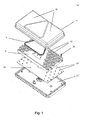
- FIG. 1 shows integral rear lamp 10 consisting of upper housing section 12, reflector 14, reflector module 16, lamp module 18 and lower housing section 20.
- Lamp module 18, with luminous elements 28 and reflector module 16 are fastened to lower housing section 20 by means of a plurality of connecting elements 24.
- Upper housing section 12 with reflector 14 is connected to the component comprising reflector module 16, lamp module 18 and lower housing section 20, for example by means of a snap connection.
- the reflector has the shape of a triangle whose vertex is at the top, as prescribed for towed vehicles such as trailers or semitrailers.
- Luminous elements 28 are constructed preferably as LED ' s, which consume much less energy with the same light yield than conventional bulbs.
- Reflectors 22 are preferably arranged close together or slightly overlapping on reflector module 16 to obtain as uniform an illumination of the entire single-part or multi-part luminous surface 38 as possible.
- luminous elements 28 are actuated by an electronic circuit which is preferably installed in the region behind reflector 14 so that it does not interrupt luminous surface 38.
- the electronic circuit is preferably installed in the region between lamp module 18 and lower housing section 20. In such a design the overall height of integral rear lamp 10 may be made slightly larger.
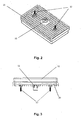
- FIG. 2 shows lower housing section 20, preferably with a plurality of fastening elements 30 which enable integral rear lamp 10 to be fastened to different types of vehicles.
- Lower housing section 20 also contains a connecting element 32, which is preferably designed as a plug connection for a standardised connecting cable. Integral rear lamp 10 is supplied with electrical energy and control signals via this connection 32.
- FIGS 3 and 4 show the integral rear light in two further views.
- Figure 5 shows the front side of integral rear lamp 10 with the arrangement of reflector 14 and a multiplicity of reflectors 22, which allow as uniform an illumination of luminous surface 38 as possible.
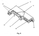
- Figures 6 to 8 show integral rear light 10 in different sectional views.
- control elements 34 in upper housing section 12 can be seen next to the elements already described, which control elements are used to influence the distribution of light over luminous surface 38.
- the illumination can be rendered more uniform thereby and visibility improved if one does not look vertically at luminous surface 38.
- cooling elements 36 can be seen which are here designed as cooling ribs and serve to ensure better discharge of the heat loss from the electrical and electronic components of integral rear lamp 10.
Landscapes
- Engineering & Computer Science (AREA)
- Mechanical Engineering (AREA)
- Physics & Mathematics (AREA)
- Microelectronics & Electronic Packaging (AREA)
- Optics & Photonics (AREA)
- General Engineering & Computer Science (AREA)
- Non-Portable Lighting Devices Or Systems Thereof (AREA)
- Lighting Device Outwards From Vehicle And Optical Signal (AREA)
Abstract
characterized in that
the different functions are converted by a single- or multi-part multifunctional luminous surface (38) by a suitable selection and/or actuation of the existing lamp elements (28).
Description
- This invention relates to an integral rear lamp according to Claim 1
- Integral rear lamps are used in the first place to make a wide variety of vehicles clearly visible to following traffic, particularly in darkness, and secondly to give different signals to following vehicles through light signals.
- Integral rear lamps therefore generally incorporate a plurality of luminous surfaces in different colours, in most cases white, yellow or red, which are actively illuminated by luminous elements in the integral rear lamp, as well as a passive reflector in certain designs.
- An integral rear lamp of prior art (Flexible Lamps Ltd., Catalogue 2003-2004, page 4, Model 800) incorporates, for example, an end outline marker, stop light, direction indicator, reverse, fog and tail functions and an integral reflex triangle, as prescribed for towed vehicles.
- As in most of the designs of prior art, the light elements are also constructed here as bulbs which are fed via the on-board mains of the vehicle, in most case with 24V or 12V d.c. voltage.
- A model 756 can now also be found on the Internet under "Flexible Lamps" (www.flexible-lamps.co.uk/Catalogue/Products/756.htm) in different designs. This model uses light emitting diodes, abbreviated to LED, instead of the bulbs previously used. The advantage of these LED's is that they consume less electrical power with the same light intensity, i.e. LED's have a higher efficiency in terms of the conversion of electrical energy to light power and a longer life.
- The disadvantage of such prior art technique is that a separate luminous surface is required for each function, i.e. one surface for the end outline marker, another one for the direction indicator, etc. A flexible arrangement of the luminous surfaces is not possible, and separate variants are produced for different requirements. Among other things there is a variant for both the left and right side of the vehicle. Moreover, this lamp is very large in terms of dimensions because of the multiplicity of luminous surfaces, and is expensive to manufacture because of the large number of LED's. The light of the LED's is preferably clustered in one direction by the reflectors.
- The object of this invention is therefore to provide an integral rear light which can be used in a variable manner for different applications and is also compact in terms of its dimensions and can be manufactured under favourable conditions, as well as ensuring good visibility from different directions of vision.
- This object is achieved according to the invention by a device with the features of Claim 1.
- Further details, features and advantages are given in the following description of an exemplary embodiments of an integral rear lamp shown in the drawings, as well as in the associated claims.
- Fig. 1 shows a perspective exploded view of an integral rear lamp
- Fig. 2 shows a perspective view of the rear side of the integral rear lamp
- Fig. 3 shows a view of the integral rear lamp from below
- Fig. 4 shows a side view of the integral rear lamp
- Fig. 5 shows a view of the front side of the integral rear lamp
- Fig. 6 shows a sectional view of the integral rear lamp along line X-X in Fig. 5
- Fig. 7 shows a sectional view of the integral rear lamp along line Y-Y in Fig. 5
- Fig. 8 shows a perspective sectional view of the integral rear lamp along line Z-Z in Fig. 5.
- Figure 1 shows integral
rear lamp 10 consisting ofupper housing section 12,reflector 14,reflector module 16,lamp module 18 andlower housing section 20. -
Lamp module 18, withluminous elements 28 andreflector module 16, are fastened tolower housing section 20 by means of a plurality of connectingelements 24.Upper housing section 12 withreflector 14 is connected to the component comprisingreflector module 16,lamp module 18 andlower housing section 20, for example by means of a snap connection. In this exemplary embodiment the reflector has the shape of a triangle whose vertex is at the top, as prescribed for towed vehicles such as trailers or semitrailers. -
Luminous elements 28 are constructed preferably as LED's, which consume much less energy with the same light yield than conventional bulbs. -
Reflectors 22 are preferably arranged close together or slightly overlapping onreflector module 16 to obtain as uniform an illumination of the entire single-part or multi-partluminous surface 38 as possible. - Here
luminous elements 28 are actuated by an electronic circuit which is preferably installed in the region behindreflector 14 so that it does not interruptluminous surface 38. In a design withoutreflector 14, i.e. with aluminous surface 38 throughout the width and height of integralrear lamp 10, the electronic circuit is preferably installed in the region betweenlamp module 18 andlower housing section 20. In such a design the overall height of integralrear lamp 10 may be made slightly larger. - Figure 2 shows
lower housing section 20, preferably with a plurality offastening elements 30 which enable integralrear lamp 10 to be fastened to different types of vehicles.Lower housing section 20 also contains a connectingelement 32, which is preferably designed as a plug connection for a standardised connecting cable. Integralrear lamp 10 is supplied with electrical energy and control signals via thisconnection 32. - Figures 3 and 4 show the integral rear light in two further views.
- Figure 5 shows the front side of integral
rear lamp 10 with the arrangement ofreflector 14 and a multiplicity ofreflectors 22, which allow as uniform an illumination ofluminous surface 38 as possible. - Figures 6 to 8 show integral
rear light 10 in different sectional views. Hereoptional control elements 34 inupper housing section 12 can be seen next to the elements already described, which control elements are used to influence the distribution of light overluminous surface 38. For example, the illumination can be rendered more uniform thereby and visibility improved if one does not look vertically atluminous surface 38. - Moreover,
cooling elements 36 can be seen which are here designed as cooling ribs and serve to ensure better discharge of the heat loss from the electrical and electronic components of integralrear lamp 10. -
- 10
- Integral rear lamp
- 12
- Upper housing section
- 14
- Reflector
- 16
- Reflector module
- 18
- Lamp module
- 20
- Lower housing section
- 22
- Reflector
- 24
- Connecting element
- 26
- Section
- 28
- Lamp element
- 30
- Fastening element
- 32
- Connecting element
- 34
- Control elements
- 36
- Cooling elements
- 38
- Luminous surface
Claims (13)
- An integral rear lamp (10), which provides a plurality of the functions end outline marker, stop, direction indicator, reverse, fog, tail functions and optionally a reflex triangle, wherein energy-efficient lamp elements (28) are preferably used,
characterised in that
the different functions are converted by a single- or multi-part multifunctional luminous surface (38) by a suitable selection and/or actuation of the existing lamp elements (28). - The integral rear lamp (10) according to Claim 1, characterised in that the lamp elements (28) are constructed as light emitting diodes (abbreviated to: LED) .
- The integral rear lamp (10) according to at least one of the preceding claims, characterised in that lamp elements (28) are used which are able to illuminate in more than one colour, for example multi-coloured LED's which illuminate in different colours according to the voltage applied.
- The integral rear lamp (10) according to Claim 1, characterised in that the lamp elements (28) are selected and/or actuated by an electronic circuit.
- The integral rear lamp (10) according to at least one of the preceding claims, characterised in that the integral rear lamp (10) is constructed from a lower housing section (20), lamp module (18), reflector module (16), optional reflector (14) and upper housing section (12).
- The integral rear lamp (10) according to at least one of the preceding claims, characterised in that the electronic circuit is installed preferably behind the optional reflector (14).
- The integral rear lamp (10) according to at least one of the preceding claims, characterised in that the electronic circuit is preferably installed in the free space between the lamp module (18) and lower housing section (20) where there is no reflector (14).
- The integral rear lamp (10) according to at least one of the preceding claims, characterised in that due to reflectors (22) in the reflector module (16) as uniform an illumination of the luminous surface (38) as possible is provided by the lamp elements (28).
- The integral rear lamp (10) according to at least one of the preceding claims, characterised in that the reflectors (22) in the reflector module (16) are arranged as closely possible to each other, or so that they overlap slightly, to ensure as complete an illumination of the luminous surface (38) as possible.
- The integral rear lamp (10) according to at least one of the preceding claims, characterised in that the light distribution is influenced by control elements (34) which are preferably integrated in the upper housing section (12).
- The integral rear lamp (10) according to at least one of the preceding claims, characterised in that the heat loss from the electrical / electronic components is discharged better by cooling elements (36) which are preferably installed on the lower housing section (20).
- The integral rear lamp (10) according to at least one of the preceding claims, characterized in that the cooling elements (36) are designed as cooling ribs.
- An integral rear lamp as described herein with reference to Figures 1 to 8 of the accompanying drawings.
Applications Claiming Priority (1)
| Application Number | Priority Date | Filing Date | Title |
|---|---|---|---|
| GB0622706A GB2443835A (en) | 2006-11-15 | 2006-11-15 | Integral vehicle rear lamp |
Publications (1)
| Publication Number | Publication Date |
|---|---|
| EP1923263A1 true EP1923263A1 (en) | 2008-05-21 |
Family
ID=37605283
Family Applications (1)
| Application Number | Title | Priority Date | Filing Date |
|---|---|---|---|
| EP07120760A Withdrawn EP1923263A1 (en) | 2006-11-15 | 2007-11-15 | Integral rear lamp |
Country Status (2)
| Country | Link |
|---|---|
| EP (1) | EP1923263A1 (en) |
| GB (1) | GB2443835A (en) |
Cited By (5)
| Publication number | Priority date | Publication date | Assignee | Title |
|---|---|---|---|---|
| WO2009117834A1 (en) * | 2008-03-26 | 2009-10-01 | Magna International Inc. | Fog lamp and the like employing semiconductor light sources |
| ITTO20090910A1 (en) * | 2009-11-25 | 2011-05-26 | Radex Srl | FANALE GROUP FOR VEHICLES, IN PARTICULAR FOR TRAILER-TO-BOAT TRAILERS, AND EQUIPMENT FOR ITS ASSEMBLY OR ITS REPAIR |
| US8475019B2 (en) | 2008-05-01 | 2013-07-02 | Magna International Inc. | Hotspot cutoff D-optic |
| CN106152022A (en) * | 2016-08-31 | 2016-11-23 | 南宁燎旺车灯股份有限公司 | A kind of LED rear combination lamp |
| EP4552925A1 (en) * | 2023-11-10 | 2025-05-14 | ASPÖCK Systems GmbH | Signal light for vehicles |
Citations (5)
| Publication number | Priority date | Publication date | Assignee | Title |
|---|---|---|---|---|
| GB2139340A (en) * | 1983-04-30 | 1984-11-07 | Bosch Gmbh Robert | Light for motor vehicles |
| EP0326668A2 (en) * | 1988-02-02 | 1989-08-09 | Stanley Electric Co., Ltd. | Rear combination lamp assembly for vehicles |
| DE10110835A1 (en) * | 2001-03-06 | 2002-09-19 | Osram Opto Semiconductors Gmbh | Illuminating deviec with numerous LED modules fitted on cooler surface |
| GB2405272A (en) * | 2003-08-19 | 2005-02-23 | Nissan Technical Ct Europ Ltd | Vehicle lamp |
| WO2006095118A1 (en) * | 2005-03-07 | 2006-09-14 | Shaukat Consultants Limited | Lamps for a road vehicle |
Family Cites Families (7)
| Publication number | Priority date | Publication date | Assignee | Title |
|---|---|---|---|---|
| JPH0741046Y2 (en) * | 1989-10-27 | 1995-09-20 | スタンレー電気株式会社 | LED signal light for vehicle |
| IT1266711B1 (en) * | 1994-03-21 | 1997-01-14 | Seima Italiana Spa | LIGHTING SIGNALING DEVICE FOR VEHICLES |
| JP3195294B2 (en) * | 1998-08-27 | 2001-08-06 | スタンレー電気株式会社 | Vehicle lighting |
| FR2783035B1 (en) * | 1998-09-03 | 2000-10-06 | Valeo Vision | MULTI-FUNCTIONAL SIGNALING SYSTEM HAVING A UNIFORMLY ILLUMINATED LIGHT |
| CZ294156B6 (en) * | 2000-06-15 | 2004-10-13 | Autopalźás@Ár@Áo | Rear compound light for motor vehicles |
| US20040114392A1 (en) * | 2002-12-12 | 2004-06-17 | Wen-Jui Hou | Effective LED vehicle lamp |
| US20050254240A1 (en) * | 2004-05-12 | 2005-11-17 | Lawrence Duwaine W | Multifunction LED taillight |
-
2006
- 2006-11-15 GB GB0622706A patent/GB2443835A/en not_active Withdrawn
-
2007
- 2007-11-15 EP EP07120760A patent/EP1923263A1/en not_active Withdrawn
Patent Citations (5)
| Publication number | Priority date | Publication date | Assignee | Title |
|---|---|---|---|---|
| GB2139340A (en) * | 1983-04-30 | 1984-11-07 | Bosch Gmbh Robert | Light for motor vehicles |
| EP0326668A2 (en) * | 1988-02-02 | 1989-08-09 | Stanley Electric Co., Ltd. | Rear combination lamp assembly for vehicles |
| DE10110835A1 (en) * | 2001-03-06 | 2002-09-19 | Osram Opto Semiconductors Gmbh | Illuminating deviec with numerous LED modules fitted on cooler surface |
| GB2405272A (en) * | 2003-08-19 | 2005-02-23 | Nissan Technical Ct Europ Ltd | Vehicle lamp |
| WO2006095118A1 (en) * | 2005-03-07 | 2006-09-14 | Shaukat Consultants Limited | Lamps for a road vehicle |
Cited By (6)
| Publication number | Priority date | Publication date | Assignee | Title |
|---|---|---|---|---|
| WO2009117834A1 (en) * | 2008-03-26 | 2009-10-01 | Magna International Inc. | Fog lamp and the like employing semiconductor light sources |
| US8721142B2 (en) | 2008-03-26 | 2014-05-13 | Magna International Inc. | Fog lamp and the like employing semiconductor light sources |
| US8475019B2 (en) | 2008-05-01 | 2013-07-02 | Magna International Inc. | Hotspot cutoff D-optic |
| ITTO20090910A1 (en) * | 2009-11-25 | 2011-05-26 | Radex Srl | FANALE GROUP FOR VEHICLES, IN PARTICULAR FOR TRAILER-TO-BOAT TRAILERS, AND EQUIPMENT FOR ITS ASSEMBLY OR ITS REPAIR |
| CN106152022A (en) * | 2016-08-31 | 2016-11-23 | 南宁燎旺车灯股份有限公司 | A kind of LED rear combination lamp |
| EP4552925A1 (en) * | 2023-11-10 | 2025-05-14 | ASPÖCK Systems GmbH | Signal light for vehicles |
Also Published As
| Publication number | Publication date |
|---|---|
| GB2443835A (en) | 2008-05-21 |
| GB0622706D0 (en) | 2006-12-27 |
Similar Documents
| Publication | Publication Date | Title |
|---|---|---|
| EP1710487B1 (en) | Three color led bulb | |
| US8876331B2 (en) | Annular lighting fixture and method for illumination | |
| US7188984B2 (en) | LED headlamp array | |
| US7011430B2 (en) | LED illumination device | |
| US8235569B2 (en) | Light assembly for a vehicle | |
| US20060023464A1 (en) | Lighted vehicle grille | |
| US20100195342A1 (en) | Automotive Signal Light Employing Multi-focal Length Light Pipes | |
| US20080037255A1 (en) | Heat Dissipating LED Signal Lamp Source Structure | |
| US20030031028A1 (en) | Vehicle emergency warning light having TIR lens, LED light engine and heat sink | |
| EP2058584A1 (en) | Lighting fixtures with LED lights for illumination of outside public areas | |
| EP1923263A1 (en) | Integral rear lamp | |
| US11560985B2 (en) | Lighting element | |
| US20050236870A1 (en) | Glowing vehicle radiator grille | |
| US9725030B2 (en) | Vehicle light and vehicle equipped with vehicle light | |
| CN102947131A (en) | External rear-view mirror assembly having housing comprising circuit board supporting a plurality of light emitting diodes | |
| CN116097031A (en) | Combined LED lamp | |
| US20160076748A1 (en) | System and Apparatus for Dual LED Light Bar | |
| US7416324B1 (en) | Multi-color or multi-function LED vehicle light assembly | |
| US20040057241A1 (en) | Safety warning and winker light for vehicle | |
| CN103486513A (en) | Novel motorcycle taillight | |
| US20040114392A1 (en) | Effective LED vehicle lamp | |
| KR200380315Y1 (en) | Car LED Behind Lamp | |
| KR101683624B1 (en) | LED lamp for vehicle | |
| US20060061994A1 (en) | Alert lampshade device | |
| US20060028815A1 (en) | Light assembly comprising integrated passive and active illumination sources |
Legal Events
| Date | Code | Title | Description |
|---|---|---|---|
| PUAI | Public reference made under article 153(3) epc to a published international application that has entered the european phase |
Free format text: ORIGINAL CODE: 0009012 |
|
| AK | Designated contracting states |
Kind code of ref document: A1 Designated state(s): AT BE BG CH CY CZ DE DK EE ES FI FR GB GR HU IE IS IT LI LT LU LV MC MT NL PL PT RO SE SI SK TR |
|
| AX | Request for extension of the european patent |
Extension state: AL BA HR MK RS |
|
| 17P | Request for examination filed |
Effective date: 20081022 |
|
| 17Q | First examination report despatched |
Effective date: 20081121 |
|
| AKX | Designation fees paid |
Designated state(s): AT BE BG CH CY CZ DE DK EE ES FI FR GB GR HU IE IS IT LI LT LU LV MC MT NL PL PT RO SE SI SK TR |
|
| STAA | Information on the status of an ep patent application or granted ep patent |
Free format text: STATUS: THE APPLICATION IS DEEMED TO BE WITHDRAWN |
|
| 18D | Application deemed to be withdrawn |
Effective date: 20090402 |