EP1922997A1 - Probe holder mounting device of living body optical measuring device - Google Patents
Probe holder mounting device of living body optical measuring device Download PDFInfo
- Publication number
- EP1922997A1 EP1922997A1 EP06783090A EP06783090A EP1922997A1 EP 1922997 A1 EP1922997 A1 EP 1922997A1 EP 06783090 A EP06783090 A EP 06783090A EP 06783090 A EP06783090 A EP 06783090A EP 1922997 A1 EP1922997 A1 EP 1922997A1
- Authority
- EP
- European Patent Office
- Prior art keywords
- mounting device
- probe holder
- probe
- mounting
- device body
- Prior art date
- Legal status (The legal status is an assumption and is not a legal conclusion. Google has not performed a legal analysis and makes no representation as to the accuracy of the status listed.)
- Withdrawn
Links
- 239000000523 sample Substances 0.000 title claims abstract description 157
- 230000003287 optical effect Effects 0.000 title 1
- 238000003780 insertion Methods 0.000 claims abstract description 15
- 230000037431 insertion Effects 0.000 claims abstract description 15
- 239000013307 optical fiber Substances 0.000 claims abstract description 12
- 210000003128 head Anatomy 0.000 claims description 30
- 239000000463 material Substances 0.000 claims description 5
- 230000002093 peripheral effect Effects 0.000 claims description 5
- 230000002123 temporal effect Effects 0.000 claims description 5
- 239000004744 fabric Substances 0.000 claims description 3
- 210000001061 forehead Anatomy 0.000 claims description 3
- 229920001296 polysiloxane Polymers 0.000 claims description 2
- 230000003292 diminished effect Effects 0.000 claims 1
- 238000005259 measurement Methods 0.000 description 4
- 230000000694 effects Effects 0.000 description 2
- 229920001971 elastomer Polymers 0.000 description 2
- 210000004709 eyebrow Anatomy 0.000 description 2
- 239000000835 fiber Substances 0.000 description 2
- 210000004209 hair Anatomy 0.000 description 2
- 239000011159 matrix material Substances 0.000 description 2
- 229920002379 silicone rubber Polymers 0.000 description 2
- 239000004945 silicone rubber Substances 0.000 description 2
- 238000005452 bending Methods 0.000 description 1
- 238000007796 conventional method Methods 0.000 description 1
- 230000007423 decrease Effects 0.000 description 1
- 230000002708 enhancing effect Effects 0.000 description 1
- 230000010354 integration Effects 0.000 description 1
- 239000004745 nonwoven fabric Substances 0.000 description 1
- 229920000728 polyester Polymers 0.000 description 1
- 229920000098 polyolefin Polymers 0.000 description 1
Images




Classifications
-
- A—HUMAN NECESSITIES
- A61—MEDICAL OR VETERINARY SCIENCE; HYGIENE
- A61B—DIAGNOSIS; SURGERY; IDENTIFICATION
- A61B5/00—Measuring for diagnostic purposes; Identification of persons
- A61B5/68—Arrangements of detecting, measuring or recording means, e.g. sensors, in relation to patient
- A61B5/6801—Arrangements of detecting, measuring or recording means, e.g. sensors, in relation to patient specially adapted to be attached to or worn on the body surface
- A61B5/6813—Specially adapted to be attached to a specific body part
- A61B5/6814—Head
-
- A—HUMAN NECESSITIES
- A61—MEDICAL OR VETERINARY SCIENCE; HYGIENE
- A61B—DIAGNOSIS; SURGERY; IDENTIFICATION
- A61B5/00—Measuring for diagnostic purposes; Identification of persons
- A61B5/0059—Measuring for diagnostic purposes; Identification of persons using light, e.g. diagnosis by transillumination, diascopy, fluorescence
-
- A—HUMAN NECESSITIES
- A61—MEDICAL OR VETERINARY SCIENCE; HYGIENE
- A61B—DIAGNOSIS; SURGERY; IDENTIFICATION
- A61B5/00—Measuring for diagnostic purposes; Identification of persons
- A61B5/145—Measuring characteristics of blood in vivo, e.g. gas concentration or pH-value ; Measuring characteristics of body fluids or tissues, e.g. interstitial fluid or cerebral tissue
- A61B5/1455—Measuring characteristics of blood in vivo, e.g. gas concentration or pH-value ; Measuring characteristics of body fluids or tissues, e.g. interstitial fluid or cerebral tissue using optical sensors, e.g. spectral photometrical oximeters
- A61B5/14551—Measuring characteristics of blood in vivo, e.g. gas concentration or pH-value ; Measuring characteristics of body fluids or tissues, e.g. interstitial fluid or cerebral tissue using optical sensors, e.g. spectral photometrical oximeters for measuring blood gases
- A61B5/14553—Measuring characteristics of blood in vivo, e.g. gas concentration or pH-value ; Measuring characteristics of body fluids or tissues, e.g. interstitial fluid or cerebral tissue using optical sensors, e.g. spectral photometrical oximeters for measuring blood gases specially adapted for cerebral tissue
Definitions
- the present invention relates to a probe holder mounting device for a biological photometric device, which is used when mounting a probe holder of a biological photometric device to a subject.
- a plurality of probes are arranged on a shell portion in a lattice-like fashion.
- a belt is connected to the shell portion via a strap, and, by wrapping the belt around the chin, the shell portion is mounted to the head.
- the shell portion is formed of a soft rubber such as silicone rubber so that the shell portion may extend in conformity with the head (see, for example, Patent Document 1).
- Patent Document 1 JP 2001-286449 A
- the belt is wrapped around the chin, so the subject is subjected to feeling of tightness. Further, fine adjustment of the probe positions is rather difficult to perform, resulting in rather poor reproducibility of the mounting position.
- the present invention has been made with a view toward solving the above problems. It is an object of the present invention to provide a probe holder mounting device for a biological photometric device which allows easy mounting to a subject without involving excessive tightness and which allows fine adjustment of probe holder positions.
- a probe holder mounting device for a biological photometric device includes: a probe holder having a probe mounting part for fixing in position an optical fiber probe; a mounting device body into which the probe mounting part is inserted to fix the probe holder in position; a belt connected to both longitudinal ends of the mounting device body for tightening around the head of a subject; and an adjusting belt connected to a lateral end of the mounting device body and to the probe holder.
- Fig. 1 is a plan view of a probe holder mounting device for a biological photometric device according to Embodiment 1 of the present invention with two probe holders 1 mounted thereto.
- each probe holder 1 is equipped with a plurality of probe mounting parts (sockets) 2 to which optical fiber probes are to be mounted.
- the probe mounting parts 2 are arranged in a matrix-like fashion.
- the base portions of the probe holders 1 are formed of a flexible material such as silicone rubber.
- the probe holders 1 are mounted to the head of the subject by using a probe holder mounting device 3.
- the probe holder mounting device 3 has a band-like mounting device body 4, belts 5a, 5b respectively connected to both longitudinal ends of the mounting device body 4 and tightening around the head of the subject, a main buckle 6 provided on the one belt 5a serves as a main fastening member, a strap-like core 7 fixed in position so as to extend in the longitudinal direction of the mounting device body 4, a plurality of adjusting strap buckles 8a through 8f mounted at intervals to the mounting device body 4, and a plurality of adjusting straps 9a through 9c connected to the mounting device body 4 either through the intermediation of the adjusting strap buckles 8a through 8f or directly.
- the mounting device body 4 is formed of an expandable cloth and is wrapped around the subject when mounting the probe holders 1 to the subject.
- the mounting device body 4 is provided with a plurality of insertion holes 4a for inserting the probe mounting parts 2 of the probe holders 1.
- the insertion holes 4a are provided by using a pair of scissors or the like in conformity with the positions of the probe mounting parts 2 of the probe holders 1 used.
- each probe holder 1 has the nine probe mounting parts 2, of which six are inserted into the insertion holes 4a and three are not inserted into the insertion holes 4a. In this way, it is not always necessary for all the probe mounting parts 2 to be inserted into the insertion holes 4a.
- the mounting device body 4 is symmetrically provided with lattice-like mark lines 4b serving as positional guides in providing the insertion holes 4a.
- lattice-like mark lines 4b serving as positional guides in providing the insertion holes 4a.
- the mounting device body 4 When mounting the probe holders 1 to the head of the subject, the mounting device body 4 is wrapped around the head so as to fit the core 7 in conformity with the forehead, and the end portion of the belt 5b is connected to the main buckle 6.
- the belts 5a, 5b and the main buckle 6 connect the end portions of the mounting device body 4, and function as a connection adjusting means for adjusting the tightening force in conformity with the size of the head. The tightening force is adjusted to a minimum force needed to fix the mounting device body 4 to the head.
- the core 7 is formed of a material having no expandability (a material whose expandability is sufficiently lower than that of the mounting device body 4) so that the core 7 may not impart to the head tightening stronger than the tightening force adjusted by the belts 5a, 5b and the main buckle 6. Variations in the outer peripheral length of the head of the subject are coped with by the belt 5b and the main buckle 6.
- the mounting device body 4 is equipped with the extension parts 4c., 4d for mounting the probe holder mounting device 3 to the head. By connecting the extension parts 4c, 4d at the back of the head, the probe holder mounting device 3 can be mounted to the head. In this way, by effecting tightening using the extension parts 4c, 4d, it is also possible to mount the probe holder mounting device 3 to the head without using the belts 5a, 5b and the main buckle 6.
- the adjusting straps 9a through 9c are thin belt-like straps havingawidth, for example, of approximately 10 mm, and, whenmounting the probe holders 1 to the subject, they are stretched between two different points on the mounting device body 4, and are engaged with the probe holders 1.
- one end portion of the adjusting straps 9a, 9b is connected to the adjusting buckles 8b, 8f, respectively, arranged at symmetrical positions.
- the intermediate portions of the adjusting straps 9a, 9b are engaged with slits 1a, 1b, 1c, 1d, etc.
- each of the other end portions of the adjusting straps 9a, 9b are connected to one of the buckles 8a, 8c, 8d, 8f situated on the opposite side of the one end portions.
- the adjusting straps 9a through 9c are connected to a lateral end of the mounting device body 4 and to the probe holders.
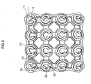
- Fig. 2 is a plan view of an example of the probe holder with the probe mounting parts 2 being arranged in a 4 x 4 matrix.
- the probe holder 1 is formed of a material such as silicone in a bowl-like shape to conform with the configuration of the head of the subject.
- the probe holder 1 is curved such that the curvature thereof decreases gradually from the central portion toward the peripheral ends thereof.
- a plurality of rectangular openings 12 are provided in order to facilitate fine adjustment of the probe holder 1 through bending in conformity with the size and configuration of the head of the subject.
- the slits 1a, 1b, 1c, 1d, etc. are provided at the four corners of the probe holder 1, there are provided the slits 1a, 1b, 1c, 1d, etc.
- the adjusting strap 9a is passed through the slits 1a, 1b for engagement, and the slits are large enough to allow passage of the adjusting strap 9a.
- the probe mounting parts 2 serve to fix optical fiber probes in position.
- irradiation optical fiber probes and light collection optical fiber probes are alternately arranged.
- a cutout 2b is provided in a part of the circumference of each probe mounting part 2. That is, each probe mounting part 2 has a C-shaped sectional configuration. Since it is possible to observe the forward end of the mounted probe through the cutout 2b, it is possible to perform setting while checking the way the probe is mounted in relation to the head surface. Further, it is possible to insert a hair avoiding jig, an air blower, or the like into the cutout 2b, making it possible to avoid hair.
- each probe mounting part 2 In the inner peripheral surface of each probe mounting part 2, there is provided a recess 2a for fixing the optical fiber probe in position, and the optical fiber probe is provided with a protrusion adapted to be fitted into the recess 2a.
- the optical fiber probe is fixed to the probe mounting part 2 without looseness, keeping a fixed distance between the optical fiber probe and the subject.
- grooves for locking the mounting device body 4 are provided in the outer peripheral surfaces of the probe mounting parts 2. By locking the mounting device body 4 to those grooves, the mounting device body 4 is fixed to the probe mounting parts 2.
- slits 11 are provided at fixed intervals in the outer periphery of the probe holder 1.
- straps or the like are passed through the mounting device body 4 and the slits 11 at the positions where the slits 11 and the mounting device body 4 overlap each other. It is also possible to pass the adjusting strap 9a through the slits 11.
- the intermediate portions of the adjusting straps 9a through 9c are engaged with the probe holders 1 by being inserted into the slits 1a .
- the probe holders 1 are made to extend in conformity with the configuration of the head, thereby enhancing the intimateness with which the probe holders 1 are held in contact with the head.
- the adjusting straps 9a through 9c may be passed through other holes of the probe holders 1 or wrapped around the probe mounting parts 2.
- Fig. 3 is a front view of the head of the subject to which the probe holders 1 and the probe holder mounting device 3 of Fig. 1 are mounted
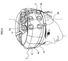
- Fig. 4 is a perspective view of the subject of Fig. 3
- Fig. 5 is a perspective view of the subject of Fig. 3 as seen from an angle different from that of Fig. 4 .
- the arrangement of the adjusting straps 9a, 9b is determined as appropriate according to the type of probe holders 1 used, the size of the head of the subject, etc.
- the connection of the adjusting straps 9a, 9b will be described specifically.
- the start end portion of the adjusting strap 9a is fixed to the buckle 8b.
- the adjusting strap 9a fixed to the buckle 8b is passed through the slit 1c on the head-front side of one probe holder 1. Further, the adjusting strap 9a thus passed is passed through the slit 1a on the head-front side of the other probe holder 1. Further, the terminal end portion of the adjusting strap 9a engaged with the two probe holders 1 is fixed with the buckle 8e. Also, the start end portion of the adjusting strap 9b is fixed to the buckle 8f. The adjusting strap 9b fixed to the buckle 8f is passed through the slit 1b on the head-rear side of one probe holder 1.
- the adjusting strap 9b thus passed is passed through the slit 1d on the head-rear side of the other probe holder 1. Then, the terminal end portion of the adjusting strap 9b engaged with the two probe holders 1 is fixed to the buckle 8a. In this way, the adjusting straps 9a, 9b are tightened.
- the adjusting strap 9c is not used, and thus is removed.
- the core 7 has a center line 10 indicating the horizontal center of the probe holder mounting device 3. In this way, there are provided not only the mark lines 4b for the positioning of the probe holders 1 with respect to the probe holder mounting device 3, but also a line for the positioning of the probe holder mounting device 3 with respect to the subject, whereby it is possible to arrange the probe holders 1 at the measurement positions more smoothly.
- Fig. 6 is a plan view of the probe holder mounting device 3 of Fig. 1 as combined with the probe holder 1 of a different type.
- the probe mounting parts 2 are arranged in a 5 x 3 matrix, with the probe holder 1 being arranged at the center of the probe holder mounting device 3.
- Fig. 1 shows an arrangement of the probe holders 1 for performing measurement on the right and left temporal portions
- Fig. 6 shows an arrangement of the probe holder 1 for performing measurement on the frontal portion.
- the mounting device body 4 has a front mounting portion to be held on the frontal portion of the subject, a left-hand mounting portion to be held on the left temporal portion, and a right-hand mounting portion to be held on the right temporal portion.
- the probe holder mounting device 3 is applicable to all types of probe holders 1 and applicable to all measurement positions.
- the probe holder mounting device 3 which uses the band-like mounting device body 4 to be wrapped around the subject, there is less of an intense tightening feel for the subject as compared with the case of a constrictive cap-type mounting device, of annular rubber member or the like. Further, the top portion of the head is not covered with the mounting device body 4 but exposed, so the mounting position can be easily checked, and the mounting on the subject is facilitated. Further, through connecting position adjustment of the adjusting straps 9a through 9c, it is possible to effect fine adjustment on the position of the probe holder 1.
- the mounting device body 4 is provided with the core 7 having no expandability, and, when wrapping the mounting device body 4 around the head of the subject, the core 7 is applied to the forehead of the subject so as to be in conformity with the configuration thereof, so it is possible to fix the mounting device body 4 firmly to the subject without causing the subject to experience an intense tightening feel.
- the mounting device body 4 is provided with the mark lines 4b, it is possible to provide the insertion holes 4a symmetrically, making it possible to arrange the probe holders 1 easily at the proper positions.
- a nonwoven fabric of polyester fibers, polyolefin fibers or the like is suitable.
- the belt 5b with a scale in correspondence with the size of the head of the subject, using the scale as a guide in adjusting the tightening degree.
- the color of the mounting device body 4 at least the portions where the probe holders 1 are mounted are preferably formed in black, which helps to achieve an improvement in terms of shielding property.
- the color of the portions of the mounting device body 4 where the probe holders 1 are mounted different from the color of at least one of the belts 5a, 5b, the adjusting straps 9a through 9c, and the extension parts 4c, 4d, it is possible to improve the workability of the mounting operation to the head of the subject.
Landscapes
- Health & Medical Sciences (AREA)
- Life Sciences & Earth Sciences (AREA)
- Physics & Mathematics (AREA)
- Heart & Thoracic Surgery (AREA)
- Molecular Biology (AREA)
- Veterinary Medicine (AREA)
- Biophysics (AREA)
- Pathology (AREA)
- Engineering & Computer Science (AREA)
- Biomedical Technology (AREA)
- Public Health (AREA)
- Medical Informatics (AREA)
- General Health & Medical Sciences (AREA)
- Surgery (AREA)
- Animal Behavior & Ethology (AREA)
- Optics & Photonics (AREA)
- Neurology (AREA)
- Spectroscopy & Molecular Physics (AREA)
- Measurement Of The Respiration, Hearing Ability, Form, And Blood Characteristics Of Living Organisms (AREA)
- Measuring Pulse, Heart Rate, Blood Pressure Or Blood Flow (AREA)
Abstract
A probe holder mounting device for a biological photometric device includes: a probe holder having a plurality of probe mounting parts to which optical fiber probes are mounted; a band-like mounting device body having a plurality of insertion holes into which the probe mounting parts are to be inserted to fix the probe holder in position by means of the insertion holes; belts whose one ends are respectively connected to both longitudinal ends of the mounting device body and whose other ends are engaged with each other; and an adjusting belt connected to the mounting device body at a position where the probe holder is fixed in position in a lateral direction of the mounting device body.
Description
- The present invention relates to a probe holder mounting device for a biological photometric device, which is used when mounting a probe holder of a biological photometric device to a subject.
- In a conventional probe device, a plurality of probes are arranged on a shell portion in a lattice-like fashion. A belt is connected to the shell portion via a strap, and, by wrapping the belt around the chin, the shell portion is mounted to the head. The shell portion is formed of a soft rubber such as silicone rubber so that the shell portion may extend in conformity with the head (see, for example, Patent Document 1).
- Patent Document 1:
JP 2001-286449 A - In the above-described conventional method of mounting the shell portion, the belt is wrapped around the chin, so the subject is subjected to feeling of tightness. Further, fine adjustment of the probe positions is rather difficult to perform, resulting in rather poor reproducibility of the mounting position.
- The present invention has been made with a view toward solving the above problems. It is an object of the present invention to provide a probe holder mounting device for a biological photometric device which allows easy mounting to a subject without involving excessive tightness and which allows fine adjustment of probe holder positions.
- A probe holder mounting device for a biological photometric device according to the present invention includes: a probe holder having a probe mounting part for fixing in position an optical fiber probe; a mounting device body into which the probe mounting part is inserted to fix the probe holder in position; a belt connected to both longitudinal ends of the mounting device body for tightening around the head of a subject; and an adjusting belt connected to a lateral end of the mounting device body and to the probe holder.
-
- [
Fig. 1 ] A plan view of a probe holder mounting device for a biological photometric device according to Embodiment 1 of the present invention. - [
Fig. 2 ] A plan view of an example of a probe holder. - [
Fig. 3 ] A front view of a head of a subj ect to which the probe holders and the probe holder mounting device ofFig. 1 are mounted. - [
Fig. 4 ] A perspective view of the subject ofFig. 3 . - [
Fig. 5 ] A perspective view of the subject ofFig. 3 as seen from an angle different from that ofFig. 4 . - [
Fig. 6 ] A plan view of the probe holder mounting device ofFig. 1 as combined with a different type of probe holder. - In the following, a preferred embodiment of the present invention will be described with reference to the drawings.
-
Fig. 1 is a plan view of a probe holder mounting device for a biological photometric device according to Embodiment 1 of the present invention with two probe holders 1 mounted thereto. In the figure, each probe holder 1 is equipped with a plurality of probe mounting parts (sockets) 2 to which optical fiber probes are to be mounted. Theprobe mounting parts 2 are arranged in a matrix-like fashion. The base portions of the probe holders 1 are formed of a flexible material such as silicone rubber. - The probe holders 1 are mounted to the head of the subject by using a probe
holder mounting device 3. The probeholder mounting device 3 has a band-likemounting device body 4,belts mounting device body 4 and tightening around the head of the subject, amain buckle 6 provided on the onebelt 5a serves as a main fastening member, a strap-like core 7 fixed in position so as to extend in the longitudinal direction of themounting device body 4, a plurality of adjustingstrap buckles 8a through 8f mounted at intervals to themounting device body 4, and a plurality of adjustingstraps 9a through 9c connected to themounting device body 4 either through the intermediation of the adjustingstrap buckles 8a through 8f or directly. - The
mounting device body 4 is formed of an expandable cloth and is wrapped around the subject when mounting the probe holders 1 to the subject. Themounting device body 4 is provided with a plurality ofinsertion holes 4a for inserting theprobe mounting parts 2 of the probe holders 1. Theinsertion holes 4a are provided by using a pair of scissors or the like in conformity with the positions of theprobe mounting parts 2 of the probe holders 1 used. - As shown in
Fig. 1 , sixinsertion holes 4a are respectively provided on the right-hand and left-hand sides of themounting device body 4. That is, each probe holder 1 has the nineprobe mounting parts 2, of which six are inserted into theinsertion holes 4a and three are not inserted into theinsertion holes 4a. In this way, it is not always necessary for all theprobe mounting parts 2 to be inserted into theinsertion holes 4a. - The
mounting device body 4 is symmetrically provided with lattice-like mark lines 4b serving as positional guides in providing theinsertion holes 4a. When providing theinsertion holes 4a, by referring to themark lines 4b, it is possible to provide theinsertion holes 4a symmetrically, with the result that the probe holders 1 can be arranged symmetrically. Band-like extension parts 4c, 4d are connected to the right and left ends of themounting device body 4. - When mounting the probe holders 1 to the head of the subject, the
mounting device body 4 is wrapped around the head so as to fit thecore 7 in conformity with the forehead, and the end portion of thebelt 5b is connected to themain buckle 6. Thebelts main buckle 6 connect the end portions of themounting device body 4, and function as a connection adjusting means for adjusting the tightening force in conformity with the size of the head. The tightening force is adjusted to a minimum force needed to fix themounting device body 4 to the head. - The
core 7 is formed of a material having no expandability (a material whose expandability is sufficiently lower than that of the mounting device body 4) so that thecore 7 may not impart to the head tightening stronger than the tightening force adjusted by thebelts main buckle 6. Variations in the outer peripheral length of the head of the subject are coped with by thebelt 5b and themain buckle 6. Further, themounting device body 4 is equipped with the extension parts 4c., 4d for mounting the probeholder mounting device 3 to the head. By connecting theextension parts 4c, 4d at the back of the head, the probeholder mounting device 3 can be mounted to the head. In this way, by effecting tightening using theextension parts 4c, 4d, it is also possible to mount the probeholder mounting device 3 to the head without using thebelts main buckle 6. - The adjusting
straps 9a through 9c are thin belt-like straps havingawidth, for example, of approximately 10 mm, and, whenmounting the probe holders 1 to the subject, they are stretched between two different points on themounting device body 4, and are engaged with the probe holders 1. For example, as shown inFig. 1 , one end portion of the adjustingstraps buckles straps slits straps buckles straps 9a through 9c are connected to a lateral end of themounting device body 4 and to the probe holders. -
Fig. 2 is a plan view of an example of the probe holder with theprobe mounting parts 2 being arranged in a 4 x 4 matrix. The probe holder 1 is formed of a material such as silicone in a bowl-like shape to conform with the configuration of the head of the subject. The probe holder 1 is curved such that the curvature thereof decreases gradually from the central portion toward the peripheral ends thereof. A plurality of rectangular openings 12 are provided in order to facilitate fine adjustment of the probe holder 1 through bending in conformity with the size and configuration of the head of the subject. - At the four corners of the probe holder 1, there are provided the
slits strap 9a is passed through theslits strap 9a. - The
probe mounting parts 2 serve to fix optical fiber probes in position. In theprobe mounting parts 2, irradiation optical fiber probes and light collection optical fiber probes are alternately arranged. Acutout 2b is provided in a part of the circumference of eachprobe mounting part 2. That is, eachprobe mounting part 2 has a C-shaped sectional configuration. Since it is possible to observe the forward end of the mounted probe through thecutout 2b, it is possible to perform setting while checking the way the probe is mounted in relation to the head surface. Further, it is possible to insert a hair avoiding jig, an air blower, or the like into thecutout 2b, making it possible to avoid hair. In the inner peripheral surface of eachprobe mounting part 2, there is provided arecess 2a for fixing the optical fiber probe in position, and the optical fiber probe is provided with a protrusion adapted to be fitted into therecess 2a. Thus, the optical fiber probe is fixed to theprobe mounting part 2 without looseness, keeping a fixed distance between the optical fiber probe and the subject. Further, grooves for locking the mountingdevice body 4 are provided in the outer peripheral surfaces of theprobe mounting parts 2. By locking the mountingdevice body 4 to those grooves, the mountingdevice body 4 is fixed to theprobe mounting parts 2. - Further, slits 11 are provided at fixed intervals in the outer periphery of the probe holder 1. When fixing the probe holder 1 and the mounting
device body 4 to each other through integration, straps or the like are passed through the mountingdevice body 4 and theslits 11 at the positions where theslits 11 and the mountingdevice body 4 overlap each other. It is also possible to pass the adjustingstrap 9a through theslits 11. - The intermediate portions of the adjusting straps 9a through 9c are engaged with the probe holders 1 by being inserted into the
slits 1a . Thus, by adjusting the positions where the adjusting straps 9a through 9c are connected with the adjusting strap buckles 8a through 8f, it is possible to effect fine adjustment of the distance between the probe holders 1 and the distances between the adjusting strap buckles 8a through 8f and the probe holders 1. Further, the probe holders 1 are made to extend in conformity with the configuration of the head, thereby enhancing the intimateness with which the probe holders 1 are held in contact with the head. The adjusting straps 9a through 9c may be passed through other holes of the probe holders 1 or wrapped around theprobe mounting parts 2. -
Fig. 3 is a front view of the head of the subject to which the probe holders 1 and the probeholder mounting device 3 ofFig. 1 are mounted,Fig. 4 is a perspective view of the subject ofFig. 3 , andFig. 5 is a perspective view of the subject ofFig. 3 as seen from an angle different from that ofFig. 4 . There are no particular limitations regarding the arrangement of the adjustingstraps - The connection of the adjusting
straps strap 9a is fixed to thebuckle 8b. The adjustingstrap 9a fixed to thebuckle 8b is passed through theslit 1c on the head-front side of one probe holder 1. Further, the adjustingstrap 9a thus passed is passed through theslit 1a on the head-front side of the other probe holder 1. Further, the terminal end portion of the adjustingstrap 9a engaged with the two probe holders 1 is fixed with thebuckle 8e. Also, the start end portion of the adjustingstrap 9b is fixed to thebuckle 8f. The adjustingstrap 9b fixed to thebuckle 8f is passed through theslit 1b on the head-rear side of one probe holder 1. Further, the adjustingstrap 9b thus passed is passed through theslit 1d on the head-rear side of the other probe holder 1. Then, the terminal end portion of the adjustingstrap 9b engaged with the two probe holders 1 is fixed to thebuckle 8a. In this way, the adjustingstraps - In this mounting example, the adjusting
strap 9c is not used, and thus is removed. Further, thecore 7 has acenter line 10 indicating the horizontal center of the probeholder mounting device 3. In this way, there are provided not only themark lines 4b for the positioning of the probe holders 1 with respect to the probeholder mounting device 3, but also a line for the positioning of the probeholder mounting device 3 with respect to the subject, whereby it is possible to arrange the probe holders 1 at the measurement positions more smoothly. -
Fig. 6 is a plan view of the probeholder mounting device 3 ofFig. 1 as combined with the probe holder 1 of a different type. In this example, theprobe mounting parts 2 are arranged in a 5 x 3 matrix, with the probe holder 1 being arranged at the center of the probeholder mounting device 3. That is,Fig. 1 shows an arrangement of the probe holders 1 for performing measurement on the right and left temporal portions, andFig. 6 shows an arrangement of the probe holder 1 for performing measurement on the frontal portion. That is, the mountingdevice body 4 has a front mounting portion to be held on the frontal portion of the subject, a left-hand mounting portion to be held on the left temporal portion, and a right-hand mounting portion to be held on the right temporal portion. Thus, the probeholder mounting device 3 is applicable to all types of probe holders 1 and applicable to all measurement positions. - In the probe
holder mounting device 3, which uses the band-likemounting device body 4 to be wrapped around the subject, there is less of an intense tightening feel for the subject as compared with the case of a constrictive cap-type mounting device, of annular rubber member or the like. Further, the top portion of the head is not covered with the mountingdevice body 4 but exposed, so the mounting position can be easily checked, and the mounting on the subject is facilitated. Further, through connecting position adjustment of the adjusting straps 9a through 9c, it is possible to effect fine adjustment on the position of the probe holder 1. - Further, the mounting
device body 4 is provided with thecore 7 having no expandability, and, when wrapping the mountingdevice body 4 around the head of the subject, thecore 7 is applied to the forehead of the subject so as to be in conformity with the configuration thereof, so it is possible to fix the mountingdevice body 4 firmly to the subject without causing the subject to experience an intense tightening feel. - Further, since the mounting
device body 4 is provided with themark lines 4b, it is possible to provide the insertion holes 4a symmetrically, making it possible to arrange the probe holders 1 easily at the proper positions. - As the expandable cloth forming the mounting
device body 4, a nonwoven fabric of polyester fibers, polyolefin fibers or the like is suitable. - Further, it is also possible to provide the
belt 5b with a scale in correspondence with the size of the head of the subject, using the scale as a guide in adjusting the tightening degree.
Further, while there are no particular limitations regarding the color of the mountingdevice body 4, at least the portions where the probe holders 1 are mounted are preferably formed in black, which helps to achieve an improvement in terms of shielding property.
Further, by making the color of the portions of the mountingdevice body 4 where the probe holders 1 are mounted different from the color of at least one of thebelts straps 9a through 9c, and theextension parts 4c, 4d, it is possible to improve the workability of the mounting operation to the head of the subject.
Further, it is also possible to provide a scale on the surface of thecore 7. When mounting the mountingdevice body 4 and the probe holders 1, a scale in correspondence with the positions of the eyebrows and the glabella is recorded, whereby it is possible to repeatedly mount the mountingdevice body 4 and the probe holders 1 while checking the positions of the eyebrows and the glabella in accordance with the previously recorded scale. Thus, it is possible to achieve an improvement in terms of the reproducibility of the mounting of the mountingdevice body 4 and the probe holders 1 to the head.
Claims (19)
- A probe holder mounting device for a biological photometric device, comprising:a probe holder having a plurality of probe mounting parts to which optical fiber probes are mounted;a band-like mounting device body having a plurality of insertion holes into which the probe mounting parts are to be inserted to fix the probe holder in position by means of the insertion holes;belts whose one ends are respectively connected to both longitudinal ends of the mounting device body and whose other ends are engaged with each other; andan adjusting belt connected to the mounting device body at a position where the probe holder is fixed in position in a lateral direction of the mounting device body.
- The probe holder mounting device for a biological photometric device according to Claim 1, wherein the adjusting belt comprises a plurality of adjusting belts provided on the mounting device body.
- The probe holder mounting device for a biological photometric device according to Claim 2, further comprising a plurality of adjusting belt fastening members which are mounted at intervals to a lateral end of the mounting device body and to which the adjusting belts are connected.
- The probe holder mounting device for a biological photometric device according to Claim 1, further comprising a core which is provided on the mounting device body, which is formed of a material of lower expandability than the mounting device body, and which is held snugly on the forehead of a subject when wrapping the mounting device body around the head of the subject.
- The probe holder mounting device for a biological photometric device according to Claim 4, wherein the core is provided with a center line indicating a horizontal center thereof.
- The probe holder mounting device for a biological photometric device according to Claim 1, wherein the mounting device body is symmetrically provided with mark lines serving as positional guides in providing the insertion holes.
- The probe holder mounting device for a biological photometric device according to Claim 6, wherein the mark lines are provided in a lattice-like fashion.
- The probe holder mounting device for a biological photometric device according to Claim 1, wherein the mounting device body has a front mounting portion to be held on a frontal portion of a subject, a left-hand mounting portion to be held on a left temporal portion of the subject, and a right-hand mounting portion to be held on a right temporal portion of the subject.
- The probe holder mounting device for a biological photometric device according to Claim 1, wherein the mounting device body is provided with band-like extension parts connected to left and right end portions thereof.
- The probe holder mounting device for a biological photometric device according to Claim 2, wherein the probe holder is provided at an end thereof with a slit through which the adjusting belt is to be passed.
- The probe holder mounting device for a biological photometric device according to Claim 1, further comprising a second belt connected to both ends of the mounting device body.
- The probe holder mounting device for a biological photometric device according to Claim 1, wherein the probe holder comprises a plurality of probe holders fixed to the mounting device body.
- The probe holder mounting device for a biological photometric device according to Claim 1, wherein the plurality of probe mounting parts are arranged in a matrix-like fashion.
- The probe holder mounting device for a biological photometric device according to Claim 2, wherein the adjusting belt is directly connected to the mounting device body.
- The probe holder mounting device for a biological photometric device according to Claim 1, wherein the mounting device body is formed of an expandable cloth.
- The probe holder mounting device for a biological photometric device according to Claim 1, wherein the adjusting belt is connected to a lateral end of the mounting device body and to the probe holder.
- The probe holder mounting device for a biological photometric device according to Claim 1, wherein the probe holder is formed of silicone in a bowl-like configuration and is provided with a rectangular opening.
- The probe holder mounting device for a biological photometric device according to Claim 1, wherein the probe holder is curved such that the curvature thereof is gradually diminished from a central portion thereof toward a peripheral end thereof.
- A probe holder mounting device for a biological photometric device, comprising:a probe holder having a probe mounting part to which an optical fiber probe is mounted;a mounting device body into which the probe mounting part is inserted to fix the probe holder in position;a belt connected to both longitudinal ends of the mounting device body for tightening on the head of a subject; andan adjusting strap connected to a lateral end of the mounting device body and to the probe holder.
Applications Claiming Priority (2)
| Application Number | Priority Date | Filing Date | Title |
|---|---|---|---|
| JP2005247598 | 2005-08-29 | ||
| PCT/JP2006/316861 WO2007026644A1 (en) | 2005-08-29 | 2006-08-28 | Probe holder mounting device of living body optical measuring device |
Publications (1)
| Publication Number | Publication Date |
|---|---|
| EP1922997A1 true EP1922997A1 (en) | 2008-05-21 |
Family
ID=37808734
Family Applications (1)
| Application Number | Title | Priority Date | Filing Date |
|---|---|---|---|
| EP06783090A Withdrawn EP1922997A1 (en) | 2005-08-29 | 2006-08-28 | Probe holder mounting device of living body optical measuring device |
Country Status (5)
| Country | Link |
|---|---|
| US (1) | US8423111B2 (en) |
| EP (1) | EP1922997A1 (en) |
| JP (1) | JP4937916B2 (en) |
| CN (1) | CN101222876B (en) |
| WO (1) | WO2007026644A1 (en) |
Cited By (1)
| Publication number | Priority date | Publication date | Assignee | Title |
|---|---|---|---|---|
| EP2190349B1 (en) * | 2007-09-28 | 2015-11-11 | Raumedic Ag | Sensor system for measuring, transferring, processing and displaying a brain parameter |
Families Citing this family (11)
| Publication number | Priority date | Publication date | Assignee | Title |
|---|---|---|---|---|
| US10307088B2 (en) | 2007-04-11 | 2019-06-04 | The Board Of Regents Of The University Of Texas | Systems and methods for measuring oxygenation |
| US10226206B2 (en) | 2007-04-11 | 2019-03-12 | The Board Of Regents Of The University Of Texas System | Systems and methods for measuring neonatal cerebral oxygenation |
| US10052045B2 (en) | 2012-12-21 | 2018-08-21 | Colgate-Palmolive Company | Method for testing oral malodor |
| US20140276014A1 (en) * | 2013-03-13 | 2014-09-18 | Cephalogics, LLC | Supports for optical sensors and related apparatus and methods |
| CN106999113A (en) | 2014-07-08 | 2017-08-01 | 德克萨斯大学系统董事会 | Systems and methods for measuring fetal brain oxygenation |
| JP2016067482A (en) * | 2014-09-29 | 2016-05-09 | 株式会社日立メディコ | Optical measurement probe fixture and biological optical measurement apparatus with the same |
| US10375901B2 (en) | 2014-12-09 | 2019-08-13 | Mtd Products Inc | Blower/vacuum |
| WO2016110969A1 (en) * | 2015-01-07 | 2016-07-14 | 株式会社日立製作所 | Biophoton measurement device |
| WO2016149107A1 (en) | 2015-03-14 | 2016-09-22 | Board Of Regents | Systems and methods for measuring neonatal cerebral oxygenation |
| JP2017055816A (en) * | 2015-09-14 | 2017-03-23 | 株式会社島津製作所 | Brain function measurement apparatus and probe holder for brain function measurement apparatus |
| CN107898431A (en) * | 2017-09-30 | 2018-04-13 | 武汉资联虹康科技股份有限公司 | A kind of laser probe mounting cap |
Family Cites Families (13)
| Publication number | Priority date | Publication date | Assignee | Title |
|---|---|---|---|---|
| CN2148534Y (en) * | 1991-12-03 | 1993-12-08 | 王耀君 | Electrodo cap for electroencephalogram |
| JPH05317295A (en) * | 1992-05-26 | 1993-12-03 | Omron Corp | Probe for measuring oxygen of living body tissue |
| US5680857A (en) * | 1992-08-28 | 1997-10-28 | Spacelabs Medical, Inc. | Alignment guide system for transmissive pulse oximetry sensors |
| JPH06319723A (en) * | 1993-05-13 | 1994-11-22 | Omron Corp | Exercise monitor |
| JPH0928696A (en) | 1995-07-21 | 1997-02-04 | Hitachi Ltd | Optical measuring device and optical measuring method |
| JPH0928698A (en) | 1995-07-21 | 1997-02-04 | Hitachi Ltd | Optical measurement device |
| JP2965526B2 (en) | 1997-01-13 | 1999-10-18 | 協和電機化学株式会社 | Method for producing sheet-like plastic article having projections on its surface |
| JP4484373B2 (en) * | 1999-03-29 | 2010-06-16 | 株式会社日立メディコ | Biological light measurement device |
| JP4090699B2 (en) * | 2001-04-02 | 2008-05-28 | 株式会社日立製作所 | Biological light measurement device |
| JP4283467B2 (en) * | 2001-11-12 | 2009-06-24 | 株式会社日立製作所 | Biological measurement probe and biological optical measurement apparatus using the same |
| JP2003310622A (en) * | 2002-04-18 | 2003-11-05 | Communication Research Laboratory | Headgear for brain light measurement apparatus |
| JP4699213B2 (en) * | 2003-12-02 | 2011-06-08 | 株式会社日立メディコ | Probe device for biological light measurement device |
| JP2006149611A (en) | 2004-11-29 | 2006-06-15 | Shiseido Co Ltd | Implement for attaching probe of brain-activity measuring apparatus |
-
2006
- 2006-08-28 WO PCT/JP2006/316861 patent/WO2007026644A1/en not_active Ceased
- 2006-08-28 EP EP06783090A patent/EP1922997A1/en not_active Withdrawn
- 2006-08-28 JP JP2007533223A patent/JP4937916B2/en active Active
- 2006-08-28 CN CN2006800258591A patent/CN101222876B/en not_active Expired - Fee Related
- 2006-08-28 US US12/065,095 patent/US8423111B2/en not_active Expired - Fee Related
Non-Patent Citations (1)
| Title |
|---|
| See references of WO2007026644A1 * |
Cited By (1)
| Publication number | Priority date | Publication date | Assignee | Title |
|---|---|---|---|---|
| EP2190349B1 (en) * | 2007-09-28 | 2015-11-11 | Raumedic Ag | Sensor system for measuring, transferring, processing and displaying a brain parameter |
Also Published As
| Publication number | Publication date |
|---|---|
| WO2007026644A1 (en) | 2007-03-08 |
| US8423111B2 (en) | 2013-04-16 |
| CN101222876A (en) | 2008-07-16 |
| CN101222876B (en) | 2010-05-19 |
| JPWO2007026644A1 (en) | 2009-03-05 |
| US20090262342A1 (en) | 2009-10-22 |
| JP4937916B2 (en) | 2012-05-23 |
Similar Documents
| Publication | Publication Date | Title |
|---|---|---|
| US8423111B2 (en) | Probe holder mounting device for biological photometric device | |
| US7139600B2 (en) | Biophotometer | |
| EP1574166B1 (en) | Measuring probe and living body optical measuring device | |
| EP3297530B1 (en) | Headwear for electroencephalography | |
| JP4484373B2 (en) | Biological light measurement device | |
| EP1779775A1 (en) | Brain function detector | |
| US20210121066A1 (en) | Wearable open and adjustable mri head coil | |
| CN103961090A (en) | A device that can be mounted on the head and has electrodes for electroencephalography | |
| JP2009195348A (en) | Biological optical measurement probe and biological optical measurement instrument therewith | |
| KR20200121127A (en) | Device to wear on head to measure EEG | |
| JP2002355246A (en) | Accessory for biological light measurement and biological light meter | |
| EP3320848B1 (en) | Positioning apparatus for head and neck assessment or intervention | |
| JP4408878B2 (en) | Biological light measurement device | |
| CN214070135U (en) | Bone conduction earphone with headband height adjusting support | |
| HU206458B (en) | Holding device for endotracheal tube | |
| WO2022050457A1 (en) | Head-adaptive near-infrared spectrometer | |
| WO2019084550A1 (en) | Easily applied neurological monitoring template | |
| JP2011083433A (en) | Magnetoencephalograph | |
| EP4590196A1 (en) | Cap device for use in taking measurement data from a head of a person | |
| JP2016067482A (en) | Optical measurement probe fixture and biological optical measurement apparatus with the same | |
| CN221555635U (en) | Improved electrode fixing head sleeve for electroencephalogram | |
| JP2026016911A (en) | Probe mounting holder for optical brain function measurement equipment | |
| EP0436318A1 (en) | Sensor applicator | |
| KR20260020009A (en) | Transcranial Electric Stimulation Apparatus | |
| JP2503117Y2 (en) | Swimming goggles |
Legal Events
| Date | Code | Title | Description |
|---|---|---|---|
| PUAI | Public reference made under article 153(3) epc to a published international application that has entered the european phase |
Free format text: ORIGINAL CODE: 0009012 |
|
| 17P | Request for examination filed |
Effective date: 20080326 |
|
| AK | Designated contracting states |
Kind code of ref document: A1 Designated state(s): DE FR GB IT NL |
|
| DAX | Request for extension of the european patent (deleted) | ||
| RBV | Designated contracting states (corrected) |
Designated state(s): DE FR GB IT NL |
|
| STAA | Information on the status of an ep patent application or granted ep patent |
Free format text: STATUS: THE APPLICATION HAS BEEN WITHDRAWN |
|
| 18W | Application withdrawn |
Effective date: 20100805 |