EP1922700B1 - 2d/3d combined rendering - Google Patents
2d/3d combined rendering Download PDFInfo
- Publication number
- EP1922700B1 EP1922700B1 EP06814359.3A EP06814359A EP1922700B1 EP 1922700 B1 EP1922700 B1 EP 1922700B1 EP 06814359 A EP06814359 A EP 06814359A EP 1922700 B1 EP1922700 B1 EP 1922700B1
- Authority
- EP
- European Patent Office
- Prior art keywords
- shape
- effects
- factory
- ground plane
- text
- Prior art date
- Legal status (The legal status is an assumption and is not a legal conclusion. Google has not performed a legal analysis and makes no representation as to the accuracy of the status listed.)
- Active
Links
Images


Classifications
-
- G—PHYSICS
- G06—COMPUTING OR CALCULATING; COUNTING
- G06T—IMAGE DATA PROCESSING OR GENERATION, IN GENERAL
- G06T15/00—Three-dimensional [3D] image rendering
- G06T15/10—Geometric effects
-
- G—PHYSICS
- G06—COMPUTING OR CALCULATING; COUNTING
- G06T—IMAGE DATA PROCESSING OR GENERATION, IN GENERAL
- G06T15/00—Three-dimensional [3D] image rendering
- G06T15/50—Lighting effects
-
- G—PHYSICS
- G06—COMPUTING OR CALCULATING; COUNTING
- G06T—IMAGE DATA PROCESSING OR GENERATION, IN GENERAL
- G06T15/00—Three-dimensional [3D] image rendering
-
- G—PHYSICS
- G06—COMPUTING OR CALCULATING; COUNTING
- G06T—IMAGE DATA PROCESSING OR GENERATION, IN GENERAL
- G06T17/00—Three-dimensional [3D] modelling for computer graphics
Definitions
- Document WO 00/63848 A1 relates to the animation of three-dimensional characters along a path.
- a character is represented in a character generator as a set of polygons.
- the character may be manipulated using three-dimensional animation techniques.
- a code for a character may be used to access a set of curves defining the outline of the character. This set of curves is transformed into a set of polygons.
- the set of polygons may be rendered as a three-dimensional object.
- the set of polygons may be created by converting the curves into sets of connected line segments and then tessellating the polygon defined by the line segments.
- Animation properties are represented using a normalized scale along a path or over time.
- Animation may be provided in a manner that is independent of the spatial and temporal resolution of the video to which it is applied. Such animation may be applied to characters defined by a set of polygons. Various three-dimensional spatial transformations, lighting effects and other colorizations may be provided.
- a user interface for editing a character string may provide two alternate displays. A first display allows a user to input and view any desired portion of the character string for the purpose of editing. A second display allows a user to view how the character string appears at a selected point in time during a titling effect for the purpose of animation. In both displays, the text is displayed in a three-dimensional form. This interface may be combined with a timeline editing interface for editing an associated video program, or other user interface, to permit layering of titling effects and adjustment of animation properties, positioning and timing.
- a system that combines 2D and 3D modeling in rendering shapes includes: a 3D modeling factory to generate a 3D model of selected shape parameters or features; a front face factory to generate 2D text and text effects, and some 2D shape effects (e.g., fill effects); a ground plane factory to generate effects that are rendered on a ground plane of a shape; and a rasterizer/compositing engine to combine 2D and 3D effects generated by the front face factory, ground plan factory, and the 3D modeling factory.
- a 3D modeling factory to generate a 3D model of selected shape parameters or features
- a front face factory to generate 2D text and text effects, and some 2D shape effects (e.g., fill effects)
- a ground plane factory to generate effects that are rendered on a ground plane of a shape
- a rasterizer/compositing engine to combine 2D and 3D effects generated by the front face factory, ground plan factory, and the 3D modeling factory.
- the front face factory disassembles the shape into the following parts: text included in the shape (if any); the 2D surface of the front face (i.e., the surface effects of the front face of the shape); the 3D effects (if any) applied to the text; any ground plane effects (e.g., shadow, glow, reflection effects that are rendered into a ground plane of the shape); and the geometry of the shape (e.g., circle, rectangle, arrow, etc.).
- text included in the shape if any
- the 2D surface of the front face i.e., the surface effects of the front face of the shape
- the 3D effects if any applied to the text
- any ground plane effects e.g., shadow, glow, reflection effects that are rendered into a ground plane of the shape
- the geometry of the shape e.g., circle, rectangle, arrow, etc.
- the front face factory renders any 2D text effects (e.g. shadow, glow, reflection); any 2D shape effects; any 2D surface effects (e.g., fill, gradient fill, image, etc.) and the 2D geometry of the shape; and creates a texture map using the rendered 2D text effects and 2D surface effects for the front surface of the shape.
- the ground plane factory generates a ground plane for the 2D shape effects (if any).
- the ground plane factory generates a ground plane for the 2D text effects.
- the 3D modeling factory generates a 3D model from the 2D shape geometry by defining extrusion and beveling properties of the shape. The 3D modeling factory then generates coordinates for mapping the texture onto the front face of the 3D model.
- the rasterizer/compositing engine then combines the resulting shape from the 3D modeling factory (i.e., with 3D geometry and 2D texture map) with the ground plane(s) from the ground plane factory.
- the rasterizer/compositing engine uses the texture coordinates to map the texture onto the 3D model.
- Embodiments may be implemented as a computer process, a computer system (including mobile handheld computing devices) or as an article of manufacture such as a computer program product.
- the computer program product may be a computer storage medium readable by a computer system and encoding a computer program of instructions for executing a computer process.
- the computer program product may also be a propagated signal on a carrier readable by a computing system and encoding a computer program of instructions for executing a computer process.
- the logical operations of the various embodiments are implemented (1) as a sequence of computer implemented steps running on a computing system and/or (2) as interconnected machine modules within the computing system.
- the implementation is a matter of choice dependent on the performance requirements of the computing system implementing the embodiment. Accordingly, the logical operations making up the embodiments described herein are referred to alternatively as operations, steps or modules.
- a problem with the aforementioned simulated 3D and the 3D modeling approaches is that they are incomplete with regard to typical business uses.
- users may have shapes with a 2D effect (e.g., a gradient) that they want to put into 3D perspective for effect, or a complex 3D model for which they want to use a picture texture map, a gradient effect, or a simple shadow.
- the simulated 3D approach and the 3D modeling approach separately only provide a portion of a solution for the above example scenario.
- Embodiments presented below allow the use of both 3D and 2D effects combined into one pipeline, which generates professional looking business graphics.
- the user need not have a detailed understanding of 3D modeling (which is likely among typical business users) in order to use embodiments of the system.
- FIGURE 1 illustrates an exemplary system 100 that combines 2D and 3D modeling in rendering shapes.
- system 100 includes a 2D/3D engine 102, and one or more application programs indicated as applications 104-1 through 104-N in FIGURE 1 .
- Applications 104-1 through 104-N use 2D/3D engine to provide 3D effects to 2D shapes and shape effects inputted by users of applications 104-1 through 104-N.
- 2D/3D engine 102 can also provide 3D effects to text associated with the shapes.
- 2D/3D engine 102 receives 2D shape input and generates a 3D model of some portions of the 2D shape so that the rendering output contains portions that are generated from 2D shapes and effects (and 2D text and effects, if any) and portions that are generated from the 3D model.
- This combined approach is unlike the aforementioned simulated 3D approach (which does not include a 3D model) and the purely 3D modeling approach.
- An example implementation of 2D/3D engine 102 is described below in conjunction with FIGURE 2 .
- each application that can generate 3D shapes may have an embedded 2D/3D engine as opposed to separate 2D/3D engine 102:
- FIGURE 2 illustrates exemplary components of 2D/3D engine 102 ( FIGURE 1 ) according to one embodiment.
- 2D/3D engine 102 includes a 3D modeling factory 202, a front face factory 204, a ground plane factory 206 and a rasterizer/compositing engine 208.
- 3D modeling factory 202 generates a 3D model of selected shape parameters or features.
- Front face factory 204 generates 2D text and text effects, and some 2D shape effects (e.g., fill effects).
- Ground plane factory 206 generates effects that are rendered on a ground plane of a shape.
- Rasterizer/compositing engine 208 combines 2D and 3D effects generated by front face factory 204, ground plane factory 206, and 3D modeling factory 202.
- front face factory 204 disassembles the shape into the following parts: text included in the shape (if any); the 2D surface of the front face (i.e., the surface effects of the front face of the shape); the 3D effects (if any) applied to the text; any ground plane effects (e.g., shadow, glow, reflection effects that are rendered into a ground plane of the shape); and the geometry of the shape (e.g., circle, rectangle, arrow, etc.).
- text included in the shape if any
- the 2D surface of the front face i.e., the surface effects of the front face of the shape
- the 3D effects if any applied to the text
- any ground plane effects e.g., shadow, glow, reflection effects that are rendered into a ground plane of the shape
- the geometry of the shape e.g., circle, rectangle, arrow, etc.
- front face factory 204 renders: any 2D text effects (e.g. shadow, glow, reflection); any 2D shape effects; any 2D surface effects (e.g., fill, gradient fill, image, etc.) and the 2D geometry of the shape; and creates a texture map using the rendered 2D text effects and 2D surface effects for the front surface of the shape.
- front face factory 204 generates the texture map so that the front surface of the shape retains its 2D surface effects (e.g., fill color) for all orientations of the shape under any simulated lighting conditions.
- this 2D surface effect preservation feature is desirable (even though it may appear less realistic) because the inputted 2D surface effect (e.g., color) is the effect that the users actually want as a result (as opposed to how the surface effect might appear when the shape with this surface effect is re-oriented).
- the inputted 2D surface effect e.g., color
- front face factory 204 dilates textures (e.g., containing the fill effect or image) by one pixel to make sure all parts of the front face of the 3D model are covered by the image fill.
- ground plane factory 206 generates a ground plane for the 2D shape effects (if any).
- ground plane factory 206 if the text has 3D effects applied, ground plane factory 206 generates a ground plane for the 2D text effects.
- Ground plane generator 206 takes 2D effects such as shadow, blur, and reflection and draws them into a background plane.
- 3D modeling factory e.g., as described below
- a ground plane is created and the 2D shape effects such as shadow, blur, and reflection are rendered on the ground plane.
- the ground plane would be rendered behind the shape.
- 3D modeling factory 202 generates a 3D model from the 2D shape geometry by defining extrusion and beveling properties of the shape.
- the 3D modeling factory then generates coordinates for mapping the texture onto the front face of the 3D model. For example, the 3D modeling factory will "wrap" the 2D surface effects (e.g., a picture or color) around the bevel.
- 3D modeling factory 202 generates contours of 3D shapes based on their underlying 2D geometry.
- An example of contours is illustrated in FIGURE 3 .
- the contours when a user enables the contours feature for a shape, the "outline" of the shape is made thicker.
- the color of the contour is user definable. For example, white contours can be used to set off dark shapes over a dark background.
- the contours are generated from the underlying 2D shape (shown as shape 302) and applied to the extrusion and beveling. The result is illustrated as shape 304.
- rasterizer/compositing engine 208 then combines the resulting shape from 3D modeling factory 202 (i.e., with 3D geometry and 2D texture map) with the ground plane(s) from ground plane factory 206.
- the rasterizer/compositing engine 208 uses the texture coordinates to map the texture onto the 3D model.
- a separate front face factory renders the 2D effects of the text.
- the 3D modeling factory generates a 3D model of the text by defining extrusion and beveling properties of the text and mapping the 2D text effects on the 3D model of the text.
- the ground plane factory creates a separate ground plane for the 3D text, and then 2D effects such as shadow, blur and reflection are rendered on this ground plane. This ground plane would sit on top of the shape so that the text effects will be viewable.
- An example of 3D text is illustrated in FIGURE 4 .
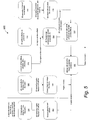
- FIGURE 5 is a flow diagram representing an operational flow 500 in generating a 3D graphic from a 2D shape input, according to an embodiment.
- Operational flow 500 may be performed in any suitable computing environment.
- operational flow 500 may be executed by a system such as 2D/3D engine 102 ( FIGURE 2 ). Therefore, the description of operational flow 500 may refer to at least one of the components of FIGURE 2 .
- any such reference to components of FIGURE 2 is for descriptive purposes only, and it is to be understood that the implementations of FIGURE 2 are a non-limiting environment for operational flow 500.
- a user using an application such as application 104-1 ( FIGURE 1 ) has created a shape that is to be rendered.
- a 2D rendering engine renders any 2D text effects that are to be applied to the text (e.g., as enabled by a user via the application).
- the 2D rendering engine is a standard 2D rendering engine and is part of a front face factory such as front face factory 204 ( FIGURE 2 ).
- a ground plane factory e.g., similar to ground plane factory 206 but directed to text instead of shapes creates a 3D ground plane for the text. This ground plane is separate from the ground plane of the shape.
- Blocks 502 and 504, in this example, are performed only if 3D effects are to be applied to the shape's text.
- 2D shape effects are applied to the shape.
- the aforementioned 2D rendering engine applies the 2D shape effects (e.g., shadow effect, glow effect, reflection effect) to the shape.
- a shape ground plane is created and the 2D shape effects are associated with the shape ground plane.
- a ground plane factory such as ground plane factory 206 creates the ground plane and associates the 2D shape effects (e.g., shadow effect, glow effect, reflection effect) to the shape ground plane.
- a block 510 is the same as block 502, but is performed in scenarios in which there are no 3D effects being applied to the shape's text.
- 2D surface effects are applied to the shape.
- the 2D rendering engine of the front face factory applies the surface effects (e.g., fill, gradient fill, image, etc.) to the shape.
- a texture map is created using the 2D text effects and 2D surface effects from blocks 510 and 512.
- the front face factory creates the texture map.
- a 2D geometry is obtained from the shape.
- a 3D modeling factory such as 3D modeling factory 202 ( FIGURE 2 ) obtains the 2D geometry from the shape.
- a 3D model is generated from the 2D geometry obtained at block 516.
- the aforementioned 3D modeling factory generates the 3D model by defining extrusion and bevel parameters for the shape.
- the texture map from block 514 is mapped onto the 3D model from block 518.
- the 3D modeling factory maps the texture map onto the 3D model so that the front face of the shape has the 2D text, text effects, and surface effects from blocks 510 and 512.
- the 3D modeling factory can also apply the texture map to 3D features such as the extrusion and bevel (e.g., "wrap" the fill around the bevels and extrusions).
- a bitmap is created from the 3D shape from block 520 combined with the ground plane from block 508.
- a rasterizer/compositing engine such as rasterizer/compositing engine 208 ( FIGURE 2 ) creates the bitmap.
- the rasterizer/compositing engine also uses the ground plane from block 504 to create the bitmap.
Landscapes
- Engineering & Computer Science (AREA)
- Physics & Mathematics (AREA)
- Computer Graphics (AREA)
- General Physics & Mathematics (AREA)
- Theoretical Computer Science (AREA)
- Geometry (AREA)
- Software Systems (AREA)
- Image Generation (AREA)
- Processing Or Creating Images (AREA)
Description
- There are a number of tools in existence today that let users create professional business graphics such as a presentation. An approach for adding polish to shapes and images is to apply 3D techniques. This is usually done in two ways: one is the use of simulated 3D effects on 2D bitmaps, which results in 3D looking shapes or images, without a real 3D model. The resulting simulated 3D graphics may not appear to be sufficiently 3D for some uses. The other approach is to use a full 3D model. Here the users build 3D models of the items to be displayed. This approach typically requires that the users be skilled in 3D modeling and in using the 3D modeling tool. This background information is not intended to identify problems that must be addressed by the claimed subject matter.
- Document
WO 00/63848 A1 - Kylander K. et Al.: "GIMP: The Official Handbook - The Gimp user's manual version 1.0.1 - chapters 8, 11, 20, 36"; 3 November 1999, provides a user indications on how to use the different tools supported by Gimp, as for example paint tools, text tools, or map filters. Maps such as "Bump Map" or "Map Object" can for instance be used to create 3D-effects of images. In addition, the user's manual provides information on the layers concept of Gimp and the way of using them.
- Adobe Creative Team: "Adobe Illustrator CS Classroom in a Book - Lesson 16: Using the 3D Effect", Adobe Press, page 419 to 444 and Adobe Creative Team: "Adobe Illustrator CS2 User Guide - Chapter 12: Reshaping objects", Adobe, pages 290 to 324 discuss using the 3D effect and reshaping objects in Adobe Illustrator CS.
- It is the object of the invention to easily generate 2D/3D combined rendering.
- This object is solved by the subject matter of the independent claims. Preferred embodiments are defined by the dependent claims.
- This summary is provided to introduce a selection of concepts in a simplified form that are further described below in the Detail Description Section. This summary is not intended to identify key features or essential features of the claimed subject matter, nor is it intended to be used as an aid in determining the scope of the claimed subject matter.
- According to aspects of various described embodiments, a system that combines 2D and 3D modeling in rendering shapes is provided. In one aspect, the system includes: a 3D modeling factory to generate a 3D model of selected shape parameters or features; a front face factory to generate 2D text and text effects, and some 2D shape effects (e.g., fill effects); a ground plane factory to generate effects that are rendered on a ground plane of a shape; and a rasterizer/compositing engine to combine 2D and 3D effects generated by the front face factory, ground plan factory, and the 3D modeling factory. When the system receives a shape with 3D effects, the front face factory disassembles the shape into the following parts: text included in the shape (if any); the 2D surface of the front face (i.e., the surface effects of the front face of the shape); the 3D effects (if any) applied to the text; any ground plane effects (e.g., shadow, glow, reflection effects that are rendered into a ground plane of the shape); and the geometry of the shape (e.g., circle, rectangle, arrow, etc.).
- The front face factory renders any 2D text effects (e.g. shadow, glow, reflection); any 2D shape effects; any 2D surface effects (e.g., fill, gradient fill, image, etc.) and the 2D geometry of the shape; and creates a texture map using the rendered 2D text effects and 2D surface effects for the front surface of the shape. The ground plane factory generates a ground plane for the 2D shape effects (if any). In addition, if the text has 3D effects applied, the ground plane factory generates a ground plane for the 2D text effects. The 3D modeling factory generates a 3D model from the 2D shape geometry by defining extrusion and beveling properties of the shape. The 3D modeling factory then generates coordinates for mapping the texture onto the front face of the 3D model. The rasterizer/compositing engine then combines the resulting shape from the 3D modeling factory (i.e., with 3D geometry and 2D texture map) with the ground plane(s) from the ground plane factory. The rasterizer/compositing engine uses the texture coordinates to map the texture onto the 3D model.
- Embodiments may be implemented as a computer process, a computer system (including mobile handheld computing devices) or as an article of manufacture such as a computer program product. The computer program product may be a computer storage medium readable by a computer system and encoding a computer program of instructions for executing a computer process. The computer program product may also be a propagated signal on a carrier readable by a computing system and encoding a computer program of instructions for executing a computer process.
- Non-limiting and non-exhaustive embodiments are described with reference to the following figures, wherein like reference numerals refer to like parts throughout the various views unless otherwise specified.
-
FIGURE 1 is a block diagram representing an exemplary system with multiple applications and a 2D/3D engine, according to an embodiment. -
FIGURE 2 is a block diagram representing exemplary components of the 2D/3D engine ofFIGURE 1 , according to an embodiment. -
FIGURE 3 is a diagram representing a 3D shape with contours based on the shape's 2D geometry, according to an embodiment. -
FIGURE 4 is a diagram representing 3D text and text effects applied to a shape's text, according to an embodiment. -
FIGURE 5 is a flow diagram representing operational flow in generating a 3D graphic from a 2D shape input, according to an embodiment. - Various embodiments are described more fully below with reference to the accompanying drawings, which form a part hereof, and which show specific exemplary embodiments for practicing various embodiments. However, other embodiments may be implemented in many different forms and should not be construed as limited to the embodiments set forth herein; rather, these embodiments are provided so that this disclosure will be thorough and complete. Embodiments may be practiced as methods, systems or devices. Accordingly, embodiments may take the form of a hardware implementation, an entirely software implementation or an implementation combining software and hardware aspects. The following detailed description is, therefore, not to be taken in a limiting sense.
- The logical operations of the various embodiments are implemented (1) as a sequence of computer implemented steps running on a computing system and/or (2) as interconnected machine modules within the computing system. The implementation is a matter of choice dependent on the performance requirements of the computing system implementing the embodiment. Accordingly, the logical operations making up the embodiments described herein are referred to alternatively as operations, steps or modules.
- A problem with the aforementioned simulated 3D and the 3D modeling approaches is that they are incomplete with regard to typical business uses. For example, users may have shapes with a 2D effect (e.g., a gradient) that they want to put into 3D perspective for effect, or a complex 3D model for which they want to use a picture texture map, a gradient effect, or a simple shadow. The simulated 3D approach and the 3D modeling approach separately only provide a portion of a solution for the above example scenario.
- Embodiments presented below allow the use of both 3D and 2D effects combined into one pipeline, which generates professional looking business graphics. The user need not have a detailed understanding of 3D modeling (which is likely among typical business users) in order to use embodiments of the system.
-
FIGURE 1 illustrates anexemplary system 100 that combines 2D and 3D modeling in rendering shapes. In this embodiment,system 100 includes a 2D/3D engine 102, and one or more application programs indicated as applications 104-1 through 104-N inFIGURE 1 . Applications 104-1 through 104-N use 2D/3D engine to provide 3D effects to 2D shapes and shape effects inputted by users of applications 104-1 through 104-N. In addition, 2D/3D engine 102 can also provide 3D effects to text associated with the shapes. In accordance with one embodiment, 2D/3D engine 102 receives 2D shape input and generates a 3D model of some portions of the 2D shape so that the rendering output contains portions that are generated from 2D shapes and effects (and 2D text and effects, if any) and portions that are generated from the 3D model. This combined approach is unlike the aforementioned simulated 3D approach (which does not include a 3D model) and the purely 3D modeling approach. An example implementation of 2D/3D engine 102 is described below in conjunction withFIGURE 2 . - Although a "shared" 2D/3D engine embodiment is described above, in alternative embodiments, each application that can generate 3D shapes may have an embedded 2D/3D engine as opposed to separate 2D/3D engine 102:
-
FIGURE 2 illustrates exemplary components of 2D/3D engine 102 (FIGURE 1 ) according to one embodiment. In this embodiment, 2D/3D engine 102 includes a3D modeling factory 202, afront face factory 204, aground plane factory 206 and a rasterizer/compositing engine 208.3D modeling factory 202 generates a 3D model of selected shape parameters or features.Front face factory 204 generates 2D text and text effects, and some 2D shape effects (e.g., fill effects).Ground plane factory 206 generates effects that are rendered on a ground plane of a shape. Rasterizer/compositing engine 208 combines 2D and 3D effects generated byfront face factory 204,ground plane factory 3D modeling factory 202. - In operations, when 2D/
3D engine 102 receives a shape with 3D effects (e.g., as selected by a user using a user interface provided by an application such as application 104-1 ofFIGURE 1 ),front face factory 204 disassembles the shape into the following parts: text included in the shape (if any); the 2D surface of the front face (i.e., the surface effects of the front face of the shape); the 3D effects (if any) applied to the text; any ground plane effects (e.g., shadow, glow, reflection effects that are rendered into a ground plane of the shape); and the geometry of the shape (e.g., circle, rectangle, arrow, etc.). - In this embodiment,
front face factory 204 renders: any 2D text effects (e.g. shadow, glow, reflection); any 2D shape effects; any 2D surface effects (e.g., fill, gradient fill, image, etc.) and the 2D geometry of the shape; and creates a texture map using the rendered 2D text effects and 2D surface effects for the front surface of the shape. In accordance with this embodiment,front face factory 204 generates the texture map so that the front surface of the shape retains its 2D surface effects (e.g., fill color) for all orientations of the shape under any simulated lighting conditions. For typical business users, this 2D surface effect preservation feature is desirable (even though it may appear less realistic) because the inputted 2D surface effect (e.g., color) is the effect that the users actually want as a result (as opposed to how the surface effect might appear when the shape with this surface effect is re-oriented). - Further, in one embodiment,
front face factory 204 dilates textures (e.g., containing the fill effect or image) by one pixel to make sure all parts of the front face of the 3D model are covered by the image fill. - In this embodiment,
ground plane factory 206 generates a ground plane for the 2D shape effects (if any). In addition, if the text has 3D effects applied,ground plane factory 206 generates a ground plane for the 2D text effects.Ground plane generator 206 takes 2D effects such as shadow, blur, and reflection and draws them into a background plane. When a 3D effect is added to the shape by 3D modeling factory (e.g., as described below), a ground plane is created and the 2D shape effects such as shadow, blur, and reflection are rendered on the ground plane. The ground plane would be rendered behind the shape. - In this embodiment,
3D modeling factory 202 generates a 3D model from the 2D shape geometry by defining extrusion and beveling properties of the shape. The 3D modeling factory then generates coordinates for mapping the texture onto the front face of the 3D model. For example, the 3D modeling factory will "wrap" the 2D surface effects (e.g., a picture or color) around the bevel. - Further, in one embodiment,
3D modeling factory 202 generates contours of 3D shapes based on their underlying 2D geometry. An example of contours is illustrated inFIGURE 3 . In this example, when a user enables the contours feature for a shape, the "outline" of the shape is made thicker. The color of the contour is user definable. For example, white contours can be used to set off dark shapes over a dark background. Rather than generate the contours during the 3D modeling, the contours are generated from the underlying 2D shape (shown as shape 302) and applied to the extrusion and beveling. The result is illustrated asshape 304. - In this embodiment, rasterizer/
compositing engine 208 then combines the resulting shape from 3D modeling factory 202 (i.e., with 3D geometry and 2D texture map) with the ground plane(s) fromground plane factory 206. The rasterizer/compositing engine 208 uses the texture coordinates to map the texture onto the 3D model. - In one embodiment (not shown), there is a separate front face factory, a ground plane factory and a 3D modeling factory for 3D text. The front face factory renders the 2D effects of the text. The 3D modeling factory generates a 3D model of the text by defining extrusion and beveling properties of the text and mapping the 2D text effects on the 3D model of the text. The ground plane factory creates a separate ground plane for the 3D text, and then 2D effects such as shadow, blur and reflection are rendered on this ground plane. This ground plane would sit on top of the shape so that the text effects will be viewable. An example of 3D text is illustrated in
FIGURE 4 . -
FIGURE 5 is a flow diagram representing anoperational flow 500 in generating a 3D graphic from a 2D shape input, according to an embodiment.Operational flow 500 may be performed in any suitable computing environment. For example,operational flow 500 may be executed by a system such as 2D/3D engine 102 (FIGURE 2 ). Therefore, the description ofoperational flow 500 may refer to at least one of the components ofFIGURE 2 . However, any such reference to components ofFIGURE 2 is for descriptive purposes only, and it is to be understood that the implementations ofFIGURE 2 are a non-limiting environment foroperational flow 500. In this example operational flow, a user using an application such as application 104-1 (FIGURE 1 ) has created a shape that is to be rendered. - At a
block 502, if the shape has text, a 2D rendering engine renders any 2D text effects that are to be applied to the text (e.g., as enabled by a user via the application). In one embodiment, the 2D rendering engine is a standard 2D rendering engine and is part of a front face factory such as front face factory 204 (FIGURE 2 ). - At a
block 504, if 3D text effects are applied (e.g., as enabled by a user), a ground plane factory (e.g., similar toground plane factory 206 but directed to text instead of shapes) creates a 3D ground plane for the text. This ground plane is separate from the ground plane of the shape. -
Blocks - At a
block - At a
block 508, a shape ground plane is created and the 2D shape effects are associated with the shape ground plane. In one embodiment, a ground plane factory such asground plane factory 206 creates the ground plane and associates the 2D shape effects (e.g., shadow effect, glow effect, reflection effect) to the shape ground plane. - At a
block 510, is the same asblock 502, but is performed in scenarios in which there are no 3D effects being applied to the shape's text. - At a
block - At a
block 514, a texture map is created using the 2D text effects and 2D surface effects fromblocks - At a
block 516, a 2D geometry is obtained from the shape. In one embodiment, a 3D modeling factory such as 3D modeling factory 202 (FIGURE 2 ) obtains the 2D geometry from the shape. - At a
block 518, a 3D model is generated from the 2D geometry obtained atblock 516. In one embodiment, the aforementioned 3D modeling factory generates the 3D model by defining extrusion and bevel parameters for the shape. - At a
block 520, the texture map fromblock 514 is mapped onto the 3D model fromblock 518. In one embodiment, the 3D modeling factory maps the texture map onto the 3D model so that the front face of the shape has the 2D text, text effects, and surface effects fromblocks - At a
block 522, a bitmap is created from the 3D shape fromblock 520 combined with the ground plane fromblock 508. In one embodiment, a rasterizer/compositing engine such as rasterizer/compositing engine 208 (FIGURE 2 ) creates the bitmap. In addition, in scenarios in which 3D effects are applied to the shape's text, the rasterizer/compositing engine also uses the ground plane fromblock 504 to create the bitmap. - Although
operational flow 500 is illustrated and described sequentially in a particular order, in other embodiments, the operations described in the blocks may be performed in different orders, multiple times, and/or in parallel. Further, in some embodiments, one or more operations described in the blocks may be separated into another block, omitted or combined. - Reference has been made throughout this specification to "one embodiment," "an embodiment," or "an example embodiment" meaning that a particular described feature, structure, or characteristic is included in at least one embodiment. Thus, usage of such phrases may refer to more than just one embodiment. Furthermore, the described features, structures, or characteristics may be combined in any suitable manner in one or more embodiments.
- One skilled in the relevant art may recognize, however, that embodiments may be practiced without one or more of the specific details, or with other methods, resources, materials, etc. In other instances, well known structures, resources, or operations have not been shown or described in detail merely to avoid obscuring aspects of the embodiments.
- While example embodiments and applications have been illustrated and described, it is to be understood that the invention is not limited to the precise configuration and resources described above. Various modifications, changes, and variations apparent to those skilled in the art may be made in the arrangement, operation, and details of the methods and systems disclosed herein without departing from the scope of the claimed invention.
Claims (6)
- A method for rendering shapes using a 2D/3D engine for providing 3D effects to 2D shapes and shape effects inputted by users of one or more applications, wherein the 2D/3D engine comprises a 3D modeling factory (202), a front face factory (204), a ground plane factory (206) and a rasterizer/compositing engine (208), the method comprising:receiving, by the 2D/3D engine, a shape;disassembling, by the front face factory, the shape into text included in the shape, 2D surface effects of the front face of the shape, ground plane effects, and the 2D geometry of the shape;rendering, by the front face factory, 2D text effects, 2D shape effects, 2D surface effects and the 2D geometry of the shape;creating, by the front face factory, a texture map using the rendered 2D text effects and 2D surface effects for the front surface of the shape;generating, by the ground plane factory, a ground plane for the 2D shape effects, wherein the ground plane factory draws the 2D shape effects into the ground plane;generating, by the 3D modeling factory, a 3D model from the 2D geometry of the shape;generating, by the 3D modeling factory, coordinates for mapping the texture map onto the front face of the 3D model; andcombining, by the rasterizer/compositing engine, the resulting shape from the 3D modeling factory with the ground plane from the ground plane factory.
- The method of claim 1 wherein the disassembling further comprises disassembling the shape into 3D effects to be applied to the text.
- The method of claim 2 further comprising, if the shape includes text with 3D effects to be applied, applying 3D text effects to the text.
- The method of claim 2 further comprising, if the shape includes text with 3D effects to be applied, creating a text ground plane and associating one or more text effects with the text ground plane.
- One or more computer-readable media having stored thereon instructions that when executed by a computer implement the method of claim 1.
- A system for rendering shapes, the system comprising:
a 2D/3D engine (102) for providing 3D effects to 2D shapes and shape effects inputted by users of one or more applications, the 2D/3D engine (102) being configured to receive a shape, the 2D/3D engine comprising:a front face factory (204) configured to disassemble the shape into text included in the shape, 2D surface effects of the front face of the shape, ground plane effects and the 2D geometry of the shape, wherein the front face factory is further configured to:render 2D text effects, 2D shape effects, 2D surface effects, and the 2D geometry of the shape; andcreate a texture map using the rendered 2D text effects and 2D surface effects for the front surface of the shape;a 3D modeling factory (202) configured to generate a 3D model from the 2D geometry of the shape, wherein the 3D modeling factory is further configured to generate coordinates for mapping the texture map onto the front face of the 3D model;a ground plane factory (206) configured to generate a ground plane for the 2D shape effects, wherein the 2D shape effects are drawn on the ground plane; anda rasterizer/compositing engine (208) configured to combine the resulting shape from the 3D modeling factory with the ground plane from the ground plane factory.
Applications Claiming Priority (3)
| Application Number | Priority Date | Filing Date | Title |
|---|---|---|---|
| US71591605P | 2005-09-09 | 2005-09-09 | |
| US11/301,799 US7999807B2 (en) | 2005-09-09 | 2005-12-12 | 2D/3D combined rendering |
| PCT/US2006/035080 WO2007030728A1 (en) | 2005-09-09 | 2006-09-06 | 2d/3d combined rendering |
Publications (3)
| Publication Number | Publication Date |
|---|---|
| EP1922700A1 EP1922700A1 (en) | 2008-05-21 |
| EP1922700A4 EP1922700A4 (en) | 2010-05-12 |
| EP1922700B1 true EP1922700B1 (en) | 2019-07-31 |
Family
ID=37836165
Family Applications (1)
| Application Number | Title | Priority Date | Filing Date |
|---|---|---|---|
| EP06814359.3A Active EP1922700B1 (en) | 2005-09-09 | 2006-09-06 | 2d/3d combined rendering |
Country Status (14)
| Country | Link |
|---|---|
| US (1) | US7999807B2 (en) |
| EP (1) | EP1922700B1 (en) |
| JP (1) | JP4890553B2 (en) |
| KR (1) | KR101265870B1 (en) |
| AU (1) | AU2006287409B2 (en) |
| BR (1) | BRPI0615783A2 (en) |
| CA (1) | CA2618491C (en) |
| IL (1) | IL189294A (en) |
| MY (1) | MY152843A (en) |
| NO (1) | NO20081236L (en) |
| NZ (1) | NZ566364A (en) |
| RU (1) | RU2422902C2 (en) |
| TW (1) | TWI415027B (en) |
| WO (1) | WO2007030728A1 (en) |
Families Citing this family (9)
| Publication number | Priority date | Publication date | Assignee | Title |
|---|---|---|---|---|
| US20090199087A1 (en) * | 2008-02-04 | 2009-08-06 | Microsoft Corporation | Applying rich visual effects to arbitrary runs of text |
| KR100938889B1 (en) * | 2008-09-02 | 2010-01-27 | 엘지전자 주식회사 | Image processing system and method for processing image |
| KR20100033067A (en) | 2008-09-19 | 2010-03-29 | 삼성전자주식회사 | Image display apparatus and method for both 2d and 3d image |
| KR20110018261A (en) * | 2009-08-17 | 2011-02-23 | 삼성전자주식회사 | Text subtitle data processing method and playback device |
| CN103310479B (en) * | 2012-03-12 | 2016-09-28 | 联想(北京)有限公司 | Image processing method and electronic equipment |
| US10496239B2 (en) | 2017-05-01 | 2019-12-03 | Microsoft Technology Licensing, Llc | Three-dimensional model look-at-point rotation and viewport modes |
| US10740966B2 (en) * | 2018-05-14 | 2020-08-11 | Microsoft Technology Licensing, Llc | Fake thickness on a two-dimensional object |
| KR102302833B1 (en) * | 2021-05-31 | 2021-09-17 | 주식회사 트라이폴리곤 | Method for beveling for 3D(dimension) model and apparatus for performing the method |
| CN119722897B (en) * | 2023-09-28 | 2025-10-31 | 华为技术有限公司 | Rendering method and device and electronic equipment |
Family Cites Families (29)
| Publication number | Priority date | Publication date | Assignee | Title |
|---|---|---|---|---|
| JPH04360278A (en) | 1991-06-07 | 1992-12-14 | Fujitsu Ltd | Display control device |
| US5786852A (en) * | 1994-06-20 | 1998-07-28 | Canon Kabushiki Kaisha | Image pick-up apparatus having an image sensing device including a photoelectric conversion part and a vertical transfer part |
| US5625711A (en) * | 1994-08-31 | 1997-04-29 | Adobe Systems Incorporated | Method and apparatus for producing a hybrid data structure for displaying a raster image |
| WO1997003416A1 (en) | 1995-07-10 | 1997-01-30 | Sarnoff Corporation | Method and system for rendering and combining images |
| EP1426910A3 (en) * | 1996-04-16 | 2006-11-02 | Xanavi Informatics Corporation | Map display device, navigation device and map display method |
| US5831633A (en) * | 1996-08-13 | 1998-11-03 | Van Roy; Peter L. | Designating, drawing and colorizing generated images by computer |
| US6226005B1 (en) | 1997-01-31 | 2001-05-01 | LAFERRIèRE ALAIN M | Method and system for determining and/or using illumination maps in rendering images |
| WO1998045815A1 (en) * | 1997-04-04 | 1998-10-15 | Intergraph Corporation | Apparatus and method for applying effects to graphical images |
| US5999190A (en) * | 1997-04-04 | 1999-12-07 | Avid Technology, Inc. | Computer imaging using graphics components |
| US6014143A (en) | 1997-05-30 | 2000-01-11 | Hewlett-Packard Company | Ray transform method for a fast perspective view volume rendering |
| US6208347B1 (en) | 1997-06-23 | 2001-03-27 | Real-Time Geometry Corporation | System and method for computer modeling of 3D objects and 2D images by mesh constructions that incorporate non-spatial data such as color or texture |
| US20020154132A1 (en) * | 1997-07-30 | 2002-10-24 | Alain M. Dumesny | Texture mapping 3d graphic objects |
| US6975900B2 (en) | 1997-07-31 | 2005-12-13 | Case Western Reserve University | Systems and methods for determining a surface geometry |
| AUPP265298A0 (en) | 1998-03-27 | 1998-04-23 | Canon Kabushiki Kaisha | Simulated illumination of planar, two dimensional shapes |
| US6677944B1 (en) * | 1998-04-14 | 2004-01-13 | Shima Seiki Manufacturing Limited | Three-dimensional image generating apparatus that creates a three-dimensional model from a two-dimensional image by image processing |
| JP3002972B2 (en) | 1998-04-14 | 2000-01-24 | 株式会社島精機製作所 | 3D image processing device |
| US6271847B1 (en) | 1998-09-25 | 2001-08-07 | Microsoft Corporation | Inverse texture mapping using weighted pyramid blending and view-dependent weight maps |
| US6281903B1 (en) | 1998-12-04 | 2001-08-28 | International Business Machines Corporation | Methods and apparatus for embedding 2D image content into 3D models |
| US6512522B1 (en) | 1999-04-15 | 2003-01-28 | Avid Technology, Inc. | Animation of three-dimensional characters along a path for motion video sequences |
| US7126609B1 (en) * | 1999-12-22 | 2006-10-24 | Adobe Systems Incorporated | Method and apparatus for painting groups of objects |
| JP2001273520A (en) * | 2000-03-23 | 2001-10-05 | Famotik Ltd | System for integrally displaying multimedia document |
| US6760021B1 (en) * | 2000-07-13 | 2004-07-06 | Orasee Corp. | Multi-dimensional image system for digital image input and output |
| US6707458B1 (en) | 2000-08-23 | 2004-03-16 | Nintendo Co., Ltd. | Method and apparatus for texture tiling in a graphics system |
| US20020154214A1 (en) | 2000-11-02 | 2002-10-24 | Laurent Scallie | Virtual reality game system using pseudo 3D display driver |
| CA2373707A1 (en) | 2001-02-28 | 2002-08-28 | Paul Besl | Method and system for processing, compressing, streaming and interactive rendering of 3d color image data |
| US6831635B2 (en) | 2001-03-01 | 2004-12-14 | Microsoft Corporation | Method and system for providing a unified API for both 2D and 3D graphics objects |
| GB2374776A (en) * | 2001-04-19 | 2002-10-23 | Discreet Logic Inc | 3D Text objects |
| US7283665B2 (en) | 2003-04-15 | 2007-10-16 | Nokia Corporation | Encoding and decoding data to render 2D or 3D images |
| JP4183082B2 (en) * | 2003-09-26 | 2008-11-19 | シャープ株式会社 | 3D image drawing apparatus and 3D image drawing method |
-
2005
- 2005-12-12 US US11/301,799 patent/US7999807B2/en not_active Expired - Lifetime
-
2006
- 2006-09-04 TW TW095132622A patent/TWI415027B/en not_active IP Right Cessation
- 2006-09-06 RU RU2008108993/08A patent/RU2422902C2/en not_active IP Right Cessation
- 2006-09-06 WO PCT/US2006/035080 patent/WO2007030728A1/en not_active Ceased
- 2006-09-06 MY MYPI20080505 patent/MY152843A/en unknown
- 2006-09-06 EP EP06814359.3A patent/EP1922700B1/en active Active
- 2006-09-06 CA CA2618491A patent/CA2618491C/en not_active Expired - Fee Related
- 2006-09-06 AU AU2006287409A patent/AU2006287409B2/en not_active Ceased
- 2006-09-06 NZ NZ566364A patent/NZ566364A/en not_active IP Right Cessation
- 2006-09-06 JP JP2008530230A patent/JP4890553B2/en not_active Expired - Fee Related
- 2006-09-06 BR BRPI0615783-1A patent/BRPI0615783A2/en not_active IP Right Cessation
-
2008
- 2008-02-05 IL IL189294A patent/IL189294A/en not_active IP Right Cessation
- 2008-03-07 KR KR1020087005660A patent/KR101265870B1/en not_active Expired - Fee Related
- 2008-03-10 NO NO20081236A patent/NO20081236L/en not_active Application Discontinuation
Non-Patent Citations (2)
| Title |
|---|
| "Adobe Illustrator CS Classroom in a Book - Lesson 16: Using the 3D Effect", 23 October 2003, ADOBE PRESS, ISBN: 978-0-32-119380-3, article ADOBE CREATIVE TEAM: "Adobe Illustrator CS Classroom in a Book - Lesson 16: Using the 3D Effect", pages: 419 - 444, XP055001631 * |
| "Adobe Illustrator CS2 User Guide - Chapter 12: Reshaping objects", 27 April 2005, ADOBE, article ADOBE CREATIVE TEAM: "Adobe Illustrator CS2 User Guide - Chapter 12: Reshaping objects", pages: 290 - 324, XP055001726 * |
Also Published As
| Publication number | Publication date |
|---|---|
| CA2618491A1 (en) | 2007-03-15 |
| EP1922700A1 (en) | 2008-05-21 |
| NO20081236L (en) | 2008-04-04 |
| KR101265870B1 (en) | 2013-05-20 |
| RU2422902C2 (en) | 2011-06-27 |
| WO2007030728A1 (en) | 2007-03-15 |
| KR20080051135A (en) | 2008-06-10 |
| JP4890553B2 (en) | 2012-03-07 |
| MY152843A (en) | 2014-11-28 |
| BRPI0615783A2 (en) | 2011-05-24 |
| US20070057939A1 (en) | 2007-03-15 |
| EP1922700A4 (en) | 2010-05-12 |
| AU2006287409A1 (en) | 2007-03-15 |
| TWI415027B (en) | 2013-11-11 |
| AU2006287409B2 (en) | 2011-02-10 |
| CA2618491C (en) | 2014-05-06 |
| US7999807B2 (en) | 2011-08-16 |
| RU2008108993A (en) | 2009-09-20 |
| IL189294A0 (en) | 2008-06-05 |
| JP2009508234A (en) | 2009-02-26 |
| TW200805199A (en) | 2008-01-16 |
| IL189294A (en) | 2012-12-31 |
| NZ566364A (en) | 2010-06-25 |
Similar Documents
| Publication | Publication Date | Title |
|---|---|---|
| US10740966B2 (en) | Fake thickness on a two-dimensional object | |
| CN107452048B (en) | The calculation method and device of global illumination | |
| US9275493B2 (en) | Rendering vector maps in a geographic information system | |
| US6124858A (en) | Raster image mapping | |
| WO1998038591A2 (en) | Method for rendering shadows on a graphical display | |
| KR101265870B1 (en) | 2/3 2d/3d combined rendering | |
| US8464170B2 (en) | 2D editing metaphor for 3D graphics | |
| US20130210520A1 (en) | Storage medium having stored therein game program, game apparatus, game system, and game image generation method | |
| US6686915B2 (en) | Systems and methods for rendering visual effects that are a function of depth | |
| Seng et al. | Realistic real-time rendering of 3D terrain scenes based on OpenGL | |
| Buchholz et al. | Realtime non-photorealistic rendering of 3D city models | |
| KR20180117835A (en) | Method for rendering image | |
| ZEHNER | Landscape visualization in high resolution stereoscopic visualization environments | |
| CN101263529B (en) | 2D editing metaphor for 3D graphics | |
| CN101258527B (en) | Presentation of 2D/3D combination | |
| Krüger et al. | Efficient stipple rendering | |
| CN119625147A (en) | Image fusion display method and device for helmet display | |
| CN119718504A (en) | Method and system for integrating instrument module in visual program based on RTT technology |
Legal Events
| Date | Code | Title | Description |
|---|---|---|---|
| PUAI | Public reference made under article 153(3) epc to a published international application that has entered the european phase |
Free format text: ORIGINAL CODE: 0009012 |
|
| 17P | Request for examination filed |
Effective date: 20080226 |
|
| AK | Designated contracting states |
Kind code of ref document: A1 Designated state(s): AT BE BG CH CY CZ DE DK EE ES FI FR GB GR HU IE IS IT LI LT LU LV MC NL PL PT RO SE SI SK TR |
|
| REG | Reference to a national code |
Ref country code: HK Ref legal event code: DE Ref document number: 1120643 Country of ref document: HK |
|
| A4 | Supplementary search report drawn up and despatched |
Effective date: 20100412 |
|
| 17Q | First examination report despatched |
Effective date: 20100611 |
|
| DAX | Request for extension of the european patent (deleted) | ||
| RAP1 | Party data changed (applicant data changed or rights of an application transferred) |
Owner name: MICROSOFT TECHNOLOGY LICENSING, LLC |
|
| STAA | Information on the status of an ep patent application or granted ep patent |
Free format text: STATUS: EXAMINATION IS IN PROGRESS |
|
| GRAP | Despatch of communication of intention to grant a patent |
Free format text: ORIGINAL CODE: EPIDOSNIGR1 |
|
| STAA | Information on the status of an ep patent application or granted ep patent |
Free format text: STATUS: GRANT OF PATENT IS INTENDED |
|
| INTG | Intention to grant announced |
Effective date: 20190226 |
|
| GRAS | Grant fee paid |
Free format text: ORIGINAL CODE: EPIDOSNIGR3 |
|
| GRAA | (expected) grant |
Free format text: ORIGINAL CODE: 0009210 |
|
| STAA | Information on the status of an ep patent application or granted ep patent |
Free format text: STATUS: THE PATENT HAS BEEN GRANTED |
|
| AK | Designated contracting states |
Kind code of ref document: B1 Designated state(s): AT BE BG CH CY CZ DE DK EE ES FI FR GB GR HU IE IS IT LI LT LU LV MC NL PL PT RO SE SI SK TR |
|
| REG | Reference to a national code |
Ref country code: CH Ref legal event code: EP Ref country code: GB Ref legal event code: FG4D |
|
| REG | Reference to a national code |
Ref country code: AT Ref legal event code: REF Ref document number: 1161722 Country of ref document: AT Kind code of ref document: T Effective date: 20190815 |
|
| REG | Reference to a national code |
Ref country code: IE Ref legal event code: FG4D |
|
| REG | Reference to a national code |
Ref country code: DE Ref legal event code: R096 Ref document number: 602006058404 Country of ref document: DE |
|
| REG | Reference to a national code |
Ref country code: NL Ref legal event code: MP Effective date: 20190731 |
|
| REG | Reference to a national code |
Ref country code: LT Ref legal event code: MG4D |
|
| REG | Reference to a national code |
Ref country code: AT Ref legal event code: MK05 Ref document number: 1161722 Country of ref document: AT Kind code of ref document: T Effective date: 20190731 |
|
| PG25 | Lapsed in a contracting state [announced via postgrant information from national office to epo] |
Ref country code: SE Free format text: LAPSE BECAUSE OF FAILURE TO SUBMIT A TRANSLATION OF THE DESCRIPTION OR TO PAY THE FEE WITHIN THE PRESCRIBED TIME-LIMIT Effective date: 20190731 Ref country code: BG Free format text: LAPSE BECAUSE OF FAILURE TO SUBMIT A TRANSLATION OF THE DESCRIPTION OR TO PAY THE FEE WITHIN THE PRESCRIBED TIME-LIMIT Effective date: 20191031 Ref country code: LT Free format text: LAPSE BECAUSE OF FAILURE TO SUBMIT A TRANSLATION OF THE DESCRIPTION OR TO PAY THE FEE WITHIN THE PRESCRIBED TIME-LIMIT Effective date: 20190731 Ref country code: NL Free format text: LAPSE BECAUSE OF FAILURE TO SUBMIT A TRANSLATION OF THE DESCRIPTION OR TO PAY THE FEE WITHIN THE PRESCRIBED TIME-LIMIT Effective date: 20190731 Ref country code: PT Free format text: LAPSE BECAUSE OF FAILURE TO SUBMIT A TRANSLATION OF THE DESCRIPTION OR TO PAY THE FEE WITHIN THE PRESCRIBED TIME-LIMIT Effective date: 20191202 Ref country code: AT Free format text: LAPSE BECAUSE OF FAILURE TO SUBMIT A TRANSLATION OF THE DESCRIPTION OR TO PAY THE FEE WITHIN THE PRESCRIBED TIME-LIMIT Effective date: 20190731 Ref country code: FI Free format text: LAPSE BECAUSE OF FAILURE TO SUBMIT A TRANSLATION OF THE DESCRIPTION OR TO PAY THE FEE WITHIN THE PRESCRIBED TIME-LIMIT Effective date: 20190731 |
|
| PG25 | Lapsed in a contracting state [announced via postgrant information from national office to epo] |
Ref country code: LV Free format text: LAPSE BECAUSE OF FAILURE TO SUBMIT A TRANSLATION OF THE DESCRIPTION OR TO PAY THE FEE WITHIN THE PRESCRIBED TIME-LIMIT Effective date: 20190731 Ref country code: IS Free format text: LAPSE BECAUSE OF FAILURE TO SUBMIT A TRANSLATION OF THE DESCRIPTION OR TO PAY THE FEE WITHIN THE PRESCRIBED TIME-LIMIT Effective date: 20191130 Ref country code: GR Free format text: LAPSE BECAUSE OF FAILURE TO SUBMIT A TRANSLATION OF THE DESCRIPTION OR TO PAY THE FEE WITHIN THE PRESCRIBED TIME-LIMIT Effective date: 20191101 Ref country code: ES Free format text: LAPSE BECAUSE OF FAILURE TO SUBMIT A TRANSLATION OF THE DESCRIPTION OR TO PAY THE FEE WITHIN THE PRESCRIBED TIME-LIMIT Effective date: 20190731 |
|
| PG25 | Lapsed in a contracting state [announced via postgrant information from national office to epo] |
Ref country code: TR Free format text: LAPSE BECAUSE OF FAILURE TO SUBMIT A TRANSLATION OF THE DESCRIPTION OR TO PAY THE FEE WITHIN THE PRESCRIBED TIME-LIMIT Effective date: 20190731 |
|
| REG | Reference to a national code |
Ref country code: HK Ref legal event code: WD Ref document number: 1120643 Country of ref document: HK |
|
| PG25 | Lapsed in a contracting state [announced via postgrant information from national office to epo] |
Ref country code: DK Free format text: LAPSE BECAUSE OF FAILURE TO SUBMIT A TRANSLATION OF THE DESCRIPTION OR TO PAY THE FEE WITHIN THE PRESCRIBED TIME-LIMIT Effective date: 20190731 Ref country code: EE Free format text: LAPSE BECAUSE OF FAILURE TO SUBMIT A TRANSLATION OF THE DESCRIPTION OR TO PAY THE FEE WITHIN THE PRESCRIBED TIME-LIMIT Effective date: 20190731 Ref country code: PL Free format text: LAPSE BECAUSE OF FAILURE TO SUBMIT A TRANSLATION OF THE DESCRIPTION OR TO PAY THE FEE WITHIN THE PRESCRIBED TIME-LIMIT Effective date: 20190731 Ref country code: IT Free format text: LAPSE BECAUSE OF FAILURE TO SUBMIT A TRANSLATION OF THE DESCRIPTION OR TO PAY THE FEE WITHIN THE PRESCRIBED TIME-LIMIT Effective date: 20190731 Ref country code: RO Free format text: LAPSE BECAUSE OF FAILURE TO SUBMIT A TRANSLATION OF THE DESCRIPTION OR TO PAY THE FEE WITHIN THE PRESCRIBED TIME-LIMIT Effective date: 20190731 |
|
| PG25 | Lapsed in a contracting state [announced via postgrant information from national office to epo] |
Ref country code: MC Free format text: LAPSE BECAUSE OF FAILURE TO SUBMIT A TRANSLATION OF THE DESCRIPTION OR TO PAY THE FEE WITHIN THE PRESCRIBED TIME-LIMIT Effective date: 20190731 Ref country code: IS Free format text: LAPSE BECAUSE OF FAILURE TO SUBMIT A TRANSLATION OF THE DESCRIPTION OR TO PAY THE FEE WITHIN THE PRESCRIBED TIME-LIMIT Effective date: 20200224 Ref country code: CZ Free format text: LAPSE BECAUSE OF FAILURE TO SUBMIT A TRANSLATION OF THE DESCRIPTION OR TO PAY THE FEE WITHIN THE PRESCRIBED TIME-LIMIT Effective date: 20190731 Ref country code: SK Free format text: LAPSE BECAUSE OF FAILURE TO SUBMIT A TRANSLATION OF THE DESCRIPTION OR TO PAY THE FEE WITHIN THE PRESCRIBED TIME-LIMIT Effective date: 20190731 |
|
| REG | Reference to a national code |
Ref country code: CH Ref legal event code: PL |
|
| REG | Reference to a national code |
Ref country code: DE Ref legal event code: R097 Ref document number: 602006058404 Country of ref document: DE |
|
| PLBE | No opposition filed within time limit |
Free format text: ORIGINAL CODE: 0009261 |
|
| STAA | Information on the status of an ep patent application or granted ep patent |
Free format text: STATUS: NO OPPOSITION FILED WITHIN TIME LIMIT |
|
| PG2D | Information on lapse in contracting state deleted |
Ref country code: IS |
|
| PG25 | Lapsed in a contracting state [announced via postgrant information from national office to epo] |
Ref country code: IE Free format text: LAPSE BECAUSE OF NON-PAYMENT OF DUE FEES Effective date: 20190906 Ref country code: LU Free format text: LAPSE BECAUSE OF NON-PAYMENT OF DUE FEES Effective date: 20190906 Ref country code: CH Free format text: LAPSE BECAUSE OF NON-PAYMENT OF DUE FEES Effective date: 20190930 Ref country code: LI Free format text: LAPSE BECAUSE OF NON-PAYMENT OF DUE FEES Effective date: 20190930 Ref country code: IS Free format text: LAPSE BECAUSE OF FAILURE TO SUBMIT A TRANSLATION OF THE DESCRIPTION OR TO PAY THE FEE WITHIN THE PRESCRIBED TIME-LIMIT Effective date: 20191030 |
|
| REG | Reference to a national code |
Ref country code: BE Ref legal event code: MM Effective date: 20190930 |
|
| 26N | No opposition filed |
Effective date: 20200603 |
|
| PG25 | Lapsed in a contracting state [announced via postgrant information from national office to epo] |
Ref country code: BE Free format text: LAPSE BECAUSE OF NON-PAYMENT OF DUE FEES Effective date: 20190930 Ref country code: SI Free format text: LAPSE BECAUSE OF FAILURE TO SUBMIT A TRANSLATION OF THE DESCRIPTION OR TO PAY THE FEE WITHIN THE PRESCRIBED TIME-LIMIT Effective date: 20190731 |
|
| PG25 | Lapsed in a contracting state [announced via postgrant information from national office to epo] |
Ref country code: CY Free format text: LAPSE BECAUSE OF FAILURE TO SUBMIT A TRANSLATION OF THE DESCRIPTION OR TO PAY THE FEE WITHIN THE PRESCRIBED TIME-LIMIT Effective date: 20190731 |
|
| PG25 | Lapsed in a contracting state [announced via postgrant information from national office to epo] |
Ref country code: HU Free format text: LAPSE BECAUSE OF FAILURE TO SUBMIT A TRANSLATION OF THE DESCRIPTION OR TO PAY THE FEE WITHIN THE PRESCRIBED TIME-LIMIT; INVALID AB INITIO Effective date: 20060906 |
|
| P01 | Opt-out of the competence of the unified patent court (upc) registered |
Effective date: 20230505 |
|
| PGFP | Annual fee paid to national office [announced via postgrant information from national office to epo] |
Ref country code: DE Payment date: 20240820 Year of fee payment: 19 |
|
| PGFP | Annual fee paid to national office [announced via postgrant information from national office to epo] |
Ref country code: GB Payment date: 20240820 Year of fee payment: 19 |
|
| PGFP | Annual fee paid to national office [announced via postgrant information from national office to epo] |
Ref country code: FR Payment date: 20240820 Year of fee payment: 19 |