EP1921757A1 - Restrain method for signal interference from users in neighbor cells - Google Patents
Restrain method for signal interference from users in neighbor cells Download PDFInfo
- Publication number
- EP1921757A1 EP1921757A1 EP05772472A EP05772472A EP1921757A1 EP 1921757 A1 EP1921757 A1 EP 1921757A1 EP 05772472 A EP05772472 A EP 05772472A EP 05772472 A EP05772472 A EP 05772472A EP 1921757 A1 EP1921757 A1 EP 1921757A1
- Authority
- EP
- European Patent Office
- Prior art keywords
- cell
- neighboring cells
- channel
- users
- matrix
- Prior art date
- Legal status (The legal status is an assumption and is not a legal conclusion. Google has not performed a legal analysis and makes no representation as to the accuracy of the status listed.)
- Withdrawn
Links
Images


Classifications
-
- H—ELECTRICITY
- H04—ELECTRIC COMMUNICATION TECHNIQUE
- H04L—TRANSMISSION OF DIGITAL INFORMATION, e.g. TELEGRAPHIC COMMUNICATION
- H04L25/00—Baseband systems
- H04L25/02—Details ; arrangements for supplying electrical power along data transmission lines
- H04L25/03—Shaping networks in transmitter or receiver, e.g. adaptive shaping networks
- H04L25/03006—Arrangements for removing intersymbol interference
- H04L25/03178—Arrangements involving sequence estimation techniques
- H04L25/03305—Joint sequence estimation and interference removal
-
- H—ELECTRICITY
- H04—ELECTRIC COMMUNICATION TECHNIQUE
- H04B—TRANSMISSION
- H04B1/00—Details of transmission systems, not covered by a single one of groups H04B3/00 - H04B13/00; Details of transmission systems not characterised by the medium used for transmission
- H04B1/69—Spread spectrum techniques
- H04B1/707—Spread spectrum techniques using direct sequence modulation
- H04B1/7097—Interference-related aspects
- H04B1/7103—Interference-related aspects the interference being multiple access interference
- H04B1/7105—Joint detection techniques, e.g. linear detectors
-
- H—ELECTRICITY
- H04—ELECTRIC COMMUNICATION TECHNIQUE
- H04L—TRANSMISSION OF DIGITAL INFORMATION, e.g. TELEGRAPHIC COMMUNICATION
- H04L25/00—Baseband systems
- H04L25/02—Details ; arrangements for supplying electrical power along data transmission lines
- H04L25/0202—Channel estimation
- H04L25/0204—Channel estimation of multiple channels
-
- H—ELECTRICITY
- H04—ELECTRIC COMMUNICATION TECHNIQUE
- H04L—TRANSMISSION OF DIGITAL INFORMATION, e.g. TELEGRAPHIC COMMUNICATION
- H04L25/00—Baseband systems
- H04L25/02—Details ; arrangements for supplying electrical power along data transmission lines
- H04L25/03—Shaping networks in transmitter or receiver, e.g. adaptive shaping networks
- H04L25/03006—Arrangements for removing intersymbol interference
- H04L25/03178—Arrangements involving sequence estimation techniques
- H04L25/03331—Arrangements for the joint estimation of multiple sequences
-
- H—ELECTRICITY
- H04—ELECTRIC COMMUNICATION TECHNIQUE
- H04B—TRANSMISSION
- H04B2201/00—Indexing scheme relating to details of transmission systems not covered by a single group of H04B3/00 - H04B13/00
- H04B2201/69—Orthogonal indexing scheme relating to spread spectrum techniques in general
- H04B2201/707—Orthogonal indexing scheme relating to spread spectrum techniques in general relating to direct sequence modulation
- H04B2201/70702—Intercell-related aspects
Definitions
- the present invention relates to a suppression method for signal interference, especially relates to a suppression method for signal interference from users in neighboring cells in a TD-SCDMA (Time Division-Synchronous Code Division Multiple Access) system.
- TD-SCDMA Time Division-Synchronous Code Division Multiple Access
- CDMA system is a self-interference system, in which, for a target user, other users within the same cell are interference, and users from neighboring cells of co-frequency are interference as well.
- these interferences are mainly suppressed by the good cross-correlation characteristic of the channelized codes of users. However, it can only reduce the interferences between the users but can not completely eliminate them.
- the joint detection technology is used in the TD-SCDMA system, which means that when demodulating the signals of the target user, it doesn't take the signals from other users within the same cell as unknown interference, instead, it takes them as the signals that can be demodulated, and meanwhile, it demodulates the signals of all the users within the same cell.
- the cross-interference between the users within the same cell is eliminated.
- the interference from neighboring cells is generally suppressed by the good cross-correlation characteristic of different scrambling codes among cells.
- the length of scrambling code is relatively short in TD-SCDMA system, so it is possibly unideal in suppressing interference from neighboring cells under some conditions.
- certain methods that can be employed to effectively suppress the interference from neighboring cells of co-frequency will enhance the system performance and will be favorable for employing networking method with higher utilization rate of frequency spectrum.
- the technical problem to be solved in the present invention is to provide a suppression method for signal interference from users in neighboring cells to reduce the effect of interference from the neighboring cells in TD-SCDMA system and improve the performance ofthe system.
- the suppression method for signal interference from users in neighboring cells comprises the following steps of:
- the invention takes the minority high-power user signals from neighboring cells (e.g. the user signals of the neighboring cells located at the edge of the local and the neighboring cells) as the signals that can be demodulated instead of unknown interference; and adds them to the joint detection, so as to eliminate the interference caused by these high-power user signals from the neighboring cells, effectively suppress the interference from the neighboring cells of co-frequency, and enhance the system performance.
- neighboring cells e.g. the user signals of the neighboring cells located at the edge of the local and the neighboring cells
- a channel estimation for the user signals of the local and the neighboring cells firstly needs to be made in the present invention.
- training sequence is launched so that the channel estimation is made at the receiving end.
- Step Four performing a joint estimation for the channel impulse response of each said cell as follows:
- steps one to three are for estimating time delay position of the user signal path of each said cell, and step 4 is for performing joint channel estimation for the users of multiple cells, and the channel estimation interference among each cell user is eliminated.
- Solution 2 is a simplification of Solution 1, more specifically, it reserves steps one to three of Solution 1 and discards step four.
- Step four of Solution 1 is discarded because it requires matrix inversion, and the matrix does not possess the property of rotate right, thus it can not simplify the computation through Fast Fourier Transform, resulting in a complicated computation.
- the discarding of step four also has shortcomings, because the channel estimation calculated from Exp (2) includes errors brought by signals from other cells, which can be eliminated by step four.
- Ajoint detection needs to be performed for the user signals of the local cell and the N neighboring cells after the channel estimation.
- the scrambling code of the neighboring cell and the spread spectrum code of the user are obtained in the following two situations: Situation one, the neighboring cell and the local cell have the same base station, under such condition, the scrambling code of the neighboring cell and the spread spectrum code of the user can be exactly ascertained without using RNC (Radio network controller); Situation two, the neighboring cell and the local cell have different base stations, under such condition, the scrambling code of the neighboring cell and the spread spectrum code of the user can be obtained by RNC through signaling interaction.
- RNC Radio network controller
- Zero Forcing Block Linear Equalizer (ZE-BLE) or Minimum Mean Square Error Block Linear Equalizer (MMSE-BLE) estimation can be used as follows:
- fig 3 is block diagram for the first embodiment of the whole technical scheme of the present invention:
- fig 4 is the block diagram for the second embodiment of the present invention:
- the method for reducing the interference from neighboring cells takes the minority high-power user signals from neighboring cells as the signals that can be demodulated, and adds them to the joint detection, therefore eliminates the interference caused by these high-power user signals of the neighboring cells.
- TD-SCDMA system is a time division system, in which, different users scatter in different time slots, and the maximum number of the users within the same time slot of one cell is eight.
- the number of high-power user signals in one time slot of neighboring cells (usually the users located at the edge of the local cell and neighboring cells) is usually small, so generally speaking, the computing load added by using the method of the present invention will not be too large.
- the method described in the present invention can not be only applied in base station, but mobile terminals as well, especially those mobile terminals located at the edge of the cells.
Landscapes
- Engineering & Computer Science (AREA)
- Computer Networks & Wireless Communication (AREA)
- Signal Processing (AREA)
- Power Engineering (AREA)
- Mobile Radio Communication Systems (AREA)
Abstract
Description
- The present invention relates to a suppression method for signal interference, especially relates to a suppression method for signal interference from users in neighboring cells in a TD-SCDMA (Time Division-Synchronous Code Division Multiple Access) system.
- CDMA system is a self-interference system, in which, for a target user, other users within the same cell are interference, and users from neighboring cells of co-frequency are interference as well. In common CDMAsystems, these interferences are mainly suppressed by the good cross-correlation characteristic of the channelized codes of users. However, it can only reduce the interferences between the users but can not completely eliminate them.
- For that reason, the joint detection technology is used in the TD-SCDMA system, which means that when demodulating the signals of the target user, it doesn't take the signals from other users within the same cell as unknown interference, instead, it takes them as the signals that can be demodulated, and meanwhile, it demodulates the signals of all the users within the same cell. As such, the cross-interference between the users within the same cell is eliminated. However, it still takes the user signals from the neighboring cells of co-frequency as interference. Under some conditions, the interference from the neighboring cells of co-frequency will seriously influence the performance of the system.
- The interference from neighboring cells is generally suppressed by the good cross-correlation characteristic of different scrambling codes among cells. However, the length of scrambling code is relatively short in TD-SCDMA system, so it is possibly unideal in suppressing interference from neighboring cells under some conditions. As a result, certain methods that can be employed to effectively suppress the interference from neighboring cells of co-frequency will enhance the system performance and will be favorable for employing networking method with higher utilization rate of frequency spectrum.
- The technical problem to be solved in the present invention is to provide a suppression method for signal interference from users in neighboring cells to reduce the effect of interference from the neighboring cells in TD-SCDMA system and improve the performance ofthe system.
- The suppression method for signal interference from users in neighboring cells provided by the present invention comprises the following steps of:
- performing channel estimation for user signals of local and neighboring cells to estimate the channel impulse responses of the users of the local and the neighboring cells; and
- performing joint detection for user signals from each cell based on the channel impulse responses of each said cell, and obtaining the symbol of each cell user.
- The invention takes the minority high-power user signals from neighboring cells (e.g. the user signals of the neighboring cells located at the edge of the local and the neighboring cells) as the signals that can be demodulated instead of unknown interference; and adds them to the joint detection, so as to eliminate the interference caused by these high-power user signals from the neighboring cells, effectively suppress the interference from the neighboring cells of co-frequency, and enhance the system performance.
-
-
Fig 1 is the block diagram of the embodiment for channel estimation solution one as described in the present invention; -
Fig 2 is the block diagram of the embodiment for channel estimation solution two as described in the present invention; -
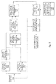
Fig 3 is the block diagram for the first embodiment of the present invention; and -
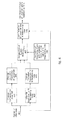
Fig 4 is the block diagram for the second embodiment of the present invention. - A channel estimation for the user signals of the local and the neighboring cells firstly needs to be made in the present invention. In the TD-SCDMA system, training sequence is launched so that the channel estimation is made at the receiving end. The training sequence signal em received can be expressed as:

wherein, M 0 represents the training sequence matrix of the local cell, with a dimension of 128x128; Mi,i =1,...,N represents the training sequence matrix ofthe N neighboring cells hoping to eliminate interference, with a dimension of 128x128, N can be set according to the practical needs. For example, considering the first level neighboring cell of the local cell, nm represents various interferences and noises, with a dimension of 128×1; h 0 represents the channel impulse response of the user of local cell, with a dimension of 128×1; hi,i=1,...,N represents the channel impulse responses of the users ofN neighboring cells, with a dimension of 128x1. - This invention aims at obtaining the estimation of h 0 and hi,i =1, ..., N through signal processing algorithm, thus the following two solutions can be employed:
- Channel Estimation Solution 1:
-
Fig1 is a schematic view for the embodiment of Channel Estimation Solution 1 as described in the invention:
-
- Step One, performing a preliminary estimation for hi, i = 0,...,N as follows:
 comprises the errors brought by the signals and noises from other cells, but the errors are significantly reduced by multiplying with M i -1; due to the particularity of the construction of matrix Mi , i=1,...,N, i.e. the particularity of rotate right, the Exp (2) can be done by using Fast Fourier Transform, which reduces computation load.
- Step Two, performing a post-channel processing forand obtaining the tap position of the user signal path, i.e. comparing the power of 128 taps
 (k), k=1,...,128 of
 with a threshold (the value of the threshold is related to the noise power), the taps with the power below the threshold being considered as noise and the value being set to be zero, the taps with the power above the threshold being considered as signals and the value being saved; supposing the number of the signal taps being L 0 after the post-channel process, then the signal tap position being
- Step Three, performing post-channel processing fori =1, ..., N, i.e. comparing the power of 128 taps
 (k), k =1, ...,128 of
 i =1, ..., N with a threshold, the taps with the power below the threshold being considered as noise and the value being set to be zero; the taps with the power above the threshold being considered as signals and the value being saved; obtaining the tap positions ofthe user signal paths as


- Step Four, performing a joint estimation for the channel impulse response of each said cell as follows:


- Generally speaking, steps one to three are for estimating time delay position of the user signal path of each said cell, and step 4 is for performing joint channel estimation for the users of multiple cells, and the channel estimation interference among each cell user is eliminated.
- Channel Estimation Solution 2:
-
Fig 2 is a schematic view for the embodiment of Channel Estimation Solution 2 as described in the invention. - Solution 2 is a simplification of Solution 1, more specifically, it reserves steps one to three of Solution 1 and discards step four. Step four of Solution 1 is discarded because it requires matrix inversion, and the matrix does not possess the property of rotate right, thus it can not simplify the computation through Fast Fourier Transform, resulting in a complicated computation. However, the discarding of step four also has shortcomings, because the channel estimationcalculated from Exp (2) includes errors brought by signals from other cells, which can be eliminated by step four.

- Ajoint detection needs to be performed for the user signals of the local cell and the N neighboring cells after the channel estimation. The system equation can be expressed as:

Wherein, Ai,i = 0, ...,N is system matrix for each cell and is constituted by the spread spectrum code, scrambling code and channel impulse responses of the users of each said cell. The scrambling code of the neighboring cell and the spread spectrum code of the user are obtained in the following two situations: Situation one, the neighboring cell and the local cell have the same base station, under such condition, the scrambling code of the neighboring cell and the spread spectrum code of the user can be exactly ascertained without using RNC (Radio network controller); Situation two, the neighboring cell and the local cell have different base stations, under such condition, the scrambling code of the neighboring cell and the spread spectrum code of the user can be obtained by RNC through signaling interaction. - When performing estimation for dcomp in Exp (4), Zero Forcing Block Linear Equalizer (ZE-BLE) or Minimum Mean Square Error Block Linear Equalizer (MMSE-BLE) estimation can be used as follows:
- Zero Forcing Block Linear Equalizer estimation:

- Minimum Mean Square Error Block Linear Equalizer estimation:

- If there are many user signals of the neighboring cells to be solved, causing that the column rank of matrix Acomp is larger than the row rank and the Exp (4) has infinite solutions, then the following steps can be taken to find out the unique solution:
- adding the number of receiving antennae to increase the row rank;
- or reducing the number of user signals of the neighboring cells to be solved so as to reduce the row rank, which, however, will increase the errors of (Exp (5) or (6));

- or adding restriction conditions to find out the unique solution, for example, the restriction condition can be that each user signal has the minimum mean square error in distance with regard to the constellation points of modulation constellation map.

- When taking the Channel Estimation Solution One, the steps of the whole scheme of the invention are as shown in
fig 3 , which is block diagram for the first embodiment of the whole technical scheme of the present invention: - Step 301: receiving sampling signals of chip-level;
-
Steps 302 and 303: performing preliminary channel estimation for the local cell and the N neighboring cells, as shown in Exp (2); - Step 304: performing post-channel processing for the preliminary channel estimation of the local cell, i.e. comparing the powers of 128 taps (k), k = 1,...,128 of
 with a threshold, the taps with the power below the threshold being considered as noise, and the values being set to be zero; the taps with the power above the threshold being considered as signals and the values being saved, and the obtained signal tap positions being
- Step 305: performing post-channel processing for channel estimation i=1,...,N of the N neighboring cells, i.e. comparing the powers of 128 taps
 (k), k=1,...,128 ofi=1,...,N with a threshold, the taps with the power below the threshold being considered as noise and the values being set to be zero; the taps with the power above the threshold being considered as signals and the values being saved, and the obtained signal tap positions being

- Step 306: combining the columns

- Step 307: performing joint channel estimation for the local cell and the neighboring cells, get the solution of as shown in Exp (3);

- Step 308: generating the scrambling code and the spread spectrum code of the local cell and the neighboring cells;
- Step 309: composing matrix Acomp using and the scrambling code of each cell, as well as the spread spectrum code of each cell user, as shown in Exp (4); and

- Step 310: performing the joint detection for the user signals of each cell and obtaining the symbol of each cell user, as shown in Exp (5) or (6).

- When taking the Channel Estimation Solution Two, the steps of the whole scheme are shown in
fig 4 , which is the block diagram for the second embodiment of the present invention: - Step 401: receiving sampling signals of chip-level;
-
Steps 402 and 403: performing preliminary channel estimation for the local cell and the neighboring cells, as shown in Exp (2); - Step 404: performing post-channel processing for the preliminary channel estimation of the local cell, i.e. comparing the powers of 128 taps (k), k = 1,...,128 of
 with a threshold, the taps with the power below the threshold being considered as noise and the values being set to be zero; the taps with the power above the threshold being considered as signals and the values being saved, the obtained signal tap positions being
- Step 405: performing post-channel processing for the channel estimation i =1,...,N of the N neighboring cells, i.e. comparing the powers of 128 taps
 (k), k =1, ...,128 ofi =1,...,N with a threshold, the taps with the power below the threshold being considered as noise and the value being set to be zero; the taps with the power above the threshold being considered as signals and the values being saved, the obtained signal tap positions being

- Step 406: generating the scrambling code and the spread spectrum code of the local cell and the neighboring cells;
- Step 407: composing matrix Acomp using and the scrambling code of each cell, as well as the spread spectrum code of each cell user, as shown in Exp (4); and

- Step 408: performing the joint detection for the user signals of each cell and obtaining the symbol of each cell user, as shown in Exp (5) or (6).

- The method for reducing the interference from neighboring cells provided by the present invention takes the minority high-power user signals from neighboring cells as the signals that can be demodulated, and adds them to the joint detection, therefore eliminates the interference caused by these high-power user signals of the neighboring cells. TD-SCDMA system is a time division system, in which, different users scatter in different time slots, and the maximum number of the users within the same time slot of one cell is eight. The number of high-power user signals in one time slot of neighboring cells (usually the users located at the edge of the local cell and neighboring cells) is usually small, so generally speaking, the computing load added by using the method of the present invention will not be too large.
- The method described in the present invention can not be only applied in base station, but mobile terminals as well, especially those mobile terminals located at the edge of the cells.
Claims (10)
- A suppression method for signal interference from users in neighboring cells, comprising following steps of:making a channel estimation for user signals of a local cell and neighboring cells to estimate channel impulse responses of the users of the local cell and the neighboring cells; andmaking a joint detection for the user signals from each said cell based on the channel impulse responses of each said cell and obtaining symbols for each cell user.
- The method of claim 1, wherein said step of the channel estimation comprises the following steps of:making a preliminary channel estimation for the local cell and the neighboring cells according to sampling signals of chip-level received; andestimating time delay position of signal path of each said cell user after performing a post-channel processing for preliminary channel estimation of the local cell and neighboring cells.
- The method of claim 2, further comprising the following steps of:making a joint estimation for the channel impulse response of each said cell in order to eliminate channel estimation interference among each cell user.
- The method of claim 3, wherein said step of the joint estimation further comprises the following steps of:constructing matrix Mcomp based on the time delay position of the signal path of each said cell user; andmaking the joint estimation for each said cell based on the matrix Mcomp.
- The method of claim 1, wherein said step of the joint detection comprises the following steps of:determining scrambling codes and spread spectrum codes for the local cell and the neighboring cells;composing matrix Acomp based on the channel impulse responses of each said cell as well as the scrambling codes and the spread spectrum codes; andmaking the joint detection for the user signals of each said cell based on said matrix Acomp and obtaining a user symbolof each said cell.

- The method of claim 2, wherein in said step of the preliminary channel estimation, a method used is as follows:
 i=1,...,N;

M 0 represents training sequence matrix of the local cell; Mi ,i=1,...,N represents the training sequence matrix ofN neighboring cells expecting to eliminate the interference; nm represents various interferences and noises; h 0 represents the channel impulse response of the users of the local cell; hi,i=1,..., N represents the channel impulse responses ofthe users ofthe N neighboring cells. - The method of claim 6, wherein in the step of performing post-channel processing for the preliminary channel estimation of the local cell and the neighboring cells, the step of post-channel processing for the local cell includes:comparing powers of 128 taps(k), k = 1,...,158 of
 with a threshold, the taps with the powers below the threshold being considered as noise and their values being set to be zeroes, the taps with the powers above the threshold being considered as signals and their values being saved;supposing a number of signal taps being L 0 after the post-channel processing, then positions of the signal taps being
 and the post-channel processing for the neighboring cells includes:comparing the powers of 128 taps(k),k=1,...,128 of
 i =1,...,N with a threshold, the taps with the powers below the threshold being considered as noise and their values being set to be zeroes, the taps with the powers above the threshold being considered as signals and their values being saved;obtaining the tap positions of the user signal paths being

- The method of claim 4, wherein in said step of the joint estimation, a method used is as follows:


is a composite channel impulse response, with the dimension of

- The method of claim 5, wherein in said step of the joint detection, its equation is represented as follows:

wherein, Ai ,i= 0,...,N represents a system matrix of each said cell and is constituted by the spread spectrum codes, the scrambling codes and the channel impulse responses of the users of each said cell;
when performing the estimation for dcomp , Zero Forcing Block Linear Equalizer or Minimum Mean Square Error Block Linear Equalizer can be employed, wherein,
Zero Forcing Block Linear Equalizer:

- The method of claim 5, wherein in said step of determining the scrambling codes and the spread spectrum codes of the local cell and the neighboring cells, when the neighboring cells and the local cell have different base stations, Radio network controller employs signaling interaction to obtain said scrambling codes and said spread spectrum codes.
Applications Claiming Priority (1)
| Application Number | Priority Date | Filing Date | Title |
|---|---|---|---|
| PCT/CN2005/001209 WO2007016811A1 (en) | 2005-08-08 | 2005-08-08 | Restrain method for signal interference from users in neighbor cells |
Publications (2)
| Publication Number | Publication Date |
|---|---|
| EP1921757A1 true EP1921757A1 (en) | 2008-05-14 |
| EP1921757A4 EP1921757A4 (en) | 2010-07-07 |
Family
ID=37727072
Family Applications (1)
| Application Number | Title | Priority Date | Filing Date |
|---|---|---|---|
| EP05772472A Withdrawn EP1921757A4 (en) | 2005-08-08 | 2005-08-08 | Restrain method for signal interference from users in neighbor cells |
Country Status (3)
| Country | Link |
|---|---|
| EP (1) | EP1921757A4 (en) |
| CN (1) | CN101133562B (en) |
| WO (1) | WO2007016811A1 (en) |
Cited By (3)
| Publication number | Priority date | Publication date | Assignee | Title |
|---|---|---|---|---|
| WO2011092257A1 (en) * | 2010-01-29 | 2011-08-04 | Icera Inc | A cellular communications system |
| US8126451B2 (en) | 2007-10-31 | 2012-02-28 | Icera, Inc. | Synchronous CDMA communication system |
| US8577304B2 (en) | 2007-10-31 | 2013-11-05 | Icera, Inc. | Synchronous CDMA communication system |
Families Citing this family (7)
| Publication number | Priority date | Publication date | Assignee | Title |
|---|---|---|---|---|
| CN101605382B (en) * | 2008-06-13 | 2011-03-30 | 大唐移动通信设备有限公司 | Method and device for coordinating intercell interference |
| CN101741412B (en) * | 2008-11-19 | 2013-06-05 | 中兴通讯股份有限公司 | Construction method of spreading codes and multi-community joint detection method |
| CN102647387B (en) * | 2012-04-09 | 2015-09-09 | 华为技术有限公司 | The removing method of co-channel interference and device |
| CN103905086B (en) * | 2012-12-26 | 2016-07-20 | 联芯科技有限公司 | Associated detecting method and system |
| CN106162726A (en) * | 2015-03-25 | 2016-11-23 | 鼎桥通信技术有限公司 | A kind of multi-cell joint detection method in TD-SCDMA system |
| CN111245761B (en) * | 2020-01-09 | 2022-05-31 | 北京航空航天大学杭州创新研究院 | NOMA uplink self-adaptive data receiving method |
| CN114553338B (en) * | 2022-02-25 | 2024-07-16 | 哲库科技(北京)有限公司 | Method and device for determining interference signal, electronic equipment and readable storage medium |
Family Cites Families (5)
| Publication number | Priority date | Publication date | Assignee | Title |
|---|---|---|---|---|
| US6339612B1 (en) * | 1998-02-09 | 2002-01-15 | Motorola, Inc. | Method and apparatus for joint detection of data in a direct sequence spread spectrum communications system |
| JP2000261412A (en) * | 1999-03-06 | 2000-09-22 | Matsushita Electric Ind Co Ltd | Interference signal canceller |
| CN1283110C (en) * | 2002-07-10 | 2006-11-01 | 西门子(中国)有限公司 | Disturbance power estimation apparatus and method and disturbance power detecting system |
| US20040116122A1 (en) | 2002-09-20 | 2004-06-17 | Interdigital Technology Corporation | Enhancing reception using intercellular interference cancellation |
| CN1170389C (en) * | 2002-11-13 | 2004-10-06 | 大唐移动通信设备有限公司 | Method for using long subzone codes in combined detection system |
-
2005
- 2005-08-08 EP EP05772472A patent/EP1921757A4/en not_active Withdrawn
- 2005-08-08 WO PCT/CN2005/001209 patent/WO2007016811A1/en not_active Ceased
- 2005-08-08 CN CN2005800487581A patent/CN101133562B/en not_active Expired - Fee Related
Cited By (6)
| Publication number | Priority date | Publication date | Assignee | Title |
|---|---|---|---|---|
| US8126451B2 (en) | 2007-10-31 | 2012-02-28 | Icera, Inc. | Synchronous CDMA communication system |
| US8577304B2 (en) | 2007-10-31 | 2013-11-05 | Icera, Inc. | Synchronous CDMA communication system |
| WO2011092257A1 (en) * | 2010-01-29 | 2011-08-04 | Icera Inc | A cellular communications system |
| GB2489636A (en) * | 2010-01-29 | 2012-10-03 | Icera Llc | A cellular communications system |
| US9184785B2 (en) | 2010-01-29 | 2015-11-10 | Icera Inc. | Cellular communications system |
| GB2489636B (en) * | 2010-01-29 | 2018-01-24 | Nvidia Tech Uk Limited | A cellular communications system |
Also Published As
| Publication number | Publication date |
|---|---|
| EP1921757A4 (en) | 2010-07-07 |
| CN101133562B (en) | 2010-10-13 |
| WO2007016811A1 (en) | 2007-02-15 |
| CN101133562A (en) | 2008-02-27 |
Similar Documents
| Publication | Publication Date | Title |
|---|---|---|
| EP1391048B1 (en) | Fast joint detection | |
| US9763177B1 (en) | False cell filtering during cell search | |
| JP2008515252A (en) | Multi-cell joint detection method for time slot CDMA system | |
| US8937984B2 (en) | Method and device for eliminating interference in mobile communication system | |
| EP2834920B1 (en) | Soft-bit generation and channel estimation for interference cancellation using decoder output | |
| EP1921757A1 (en) | Restrain method for signal interference from users in neighbor cells | |
| CN106789760A (en) | A kind of jamproof single carrier channel is estimated and equalization methods and device | |
| CN101312359B (en) | Apparatus and method for multi-cell combined channel estimation and multi-cell combined detection | |
| CN101494468A (en) | Estimation method and device for multi-district united channel | |
| CN101931491B (en) | Data processing device and method for processing data thereby | |
| KR20050092127A (en) | Channel estimating method for multi-set of code in slotted cdma system | |
| US20100183094A1 (en) | Reception device and reception method | |
| CN1330101C (en) | A combined detection method for decreasing complexity in mobile communication system | |
| CN103379048B (en) | Channel estimate and detection method and base station | |
| CN102201833B (en) | Terminal multi-cell joint detection method for time division synchronous code division multiple access cluster system | |
| EP2485417A1 (en) | Method and device for selecting noise path | |
| CN102664835A (en) | Multicell channel estimation method based on interference elimination route by route | |
| US20040131107A1 (en) | Adaptive turbo multiuser detection for HSDPA/TDD CDMA with unknown interferers | |
| CN102387103B (en) | Detection method and device for spread spectrum factors in co-frequency neighbor cells of time division-synchronization code division multiple access (TD-SCDMA) system | |
| CN102739282B (en) | Multi-antenna combined detection system of TD-SCDMA system and multi-antenna combined detection method thereof | |
| CN100459446C (en) | A Channel Path Estimation Search Method for Multipath Fading Channel | |
| CN1953343B (en) | A method to check soft bit of output generated channel encoder by linear joint detection | |
| US8548005B2 (en) | Technique for switching between 1x and 2x oversampling rate in a TD-SCDMA receiver | |
| US6944205B2 (en) | Method of determining an acquisition indicator bit in a communication system | |
| US7912154B2 (en) | Baseband process method based on doubling sampling |
Legal Events
| Date | Code | Title | Description |
|---|---|---|---|
| PUAI | Public reference made under article 153(3) epc to a published international application that has entered the european phase |
Free format text: ORIGINAL CODE: 0009012 |
|
| 17P | Request for examination filed |
Effective date: 20080228 |
|
| AK | Designated contracting states |
Kind code of ref document: A1 Designated state(s): AT BE BG CH CY CZ DE DK EE ES FI FR GB GR HU IE IS IT LI LT LU LV MC NL PL PT RO SE SI SK TR |
|
| A4 | Supplementary search report drawn up and despatched |
Effective date: 20100604 |
|
| 17Q | First examination report despatched |
Effective date: 20110711 |
|
| DAX | Request for extension of the european patent (deleted) | ||
| STAA | Information on the status of an ep patent application or granted ep patent |
Free format text: STATUS: EXAMINATION IS IN PROGRESS |
|
| GRAP | Despatch of communication of intention to grant a patent |
Free format text: ORIGINAL CODE: EPIDOSNIGR1 |
|
| STAA | Information on the status of an ep patent application or granted ep patent |
Free format text: STATUS: GRANT OF PATENT IS INTENDED |
|
| RIC1 | Information provided on ipc code assigned before grant |
Ipc: H04L 25/03 20060101ALI20170824BHEP Ipc: H04L 25/02 20060101ALI20170824BHEP Ipc: H04B 1/7105 20110101AFI20170824BHEP |
|
| INTG | Intention to grant announced |
Effective date: 20170926 |
|
| STAA | Information on the status of an ep patent application or granted ep patent |
Free format text: STATUS: THE APPLICATION IS DEEMED TO BE WITHDRAWN |
|
| 18D | Application deemed to be withdrawn |
Effective date: 20180207 |