EP1921707A1 - Electronically scanned hemispheric antenna - Google Patents
Electronically scanned hemispheric antenna Download PDFInfo
- Publication number
- EP1921707A1 EP1921707A1 EP07115767A EP07115767A EP1921707A1 EP 1921707 A1 EP1921707 A1 EP 1921707A1 EP 07115767 A EP07115767 A EP 07115767A EP 07115767 A EP07115767 A EP 07115767A EP 1921707 A1 EP1921707 A1 EP 1921707A1
- Authority
- EP
- European Patent Office
- Prior art keywords
- radiators
- radiator
- antenna
- antenna according
- radomes
- Prior art date
- Legal status (The legal status is an assumption and is not a legal conclusion. Google has not performed a legal analysis and makes no representation as to the accuracy of the status listed.)
- Withdrawn
Links
- 238000003491 array Methods 0.000 claims description 23
- 239000002826 coolant Substances 0.000 claims description 8
- 239000000463 material Substances 0.000 description 3
- 241001465754 Metazoa Species 0.000 description 1
- 238000001816 cooling Methods 0.000 description 1
- 239000012809 cooling fluid Substances 0.000 description 1
- 239000007788 liquid Substances 0.000 description 1
- 238000004519 manufacturing process Methods 0.000 description 1
- 239000002244 precipitate Substances 0.000 description 1
- 239000003507 refrigerant Substances 0.000 description 1
- XLYOFNOQVPJJNP-UHFFFAOYSA-N water Substances O XLYOFNOQVPJJNP-UHFFFAOYSA-N 0.000 description 1
Images

Classifications
-
- H—ELECTRICITY
- H01—ELECTRIC ELEMENTS
- H01Q—ANTENNAS, i.e. RADIO AERIALS
- H01Q21/00—Antenna arrays or systems
- H01Q21/06—Arrays of individually energised antenna units similarly polarised and spaced apart
- H01Q21/061—Two dimensional planar arrays
- H01Q21/065—Patch antenna array
-
- H—ELECTRICITY
- H01—ELECTRIC ELEMENTS
- H01Q—ANTENNAS, i.e. RADIO AERIALS
- H01Q1/00—Details of, or arrangements associated with, antennas
- H01Q1/02—Arrangements for de-icing; Arrangements for drying-out ; Arrangements for cooling; Arrangements for preventing corrosion
-
- H—ELECTRICITY
- H01—ELECTRIC ELEMENTS
- H01Q—ANTENNAS, i.e. RADIO AERIALS
- H01Q1/00—Details of, or arrangements associated with, antennas
- H01Q1/12—Supports; Mounting means
- H01Q1/22—Supports; Mounting means by structural association with other equipment or articles
- H01Q1/24—Supports; Mounting means by structural association with other equipment or articles with receiving set
- H01Q1/241—Supports; Mounting means by structural association with other equipment or articles with receiving set used in mobile communications, e.g. GSM
- H01Q1/246—Supports; Mounting means by structural association with other equipment or articles with receiving set used in mobile communications, e.g. GSM specially adapted for base stations
-
- H—ELECTRICITY
- H01—ELECTRIC ELEMENTS
- H01Q—ANTENNAS, i.e. RADIO AERIALS
- H01Q1/00—Details of, or arrangements associated with, antennas
- H01Q1/27—Adaptation for use in or on movable bodies
- H01Q1/28—Adaptation for use in or on aircraft, missiles, satellites, or balloons
-
- H—ELECTRICITY
- H01—ELECTRIC ELEMENTS
- H01Q—ANTENNAS, i.e. RADIO AERIALS
- H01Q1/00—Details of, or arrangements associated with, antennas
- H01Q1/40—Radiating elements coated with or embedded in protective material
Definitions
- the invention relates generally to radar and communications antennas and more particularly to a phased array antenna for use with aircraft.
- antennas used on aircraft, ships and vehicles require radomes to protect radiating elements from wind and water. Radomes strong enough to withstand weather and bird strikes typically have thick walls, which reduce their RF transmissivity and hence their electrical performance but increasing their cost and weight.
- a simple and inexpensive antenna that provided hemispherical or spherical coverage without requiring a lossy and expensive radome, and which could be on aircraft, ships and terrestrial vehicles would be an improvement over the prior art.
- an antenna for mounting on the exterior surface of an aircraft, ship or other vehicle which is comprised of three phased array radiators.
- the arrays are mounted to a frame such that the radiators and the frame are in the shape of a truncated pyramid.
- Each radiator has a center axis that is normal to the radiator.
- Each radiator has a radar scan angle substantially equal to ⁇ 60 degrees relative to the center axis.
- the radiators are mounted to a frame such that the angle between adjacent center axes forms an angle of 120 degrees.
- an antenna comprising first, second and third phased array radiators (hereafter “radiators”), each of said radiators having an axis that is normal to the radiator, each radiator having a scan angle substantially equal to ⁇ 60 degrees relative to each radiator's center axis, the radiators being positioned on the circumference of a geometric circle.
- the geometric circle may lie in a substantially horizontal plane.
- the first, second and third phased array radiators may be substantially planar.
- the center axes of the first, second and third phased array radiators may be upwardly inclined with respect to the horizontal plane.
- the first, second and third phased array radiators may have vertical and azimuth scan angles that are both substantially equal to ⁇ 60 degrees relative to the radiator's axis so that radar signals from the three radiators can be controlled to be swept over a hemisphere.
- the first, second and third planar phased array radiators may enclose a substantially triangular shape.
- the first, second and third planar phased array radiators may enclose a truncated pyramid.
- the first, second and third planar phased array radiators may abut each other such that the sum of the angles they enclose equal 180 degrees.
- Each radiator may be comprised of electromagnetic signal radiating elements.
- a coolant may be provided that absorbs thermal energy emitted from these electromagnetic signal radiating elements.
- an antenna comprising first, second and third phased array planar radiators (hereafter "radiators"), each of said planar radiators having a center axis that is normal to the radiator, each radiator having an azimuth scan angle substantially equal to ⁇ 60 degrees relative to each radiator's center axis, and each radiator has a vertical scan angle substantially equal to ⁇ 60 degrees relative to each radiator's center axis, the radiators being positioned on the circumference of a geometric circle.
- the geometric circle suitably lies in a substantially horizontal plane.
- the center axes of the first, second and third phased array radiators may be upwardly inclined with respect to the horizontal plane, at the same angle.
- the first, second an third planar phased array radiators may enclose a volume that is substantially in the shape of a truncated pyramid.
- the first, second an third planar phased array radiators may abut each other such that the sum of the angles they enclose equal 180 degrees.
- Each radiator may be comprised of electromagnetic signal radiating elements; and a coolant that absorbs thermal energy emitted from the electromagnetic signal radiating elements.
- an antenna comprising: first, second and third planar arrays, each of said planar arrays being substantially planar and having a geometric center axis that extends substantially perpendicular from the geometric center of a radiating face of each radiator, each radiator having vertical and azimuth scan angles that are both substantially equal to ⁇ 60 degrees relative to each radiator's center axis, the planar arrays being positioned on the circumference of a geometric circle; and first, second and third, radar-signal transmissive radomes extending over the radiating faces of the first, second and third planar arrays respectively such that the planar arrays are behind the radomes and the radomes are mechanically supported by the planar arrays.
- the geometric circle lies in a substantially horizontal plane.
- the first, second and third planar arrays may be substantially planar and the radomes substantially conform to the planar arrays.
- the center axes of the first, second and third planar arrays are upwardly inclined with respect to the horizontal plane, at substantially the same angle.
- the first, second and third planar arrays may emit electromagnetic signals from each radiator that can be swept over a hemisphere.
- the first, second an third planar planar arrays may abut each other such that the first, second and third planar arrays enclose a substantially triangular shape.
- Each radiator may be comprised of electromagnetic signal radiating elements; and a coolant that absorbs thermal energy emitted from the electromagnetic signal radiating elements.
- an antenna comprising first, second and third phased array radiators (hereafter “radiators”), each of said radiators being substantially planar and having a electromagnetic signal radiating face having geometric center axis that extends perpendicularly from the geometric center of the radiating face of each radiator, each radiator having a vertical and azimuth scan angle substantially equal to ⁇ 60 degrees relative to each radiator's center axis; first, second and third, radar-signal transmissive radomes that conform to and which extend over the radiating faces of the first, second and third radiators respectively such that the radiators are behind the radomes, the radomes being mechanically supported by the radiators; and a three-sided, truncated-pyramidal-shaped fairing having first, second and third inclined faces that receive the first, second and third radomes.
- radiators phased array radiators
- the sides of the truncated-pyramidal-shaped fairing may be inclined at a first predetermined angle.
- the first, second and third phased array radiators may be substantially planar with the radomes conforming to the radiators.
- the center axes of the first, second and third phased array radiators may be upwardly inclined with respect to the horizontal plane, at the same angle.
- the first, second and third phased array radiators are suitably capable of emitting electromagnetic signals from each radiator that can be swept over a hemisphere.
- each radiator is comprised of electromagnetic signal radiating elements; and a coolant that absorbs thermal energy emitted from the electromagnetic signal radiating elements.
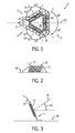
- FIG. 1 shows a top view of an electronically scanned hemispheric antenna 10 and FIG. 2 shows a side view of the antenna 10.
- the antenna 10 is comprised of an airfoil or fairing 11 in the shape of a truncated pyramid in that it has three inclined sides 2, 4 and 6 joined to each other but also joined to a flat top 15.
- the three sides 2, 4and 6 also rest on a flat surface 28, such as a surface of an airplane, helicopter or terrestrial vehicle.
- the three inclined sides 2, 4 and 6 of the fairing 11 accommodate three, inclined phased array radiators 12, 14 and 16.
- Each of the radiators 12, 14 and 16 is substantially planar and has a geometric center axis that is normal or substantially normal to a geometric plane in which the corresponding radiator lies.
- the axes of the radiators 12, 14 and 16 are identified in the figures by reference numerals 18, 20 and 22 respectively. Since each center axis 18, 20 and 22 is normal to its corresponding radiator (12, 14 and 16 respectively), each center axis forms a geometric angle with adjacent axes such that the projected angle, on plane 28, between any two adjacent axes is one-hundred twenty degrees (120 degrees).
- the sum of the interior angles of a triangle equals 180 degrees. Therefore, the sum of the angles formed between the radiators 12, 14 and 16 is equal to 180 degrees.
- FIG. 3 depicts the cross section of one of the phased array radiators 14 as it lies in one of the sides 4.
- the cross sections of the other phased array radiators are identical to the cross section depicted in FIG. 2.
- the phased array radiators are inclined relative to the antenna's flat top 15 and relative to the surface 28 by an elevation angle 29. Since the flat top 15 and the surface 28 are depicted in FIG. 3 as being parallel to each other, the angle between the axes 18, 20 or 22 and the top surface 15 or the "bottom" surface 28 is the same.
- Each radiator 12, 14 and 16 is a phased array radiator, the operation of which is well-known to those of ordinary skill in radar.
- Each radiator 12, 14 and 16 has a radar azimuth and elevation scan angle that is substantially equal to ⁇ 60 degrees relative to each radiator's center axis 18, 20 and 22 such that each radiator 12, 14 and 16 is capable of scanning an azimuth and elevation angle of up to one hundred twenty degrees (120 degrees).
- phased array radiators 12, 14 and 16 that each sweep a different 120 degree azimuth angle, and since each radiator 12, 14 and 16 can sweep an elevation angle of ⁇ 60 degrees from its respective center axis 18, 20, 22, , the three phased array radiators 12, 14 and 16 enable the antenna to electronically scan a full, or substantially full, hemisphere.
- the radiators 12, 14 and 16 are mounted to a pyramidal-shaped frame 31 (shown in FIG. 5 but not in FIG. 1) such that the lower apexes of each of the radiators 12, 14 and 16 lie on the circumference of a geometric circle that is centered about the geometric triangle enclosed by the sides 2, 4 and 6 and/or the radiators 12, 14 and 16.
- the radiators are therefore considered to lie "on" the circumference of a circle, however, only the apexes or corners of the radiator's are actually on a geometric circle.
- FIG. 4 there is shown an airplane 40 with one of the antennas 10 shown as being mounted on top of the fuselage of the airplane 40.
- a second antenna 10 mounted on the underside or bottom of the fuselage can provide the ability to scan a second hemisphere, except for the small space between the antenna on top of the fuselage and the antenna on the bottom of the fuselage.
- FIG. 4 depicts the antenna 10 mounted on the fuselage
- alternate embodiments of the invention disclosed and claimed herein include mounting one or more of the antennas on an upper and/or lower wing surface by which a full hemispherically-shaped volume could be scanned by the arrays 12, 14 and 16 in the respective antennas.
- the antennas 10 could also be mounted on a helicopter, ship or a terrestrial vehicle to provide a hemispheric radar or communications antenna to helicopters, ships or terrestrial vehicles.
- FIG. 5 there is shown an exploded view of the antenna 10.
- planar arrays 12, 14 and 16 which can also be considered as electromagnetic signal radiating elements, are mounted to a frame 31 in the shape of a truncated pyramid in that the frame 31 has three planar sides 30, 32, and 34 that are inclined relative to flat, top and bottom surfaces.
- Each of the sides 30, 32 and 34 can include an integrated cooling channel or panel 42 to cool the arrays 12, 14 and 16 if the power level emitted from the arrays 12, 14 and 16 is so great that it heats or overheats the frame 31, the fairing material or the material from which the arrays are constructed.
- a cooling fluid (not shown) circulates through the channels 42 to remove heat from the planar arrays 12, 14 and 16 that are mounted against the sides 30, 32 and 34 to be in thermal contact with the sides. Heat from the arrays 12, 14 and 16 travels from the arrays into the planar sides and then into the coolant by conduction, such that the coolant ultimately absorbs thermal energy emitted from the radiating elements 12, 14 and 16.
- the coolant circulated through the channels 42 could include any appropriate refrigerant gas or liquid.
- a ventilated or unventilated heat sink is used with one or more such heat sinks being in thermal communication with its corresponding radiator element 12, 14 and 16.
- substantially planar radar-transmissive radomes that cover or "extend over" the radiating surfaces 12, 14 and 16. Radar-transmissive radomes and the materials they are usually constructed from are well known to those of ordinary skill in the art. Radomes extending over the arrays are useful to protect the radiators 12, 14 and 16 from damage that can be caused by impacts with precipitate, animals as well as damage that can be caused by impacts with small objects.
- the radomes used in one embodiment were substantially flush with the surface of the fairing that covers the radiator elements 12, 14 and 16.
- phased array elements 12, 14 and 16 that are capable of beam steering or directing a radar or communications beam up to 120 degrees.
Landscapes
- Engineering & Computer Science (AREA)
- Physics & Mathematics (AREA)
- Astronomy & Astrophysics (AREA)
- Aviation & Aerospace Engineering (AREA)
- General Physics & Mathematics (AREA)
- Remote Sensing (AREA)
- Computer Networks & Wireless Communication (AREA)
- Variable-Direction Aerials And Aerial Arrays (AREA)
- Radar Systems Or Details Thereof (AREA)
Abstract
Description
- The Government of the United States of America has rights in this invention pursuant to Contract No. F19620-00-C-0002 awarded by the United States Air Force.
- The invention relates generally to radar and communications antennas and more particularly to a phased array antenna for use with aircraft.
- There is growing commercial as well as military need for wideband radar and communications on aircraft, ships and ground-based craft. In many of these applications, low-height antennae are needed that can provide spherical or hemispherical coverage.
- Low-cost electronically scanned antennas exist but these prior art antennas are planar and have scan angles limited to approximately ± 60 degrees. At 60 degrees, the performance of these antennas is very poor.
- As is known, antennas used on aircraft, ships and vehicles require radomes to protect radiating elements from wind and water. Radomes strong enough to withstand weather and bird strikes typically have thick walls, which reduce their RF transmissivity and hence their electrical performance but increasing their cost and weight. A simple and inexpensive antenna that provided hemispherical or spherical coverage without requiring a lossy and expensive radome, and which could be on aircraft, ships and terrestrial vehicles would be an improvement over the prior art.
- There is provided an antenna for mounting on the exterior surface of an aircraft, ship or other vehicle, which is comprised of three phased array radiators. The arrays are mounted to a frame such that the radiators and the frame are in the shape of a truncated pyramid.
- Each radiator has a center axis that is normal to the radiator. Each radiator has a radar scan angle substantially equal to ± 60 degrees relative to the center axis. The radiators are mounted to a frame such that the angle between adjacent center axes forms an angle of 120 degrees.
- Since each radiator has a scan angle substantially equal to ± 60 degrees relative to each radiator's center axis, and since the radiators are positioned on the circumference of a geometric circle, three of the radiators can sweep an azimuth angle of 360 degrees and an elevation angle of +/- 60 degrees = 120 degrees. A full hemisphere can be swept by the three antennas.
- Because of their truncated pyramid shape, their mounting arrange provides a robust, wind-resistant structure with flush mounted radomes protecting each of the three radiating surfaces. A hemispherical radome is not needed.
- In one embodiment, an antenna is provided comprising first, second and third phased array radiators (hereafter "radiators"), each of said radiators having an axis that is normal to the radiator, each radiator having a scan angle substantially equal to ± 60 degrees relative to each radiator's center axis, the radiators being positioned on the circumference of a geometric circle. The geometric circle may lie in a substantially horizontal plane. The first, second and third phased array radiators may be substantially planar. The center axes of the first, second and third phased array radiators may be upwardly inclined with respect to the horizontal plane. The first, second and third phased array radiators may have vertical and azimuth scan angles that are both substantially equal to ± 60 degrees relative to the radiator's axis so that radar signals from the three radiators can be controlled to be swept over a hemisphere. The first, second and third planar phased array radiators may enclose a substantially triangular shape. The first, second and third planar phased array radiators may enclose a truncated pyramid. The first, second and third planar phased array radiators may abut each other such that the sum of the angles they enclose equal 180 degrees. Each radiator may be comprised of electromagnetic signal radiating elements. A coolant may be provided that absorbs thermal energy emitted from these electromagnetic signal radiating elements.
- In another embodiment, an antenna is provided comprising first, second and third phased array planar radiators (hereafter "radiators"), each of said planar radiators having a center axis that is normal to the radiator, each radiator having an azimuth scan angle substantially equal to ± 60 degrees relative to each radiator's center axis, and each radiator has a vertical scan angle substantially equal to ± 60 degrees relative to each radiator's center axis, the radiators being positioned on the circumference of a geometric circle. The geometric circle suitably lies in a substantially horizontal plane. The center axes of the first, second and third phased array radiators may be upwardly inclined with respect to the horizontal plane, at the same angle. The first, second an third planar phased array radiators may enclose a volume that is substantially in the shape of a truncated pyramid. The first, second an third planar phased array radiators may abut each other such that the sum of the angles they enclose equal 180 degrees. Each radiator may be comprised of electromagnetic signal radiating elements; and a coolant that absorbs thermal energy emitted from the electromagnetic signal radiating elements.
- In yet another embodiment, an antenna is provided comprising: first, second and third planar arrays, each of said planar arrays being substantially planar and having a geometric center axis that extends substantially perpendicular from the geometric center of a radiating face of each radiator, each radiator having vertical and azimuth scan angles that are both substantially equal to ± 60 degrees relative to each radiator's center axis, the planar arrays being positioned on the circumference of a geometric circle; and first, second and third, radar-signal transmissive radomes extending over the radiating faces of the first, second and third planar arrays respectively such that the planar arrays are behind the radomes and the radomes are mechanically supported by the planar arrays. Suitably, the geometric circle lies in a substantially horizontal plane. The first, second and third planar arrays may be substantially planar and the radomes substantially conform to the planar arrays. Suitably, the center axes of the first, second and third planar arrays are upwardly inclined with respect to the horizontal plane, at substantially the same angle. The first, second and third planar arrays may emit electromagnetic signals from each radiator that can be swept over a hemisphere. The first, second an third planar planar arrays may abut each other such that the first, second and third planar arrays enclose a substantially triangular shape. Each radiator may be comprised of electromagnetic signal radiating elements; and a coolant that absorbs thermal energy emitted from the electromagnetic signal radiating elements.
- In yet another embodiment an antenna is provided comprising first, second and third phased array radiators (hereafter "radiators"), each of said radiators being substantially planar and having a electromagnetic signal radiating face having geometric center axis that extends perpendicularly from the geometric center of the radiating face of each radiator, each radiator having a vertical and azimuth scan angle substantially equal to ± 60 degrees relative to each radiator's center axis; first, second and third, radar-signal transmissive radomes that conform to and which extend over the radiating faces of the first, second and third radiators respectively such that the radiators are behind the radomes, the radomes being mechanically supported by the radiators; and a three-sided, truncated-pyramidal-shaped fairing having first, second and third inclined faces that receive the first, second and third radomes. The sides of the truncated-pyramidal-shaped fairing may be inclined at a first predetermined angle. The first, second and third phased array radiators may be substantially planar with the radomes conforming to the radiators. The center axes of the first, second and third phased array radiators may be upwardly inclined with respect to the horizontal plane, at the same angle. The first, second and third phased array radiators are suitably capable of emitting electromagnetic signals from each radiator that can be swept over a hemisphere. Suitably, each radiator is comprised of electromagnetic signal radiating elements; and a coolant that absorbs thermal energy emitted from the electromagnetic signal radiating elements.
-
- FIG. 1 is a top view of an electronically scanned hemispheric antenna;
- FIG. 2 is a side view of the antenna shown in FIG. 1;
- FIG. 3 is a cross-sectional view of one of the panels or sides of the antenna shown in FIG. 1 and FIG. 2;
- FIG. 4 illustrates an application for the antenna, namely its attachment and use with an airplane; and
- FIG. 5 shows an exploded view of the antenna depicted in each of FIGS. 1-4.
- FIG. 1 shows a top view of an electronically scanned
hemispheric antenna 10 and FIG. 2 shows a side view of theantenna 10. As can be seen in FIGS. 1 and 2, theantenna 10 is comprised of an airfoil or fairing 11 in the shape of a truncated pyramid in that it has threeinclined sides flat top 15. The three sides 2,4and 6 also rest on aflat surface 28, such as a surface of an airplane, helicopter or terrestrial vehicle. - The three
inclined sides fairing 11 accommodate three, inclinedphased array radiators radiators radiators reference numerals center axis plane 28, between any two adjacent axes is one-hundred twenty degrees (120 degrees). - The three
radiators sides radiators - FIG. 3 depicts the cross section of one of the phased
array radiators 14 as it lies in one of thesides 4. (The cross sections of the other phased array radiators are identical to the cross section depicted in FIG. 2.) As can be see in FIG. 3, the phased array radiators are inclined relative to the antenna's flat top 15 and relative to thesurface 28 by anelevation angle 29. Since theflat top 15 and thesurface 28 are depicted in FIG. 3 as being parallel to each other, the angle between theaxes top surface 15 or the "bottom"surface 28 is the same. - Each
radiator radiator center axis radiator - Since there are three phased
array radiators radiator respective center axis array radiators - Referring to FIG. 1 and FIG. 5, the
radiators radiators sides radiators - Referring now to FIG. 4 there is shown an
airplane 40 with one of theantennas 10 shown as being mounted on top of the fuselage of theairplane 40. Asecond antenna 10 mounted on the underside or bottom of the fuselage (not shown) can provide the ability to scan a second hemisphere, except for the small space between the antenna on top of the fuselage and the antenna on the bottom of the fuselage. - While the embodiment shown in FIG. 4 depicts the
antenna 10 mounted on the fuselage, alternate embodiments of the invention disclosed and claimed herein include mounting one or more of the antennas on an upper and/or lower wing surface by which a full hemispherically-shaped volume could be scanned by thearrays antennas 10 could also be mounted on a helicopter, ship or a terrestrial vehicle to provide a hemispheric radar or communications antenna to helicopters, ships or terrestrial vehicles. - Referring now to FIG. 5 there is shown an exploded view of the
antenna 10. - The
planar arrays frame 31 in the shape of a truncated pyramid in that theframe 31 has threeplanar sides - Each of the
sides arrays arrays frame 31, the fairing material or the material from which the arrays are constructed. In one embodiment, a cooling fluid (not shown) circulates through the channels 42 to remove heat from theplanar arrays sides arrays elements - The coolant circulated through the channels 42 could include any appropriate refrigerant gas or liquid. In an alternate embodiment, a ventilated or unventilated heat sink is used with one or more such heat sinks being in thermal communication with its
corresponding radiator element radiators radiator elements - Those of ordinary skill in the art will appreciate the cost effectiveness of using multiple phased
array elements - Those of ordinary skill in the art will also recognize the value of not using a rotating radome as the prior art teaches but instead using a low-cost and low-profile, fixed, i.e., non-rotating radome with emitted signals being electronically steered. The truncated pyramidal-shaped
antenna 10 depicted in the drawings provides superior beam scan angles in a low-profile antenna that is more rugged than prior art rotating radomes and less expensive to manufacture. - It should be borne in mind that the description above is purposes of illustration only and not for purposes of limitation. The true scope of the invention is defined by the appurtenant claims.
Claims (18)
- An antenna comprising:first, second and third phased array radiators (hereafter "radiators"), each of said radiators having an axis that is normal to the radiator, each radiator having a scan angle substantially equal to ± 60 degrees relative to each radiator's axis, the radiators being positioned on the circumference of a geometric circle.
- An antenna according to claim 1, wherein the axis of each radiator is the center axis of each radiator.
- An antenna according to claim 1 or claim 2, wherein the scan angle is an azimuth scan angle.
- An antenna according to any preceding claim, wherein the geometric circle lies in a substantially horizontal plane.
- An antenna according to any preceding claim, wherein the axes of the first, second and third radiators are upwardly inclined with respect to the horizontal plane.
- The antenna of claim 5 wherein the center axes are upwardly inclined with respect to the horizontal plane at substantially the same angle.
- An antenna according to any preceding claim, wherein the first, second and third radiators are substantially planar.
- An antenna according to any preceding claim, wherein the first, second and third radiators have a vertical scan angles substantially equal to ± 60 degrees relative to the radiator's axis.
- An antenna according to any preceding claim, wherein the first, second and third radiators emit electromagnetic signals from each radiator that can be swept over a hemisphere.
- An antenna according to any preceding claim wherein the first, second and third radiators enclose a substantially triangular shape.
- An antenna according to any preceding claim wherein the first, second and third radiators enclose a volume that is substantially in the shape of a truncated pyramid.
- An antenna according to any preceding claim wherein the first, second and third radiators abut each other such that the sum of the angles they enclose equal 180 degrees.
- An Antenna according to any preceding claim further comprising first, second and third, radar-signal transmissive radomes extending over the radiating faces of the radiators respectively such that the planar arrays are behind the radomes and the radomes are mechanically supported by the radiators.
- The antenna of claim 13 wherein the radomes substantially conform to the radiators.
- An antenna according to any preceding claim comprising a three-sided, truncated-pyramidal-shaped fairing having first, second and third inclined faces that receive the first, second and third radomes.
- The antenna of claim 15 wherein the sides of the truncated-pyramidal-shaped fairing are inclined at a first predetermined angle.
- The antenna of claim 15 and 16 wherein the first, second and third radiators are substantially planar and the radomes conform to the radiators.
- An antenna according to any preceding claim, wherein each radiator is comprised of:electromagnetic signal radiating elements; anda coolant that absorbs thermal energy emitted from the electromagnetic signal radiating elements.
Applications Claiming Priority (1)
| Application Number | Priority Date | Filing Date | Title |
|---|---|---|---|
| US11/594,320 US20080106482A1 (en) | 2006-11-08 | 2006-11-08 | Electronically scanned hemispheric antenna |
Publications (1)
| Publication Number | Publication Date |
|---|---|
| EP1921707A1 true EP1921707A1 (en) | 2008-05-14 |
Family
ID=39007288
Family Applications (1)
| Application Number | Title | Priority Date | Filing Date |
|---|---|---|---|
| EP07115767A Withdrawn EP1921707A1 (en) | 2006-11-08 | 2007-09-05 | Electronically scanned hemispheric antenna |
Country Status (2)
| Country | Link |
|---|---|
| US (1) | US20080106482A1 (en) |
| EP (1) | EP1921707A1 (en) |
Cited By (1)
| Publication number | Priority date | Publication date | Assignee | Title |
|---|---|---|---|---|
| EP2517303A4 (en) * | 2009-12-22 | 2013-06-19 | Saab Ab | RADIATION ELEMENT RETENTION DEVICE |
Families Citing this family (19)
| Publication number | Priority date | Publication date | Assignee | Title |
|---|---|---|---|---|
| US7671696B1 (en) * | 2006-09-21 | 2010-03-02 | Raytheon Company | Radio frequency interconnect circuits and techniques |
| US8279131B2 (en) * | 2006-09-21 | 2012-10-02 | Raytheon Company | Panel array |
| US9019166B2 (en) | 2009-06-15 | 2015-04-28 | Raytheon Company | Active electronically scanned array (AESA) card |
| US9172145B2 (en) | 2006-09-21 | 2015-10-27 | Raytheon Company | Transmit/receive daughter card with integral circulator |
| US8013802B2 (en) * | 2008-12-01 | 2011-09-06 | Lockheed Martin Corporation | Portable radar fairing |
| US7859835B2 (en) * | 2009-03-24 | 2010-12-28 | Allegro Microsystems, Inc. | Method and apparatus for thermal management of a radio frequency system |
| US8045329B2 (en) * | 2009-04-29 | 2011-10-25 | Raytheon Company | Thermal dissipation mechanism for an antenna |
| US8537552B2 (en) * | 2009-09-25 | 2013-09-17 | Raytheon Company | Heat sink interface having three-dimensional tolerance compensation |
| US8508943B2 (en) | 2009-10-16 | 2013-08-13 | Raytheon Company | Cooling active circuits |
| US8427371B2 (en) | 2010-04-09 | 2013-04-23 | Raytheon Company | RF feed network for modular active aperture electronically steered arrays |
| US8363413B2 (en) | 2010-09-13 | 2013-01-29 | Raytheon Company | Assembly to provide thermal cooling |
| US8810448B1 (en) | 2010-11-18 | 2014-08-19 | Raytheon Company | Modular architecture for scalable phased array radars |
| US8355255B2 (en) | 2010-12-22 | 2013-01-15 | Raytheon Company | Cooling of coplanar active circuits |
| US9124361B2 (en) | 2011-10-06 | 2015-09-01 | Raytheon Company | Scalable, analog monopulse network |
| EP2744044A1 (en) * | 2012-12-14 | 2014-06-18 | BAE Systems PLC | Improvements in antennas |
| ES2698126T3 (en) * | 2012-12-14 | 2019-01-31 | Bae Systems Plc | Improvements in antennas |
| CN108777373B (en) * | 2018-04-27 | 2023-12-22 | 北京航威大洋微波科技有限公司 | Multi-frequency vehicle-mounted antenna |
| US11495881B1 (en) | 2018-12-10 | 2022-11-08 | Ball Aerospace & Technologies Corp. | Antenna system with integrated electromagnetic interference shielded heat sink |
| US12283746B2 (en) * | 2019-10-10 | 2025-04-22 | Gogo Business Aviation Llc | Antenna embedded in a radome |
Citations (2)
| Publication number | Priority date | Publication date | Assignee | Title |
|---|---|---|---|---|
| US4380012A (en) * | 1981-07-17 | 1983-04-12 | The Boeing Company | Radome for aircraft |
| US20050270250A1 (en) | 2004-06-08 | 2005-12-08 | Edward Brian J | Lightweight active phased array antenna |
Family Cites Families (5)
| Publication number | Priority date | Publication date | Assignee | Title |
|---|---|---|---|---|
| US6175340B1 (en) * | 1998-05-04 | 2001-01-16 | Motorola, Inc. | Hybrid geostationary and low earth orbit satellite ground station antenna |
| FR2838243B1 (en) * | 2002-04-09 | 2006-06-02 | Thales Sa | MODULAR ANTENNA SYSTEM |
| US7034749B2 (en) * | 2002-08-07 | 2006-04-25 | Intel Corporation | Antenna system for improving the performance of a short range wireless network |
| FI115087B (en) * | 2002-12-16 | 2005-02-28 | Vaisala Oyj | Antenna system and method for measuring an active signal-breathing radio probe azimuth and elevation angles |
| US6933909B2 (en) * | 2003-03-18 | 2005-08-23 | Cisco Technology, Inc. | Multichannel access point with collocated isolated antennas |
-
2006
- 2006-11-08 US US11/594,320 patent/US20080106482A1/en not_active Abandoned
-
2007
- 2007-09-05 EP EP07115767A patent/EP1921707A1/en not_active Withdrawn
Patent Citations (2)
| Publication number | Priority date | Publication date | Assignee | Title |
|---|---|---|---|---|
| US4380012A (en) * | 1981-07-17 | 1983-04-12 | The Boeing Company | Radome for aircraft |
| US20050270250A1 (en) | 2004-06-08 | 2005-12-08 | Edward Brian J | Lightweight active phased array antenna |
Non-Patent Citations (5)
| Title |
|---|
| ALLAN JABLON, ASHOK AGRAWAL: "Optimal Number of Array Faces for Active Phased Array Radars", IEEE TRANSACTIONS ON AEROSPACE AND ELECTRONIC SYSTEMS, vol. 42, no. 1, January 2006 (2006-01-01), pages 351 - 360, XP002468469 * |
| GEORGE H. KNITTEL: "Choosing the number of Faces of a Phased-Array Antenna for Hemisphere Scan Coverage", IEEE TRANSACTIONS ON ANTENNAS AND PROPAGATION, vol. 13, no. 6, November 1965 (1965-11-01), pages 878 - 882, XP001387418 |
| GEORGE H. KNITTEL: "Choosing the number of Faces of a Phased-Array Antenna for Hemisphere Scan Coverage", IEEE TRANSACTIONS ON ANTENNAS AND PROPAGATION, vol. 13, no. 6, November 1965 (1965-11-01), pages 878 - 882, XP002468467 * |
| JOHN L. KMETZO: "An Analytical Approach to the Coverage of a Hemisphere by N Planar Phased Arrays", IEEE TRANSACTIONS ON ANTENNAS AND PROPAGATION, vol. 15, no. 3, May 1967 (1967-05-01), pages 367 - 371, XP002468468 * |
| JOHN L. KMETZO: "An Analytical Approach to the Coverage of a Hemisphere by N Planar Phased Arrays", IEEE TRANSACTIONS ON ANTENNAS AND PROPAGATION, vol. 15, no. 3, pages 367 - 371 |
Cited By (2)
| Publication number | Priority date | Publication date | Assignee | Title |
|---|---|---|---|---|
| EP2517303A4 (en) * | 2009-12-22 | 2013-06-19 | Saab Ab | RADIATION ELEMENT RETENTION DEVICE |
| US9153872B2 (en) | 2009-12-22 | 2015-10-06 | Saab Ab | Radiation element retainer device |
Also Published As
| Publication number | Publication date |
|---|---|
| US20080106482A1 (en) | 2008-05-08 |
Similar Documents
| Publication | Publication Date | Title |
|---|---|---|
| US20080106482A1 (en) | Electronically scanned hemispheric antenna | |
| KR102256612B1 (en) | Super light Antenna Apparatus having low Permittivity and, Super Small Synthetic Aperture Radar System for Drone Mounting therewith | |
| US8248298B2 (en) | Orthogonal linear transmit receive array radar | |
| US20140159949A1 (en) | Aircraft comprising an onboard weather radar antenna provided with inclined panels | |
| US10396444B2 (en) | Antenna assembly | |
| US6661388B2 (en) | Four element array of cassegrain reflector antennas | |
| US10910712B2 (en) | Active electronically scanned array (AESA) antenna configuration for simultaneous transmission and receiving of communication signals | |
| AU2015215973B2 (en) | Antenna electromagnetic radiation steering system | |
| CN104111459B (en) | There is the airborne weather radar of rotable antenna | |
| JP7708554B2 (en) | Multi-system multi-band antenna and antenna array assembly | |
| US5034751A (en) | Airborne surveillance platform | |
| US6414644B1 (en) | Channeled surface fairing for use with a phased array antenna on an aircraft | |
| US12591057B2 (en) | Multi-directional transducer system | |
| US7928890B2 (en) | Phased array radar antenna having reduced search time and method for use thereof | |
| US4896160A (en) | Airborne surveillance platform | |
| US11067665B2 (en) | Aircraft radar assembly | |
| EP3791443B1 (en) | Antenna with modular radiating elements | |
| JP2000134022A (en) | Antenna system for aircraft and method for its use | |
| US9653804B2 (en) | Multi-aperture electronically scanned arrays and methods of use | |
| US8159410B2 (en) | Reflective antenna assembly | |
| US7030820B2 (en) | Antenna elements for a missile | |
| GB2553406A (en) | Aircraft radar assembly | |
| CN107768794B (en) | Heating device for ensuring normal operation of radar in winter | |
| EP2464990B1 (en) | Asymmetrical three-dimensional radiating system | |
| ES2698126T3 (en) | Improvements in antennas |
Legal Events
| Date | Code | Title | Description |
|---|---|---|---|
| PUAI | Public reference made under article 153(3) epc to a published international application that has entered the european phase |
Free format text: ORIGINAL CODE: 0009012 |
|
| AK | Designated contracting states |
Kind code of ref document: A1 Designated state(s): AT BE BG CH CY CZ DE DK EE ES FI FR GB GR HU IE IS IT LI LT LU LV MC MT NL PL PT RO SE SI SK TR |
|
| AX | Request for extension of the european patent |
Extension state: AL BA HR MK RS |
|
| 17P | Request for examination filed |
Effective date: 20080605 |
|
| 17Q | First examination report despatched |
Effective date: 20080709 |
|
| AKX | Designation fees paid |
Designated state(s): DE |
|
| STAA | Information on the status of an ep patent application or granted ep patent |
Free format text: STATUS: THE APPLICATION IS DEEMED TO BE WITHDRAWN |
|
| 18D | Application deemed to be withdrawn |
Effective date: 20090217 |