EP1921536A2 - Using a rotary input device to facilitate navigational charting - Google Patents
Using a rotary input device to facilitate navigational charting Download PDFInfo
- Publication number
- EP1921536A2 EP1921536A2 EP07120513A EP07120513A EP1921536A2 EP 1921536 A2 EP1921536 A2 EP 1921536A2 EP 07120513 A EP07120513 A EP 07120513A EP 07120513 A EP07120513 A EP 07120513A EP 1921536 A2 EP1921536 A2 EP 1921536A2
- Authority
- EP
- European Patent Office
- Prior art keywords
- view
- chart
- input device
- route
- display
- Prior art date
- Legal status (The legal status is an assumption and is not a legal conclusion. Google has not performed a legal analysis and makes no representation as to the accuracy of the status listed.)
- Granted
Links
Images



Classifications
-
- G—PHYSICS
- G01—MEASURING; TESTING
- G01C—MEASURING DISTANCES, LEVELS OR BEARINGS; SURVEYING; NAVIGATION; GYROSCOPIC INSTRUMENTS; PHOTOGRAMMETRY OR VIDEOGRAMMETRY
- G01C23/00—Combined instruments indicating more than one navigational value, e.g. for aircraft; Combined measuring devices for measuring two or more variables of movement, e.g. distance, speed or acceleration
-
- G—PHYSICS
- G01—MEASURING; TESTING
- G01C—MEASURING DISTANCES, LEVELS OR BEARINGS; SURVEYING; NAVIGATION; GYROSCOPIC INSTRUMENTS; PHOTOGRAMMETRY OR VIDEOGRAMMETRY
- G01C21/00—Navigation; Navigational instruments not provided for in groups G01C1/00 - G01C19/00
- G01C21/20—Instruments for performing navigational calculations
- G01C21/203—Instruments for performing navigational calculations specially adapted for water-borne vessels
Definitions
- the present disclosure relates generally to navigational charting and, more particularly (but not exclusively) to navigational charting implemented using a computer and a rotary input device such as a mouse wheel.
- Computer-implemented navigational charting applications are commonly used by aircraft flight crews to gather flight information and to plan flights.
- an aircraft pilot may refer to an electronic flight box (EFB) to view a chart displaying a route to be followed by the aircraft.
- EFB electronic flight box
- a user of the application typically wants to examine those chart sections that display a route being planned and/or followed.
- the present disclosure in one implementation, is directed to a method of facilitating the use of a navigational chart.
- the invention is set out in the independent claim.
- Preferred or optional features are set out in the dependent claims.
- the method is performed by a computer including a display.
- the computer further includes a rotary input device.
- a view of the navigational chart is provided on the display. Movement of the rotary input device is detected.
- the computer uses one or more geographical locations to identify one or more points on the chart, and pans the view in the display to center in the view at least one of the one or more points.
- the disclosure is directed to a method of facilitating the use of a navigational chart.
- the method is performed by a computer including a display, the computer further including a rotary input device.
- the method includes providing a view of the navigational chart on the display and detecting movement of the rotary input device. Based on the movement, the computer identifies one or more points of a route defined relative to the chart and pans the view in the display to center in the view at least one of the one or more identified route points.
- the disclosure is directed to a navigational chart system including a computer having a display and a rotary input device.
- the system is configured to provide a view of a navigational chart on the display and detect movement of the rotary input device.
- the system uses one or more geographical locations to identify one or more points on the chart and pan the view in the display to center in the view at least one of the one or more points.
- Figure 1 is a diagram of a navigational chart system in accordance with one implementation of the present disclosure
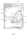
- Figure 2 is a display view of a navigational chart in accordance with one implementation of the present disclosure
- Figure 3 is a flow diagram of a method of facilitating the use of a navigational chart in accordance with one implementation of the present disclosure
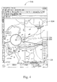
- Figure 4 is a display view of a navigational chart in accordance with one implementation of the present disclosure.
- Figure 5 is a display view of a navigational chart in accordance with one implementation of the present disclosure.
- the disclosure is directed to a method of facilitating the use of a navigational chart.
- the method may be performed by a computer including a display and a rotary input device, e.g. , a mouse having a mouse wheel.
- a computer including a display and a rotary input device, e.g. , a mouse having a mouse wheel.
- a rotary input device e.g. , a mouse having a mouse wheel.
- a navigational chart system in accordance with one implementation of the present disclosure is indicated generally in Figure 1 by reference number 20.
- the system 20 includes a computer 28 including a processor and memory, a display 36, and a keyboard 42.
- the computer 28 is a laptop computer, in various implementations the computer 28 may be installed in a mobile platform, e.g. , in the flight deck of an aircraft.
- the computer 28 may have access to information from various information source(s). For example, during aircraft flight, the computer 28 may have access to information from a Global Positioning System (GPS) 50 describing a current position of the aircraft.
- GPS Global Positioning System
- the computer 28 includes rotary input device, e.g. , a mouse 56 having a mouse wheel 60.
- the wheel 60 may be scrolled in either of two directions by a user. Specifically and as known in the art, the user may use a finger to rotate the wheel 60 toward or away from himself/herself. Additionally or alternatively, the wheel 60 may be depressed by the user.
- a rotary input device may be a thumb roller on the control yoke of an aircraft.
- a rotary input device may be a roller included in an electronic flight bag (EFB) computer. Accordingly, references to rotation and/or depression of a mouse wheel should be construed to include activation of other or additional features available in a user-operable device to provide the same or similar functionality as set forth in this disclosure.
- EFB electronic flight bag
- the computer 28 may provide a navigational chart on the display 36 for viewing by the user, e.g. , a pilot or other flight crew member on board an aircraft. Additionally or alternatively, the system 20 may be used apart from any mobile platform, e.g. , by a flight crew member on the ground to plan a navigational route.
- the user may activate various controls, including but not limited to the mouse 56, to cause the computer 28 to pan the view in various ways.
- various controls including but not limited to the mouse 56
- the user may cause different areas of a chart to be displayed.
- the user may rotate the mouse wheel 60 in one of two directions or may depress the mouse wheel.
- the computer 28 detects movement of the mouse wheel 60.
- the computer 28 uses one or more geographical locations, as further described below, to identify one or more points on the chart.
- the computer 28 pans the view in the display 36 to center in the view at least one of the identified points.
- FIG 2 a display view 100 of a navigational chart 104.
- the chart 104 is stored in or is otherwise available to the computer 28.
- the chart 104 includes coordinate information describing a geographical area, e.g. , over which an aircraft is anticipated to fly.
- the view 100 shows, e.g. , topographical information 110 and a river 116.
- Geographical information describing other chart features and landmarks, including but not limited to airports, is included in the chart 104 and may be shown as the view is panned in various directions as controlled by the user.
- the user may use the system 20 to plan and/or modify one or more navigation routes. For example, in the view 100 is shown part of a route 120 which is overlaid onto the chart 104.
- a navigation route is defined by a plurality of waypoints, including but not necessarily limited to a starting point and a destination point, designated by the user.
- Each waypoint in a route can be identified and referred to by its geographic coordinates, which may be used by the system 20, e.g. , in overlaying the waypoints and route onto a chart.
- a waypoint 128 is shown in the view 100.
- the view 100 is centered approximately about a route point 140.
- FIG. 2 One implementation of a computer-performed method of facilitating the use of a navigational chart is indicated generally in Figure 3 by reference number 200.
- the method 200 shall be described with reference to the view 100 shown in Figure 2 and with reference to a subsequent view indicated generally in Figure 4 by reference number 300.
- the computer 28 monitors for and detects movement of the mouse wheel 60 by the user. When wheel movement is detected, in step 216 it is determined whether the wheel 60 is being rotated toward the user. If yes, then in step 222 the chart view 100 is panned, in accordance with the wheel movement, so that one or more points further along the route 120 become centered in the view.
- the waypoint 128 is shifted leftward and the view 300 is centered on a point 308 further along the route 120, i.e., closer to the route destination (not shown) than the point 140 previously centered in the view 100.
- the system 20 may continue to pan the view for as long as the mouse wheel rotational input is detected.
- the system 20 may refer to one or more route points between two waypoints to determine, e.g. , direction(s) and/or distance(s) in which to pan a view.
- the system 20 uses coordinates based on the geographical locations of the waypoints. Such coordinates may be expressed, for example, as geographic coordinates and/or in terms relative to the two waypoints.
- step 216 If in step 216 no rotation of the wheel 60 toward the user is detected, then it is determined in step 228 whether the wheel 60 is being rotated away from the user. If yes, then in step 234 the chart view is panned, in accordance with the wheel movement, so that one or more preceding points along the route 120, i.e., points closer to the beginning (not shown) of the route 120, become centered in the view.
- the disclosure is not limited to implementation in a “North Up” mode of operation.
- the disclosure may be implemented in connection with various display orientations, for example, in connection with a "Heading Up” mode, wherein a direction of travel is oriented to a top of the display 36. It should be noted that in some implementations of the disclosure in a "Heading Up” mode, a chart may be rotated in various directions as a given route takes turns in various directions.
- step 240 it is determined whether the mouse wheel 60 is depressed by the user during flight. If yes, then in step 246 the system 20 uses location information from the GPS system 50 to overlay a current location of the aircraft onto the chart 104 and to center the aircraft location in the chart view.
- An exemplary view displaying an aircraft current location is indicated generally in Figure 5 by reference number 400.
- An overlay icon 404 representing the aircraft current location is centered in the view 400 in accordance with step 246.
- step 252 the computer 28 determines which point on the route 120 is closest to the center of a view currently being displayed. The computer 28 then pans the view to center the closest route point in the view. Thus the user may conveniently center the route 120 in the display 36.
- centering one or more points in a view includes moving one or more points toward and into a central portion of a view.
- a view “center” thus is not limited to a single point, but may also include a central area or band of the view. What area in a view might be defined as “central” may depend on a given implementation.
- a "central" portion of a view may be a band extending horizontally across the entire view and extending vertically from a horizontal centerline of the view to include, e.g ., ten percent of the total height of the view. Additionally or alternatively, in some implementations a "central" portion could extend vertically or diagonally across a view.
- a "central" portion could be, e.g ., a central rectangle, square, circle or other shape having dimensions dependent on a given implementation.
- a "central" portion could be defined and/or adjusted with reference to particular geographic and/or other features in a chart.
- the system 20 may make one or more of the foregoing mouse wheel functions available to the user when part of a route is displayed within a predefined area of a chart view.
- the system 20 allows the mouse wheel 60 to be activated by the user as described above when part of a route is displayed within a central portion, e.g. , a central band of a selected width, e.g. , twenty percent, of a current view.
- Implementations of the foregoing methods make it possible for a pilot or other user to easily follow along a planned route when previewing the route within a charting application.
- An easy, intuitive way to follow a route is provided that requires far less user effort than would be the case where a charting application requires a user to click on arrows on the side of a display and/or drag a display.
Landscapes
- Engineering & Computer Science (AREA)
- Radar, Positioning & Navigation (AREA)
- Remote Sensing (AREA)
- Aviation & Aerospace Engineering (AREA)
- Physics & Mathematics (AREA)
- General Physics & Mathematics (AREA)
- Navigation (AREA)
- User Interface Of Digital Computer (AREA)
- Displays For Variable Information Using Movable Means (AREA)
Abstract
Description
- The present disclosure relates generally to navigational charting and, more particularly (but not exclusively) to navigational charting implemented using a computer and a rotary input device such as a mouse wheel.
- The statements in this section merely provide background information related to the present disclosure and may not constitute prior art.
- Computer-implemented navigational charting applications are commonly used by aircraft flight crews to gather flight information and to plan flights. During flight an aircraft pilot may refer to an electronic flight box (EFB) to view a chart displaying a route to be followed by the aircraft. Where a charting application is capable of displaying one or more routes, a user of the application typically wants to examine those chart sections that display a route being planned and/or followed.
- The present disclosure, in one implementation, is directed to a method of facilitating the use of a navigational chart. The invention is set out in the independent claim. Preferred or optional features are set out in the dependent claims. The method is performed by a computer including a display. The computer further includes a rotary input device. A view of the navigational chart is provided on the display. Movement of the rotary input device is detected. In response to the movement, the computer uses one or more geographical locations to identify one or more points on the chart, and pans the view in the display to center in the view at least one of the one or more points.
- In another implementation, the disclosure is directed to a method of facilitating the use of a navigational chart. The method is performed by a computer including a display, the computer further including a rotary input device. The method includes providing a view of the navigational chart on the display and detecting movement of the rotary input device. Based on the movement, the computer identifies one or more points of a route defined relative to the chart and pans the view in the display to center in the view at least one of the one or more identified route points.
- In yet another implementation, the disclosure is directed to a navigational chart system including a computer having a display and a rotary input device. The system is configured to provide a view of a navigational chart on the display and detect movement of the rotary input device. In response to the movement, the system uses one or more geographical locations to identify one or more points on the chart and pan the view in the display to center in the view at least one of the one or more points.
- Further areas of applicability will become apparent from the description provided herein. It should be understood that the description and specific examples are intended for purposes of illustration only and are not intended to limit the scope of the present disclosure.
- The drawings described herein are for illustration purposes only and are not intended to limit the scope of the present disclosure in any way.
- Figure 1 is a diagram of a navigational chart system in accordance with one implementation of the present disclosure;
- Figure 2 is a display view of a navigational chart in accordance with one implementation of the present disclosure;
- Figure 3 is a flow diagram of a method of facilitating the use of a navigational chart in accordance with one implementation of the present disclosure;
- Figure 4 is a display view of a navigational chart in accordance with one implementation of the present disclosure; and
- Figure 5 is a display view of a navigational chart in accordance with one implementation of the present disclosure.
- The following description is merely exemplary in nature and is not intended to limit the present disclosure, application, or uses.
- In some implementations, the disclosure is directed to a method of facilitating the use of a navigational chart. The method may be performed by a computer including a display and a rotary input device, e.g., a mouse having a mouse wheel. Although various implementations of the invention are described with reference to the use of navigational charts in relation to aircraft, the invention is not so limited. Implementations also are contemplated in connection with other types of mobile platforms, including but not limited to boats, ships, trucks, automobiles and/or other vehicles. More generally, the disclosure could be implemented in various charting applications in which it may be desirable, e.g., to facilitate the display of points along a navigation route that is being planned, displayed and/or followed.
- A navigational chart system in accordance with one implementation of the present disclosure is indicated generally in Figure 1 by
reference number 20. Thesystem 20 includes acomputer 28 including a processor and memory, adisplay 36, and akeyboard 42. Although in the present implementation thecomputer 28 is a laptop computer, in various implementations thecomputer 28 may be installed in a mobile platform, e.g., in the flight deck of an aircraft. In some implementations thecomputer 28 may have access to information from various information source(s). For example, during aircraft flight, thecomputer 28 may have access to information from a Global Positioning System (GPS) 50 describing a current position of the aircraft. - The
computer 28 includes rotary input device, e.g., amouse 56 having amouse wheel 60. Thewheel 60 may be scrolled in either of two directions by a user. Specifically and as known in the art, the user may use a finger to rotate thewheel 60 toward or away from himself/herself. Additionally or alternatively, thewheel 60 may be depressed by the user. It should be noted that although various implementations of the disclosure are described with reference to a mouse and mouse wheel, it is contemplated that other or additional rotary input devices could be used. For example, in some implementations a rotary input device may be a thumb roller on the control yoke of an aircraft. In various implementations, a rotary input device may be a roller included in an electronic flight bag (EFB) computer. Accordingly, references to rotation and/or depression of a mouse wheel should be construed to include activation of other or additional features available in a user-operable device to provide the same or similar functionality as set forth in this disclosure. - When a user uses the
system 20 to perform a charting application, thecomputer 28 may provide a navigational chart on thedisplay 36 for viewing by the user, e.g., a pilot or other flight crew member on board an aircraft. Additionally or alternatively, thesystem 20 may be used apart from any mobile platform, e.g., by a flight crew member on the ground to plan a navigational route. - When the
computer 28 provides a navigational chart view on thedisplay 36, the user may activate various controls, including but not limited to themouse 56, to cause thecomputer 28 to pan the view in various ways. Thus the user may cause different areas of a chart to be displayed. As previously mentioned, the user may rotate themouse wheel 60 in one of two directions or may depress the mouse wheel. Thecomputer 28 detects movement of themouse wheel 60. In various implementations of the disclosure, in response to the mouse wheel movement, thecomputer 28 uses one or more geographical locations, as further described below, to identify one or more points on the chart. Thecomputer 28 pans the view in thedisplay 36 to center in the view at least one of the identified points. - In Figure 2 is shown a
display view 100 of anavigational chart 104. Thechart 104 is stored in or is otherwise available to thecomputer 28. Thechart 104 includes coordinate information describing a geographical area, e.g., over which an aircraft is anticipated to fly. Theview 100 shows, e.g.,topographical information 110 and ariver 116. Geographical information describing other chart features and landmarks, including but not limited to airports, is included in thechart 104 and may be shown as the view is panned in various directions as controlled by the user. As known in the art, the user may use thesystem 20 to plan and/or modify one or more navigation routes. For example, in theview 100 is shown part of aroute 120 which is overlaid onto thechart 104. In thesystem 20, a navigation route is defined by a plurality of waypoints, including but not necessarily limited to a starting point and a destination point, designated by the user. Each waypoint in a route can be identified and referred to by its geographic coordinates, which may be used by thesystem 20, e.g., in overlaying the waypoints and route onto a chart. In theview 100, awaypoint 128 is shown. Theview 100 is centered approximately about aroute point 140. - One implementation of a computer-performed method of facilitating the use of a navigational chart is indicated generally in Figure 3 by
reference number 200. Themethod 200 shall be described with reference to theview 100 shown in Figure 2 and with reference to a subsequent view indicated generally in Figure 4 byreference number 300. Instep 208 thecomputer 28 monitors for and detects movement of themouse wheel 60 by the user. When wheel movement is detected, instep 216 it is determined whether thewheel 60 is being rotated toward the user. If yes, then instep 222 thechart view 100 is panned, in accordance with the wheel movement, so that one or more points further along theroute 120 become centered in the view. For example, as shown in theview 300, thewaypoint 128 is shifted leftward and theview 300 is centered on apoint 308 further along theroute 120, i.e., closer to the route destination (not shown) than thepoint 140 previously centered in theview 100. Thesystem 20 may continue to pan the view for as long as the mouse wheel rotational input is detected. - In one implementation the
system 20 may refer to one or more route points between two waypoints to determine, e.g., direction(s) and/or distance(s) in which to pan a view. To refer to such route points, thesystem 20 uses coordinates based on the geographical locations of the waypoints. Such coordinates may be expressed, for example, as geographic coordinates and/or in terms relative to the two waypoints. - If in
step 216 no rotation of thewheel 60 toward the user is detected, then it is determined instep 228 whether thewheel 60 is being rotated away from the user. If yes, then instep 234 the chart view is panned, in accordance with the wheel movement, so that one or more preceding points along theroute 120, i.e., points closer to the beginning (not shown) of theroute 120, become centered in the view. - Although the
views display 36. It should be noted that in some implementations of the disclosure in a "Heading Up" mode, a chart may be rotated in various directions as a given route takes turns in various directions. - In
step 240 it is determined whether themouse wheel 60 is depressed by the user during flight. If yes, then instep 246 thesystem 20 uses location information from theGPS system 50 to overlay a current location of the aircraft onto thechart 104 and to center the aircraft location in the chart view. An exemplary view displaying an aircraft current location is indicated generally in Figure 5 byreference number 400. Anoverlay icon 404 representing the aircraft current location is centered in theview 400 in accordance withstep 246. - Referring again to Figure 3, if it is determined in
step 240 that thewheel 60 is depressed and that thesystem 20 is not being used during flight, then instep 252 thecomputer 28 determines which point on theroute 120 is closest to the center of a view currently being displayed. Thecomputer 28 then pans the view to center the closest route point in the view. Thus the user may conveniently center theroute 120 in thedisplay 36. - It should be noted that unless stated otherwise, centering one or more points in a view includes moving one or more points toward and into a central portion of a view. A view "center" thus is not limited to a single point, but may also include a central area or band of the view. What area in a view might be defined as "central" may depend on a given implementation. In some implementations, a "central" portion of a view may be a band extending horizontally across the entire view and extending vertically from a horizontal centerline of the view to include, e.g., ten percent of the total height of the view. Additionally or alternatively, in some implementations a "central" portion could extend vertically or diagonally across a view. It also is contemplated that a "central" portion could be, e.g., a central rectangle, square, circle or other shape having dimensions dependent on a given implementation. In some implementations, a "central" portion could be defined and/or adjusted with reference to particular geographic and/or other features in a chart.
- It can be advantageous to limit the use of the foregoing mouse wheel functions to situations, e.g., in which it is desired to display a route in the center of a view. Thus, in various implementations, the
system 20 may make one or more of the foregoing mouse wheel functions available to the user when part of a route is displayed within a predefined area of a chart view. For example, in one implementation and referring to Figure 1, thesystem 20 allows themouse wheel 60 to be activated by the user as described above when part of a route is displayed within a central portion, e.g., a central band of a selected width, e.g., twenty percent, of a current view. - Implementations of the foregoing methods make it possible for a pilot or other user to easily follow along a planned route when previewing the route within a charting application. An easy, intuitive way to follow a route is provided that requires far less user effort than would be the case where a charting application requires a user to click on arrows on the side of a display and/or drag a display.
- While various embodiments have been described, those skilled in the art will recognize modifications or variations which might be made without departing from the present disclosure. The examples illustrate the various embodiments and are not intended to limit the present disclosure. Therefore, the description and claims should be interpreted liberally with only such limitation as is necessary in view of the pertinent prior art.
Claims (9)
- A method of facilitating the use of a navigational chart, the method performed by a computer including a display, the computer further including a rotary input device, the method comprising:providing a view of the navigational chart on the display;detecting movement of the rotary input device; andin response to the movement:using one or more geographical locations to identify one or more points on the chart; andpanning the view in the display to center in the view at least one of the one or more points.
- The method of claim 1, wherein the one or more points include one or more points of a route defined relative to the chart.
- The method of claim 2, further comprising panning the view in a direction relative to the route based on a detected direction of rotation of the rotary input device.
- The method of claim 2, further comprising panning the view to center a route point following a route point previously centered in the view, the panning performed in response to a first direction of rotary input device rotation.
- The method of claim 2, further comprising panning the view to center a route point preceding a route point previously centered in the view, the panning performed in response to a second direction of rotary input device rotation.
- The method of claim 2, wherein the one or more geographical locations include at least one waypoint included in the route.
- The method of claim 2, wherein depression of the rotary input device is detected, the one or more points on the chart including a route point nearest a center of the view, the panning performed to center the nearest route point.
- The method of claim 1, wherein the one or more geographical locations include a current geographical location of a mobile platform on which the computer is located, the panning performed to center a point on the chart representing the current geographical location of the mobile platform.
- A navigational chart system comprising a computer including a display and a rotary input device, the system configured to:Perform the method of any of claims 1 through 8.
Applications Claiming Priority (1)
| Application Number | Priority Date | Filing Date | Title |
|---|---|---|---|
| US11/598,534 US7756629B2 (en) | 2006-11-13 | 2006-11-13 | Using a rotary input device to facilitate navigational charting |
Publications (3)
| Publication Number | Publication Date |
|---|---|
| EP1921536A2 true EP1921536A2 (en) | 2008-05-14 |
| EP1921536A3 EP1921536A3 (en) | 2012-08-29 |
| EP1921536B1 EP1921536B1 (en) | 2018-09-12 |
Family
ID=39203291
Family Applications (1)
| Application Number | Title | Priority Date | Filing Date |
|---|---|---|---|
| EP07120513.2A Active EP1921536B1 (en) | 2006-11-13 | 2007-11-12 | Using a rotary input device to facilitate the use of a navigational chart |
Country Status (2)
| Country | Link |
|---|---|
| US (1) | US7756629B2 (en) |
| EP (1) | EP1921536B1 (en) |
Families Citing this family (4)
| Publication number | Priority date | Publication date | Assignee | Title |
|---|---|---|---|---|
| US9146119B2 (en) * | 2009-06-05 | 2015-09-29 | Microsoft Technology Licensing, Llc | Scrubbing variable content paths |
| US8515658B1 (en) * | 2009-07-06 | 2013-08-20 | The Boeing Company | Managing navigational chart presentation |
| US10041802B1 (en) * | 2011-09-28 | 2018-08-07 | The Boeing Company | Methods and systems for depicting own ship |
| FR3112005B1 (en) * | 2020-06-30 | 2023-03-10 | Thales Sa | Aeronautical map display management system and method |
Citations (3)
| Publication number | Priority date | Publication date | Assignee | Title |
|---|---|---|---|---|
| US6112141A (en) | 1997-10-15 | 2000-08-29 | Dassault Aviation | Apparatus and method for graphically oriented aircraft display and control |
| EP1246049A2 (en) | 2001-03-27 | 2002-10-02 | Sony Corporation | Display control method for information processing device |
| US20040204833A1 (en) | 2002-08-13 | 2004-10-14 | Tatsuo Yokota | Display method and apparatus for navigation system |
Family Cites Families (1)
| Publication number | Priority date | Publication date | Assignee | Title |
|---|---|---|---|---|
| US20070268246A1 (en) * | 2006-05-17 | 2007-11-22 | Edward Craig Hyatt | Electronic equipment with screen pan and zoom functions using motion |
-
2006
- 2006-11-13 US US11/598,534 patent/US7756629B2/en active Active
-
2007
- 2007-11-12 EP EP07120513.2A patent/EP1921536B1/en active Active
Patent Citations (3)
| Publication number | Priority date | Publication date | Assignee | Title |
|---|---|---|---|---|
| US6112141A (en) | 1997-10-15 | 2000-08-29 | Dassault Aviation | Apparatus and method for graphically oriented aircraft display and control |
| EP1246049A2 (en) | 2001-03-27 | 2002-10-02 | Sony Corporation | Display control method for information processing device |
| US20040204833A1 (en) | 2002-08-13 | 2004-10-14 | Tatsuo Yokota | Display method and apparatus for navigation system |
Also Published As
| Publication number | Publication date |
|---|---|
| EP1921536A3 (en) | 2012-08-29 |
| EP1921536B1 (en) | 2018-09-12 |
| US20080114537A1 (en) | 2008-05-15 |
| US7756629B2 (en) | 2010-07-13 |
Similar Documents
| Publication | Publication Date | Title |
|---|---|---|
| US8645056B2 (en) | System and method for electronic moving map and aeronautical context display | |
| US6389355B1 (en) | Methods and apparatus for graphical display and editing of flight plans | |
| US8234066B2 (en) | System and method for terminal charts, airport maps and aeronautical context display | |
| US10304344B2 (en) | Methods and systems for safe landing at a diversion airport | |
| US7737951B2 (en) | Navigation device with touch screen | |
| EP3125213B1 (en) | Onboard aircraft systems and methods to identify moving landing platforms | |
| EP2180457A1 (en) | Method and apparatus for displaying prioritized photo realistic features on a synthetic vision system | |
| US20090063032A1 (en) | Methods, systems, and apparatus for routing a vehicle to avoid an adverse condition | |
| US7961116B2 (en) | Apparatus and method of displaying an aircraft's position | |
| US9842567B2 (en) | Electronic chart display device and method of displaying information relating to electronic chart | |
| US9734727B2 (en) | Aircraft systems and methods to display moving landing platforms | |
| CA3008986A1 (en) | Automatic flight control systems and methods | |
| US10600328B2 (en) | Aircraft systems and methods for approach stabilization | |
| EP1972897B1 (en) | System and method for indicating the field of view of a three dimensional display on a two dimensional display | |
| EP1921536A2 (en) | Using a rotary input device to facilitate navigational charting | |
| CN104973257B (en) | System and method for displaying optimized native position on a navigation display | |
| US20090322753A1 (en) | Method of automatically selecting degree of zoom when switching from one map to another | |
| WO2011024189A2 (en) | System and method for computing flight time from an equi- distance point to a reference point | |
| HK1116275A (en) | Using a rotary input device to facilitate the use of a navigational chart | |
| US8170789B2 (en) | Method for providing search area coverage information | |
| HK1116275B (en) | Using a rotary input device to facilitate the use of a navigational chart | |
| EP4000982B1 (en) | Systems and methods of augmented reality visualization based on sensor data | |
| JP5521717B2 (en) | Image display method |
Legal Events
| Date | Code | Title | Description |
|---|---|---|---|
| PUAI | Public reference made under article 153(3) epc to a published international application that has entered the european phase |
Free format text: ORIGINAL CODE: 0009012 |
|
| 17P | Request for examination filed |
Effective date: 20071113 |
|
| AK | Designated contracting states |
Kind code of ref document: A2 Designated state(s): AT BE BG CH CY CZ DE DK EE ES FI FR GB GR HU IE IS IT LI LT LU LV MC MT NL PL PT RO SE SI SK TR |
|
| AX | Request for extension of the european patent |
Extension state: AL BA HR MK RS |
|
| REG | Reference to a national code |
Ref country code: HK Ref legal event code: DE Ref document number: 1116275 Country of ref document: HK |
|
| PUAL | Search report despatched |
Free format text: ORIGINAL CODE: 0009013 |
|
| AK | Designated contracting states |
Kind code of ref document: A3 Designated state(s): AT BE BG CH CY CZ DE DK EE ES FI FR GB GR HU IE IS IT LI LT LU LV MC MT NL PL PT RO SE SI SK TR |
|
| AX | Request for extension of the european patent |
Extension state: AL BA HR MK RS |
|
| RIC1 | Information provided on ipc code assigned before grant |
Ipc: G06F 3/033 20060101AFI20120720BHEP Ipc: G01C 23/00 20060101ALI20120720BHEP Ipc: G06G 1/00 20060101ALI20120720BHEP |
|
| AKX | Designation fees paid |
Designated state(s): AT BE BG CH CY CZ DE DK EE ES FI FR GB GR HU IE IS IT LI LT LU LV MC MT NL PL PT RO SE SI SK TR |
|
| 17Q | First examination report despatched |
Effective date: 20170323 |
|
| RIC1 | Information provided on ipc code assigned before grant |
Ipc: G06F 3/033 20130101AFI20171003BHEP Ipc: G01C 21/20 20060101ALI20171003BHEP Ipc: G01C 23/00 20060101ALI20171003BHEP Ipc: G06G 1/00 20060101ALI20171003BHEP |
|
| GRAP | Despatch of communication of intention to grant a patent |
Free format text: ORIGINAL CODE: EPIDOSNIGR1 |
|
| INTG | Intention to grant announced |
Effective date: 20180123 |
|
| GRAS | Grant fee paid |
Free format text: ORIGINAL CODE: EPIDOSNIGR3 |
|
| GRAJ | Information related to disapproval of communication of intention to grant by the applicant or resumption of examination proceedings by the epo deleted |
Free format text: ORIGINAL CODE: EPIDOSDIGR1 |
|
| GRAL | Information related to payment of fee for publishing/printing deleted |
Free format text: ORIGINAL CODE: EPIDOSDIGR3 |
|
| INTC | Intention to grant announced (deleted) | ||
| GRAP | Despatch of communication of intention to grant a patent |
Free format text: ORIGINAL CODE: EPIDOSNIGR1 |
|
| GRAA | (expected) grant |
Free format text: ORIGINAL CODE: 0009210 |
|
| INTG | Intention to grant announced |
Effective date: 20180724 |
|
| AK | Designated contracting states |
Kind code of ref document: B1 Designated state(s): AT BE BG CH CY CZ DE DK EE ES FI FR GB GR HU IE IS IT LI LT LU LV MC MT NL PL PT RO SE SI SK TR |
|
| REG | Reference to a national code |
Ref country code: GB Ref legal event code: FG4D |
|
| REG | Reference to a national code |
Ref country code: CH Ref legal event code: EP |
|
| REG | Reference to a national code |
Ref country code: IE Ref legal event code: FG4D |
|
| REG | Reference to a national code |
Ref country code: DE Ref legal event code: R096 Ref document number: 602007056103 Country of ref document: DE |
|
| REG | Reference to a national code |
Ref country code: AT Ref legal event code: REF Ref document number: 1041368 Country of ref document: AT Kind code of ref document: T Effective date: 20181015 |
|
| REG | Reference to a national code |
Ref country code: NL Ref legal event code: MP Effective date: 20180912 |
|
| REG | Reference to a national code |
Ref country code: LT Ref legal event code: MG4D |
|
| PG25 | Lapsed in a contracting state [announced via postgrant information from national office to epo] |
Ref country code: SE Free format text: LAPSE BECAUSE OF FAILURE TO SUBMIT A TRANSLATION OF THE DESCRIPTION OR TO PAY THE FEE WITHIN THE PRESCRIBED TIME-LIMIT Effective date: 20180912 Ref country code: BG Free format text: LAPSE BECAUSE OF FAILURE TO SUBMIT A TRANSLATION OF THE DESCRIPTION OR TO PAY THE FEE WITHIN THE PRESCRIBED TIME-LIMIT Effective date: 20181212 Ref country code: GR Free format text: LAPSE BECAUSE OF FAILURE TO SUBMIT A TRANSLATION OF THE DESCRIPTION OR TO PAY THE FEE WITHIN THE PRESCRIBED TIME-LIMIT Effective date: 20181213 Ref country code: FI Free format text: LAPSE BECAUSE OF FAILURE TO SUBMIT A TRANSLATION OF THE DESCRIPTION OR TO PAY THE FEE WITHIN THE PRESCRIBED TIME-LIMIT Effective date: 20180912 Ref country code: LT Free format text: LAPSE BECAUSE OF FAILURE TO SUBMIT A TRANSLATION OF THE DESCRIPTION OR TO PAY THE FEE WITHIN THE PRESCRIBED TIME-LIMIT Effective date: 20180912 |
|
| PG25 | Lapsed in a contracting state [announced via postgrant information from national office to epo] |
Ref country code: LV Free format text: LAPSE BECAUSE OF FAILURE TO SUBMIT A TRANSLATION OF THE DESCRIPTION OR TO PAY THE FEE WITHIN THE PRESCRIBED TIME-LIMIT Effective date: 20180912 Ref country code: ES Free format text: LAPSE BECAUSE OF FAILURE TO SUBMIT A TRANSLATION OF THE DESCRIPTION OR TO PAY THE FEE WITHIN THE PRESCRIBED TIME-LIMIT Effective date: 20180912 |
|
| REG | Reference to a national code |
Ref country code: AT Ref legal event code: MK05 Ref document number: 1041368 Country of ref document: AT Kind code of ref document: T Effective date: 20180912 |
|
| PG25 | Lapsed in a contracting state [announced via postgrant information from national office to epo] |
Ref country code: EE Free format text: LAPSE BECAUSE OF FAILURE TO SUBMIT A TRANSLATION OF THE DESCRIPTION OR TO PAY THE FEE WITHIN THE PRESCRIBED TIME-LIMIT Effective date: 20180912 Ref country code: PL Free format text: LAPSE BECAUSE OF FAILURE TO SUBMIT A TRANSLATION OF THE DESCRIPTION OR TO PAY THE FEE WITHIN THE PRESCRIBED TIME-LIMIT Effective date: 20180912 Ref country code: NL Free format text: LAPSE BECAUSE OF FAILURE TO SUBMIT A TRANSLATION OF THE DESCRIPTION OR TO PAY THE FEE WITHIN THE PRESCRIBED TIME-LIMIT Effective date: 20180912 Ref country code: IS Free format text: LAPSE BECAUSE OF FAILURE TO SUBMIT A TRANSLATION OF THE DESCRIPTION OR TO PAY THE FEE WITHIN THE PRESCRIBED TIME-LIMIT Effective date: 20190112 Ref country code: CZ Free format text: LAPSE BECAUSE OF FAILURE TO SUBMIT A TRANSLATION OF THE DESCRIPTION OR TO PAY THE FEE WITHIN THE PRESCRIBED TIME-LIMIT Effective date: 20180912 Ref country code: IT Free format text: LAPSE BECAUSE OF FAILURE TO SUBMIT A TRANSLATION OF THE DESCRIPTION OR TO PAY THE FEE WITHIN THE PRESCRIBED TIME-LIMIT Effective date: 20180912 Ref country code: RO Free format text: LAPSE BECAUSE OF FAILURE TO SUBMIT A TRANSLATION OF THE DESCRIPTION OR TO PAY THE FEE WITHIN THE PRESCRIBED TIME-LIMIT Effective date: 20180912 Ref country code: AT Free format text: LAPSE BECAUSE OF FAILURE TO SUBMIT A TRANSLATION OF THE DESCRIPTION OR TO PAY THE FEE WITHIN THE PRESCRIBED TIME-LIMIT Effective date: 20180912 |
|
| PG25 | Lapsed in a contracting state [announced via postgrant information from national office to epo] |
Ref country code: SK Free format text: LAPSE BECAUSE OF FAILURE TO SUBMIT A TRANSLATION OF THE DESCRIPTION OR TO PAY THE FEE WITHIN THE PRESCRIBED TIME-LIMIT Effective date: 20180912 Ref country code: PT Free format text: LAPSE BECAUSE OF FAILURE TO SUBMIT A TRANSLATION OF THE DESCRIPTION OR TO PAY THE FEE WITHIN THE PRESCRIBED TIME-LIMIT Effective date: 20190112 |
|
| REG | Reference to a national code |
Ref country code: DE Ref legal event code: R097 Ref document number: 602007056103 Country of ref document: DE |
|
| REG | Reference to a national code |
Ref country code: CH Ref legal event code: PL |
|
| PLBE | No opposition filed within time limit |
Free format text: ORIGINAL CODE: 0009261 |
|
| STAA | Information on the status of an ep patent application or granted ep patent |
Free format text: STATUS: NO OPPOSITION FILED WITHIN TIME LIMIT |
|
| PG25 | Lapsed in a contracting state [announced via postgrant information from national office to epo] |
Ref country code: DK Free format text: LAPSE BECAUSE OF FAILURE TO SUBMIT A TRANSLATION OF THE DESCRIPTION OR TO PAY THE FEE WITHIN THE PRESCRIBED TIME-LIMIT Effective date: 20180912 Ref country code: LU Free format text: LAPSE BECAUSE OF NON-PAYMENT OF DUE FEES Effective date: 20181112 Ref country code: MC Free format text: LAPSE BECAUSE OF FAILURE TO SUBMIT A TRANSLATION OF THE DESCRIPTION OR TO PAY THE FEE WITHIN THE PRESCRIBED TIME-LIMIT Effective date: 20180912 |
|
| REG | Reference to a national code |
Ref country code: BE Ref legal event code: MM Effective date: 20181130 |
|
| 26N | No opposition filed |
Effective date: 20190613 |
|
| REG | Reference to a national code |
Ref country code: IE Ref legal event code: MM4A |
|
| PG25 | Lapsed in a contracting state [announced via postgrant information from national office to epo] |
Ref country code: LI Free format text: LAPSE BECAUSE OF NON-PAYMENT OF DUE FEES Effective date: 20181130 Ref country code: SI Free format text: LAPSE BECAUSE OF FAILURE TO SUBMIT A TRANSLATION OF THE DESCRIPTION OR TO PAY THE FEE WITHIN THE PRESCRIBED TIME-LIMIT Effective date: 20180912 Ref country code: CH Free format text: LAPSE BECAUSE OF NON-PAYMENT OF DUE FEES Effective date: 20181130 |
|
| PG25 | Lapsed in a contracting state [announced via postgrant information from national office to epo] |
Ref country code: IE Free format text: LAPSE BECAUSE OF NON-PAYMENT OF DUE FEES Effective date: 20181112 |
|
| PG25 | Lapsed in a contracting state [announced via postgrant information from national office to epo] |
Ref country code: BE Free format text: LAPSE BECAUSE OF NON-PAYMENT OF DUE FEES Effective date: 20181130 |
|
| PG25 | Lapsed in a contracting state [announced via postgrant information from national office to epo] |
Ref country code: MT Free format text: LAPSE BECAUSE OF NON-PAYMENT OF DUE FEES Effective date: 20181112 |
|
| PG25 | Lapsed in a contracting state [announced via postgrant information from national office to epo] |
Ref country code: TR Free format text: LAPSE BECAUSE OF FAILURE TO SUBMIT A TRANSLATION OF THE DESCRIPTION OR TO PAY THE FEE WITHIN THE PRESCRIBED TIME-LIMIT Effective date: 20180912 |
|
| PG25 | Lapsed in a contracting state [announced via postgrant information from national office to epo] |
Ref country code: CY Free format text: LAPSE BECAUSE OF FAILURE TO SUBMIT A TRANSLATION OF THE DESCRIPTION OR TO PAY THE FEE WITHIN THE PRESCRIBED TIME-LIMIT Effective date: 20180912 Ref country code: HU Free format text: LAPSE BECAUSE OF FAILURE TO SUBMIT A TRANSLATION OF THE DESCRIPTION OR TO PAY THE FEE WITHIN THE PRESCRIBED TIME-LIMIT; INVALID AB INITIO Effective date: 20071112 |
|
| P01 | Opt-out of the competence of the unified patent court (upc) registered |
Effective date: 20230516 |
|
| PGFP | Annual fee paid to national office [announced via postgrant information from national office to epo] |
Ref country code: DE Payment date: 20251128 Year of fee payment: 19 |
|
| PGFP | Annual fee paid to national office [announced via postgrant information from national office to epo] |
Ref country code: GB Payment date: 20251223 Year of fee payment: 19 |
|
| PGFP | Annual fee paid to national office [announced via postgrant information from national office to epo] |
Ref country code: FR Payment date: 20251125 Year of fee payment: 19 |