EP1921481A2 - Light scanning unit and image forming apparatus using the same - Google Patents
Light scanning unit and image forming apparatus using the same Download PDFInfo
- Publication number
- EP1921481A2 EP1921481A2 EP07117331A EP07117331A EP1921481A2 EP 1921481 A2 EP1921481 A2 EP 1921481A2 EP 07117331 A EP07117331 A EP 07117331A EP 07117331 A EP07117331 A EP 07117331A EP 1921481 A2 EP1921481 A2 EP 1921481A2
- Authority
- EP
- European Patent Office
- Prior art keywords
- lens
- scanning unit
- light source
- sag
- light
- Prior art date
- Legal status (The legal status is an assumption and is not a legal conclusion. Google has not performed a legal analysis and makes no representation as to the accuracy of the status listed.)
- Granted
Links
Images







Classifications
-
- G—PHYSICS
- G02—OPTICS
- G02B—OPTICAL ELEMENTS, SYSTEMS OR APPARATUS
- G02B26/00—Optical devices or arrangements for the control of light using movable or deformable optical elements
- G02B26/08—Optical devices or arrangements for the control of light using movable or deformable optical elements for controlling the direction of light
- G02B26/10—Scanning systems
-
- G—PHYSICS
- G02—OPTICS
- G02B—OPTICAL ELEMENTS, SYSTEMS OR APPARATUS
- G02B26/00—Optical devices or arrangements for the control of light using movable or deformable optical elements
- G02B26/08—Optical devices or arrangements for the control of light using movable or deformable optical elements for controlling the direction of light
- G02B26/10—Scanning systems
- G02B26/12—Scanning systems using multifaceted mirrors
- G02B26/125—Details of the optical system between the polygonal mirror and the image plane
-
- G—PHYSICS
- G02—OPTICS
- G02B—OPTICAL ELEMENTS, SYSTEMS OR APPARATUS
- G02B13/00—Optical objectives specially designed for the purposes specified below
- G02B13/0005—Optical objectives specially designed for the purposes specified below having F-Theta characteristic
-
- G—PHYSICS
- G02—OPTICS
- G02B—OPTICAL ELEMENTS, SYSTEMS OR APPARATUS
- G02B27/00—Optical systems or apparatus not provided for by any of the groups G02B1/00 - G02B26/00, G02B30/00
- G02B27/0025—Optical systems or apparatus not provided for by any of the groups G02B1/00 - G02B26/00, G02B30/00 for optical correction, e.g. distorsion, aberration
- G02B27/0031—Optical systems or apparatus not provided for by any of the groups G02B1/00 - G02B26/00, G02B30/00 for optical correction, e.g. distorsion, aberration for scanning purposes
-
- H—ELECTRICITY
- H04—ELECTRIC COMMUNICATION TECHNIQUE
- H04N—PICTORIAL COMMUNICATION, e.g. TELEVISION
- H04N1/00—Scanning, transmission or reproduction of documents or the like, e.g. facsimile transmission; Details thereof
- H04N1/04—Scanning arrangements, i.e. arrangements for the displacement of active reading or reproducing elements relative to the original or reproducing medium, or vice versa
- H04N1/113—Scanning arrangements, i.e. arrangements for the displacement of active reading or reproducing elements relative to the original or reproducing medium, or vice versa using oscillating or rotating mirrors
- H04N1/1135—Scanning arrangements, i.e. arrangements for the displacement of active reading or reproducing elements relative to the original or reproducing medium, or vice versa using oscillating or rotating mirrors for the main-scan only
-
- H—ELECTRICITY
- H04—ELECTRIC COMMUNICATION TECHNIQUE
- H04N—PICTORIAL COMMUNICATION, e.g. TELEVISION
- H04N2201/00—Indexing scheme relating to scanning, transmission or reproduction of documents or the like, and to details thereof
- H04N2201/0077—Types of the still picture apparatus
- H04N2201/0082—Image hardcopy reproducer
Definitions
- the present invention relates to a light scanning unit that scans an incident beam to be deflected onto a photosensitive medium and to an image forming apparatus using the same. More particularly, the present invention relates to a light scanning unit that has a structure for enhancing its sensitivity to curvature of a scanning line at a scanning surface due to a placement error of an f- ⁇ lens and an image forming apparatus using the same.
- a light scanning unit is employed in image forming apparatuses such as laser beam printers, digital copiers, facsimile machines and multi-functional devices.
- a light scanning unit is used to deflect a laser beam irradiated from a light source and scan the laser beam in a main scanning direction of a photosensitive medium.
- An electrostatic latent image is formed on the exposed medium through scanning by the light scanning unit (referred to as "main scanning") and by the movement of the exposed medium (referred to as "sub-scanning").
- the light scanning unit is also required to decrease the curvature of a scanning line on the scanning surface, which is associated with a placement error of an optical system.
- the optical component usually has the shape of a lens in the main scanning direction, and its operation is influenced by whether light that has passed through a collimating lens is a parallel light or a converging light and by the number and location of f- ⁇ lenses.
- an average and a deviation of the sub-scanning magnification are important factors in determining the magnification by the number and the location of the f- ⁇ lenses and radii of curvature of an incident surface and an exit surface of the f- ⁇ lenses.
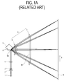
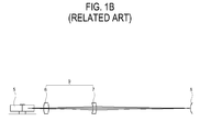
- FIG. 1A and FIG. 1B show a conventional light scanning unit arranged to scan a laser beam in a main scanning direction of an exposed photosensitive medium.
- the conventional light scanning unit comprises a light source 1 that generates and irradiates a beam, a beam deflector 5 that deflects an incident beam to scan the beam irradiated by the light source 1 onto an exposed medium 8, and an f- ⁇ lens 9 that corrects an error contained in the beam deflected by the beam deflector 5.
- the conventional light scanning unit may also include a diaphragm 2, a collimating lens 3 that collects the beam irradiated by the light source 1, via the diaphragm 2, to be a parallel beam, and a cylindrical lens 4 that shapes the beam.
- the diaphragm 2, collimating lens 3 and cylindrical lens 4 are installed in an optical path between the light source 1 and the beam deflector 5.
- the beam deflector 5 comprises a rotary polygonal mirror rotated by a driving source (not shown).
- the beam irradiated by the light source 1 changes its direction while it is reflected by the rotating beam deflector 5, thus determining a scanning direction. That is, if the rotary polygonal mirror rotates in a direction A, the incident beam is reflected by a reflecting surface 5a of the rotary polygonal mirror and scanned in a main scanning direction B onto a scanning surface of the exposed medium 8.
- the f- ⁇ lens 9 comprises two lenses, a first lens 6 and a second lens 7.
- the first lens 6 has a meniscus shape in its main scanning sectional view, and thus has a positive refractive power. If "fm" is a focal distance in the main scanning surface of the exposed medium 8 and d1 is a center thickness of the first lens 6, a condition of d1/fm ⁇ 0.06 is satisfied.
- the second lens 7 has a surface corresponding to the incident beam that is formed as a non-spherical surface or an oval surface without an inflection point, in a sub-scanning direction. If R is the radius of curvature on a beam axis in the main scanning surface sectional view of the surface corresponding to the incident beam, a condition of 2.5 ⁇
- the curvature of the scanning line can be minimized by lens placement and conditions mentioned above when there is a parallel eccentricity that corresponds to a movement of the f- ⁇ lens 9 in the sub-scanning direction.
- the conventional light scanning unit as described with reference to FIG. 1A and FIG. 1B is configured as an infinite optical system, where the beam that has passed through the collimating lens 3 is scanned parallel and two f- ⁇ lenses 9 are used to improve the sensitivity to curvature of a scanning line, there is a disadvantage in that a degree of freedom of the lens placement is decreased or limited. Accordingly, if a tandem type light scanning unit is symmetrically configured to center around the beam deflector, the degree of freedom of an optical placement is inevitably decreased.
- the present invention provides a light scanning unit and image forming apparatus, where a sensitivity to curvature of a scanning line at a scanning surface due to a placement error of an f- ⁇ lens is enhanced, a degree of freedom of an optical placement is increased by using a single f- ⁇ lens, productivity is increased by reducing the possibility of the occurrence of a placement error and a manufacturing costs are reduced.
- a light scanning unit is provided with a light source to generate and irradiate at least one beam corresponding to an image signal; a beam deflector to deflect and scan the beam irradiated by the light source; and an f- ⁇ lens to form an image from the beam deflected by the beam deflector onto a surface to be scanned, the f- ⁇ lens being provided as a single lens having a shape that satisfies the following equation (2): - 0.2 ⁇ SAG ⁇ 1 + SAG ⁇ 2 d 2 ⁇ 0.2
- SAG 1 is the Z value of the incident surface of the f- ⁇ lens
- SAG 2 is the Z value of the exit surface of the f- ⁇ lens based on an XYZ coordinate system in which a main scanning plane is an Y-Z plane and a sub-scanning plane is an X-Z plane
- d2 is a center thickness of the f- ⁇ lens.
- a ratio R1/R2 of a radius of curvature in a sub-scanning direction of the f- ⁇ lens satisfies the following equation (3): 0 ⁇ R ⁇ 1 / R ⁇ 2 ⁇ 3.2 where R1 is a radius of curvature of the incident surface and R2 is a radius of curvature of the exit surface.
- a sub-scanning magnification Ms_f ⁇ of the f- ⁇ lens satisfies the following equation (4): - 2.1 ⁇ Ms_f ⁇ ⁇ 0
- the light scanning unit further comprises a collimating lens that collects the beam irradiated by the light source, and a cylindrical lens that corrects the beam irradiated to the beam deflector, wherein the collimating lens and the cylindrical lens are provided in a beam path between the light source and the beam deflector.
- an overall magnification deviation ⁇ Ms_tot caused by the collimating lens, the cylindrical lens and the f- ⁇ lens satisfies the following equation(5): - 2.0 ⁇ ⁇ Ms_tot ⁇ 2.0 %
- the collimating lens is positioned so that the beam in the main scanning direction from the collimating lens to the f- ⁇ lens is not a parallel beam.
- an image forming apparatus comprising a photosensitive medium where an electrostatic latent image is formed; a light scanning unit to scan a beam onto the photosensitive medium to form the electrostatic latent image; a developing unit to form a toner image on the photosensitive medium; a transfer unit to transfer the toner image formed on the photosensitive medium onto a printable medium; and a fixing unit to fix the image transferred onto the printable medium
- the light scanning unit comprises a beam deflector to deflect and scan the beam irradiated by the light source; and an f- ⁇ lens to form an image from the beam deflected by the beam deflector onto a surface to be scanned, the f- ⁇ lens being provided as a single lens having a shape that satisfies the following equation (2): - 0.2 ⁇ SAG ⁇ 1 + SAG ⁇ 2 d 2 ⁇ 0.2 where SAG 1 is the Z value of the incident surface of the f- ⁇ lens, SAG 2 is the Z value of
- the light scanning unit of the image forming apparatus further comprises a collimating lens to collect the beam irradiated by the light source, and a cylindrical lens to correct the beam irradiated to the beam deflector, wherein the collimating lens and the cylindrical lens are provided in a beam path between the light source and the beam deflector.
- an overall magnification deviation ⁇ Ms_tot caused by the collimating lens, the cylindrical lens and the f- ⁇ lens of the light scanning unit of the image forming apparatus satisfies the following equation 5: - 2.0 ⁇ ⁇ Ms_tot ⁇ 2.0 %
- the collimating lens of the light scanning unit of the image forming apparatus is positioned so that the beam in the main scanning direction from the collimating lens to the f- ⁇ lens is not a parallel beam.
- a light scanning unit comprising a light source to generate and irradiate one or more beams, each corresponding to an image signal; one or more beam deflectors, each arranged to deflect and scan at least one of the one or more beams irradiated by the light source; and one or more f- ⁇ lenses, each arranged to form an image on a surface of an exposed medium from one of the one or more beams deflected by the one of the one or more beam deflectors; wherein each f- ⁇ lens is a single lens having a shape that satisfies the following equation (2): - 0.2 ⁇ SAG ⁇ 1 + SAG ⁇ 2 d 2 ⁇ 0.2 where SAG 1 is the Z value of the incident surface of the f- ⁇ lens, SAG 2 is the Z value of the exit surface of the f- ⁇ lens, based on an XYZ coordinate system in which a main scanning plane is an Y-Z plane and a sub-s
- an image forming apparatus comprising a plurality of photosensitive media where electrostatic latent images are formed; a multi-beam light scanning unit; a plurality of developing units, each that forming a toner image on one of the plurality the photosensitive medium; a transfer unit that transfers the toner image formed on each of the plurality of photosensitive media onto a printable medium to form an image; and a fixing unit that fixes the image transferred onto the printable medium
- the multi-beam light scanning unit comprises a light source to generate and irradiate a plurality of beams, each corresponding to an image signal; one or more beam deflectors, each arranged to deflect and scan at least one of the plurality of beams irradiated by the light source; and a plurality of f- ⁇ lenses, each arranged to form an image on a surface of an exposed medium from one of the plurality of beams deflected by the one of the one or more beam deflectors; wherein each f
- a light scanning unit is an apparatus that scans a beam in a main scanning direction D onto a scanning surface 40 of an exposed medium, which moves in a sub-scanning direction.
- the sub-scanning direction may be perpendicular to the main scanning direction D.
- the light scanning unit comprises a light source 11, a beam deflector 20, and an f- ⁇ lens 30.
- the light source 11 is controlled in an on/off manner by a driving circuit (not shown) and irradiates at least one beam corresponding to an image signal.
- the light source 11 may comprise a semiconductor device such as, for example, a semiconductor laser, a light-emitting diode (LED) or other known devices in the art.
- the light source 11 may irradiate a single beam or a multi-beam.
- a multi-beam may be irradiated simultaneously if the light source 11 comprises a semiconductor device having a plurality of luminescent points.
- Such a light source can be used in a tandem image forming apparatus, which forms a color image in a single pass. Since light sources are generally known to those skilled in the art, a detail description of the light source 11 is omitted in this specification.
- the beam deflector 20 deflects and scans the beam irradiated by the light source 11, so that the beam can be scanned in a main scanning direction with regard to the scanning surface 40 of the exposed medium.
- the beam deflector 20 may be a polygonal mirror apparatus as shown in FIG. 2.
- the polygonal mirror apparatus comprises a driving source (not shown) and a rotary polygonal mirror 21 that is rotated in a predetermined direction, such as, for example, a clockwise direction (direction C) by the driving source.
- the rotary polygonal mirror 21 has a plurality of reflective surfaces 21a on its sides to deflect and scan an incident beam while the rotary polygonal mirror 21 rotates.
- the rotary polygonal mirror 21 may have six or more reflective surfaces 21a, considering the scanning speed and the optical path.
- the rotary polygonal mirror 21 may also have an external diameter of its circumscribed circle equal to or less than 30 mm, and a thickness equal to or more than 2 mm.
- the beam deflector 20 is not limited to the polygonal mirror apparatus as described in FIG. 2 and may be a hologram disc type beam deflector which deflects and scans the incident beam, a galvano-mirror type beam deflector or other known beam deflectors used to deflect a light beam.
- a collimating lens 13 and a cylindrical lens 17 may be provided in the optical path between the light source 11 and the beam deflector 20.
- the collimating lens 13 collects the beam irradiated by the light source 11 to be a converging light. That is, in placing the collimating lens 13, it is preferable but not necessary that the beam have a constitution such as in a finite optical system where an angle of the beam in the main scanning direction from the collimating lens 13 to the f- ⁇ lens 30 is not parallel, but rather is converging.
- the cylindrical lens 17 has a predetermined refractive power only in the sub-scanning direction, corrects the beam having passed through the collimating lens 13 and performs imaging of the beam linearly on the beam deflector 20. Furthermore, a diaphragm 15 may be provided between the light source 11 and the cylindrical lens 17 to adjust the diameter of the penetrating beam.
- the f- ⁇ lens 30 is provided as a single lens having an incident surface 31 and an exit surface 33.
- the f- ⁇ lens 30 corrects the beam deflected and scanned by the beam deflector 20 to have different magnifications between the main scanning direction and the sub-scanning direction, so that the scanning line may form an image on the scanning surface 40 of the exposed medium.
- the f- ⁇ lens 30 may comprise a plastic non-spherical lens and at least one of the incident surface 31 and the exit surface 33 may have a non-spherical surface or a free curve surface where a curvature in the sub-scanning direction changes continuously.
- the term "main scanning direction” refers to a direction D in which the beam is deflected through the beam deflector 20
- the term "sub-scanning direction” refers to a direction in which the exposed medium moves.
- the light scanning unit may further comprise a synchronous detector (not shown) that detects a scanning start position, and a reflective mirror (not shown) provided in an optical path between the beam deflector 20 and the scanning surface 40 of the exposed medium that changes a scanning beam path.
- the shape of the f- ⁇ lens 30 has a Z value that satisfies an equation (1), below.
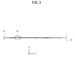
- Z value refers to the SAG, which expresses the shape of the f- ⁇ lens 30. Referring to FIGs. 2 and 3, if, based on an XYZ coordinate system, the main scanning plane is a Y-Z plane and the sub-scanning plane is an X-Z plane, the Z value shows changes along the direction of the Z axis according to positions in the directions of the X axis and the Y axis.
- Equation (1) constants are provided, for example, in TABLE 1 and TABLE 2 described below.
- Cx and Cy are curvatures that are reciprocal to the radius of curvature.
- the f- ⁇ lens 30 has a non-spherical shape in the main scanning direction, and the SAG change in the main scanning direction satisfies equation (2), below.
- the SAG change of the f- ⁇ lens 30 may be described graphically as shown in FIG. 4. - 0.2 ⁇ SAG ⁇ 1 + SAG ⁇ 2 d 2 ⁇ 0.2 where SAG 1 is the Z value of the incident surface 31 of the f- ⁇ lens 30, SAG 2 is the Z value of the exit surface 33 of the f- ⁇ lens, and d2 is a center thickness of the f- ⁇ lens 30.
- SAG 1 and SAG 2 have the shapes shown in FIG. 5A and FIG 6A respectively.
- the Z value is 0 mm at a center of the f- ⁇ lens 30 and increases towards both ends of the main scanning direction.
- the Z value shows a maximum value in a negative (-) direction at both ends and moves toward 0 mm at the center of the f- ⁇ lens 30.
- a ratio R1/R2 of the radius of curvature in the sub-scanning direction of the f- ⁇ lens 30 may satisfy equation (3) : 0 ⁇ R ⁇ 1 / R ⁇ 2 ⁇ 3.2 where R1 (which equals 1/CX1) is the radius of curvature of the incident surface 31 of the f- ⁇ lens 30 in the sub-scanning direction and R2 (which equals 1/CX2) is the radius of curvature of the exit surface 33 of the f- ⁇ lens 30 in the sub-scanning direction.
- the lower limit of zero (0) in the equation (3) indicates that the two radii of curvature have the same sign, which indicates that the f- ⁇ lens 30 has a meniscus configuration. If the upper limit in equation (3) is exceeded, the magnification of the f- ⁇ lens 30 is increased, thus having adverse effect on the finite optical system.
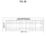
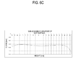
- the f- ⁇ lens 30 has a shape in the sub-scanning direction as shown in FIGs. 5B, 5C, 6B and 6C respectively.
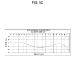
- FIGs. 5B and 5C are graphs respectively showing the sub-scanning radius of curvature and the sub-scanning curvature with regard to the height of the incident surface of the f- ⁇ lens 30.
- FIGs. 6B to 6C are graphs respectively showing the sub-scanning radius of curvature and the sub-scanning curvature with regard to the height of the exit surface of the f- ⁇ lens 30 of the light scanning unit shown in FIGs. 2 and 3.
- the magnification Ms_f ⁇ in the sub-scanning direction and the overall magnification deviation ⁇ Ms_tot may satisfy equations (4) and (5), respectively.
- Ms_f ⁇ having a negative sign means that a horizontal magnification in the sub-scanning direction has a negative (-) value, where an object and its image are reverse each other.
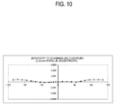
- FIGs. 9 and 10 are graphs showing the sensitivity to curvature of the scanning line in the case of an inclination eccentricity and a parallel eccentricity, respectively, of the light scanning unit shown in FIGs. 2 and 3.
- the curvature of the scanning line may be controlled to be equal to or less than about 1.3 ⁇ m. Also, if the f- ⁇ lens 30 has a 0.03 mm parallel eccentricity, the curvature of the scanning line may be controlled to be equal to or less than about 0.6 ⁇ m. Therefore, it is possible according to aspects of the present invention to realize a performance equal to or better than that of the above conventional technology where two f- ⁇ lenses are used.
- TABLE 1 and TABLE 2 show the configuration of the light scanning unit and lens data of the f- ⁇ lens, respectively, according to the present embodiment.
- the f- ⁇ lens 30 according to the present invention is not limited to a lens having the data shown in tables 1 and 2, and the f- ⁇ lens 30 can be varied as long as the conditions of equations 2 to 5 are satisfied.
- FIG. 11 is a schematic view of an image forming apparatus according to an embodiment of the present invention.
- the image forming apparatus is a tandem color image forming apparatus, and comprises a cabinet 110 and a photosensitive medium 130, a light scanning unit 140, a developing unit 150, a transfer unit 160, and a fixing unit 170, which are provided in the cabinet 110.
- the cabinet 110 forms an external housing of the image forming apparatus, and is provided with a discharging unit 111 at its outer surface to stack a discharged printable medium M.
- a supplying unit 120 is provided to be removable in the cabinet 110 so that the printable medium M can be loaded and re-supplied.
- the printable medium M supplied through the supplying unit 120 is conveyed through a conveying path in a direction to the developing unit 150.
- the supplying unit 120 picks up a sheet of the loaded printable medium M by rotation of the feeding roller 125, and supplies the picked up printable medium through a conveying roller 127.
- the photosensitive medium 130 is provided in the developing unit 150.
- the photosensitive medium 130 is sensitized by the beam scanned by the light scanning unit 140 to form an electrostatic latent image on its outer surface.
- the developing unit 150 comprises a toner container 151 accommodating a toner T therein; a developing roller 155 facing the photosensitive medium 130 and developing the toner to an area where the electrostatic latent image of the photosensitive medium 130 is formed, a supplying roller 156 supplying the toner T to the developing roller 155, and a charger 157 charging the photosensitive medium 130 to a predetermined electric potential. Also, a cleaning blade 159 may further be provided to remove a waste toner remaining on the photosensitive medium 130.
- FIG. 11 shows an embodiment comprising four units to transfer yellow (Y), magenta (M), cyan (C) and black (K).
- the light scanning unit 140 scans one or more light beams to form electrostatic latent images on each photosensitive medium 130.
- the light scanning unit 140 may have a multi-beam light scanning construction such that beams can be scanned simultaneously onto a plurality of the photosensitive media 130.
- the light scanning unit 140 may comprises light scanning sub-units, each scanning an individual photosensitive medium 130 and each comprising a light source (not shown), a beam deflector 141 that deflects and scans the beam irradiated by the light source, and an f- ⁇ lens 145 to form an image from the beam deflected by the beam deflector on the surface to be scanned, such as, for example, on a photosensitive medium 130 of the developing unit 150.
- the light source may comprise a plurality of luminescent points or may comprise a plurality of semiconductor devices, each of which has single luminescent point, to correspond to each color.
- the light scanning unit 140 may include two beam deflectors 141 each comprising a rotary polygonal mirror as shown in FIG. 11. In this case, each rotary polygonal mirror deflects and scans two beams irradiated by the light source through different paths.
- An f- ⁇ lens 145 is provided in each of the four paths through which a beam is deflected and scanned by the beam deflectors 141. In other words, one f- ⁇ lens 145 is provided in each path. Therefore, each beam may be scanned independently respect to the plurality of photosensitive media 130 that are adjacently placed.
- each light scanning sub-unit of the light scanning unit 140 Since the specific configuration of each light scanning sub-unit of the light scanning unit 140 is substantially the same as that of the light scanning unit of FIG. 2, a detailed description of each light scanning sub-unit is not repeated.
- the transfer unit 160 is located to face the photosensitive medium 130.
- the transfer unit 160 performs transferring of the toner image formed on the photosensitive medium 130 onto the supplied printable medium M.
- the transfer unit 160 comprises a transfer belt 161 and transfer back-up rollers 163 which are placed to face the plurality of photosensitive media 130.
- the image transferred onto the printable medium by the transfer unit 160 is fixed by the fixing unit 170.
- the fixing unit 170 comprises a heating roller 171, a pressing roller 175, and a heat source 177.
- the surface of the heating roller 171 is heated by heat generated by the heat source 177 and presses the printable medium against the pressing roller 175 to fix the transferred image on the printable medium.
- the sensitivity to the curvature of the scanning line due to the placement error of the f- ⁇ lens at the scanning surface may be enhanced by using a single f- ⁇ lens satisfying the conditions of the equations 2 to 5.
- the degree of freedom of the optical placement may be increased by using one f- ⁇ lens instead of a plurality of lenses, and productivity may be increased and manufacturing costs may be decreased by reducing the possibility of the occurrence of placement error.
- the physical arrangement and geometry of components of the image forming apparatus including the photosensitive medium, light scanning unit, developing unit, transfer unit and fixing unit may be different from what is shown.
- the physical arrangement and geometry of components of the multi-beam light scanning unit including the arrangement and number of light scanning sub-units and beam deflectors may be different from what is shown.
- the physical arrangement and geometry of components of an image forming apparatus containing the multi-beam light scanning unit including number and arrangement of photosensitive media, light scanning sub-unit, developing units, transfer units and fixing units may be different from what is shown. Accordingly, it is intended, therefore, that the present invention not be limited to the various example embodiments disclosed, but that the present invention includes all embodiments falling within the scope of the appended claims.
Landscapes
- Physics & Mathematics (AREA)
- General Physics & Mathematics (AREA)
- Optics & Photonics (AREA)
- Facsimile Scanning Arrangements (AREA)
- Laser Beam Printer (AREA)
- Mechanical Optical Scanning Systems (AREA)
Abstract

where SAG 1 is Z value of an incident surface of the f-θ lens (30), which faces the beam deflector (20), SAG 2 is Z value of the exit surface of the f-θ lens (30), which faces the surface to be scanned, based on an XYZ coordinate system in which a main scanning plane is a Y-Z plane and a subscanning plane is an X-Z plane, and d2 is a center thickness of the f-θ lens (30).
Description
- The present invention relates to a light scanning unit that scans an incident beam to be deflected onto a photosensitive medium and to an image forming apparatus using the same. More particularly, the present invention relates to a light scanning unit that has a structure for enhancing its sensitivity to curvature of a scanning line at a scanning surface due to a placement error of an f-θ lens and an image forming apparatus using the same.
- Generally, a light scanning unit is employed in image forming apparatuses such as laser beam printers, digital copiers, facsimile machines and multi-functional devices. Such a light scanning unit is used to deflect a laser beam irradiated from a light source and scan the laser beam in a main scanning direction of a photosensitive medium. An electrostatic latent image is formed on the exposed medium through scanning by the light scanning unit (referred to as "main scanning") and by the movement of the exposed medium (referred to as "sub-scanning").
- The light scanning unit is also required to decrease the curvature of a scanning line on the scanning surface, which is associated with a placement error of an optical system.
- In the light scanning unit, generation of the curvature of the scanning line due to the placement error of the optical system depends on a shape of an optical component and a sub-scanning magnification. The optical component usually has the shape of a lens in the main scanning direction, and its operation is influenced by whether light that has passed through a collimating lens is a parallel light or a converging light and by the number and location of f-θ lenses. In addition, an average and a deviation of the sub-scanning magnification are important factors in determining the magnification by the number and the location of the f-θ lenses and radii of curvature of an incident surface and an exit surface of the f- θ lenses.
- Such a conventional light scanning unit is described in
Japanese Laid-open Patent Publication No. 2004-184655 light source 1 that generates and irradiates a beam, abeam deflector 5 that deflects an incident beam to scan the beam irradiated by thelight source 1 onto an exposedmedium 8, and an f-θ lens 9 that corrects an error contained in the beam deflected by thebeam deflector 5. The conventional light scanning unit (see Figure 1a) may also include adiaphragm 2, acollimating lens 3 that collects the beam irradiated by thelight source 1, via thediaphragm 2, to be a parallel beam, and acylindrical lens 4 that shapes the beam. Thediaphragm 2, collimatinglens 3 andcylindrical lens 4 are installed in an optical path between thelight source 1 and thebeam deflector 5. - The
beam deflector 5 comprises a rotary polygonal mirror rotated by a driving source (not shown). The beam irradiated by thelight source 1 changes its direction while it is reflected by the rotatingbeam deflector 5, thus determining a scanning direction. That is, if the rotary polygonal mirror rotates in a direction A, the incident beam is reflected by a reflectingsurface 5a of the rotary polygonal mirror and scanned in a main scanning direction B onto a scanning surface of the exposedmedium 8. - The f-
θ lens 9 comprises two lenses, afirst lens 6 and asecond lens 7. Thefirst lens 6 has a meniscus shape in its main scanning sectional view, and thus has a positive refractive power. If "fm" is a focal distance in the main scanning surface of the exposedmedium 8 and d1 is a center thickness of thefirst lens 6, a condition of d1/fm < 0.06 is satisfied. Thesecond lens 7 has a surface corresponding to the incident beam that is formed as a non-spherical surface or an oval surface without an inflection point, in a sub-scanning direction. If R is the radius of curvature on a beam axis in the main scanning surface sectional view of the surface corresponding to the incident beam, a condition of 2.5 < |R/fm| is satisfied. - Therefore, according to the conventional light scanning unit, the curvature of the scanning line can be minimized by lens placement and conditions mentioned above when there is a parallel eccentricity that corresponds to a movement of the f-
θ lens 9 in the sub-scanning direction. - On the other hand, since the conventional light scanning unit as described with reference to FIG. 1A and FIG. 1B is configured as an infinite optical system, where the beam that has passed through the
collimating lens 3 is scanned parallel and two f-θ lenses 9 are used to improve the sensitivity to curvature of a scanning line, there is a disadvantage in that a degree of freedom of the lens placement is decreased or limited. Accordingly, if a tandem type light scanning unit is symmetrically configured to center around the beam deflector, the degree of freedom of an optical placement is inevitably decreased. - In addition, when two f-
θ lenses 9 are used, even if the sensitivity is sufficiently decreased in an optical design, the possibility of occurrence of a placement error is high compared to when a single f-θ lens is used. As a result, the possibility of a lowered performance is increased. Moreover, the manufacturing cost is higher and likewise, the productivity in manufacturing the conventional light scanning unit is lower, compared to a light scanning unit having a single f-θ lens. - The present invention provides a light scanning unit and image forming apparatus, where a sensitivity to curvature of a scanning line at a scanning surface due to a placement error of an f-θ lens is enhanced, a degree of freedom of an optical placement is increased by using a single f-θ lens, productivity is increased by reducing the possibility of the occurrence of a placement error and a manufacturing costs are reduced.
- Additional aspects and/or advantages of the invention will be set forth in part in the description which follows and, in part, will be obvious from the description, or may be learned by practice of the invention.
- According to the present invention there is provided an apparatus and method as set forth in the appended claims. Other features of the invention will be apparent from the dependent claims, and the description which follows.
- According to an aspect of the present invention, a light scanning unit is provided with a light source to generate and irradiate at least one beam corresponding to an image signal; a beam deflector to deflect and scan the beam irradiated by the light source; and an f-θ lens to form an image from the beam deflected by the beam deflector onto a surface to be scanned, the f-θ lens being provided as a single lens having a shape that satisfies the following equation (2):

whereSAG 1 is the Z value of the incident surface of the f-θ lens,SAG 2 is the Z value of the exit surface of the f-θ lens based on an XYZ coordinate system in which a main scanning plane is an Y-Z plane and a sub-scanning plane is an X-Z plane, and d2 is a center thickness of the f-θ lens. - Preferably, a ratio R1/R2 of a radius of curvature in a sub-scanning direction of the f-θ lens satisfies the following equation (3):

where R1 is a radius of curvature of the incident surface and R2 is a radius of curvature of the exit surface. - Preferably, a sub-scanning magnification Ms_fθ of the f-θ lens satisfies the following equation (4):

- Preferably, the light scanning unit further comprises a collimating lens that collects the beam irradiated by the light source, and a cylindrical lens that corrects the beam irradiated to the beam deflector, wherein the collimating lens and the cylindrical lens are provided in a beam path between the light source and the beam deflector.
- Preferably, an overall magnification deviation ΔMs_tot caused by the collimating lens, the cylindrical lens and the f-θ lens satisfies the following equation(5):

- Preferably, the collimating lens is positioned so that the beam in the main scanning direction from the collimating lens to the f-θ lens is not a parallel beam.
- According to another aspect of the present invention, there is provided an image forming apparatus comprising a photosensitive medium where an electrostatic latent image is formed; a light scanning unit to scan a beam onto the photosensitive medium to form the electrostatic latent image; a developing unit to form a toner image on the photosensitive medium; a transfer unit to transfer the toner image formed on the photosensitive medium onto a printable medium; and a fixing unit to fix the image transferred onto the printable medium, wherein the light scanning unit comprises a beam deflector to deflect and scan the beam irradiated by the light source; and an f-θ lens to form an image from the beam deflected by the beam deflector onto a surface to be scanned, the f-θ lens being provided as a single lens having a shape that satisfies the following equation (2):

whereSAG 1 is the Z value of the incident surface of the f-θ lens,SAG 2 is the Z value of the exit surface of the f-θ lens based on an XYZ coordinate system in which a main scanning plane is an Y-Z plane and a sub-scanning plane is an X-Z plane, and d2 is a center thickness of the f-θ lens. - Preferably, the light scanning unit of the image forming apparatus further comprises a collimating lens to collect the beam irradiated by the light source, and a cylindrical lens to correct the beam irradiated to the beam deflector, wherein the collimating lens and the cylindrical lens are provided in a beam path between the light source and the beam deflector.
- Preferably, an overall magnification deviation ΔMs_tot caused by the collimating lens, the cylindrical lens and the f-θ lens of the light scanning unit of the image forming apparatus satisfies the following equation 5:

- Preferably, the collimating lens of the light scanning unit of the image forming apparatus is positioned so that the beam in the main scanning direction from the collimating lens to the f-θ lens is not a parallel beam.
- According to another aspect of the present invention, there is provided a light scanning unit comprising a light source to generate and irradiate one or more beams, each corresponding to an image signal; one or more beam deflectors, each arranged to deflect and scan at least one of the one or more beams irradiated by the light source; and one or more f-θ lenses, each arranged to form an image on a surface of an exposed medium from one of the one or more beams deflected by the one of the one or more beam deflectors; wherein each f-θ lens is a single lens having a shape that satisfies the following equation (2):

whereSAG 1 is the Z value of the incident surface of the f-θ lens,SAG 2 is the Z value of the exit surface of the f-θ lens, based on an XYZ coordinate system in which a main scanning plane is an Y-Z plane and a sub-scanning plane is an X-Z plane, and d2 is a center thickness of the f-θ lens. - According to another aspect of the present invention, there is provided an image forming apparatus comprising a plurality of photosensitive media where electrostatic latent images are formed; a multi-beam light scanning unit; a plurality of developing units, each that forming a toner image on one of the plurality the photosensitive medium; a transfer unit that transfers the toner image formed on each of the plurality of photosensitive media onto a printable medium to form an image; and a fixing unit that fixes the image transferred onto the printable medium, wherein the multi-beam light scanning unit comprises a light source to generate and irradiate a plurality of beams, each corresponding to an image signal; one or more beam deflectors, each arranged to deflect and scan at least one of the plurality of beams irradiated by the light source; and a plurality of f-θ lenses, each arranged to form an image on a surface of an exposed medium from one of the plurality of beams deflected by the one of the one or more beam deflectors; wherein each f-θ lens is a single lens having a shape that satisfies the following equation (2):,

whereSAG 1 is the Z value of the incident surface of the f-θ lens,SAG 2 is the Z value of the exit surface of the f-θ lens, based on an XYZ coordinate system in which a main scanning plane is an Y-Z plane and a sub-scanning plane is an X-Z plane, and d2 is a center thickness of the f-θ lens. - In addition to the example embodiments and aspects as described above, further aspects and embodiments will be apparent by reference to the drawings and by study of the following descriptions.
- A better understanding of the present invention will become apparent from the following detailed description of example embodiments and the claims when read in connection with the accompanying drawings, all forming a part of the disclosure of this invention. While the following written and illustrated disclosure focuses on disclosing example embodiments of the invention, it should be clearly understood that the same is by way of illustration and example only and that the invention is not limited thereto. The scope of the present invention is limited only by the terms of the appended claims. The following represents brief descriptions of the drawings, wherein:
- FIG. 1A and FIG. 1B are schematic views showing an optical path of a conventional light scanning unit.
- FIG. 2 is a schematic view showing an optical path in a main scanning plane of a light scanning unit according to an embodiment of the present invention.
- FIG. 3 is a schematic view showing an optical path in a sub-scanning plane of the light scanning unit of the light scanning unit of FIG. 2.
(In FIGs. 2 and 3, based on an XYZ coordinate system, the main scanning plane is the Y-Z plane and the sub-scanning plane is the X-Z plane.) - FIG. 4 is a graph showing SAG changes in a main scanning direction with regard to height of the f-θ lens of the light scanning unit of FIGs. 2 and 3.
- FIGs. 5A to 5C are graphs respectively showing main SAG, sub-scanning radius of curvature and sub-scanning curvature with regard to height of an incident surface of the f-θ lens of the light scanning unit of FIGs. 2 and 3.
- FIGs. 6A to 6C are graphs respectively showing main SAG, sub-scanning radius of curvature and sub-scanning curvature with regard to height of an exit surface of the f-θ lens of the light scanning unit of FIGs. 2 and 3.
- FIG. 7 is a graph showing a sub-scanning magnification of the f-θ lens of the light scanning unit of FIGs. 2 and 3.
- FIG. 8 is a graph showing a deviation of the sub-scanning magnification of the f-θ lens of the light scanning unit of FIGs. 2 and 3.
- FIG. 9 is a graph showing sensitivity to curvature of a scanning line when there is an inclination eccentricity of the light scanning unit of FIGs. 2 and 3.
- FIG. 10 is a graph showing the sensitivity to curvature of the scanning line when there is a parallel eccentricity of the light scanning unit of FIGs. 2 and 3.
- FIG. 11 is a schematic view showing an image forming apparatus according to an embodiment of the present invention.
- Reference will now be made in detail to the present embodiments of the present invention, examples of which are illustrated in the accompanying drawings, wherein like reference numerals refer to like elements throughout. The embodiments are described below in order to explain the present invention by referring to the figures.
- Referring to FIG. 2, a light scanning unit according to an example embodiment of the present invention is an apparatus that scans a beam in a main scanning direction D onto a
scanning surface 40 of an exposed medium, which moves in a sub-scanning direction. The sub-scanning direction may be perpendicular to the main scanning direction D. As shown in FIG. 2, the light scanning unit comprises alight source 11, abeam deflector 20, and an f-θ lens 30. - The
light source 11 is controlled in an on/off manner by a driving circuit (not shown) and irradiates at least one beam corresponding to an image signal. Thelight source 11 may comprise a semiconductor device such as, for example, a semiconductor laser, a light-emitting diode (LED) or other known devices in the art. Also, thelight source 11 may irradiate a single beam or a multi-beam. For example, a multi-beam may be irradiated simultaneously if thelight source 11 comprises a semiconductor device having a plurality of luminescent points. Such a light source can be used in a tandem image forming apparatus, which forms a color image in a single pass. Since light sources are generally known to those skilled in the art, a detail description of thelight source 11 is omitted in this specification. - The
beam deflector 20 deflects and scans the beam irradiated by thelight source 11, so that the beam can be scanned in a main scanning direction with regard to thescanning surface 40 of the exposed medium. As a non-limiting example, thebeam deflector 20 may be a polygonal mirror apparatus as shown in FIG. 2. The polygonal mirror apparatus comprises a driving source (not shown) and a rotarypolygonal mirror 21 that is rotated in a predetermined direction, such as, for example, a clockwise direction (direction C) by the driving source. The rotarypolygonal mirror 21 has a plurality ofreflective surfaces 21a on its sides to deflect and scan an incident beam while the rotarypolygonal mirror 21 rotates. For example, the rotarypolygonal mirror 21 may have six or morereflective surfaces 21a, considering the scanning speed and the optical path. The rotarypolygonal mirror 21 may also have an external diameter of its circumscribed circle equal to or less than 30 mm, and a thickness equal to or more than 2 mm. However, thebeam deflector 20 is not limited to the polygonal mirror apparatus as described in FIG. 2 and may be a hologram disc type beam deflector which deflects and scans the incident beam, a galvano-mirror type beam deflector or other known beam deflectors used to deflect a light beam. - A collimating
lens 13 and acylindrical lens 17 may be provided in the optical path between thelight source 11 and thebeam deflector 20. The collimatinglens 13 collects the beam irradiated by thelight source 11 to be a converging light. That is, in placing thecollimating lens 13, it is preferable but not necessary that the beam have a constitution such as in a finite optical system where an angle of the beam in the main scanning direction from the collimatinglens 13 to the f-θ lens 30 is not parallel, but rather is converging. - The
cylindrical lens 17 has a predetermined refractive power only in the sub-scanning direction, corrects the beam having passed through the collimatinglens 13 and performs imaging of the beam linearly on thebeam deflector 20. Furthermore, adiaphragm 15 may be provided between thelight source 11 and thecylindrical lens 17 to adjust the diameter of the penetrating beam. - The f-
θ lens 30 is provided as a single lens having anincident surface 31 and anexit surface 33. The f-θ lens 30 corrects the beam deflected and scanned by thebeam deflector 20 to have different magnifications between the main scanning direction and the sub-scanning direction, so that the scanning line may form an image on thescanning surface 40 of the exposed medium. As a non-limiting example, the f-θ lens 30 may comprise a plastic non-spherical lens and at least one of theincident surface 31 and theexit surface 33 may have a non-spherical surface or a free curve surface where a curvature in the sub-scanning direction changes continuously. As used herein, the term "main scanning direction" refers to a direction D in which the beam is deflected through thebeam deflector 20, and the term "sub-scanning direction" refers to a direction in which the exposed medium moves. - The light scanning unit according to aspects of the present invention may further comprise a synchronous detector (not shown) that detects a scanning start position, and a reflective mirror (not shown) provided in an optical path between the
beam deflector 20 and thescanning surface 40 of the exposed medium that changes a scanning beam path. - Hereinafter, a condition is described where the curvature of the scanning line at the
scanning surface 40 of the exposed medium due to a placement error of the f-θ lens can be minimized by the single f-θ lens 30. - The shape of the f-
θ lens 30 has a Z value that satisfies an equation (1), below. The term "Z value" refers to the SAG, which expresses the shape of the f-θ lens 30. Referring to FIGs. 2 and 3, if, based on an XYZ coordinate system, the main scanning plane is a Y-Z plane and the sub-scanning plane is an X-Z plane, the Z value shows changes along the direction of the Z axis according to positions in the directions of the X axis and the Y axis. - In equation (1), constants are provided, for example, in TABLE 1 and TABLE 2 described below.

where Cx and Cy are curvatures that are reciprocal to the radius of curvature. - The f-
θ lens 30 has a non-spherical shape in the main scanning direction, and the SAG change in the main scanning direction satisfies equation (2), below. In this case, the SAG change of the f-θ lens 30 may be described graphically as shown in FIG. 4.
whereSAG 1 is the Z value of theincident surface 31 of the f-θ lens 30,SAG 2 is the Z value of theexit surface 33 of the f-θ lens, and d2 is a center thickness of the f-θ lens 30. - To satisfy a condition of equation (2),
SAG 1 andSAG 2 have the shapes shown in FIG. 5A and FIG 6A respectively. Referring to the representation ofSAG 1 in FIG 5A, the Z value is 0 mm at a center of the f-θ lens 30 and increases towards both ends of the main scanning direction. Also, referring to the representation ofSAG 2 in FIG 6A, the Z value shows a maximum value in a negative (-) direction at both ends and moves toward 0 mm at the center of the f-θ lens 30. - A ratio R1/R2 of the radius of curvature in the sub-scanning direction of the f-
θ lens 30 may satisfy equation (3) :
where R1 (which equals 1/CX1) is the radius of curvature of theincident surface 31 of the f-θ lens 30 in the sub-scanning direction and R2 (which equals 1/CX2) is the radius of curvature of theexit surface 33 of the f-θ lens 30 in the sub-scanning direction. - The lower limit of zero (0) in the equation (3) indicates that the two radii of curvature have the same sign, which indicates that the f-
θ lens 30 has a meniscus configuration. If the upper limit in equation (3) is exceeded, the magnification of the f-θ lens 30 is increased, thus having adverse effect on the finite optical system. - To reduce the sensitivity to the curvature of the scanning line as well as satisfy equation (3), the f-
θ lens 30 has a shape in the sub-scanning direction as shown in FIGs. 5B, 5C, 6B and 6C respectively. FIGs. 5B and 5C are graphs respectively showing the sub-scanning radius of curvature and the sub-scanning curvature with regard to the height of the incident surface of the f-θ lens 30. FIGs. 6B to 6C are graphs respectively showing the sub-scanning radius of curvature and the sub-scanning curvature with regard to the height of the exit surface of the f-θ lens 30 of the light scanning unit shown in FIGs. 2 and 3. - As a non-limiting example, the magnification Ms_fθ in the sub-scanning direction and the overall magnification deviation ΔMs_tot may satisfy equations (4) and (5), respectively.

where Ms_fθ having a negative sign means that a horizontal magnification in the sub-scanning direction has a negative (-) value, where an object and its image are reverse each other. - Also, if the lower limit of the equation is exceeded, the magnification becomes increased in the constitution of the finite system using the single f-θ lens, thus lowering the lens performance. These relations are graphically shown in FIG. 7.

where ΔMs_tot means the overall magnification deviation caused by the collimating lens, the cylindrical lens and the f-θ lens. - With the data values according to the embodiment of the present invention as set forth below, the condition of ΔMs_tot ≤ +1 [%] is arrived at, thus satisfying the condition of
equation 5. Also, this relation is graphically shown in FIG. 8. - FIGs. 9 and 10 are graphs showing the sensitivity to curvature of the scanning line in the case of an inclination eccentricity and a parallel eccentricity, respectively, of the light scanning unit shown in FIGs. 2 and 3.
- Referring to FIGs. 9 and 10, if the f-
θ lens 30 has a 3 minute inclination eccentricity, the curvature of the scanning line may be controlled to be equal to or less than about 1.3 µm. Also, if the f-θ lens 30 has a 0.03 mm parallel eccentricity, the curvature of the scanning line may be controlled to be equal to or less than about 0.6 µm. Therefore, it is possible according to aspects of the present invention to realize a performance equal to or better than that of the above conventional technology where two f-θ lenses are used. - Hereinafter, the optical performance of the light scanning unit according to aspects of the present invention is described through specific embodiments satisfying equations (1) to (5).
- TABLE 1 and TABLE 2 show the configuration of the light scanning unit and lens data of the f-θ lens, respectively, according to the present embodiment.
TABLE 1 Wavelength λ (nm) 780 Incident angle (°) 75 Beam deflector Diameter of outer tangential circumscribed circle (mm) 30 Number of Surfaces 6 Scanning angle +Y(°) 37.2 -Y(°) -37.2 Beam path d1 (mm) 52.5 d2 (mm) 15 d3 (mm) 131.2 TABLE 2 f-θ lens (incident surface) f-θ lens (exit surface) f-θ lens (incident surface) f-θ lens (exit surface) Cy 7.863E-03 6.687E-04 A10(-y) -1.140E-16 -7.555E-16 Cx -4.406E-02 -7.094E-02 B3(+y) -3.550E-05 -1.506E-05 Ky 0.000E+00 0.000E+00 B4(+y) 1.096E-06 8.560E-07 A3(+y) 9.654E-05 1.163E-04 B5(+y) -5.748E-09 -2.135E-08 A4(+y) -1.795E-05 -1.950E-05 B6(+y) 1.301E-10 8.518E-11 A5(+y) 1.095E-06 1.238E-06 B7(+y) -8.200E-12 9.430E-12 A6(+y) -3.720E-08 -4.717E-08 B8(+y) 4.075E-14 -1.827E-13 A7(+y) 7.131E-10 1.154E-09 B9(+y) 2.252E-15 3.058E-16 A8(+y) -7.494E-12 -1.843E-11 B10(+y) -2.289E-17 1.181E-17 A9(+y) 3.987E-14 1.772E-13 B3(-y) -8.986E-05 -3.847E-05 A10(+y) -9.199E-17 -7.722E-16 B4(-y) 5.311E-06 3.555E-06 A3(-y) 1.149E-04 1.368E-04 B5(-y) -9.817E-08 -1.688E-07 A4(-y) -1.921E-05 -2.071E-05 B6(-y) -7.236E-10 4.374E-09 A5(-y) 1.120E-06 1.266E-06 B7(-y) 4.312E-11 -3.951E-11 A6(-y) -3.701E-08 -4.740E-08 B8(-y) -2.900E-13 -7.834E-13 A7(-y) 7.029E-10 1.154E-09 B9(-y) -1.653E-15 2.224E-14 A8(-y) -7.501E-12 -1.837E-11 B10(-y) 5.992E-18 -1.537E-16 A9(-y) 4.264E-14 1.755E-13 - In the above light scanning unit, since CX1 = -4.406E-2 and Cx2 = -7.094E-2, R1/R2 = (1/Cx1)/(1/Cx2)= -7.094E-2/-4.406E-2 ≈1.61, thus satisfying equation (3). Also, if Ms_fθ is calculated from data according to the above example, Ms_fθ is -1.73355, thus satisfying equation (4).
- However, the f-
θ lens 30 according to the present invention is not limited to a lens having the data shown in tables 1 and 2, and the f-θ lens 30 can be varied as long as the conditions ofequations 2 to 5 are satisfied. - FIG. 11 is a schematic view of an image forming apparatus according to an embodiment of the present invention. Referring to FIG. 11, the image forming apparatus is a tandem color image forming apparatus, and comprises a
cabinet 110 and aphotosensitive medium 130, alight scanning unit 140, a developingunit 150, atransfer unit 160, and afixing unit 170, which are provided in thecabinet 110. - The
cabinet 110 forms an external housing of the image forming apparatus, and is provided with a dischargingunit 111 at its outer surface to stack a discharged printable medium M. A supplyingunit 120 is provided to be removable in thecabinet 110 so that the printable medium M can be loaded and re-supplied. The printable medium M supplied through the supplyingunit 120 is conveyed through a conveying path in a direction to the developingunit 150. In more detail, the supplyingunit 120 picks up a sheet of the loaded printable medium M by rotation of the feedingroller 125, and supplies the picked up printable medium through a conveyingroller 127. - The
photosensitive medium 130 is provided in the developingunit 150. Thephotosensitive medium 130 is sensitized by the beam scanned by thelight scanning unit 140 to form an electrostatic latent image on its outer surface. - The developing
unit 150 comprises atoner container 151 accommodating a toner T therein; a developingroller 155 facing thephotosensitive medium 130 and developing the toner to an area where the electrostatic latent image of thephotosensitive medium 130 is formed, a supplying roller 156 supplying the toner T to the developingroller 155, and acharger 157 charging thephotosensitive medium 130 to a predetermined electric potential. Also, acleaning blade 159 may further be provided to remove a waste toner remaining on thephotosensitive medium 130. - A separate developing
unit 150 and thephotosensitive medium 130 may be provided for each color such that a full color image can be formed by single pass. FIG. 11 shows an embodiment comprising four units to transfer yellow (Y), magenta (M), cyan (C) and black (K). - The
light scanning unit 140 scans one or more light beams to form electrostatic latent images on eachphotosensitive medium 130. To this end, thelight scanning unit 140 may have a multi-beam light scanning construction such that beams can be scanned simultaneously onto a plurality of thephotosensitive media 130. Thelight scanning unit 140 may comprises light scanning sub-units, each scanning an individualphotosensitive medium 130 and each comprising a light source (not shown), abeam deflector 141 that deflects and scans the beam irradiated by the light source, and an f-θ lens 145 to form an image from the beam deflected by the beam deflector on the surface to be scanned, such as, for example, on aphotosensitive medium 130 of the developingunit 150. In a color image forming apparatus, the light source may comprise a plurality of luminescent points or may comprise a plurality of semiconductor devices, each of which has single luminescent point, to correspond to each color. Also, thelight scanning unit 140 may include twobeam deflectors 141 each comprising a rotary polygonal mirror as shown in FIG. 11. In this case, each rotary polygonal mirror deflects and scans two beams irradiated by the light source through different paths. An f-θ lens 145 is provided in each of the four paths through which a beam is deflected and scanned by thebeam deflectors 141. In other words, one f-θ lens 145 is provided in each path. Therefore, each beam may be scanned independently respect to the plurality ofphotosensitive media 130 that are adjacently placed. - Since the specific configuration of each light scanning sub-unit of the
light scanning unit 140 is substantially the same as that of the light scanning unit of FIG. 2, a detailed description of each light scanning sub-unit is not repeated. - The
transfer unit 160 is located to face thephotosensitive medium 130. Thetransfer unit 160 performs transferring of the toner image formed on thephotosensitive medium 130 onto the supplied printable medium M. To this end, thetransfer unit 160 comprises atransfer belt 161 and transfer back-uprollers 163 which are placed to face the plurality ofphotosensitive media 130. The image transferred onto the printable medium by thetransfer unit 160 is fixed by the fixingunit 170. - The fixing
unit 170 comprises aheating roller 171, apressing roller 175, and aheat source 177. The surface of theheating roller 171 is heated by heat generated by theheat source 177 and presses the printable medium against thepressing roller 175 to fix the transferred image on the printable medium. - As described above, according to the light scanning unit and the image forming apparatus using the same according to aspects of the present invention, the sensitivity to the curvature of the scanning line due to the placement error of the f-θ lens at the scanning surface may be enhanced by using a single f-θ lens satisfying the conditions of the
equations 2 to 5. Also, the degree of freedom of the optical placement may be increased by using one f-θ lens instead of a plurality of lenses, and productivity may be increased and manufacturing costs may be decreased by reducing the possibility of the occurrence of placement error. - While there have been illustrated and described what are considered to be example embodiments of the present invention, it will be understood by those skilled in the art and as technology develops that various changes and modifications, may be made, and equivalents may be substituted for elements thereof without departing from the true scope of the present invention. Many modifications, permutations, additions and subcombinations may be made to adapt the teachings of the present invention to a particular situation without departing from the scope thereof. For example, the physical arrangement and geometry of components of the light scanning unit including the light source, collimating lens, cylindrical lens, beam deflector may be different from what is shown. The collimating lens and cylindrical lens may be omitted, or more than one collimating lens and cylindrical lens may be provided. Moreover, the physical arrangement and geometry of components of the image forming apparatus, including the photosensitive medium, light scanning unit, developing unit, transfer unit and fixing unit may be different from what is shown. Moreover, the physical arrangement and geometry of components of the multi-beam light scanning unit, including the arrangement and number of light scanning sub-units and beam deflectors may be different from what is shown. Moreover, the physical arrangement and geometry of components of an image forming apparatus containing the multi-beam light scanning unit, including number and arrangement of photosensitive media, light scanning sub-unit, developing units, transfer units and fixing units may be different from what is shown. Accordingly, it is intended, therefore, that the present invention not be limited to the various example embodiments disclosed, but that the present invention includes all embodiments falling within the scope of the appended claims.
- Attention is directed to all papers and documents which are filed concurrently with or previous to this specification in connection with this application and which are open to public inspection with this specification, and the contents of all such papers and documents are incorporated herein by reference.
- All of the features disclosed in this specification (including any accompanying claims, abstract and drawings), and/or all of the steps of any method or process so disclosed, may be combined in any combination, except combinations where at least some of such features and/or steps are mutually exclusive.
- Each feature disclosed in this specification (including any accompanying claims, abstract and drawings) may be replaced by alternative features serving the same, equivalent or similar purpose, unless expressly stated otherwise. Thus, unless expressly stated otherwise, each feature disclosed is one example only of a generic series of equivalent or similar features.
- The invention is not restricted to the details of the foregoing embodiment(s). The invention extends to any novel one, or any novel combination, of the features disclosed in this specification (including any accompanying claims, abstract and drawings), or to any novel one, or any novel combination, of the steps of any method or process so disclosed.
Claims (17)
- A light scanning unit comprising:a light source (11) to generate and irradiate at least one beam corresponding to an image signal;a beam deflector (20) to deflect and scan the beam irradiated by the light source (11); andan f-θ lens (30) to form an image from the beam deflected by the beam deflector (20) onto a surface to be scanned,wherein the f-θ lens (30) is a single lens having a shape that satisfies the following equation (2):,

where SAG 1 is the Z value of an incident surface of the f-θ lens (30), SAG 2 is the Z value of an exit surface of the f-θ lens (30), based on an XYZ coordinate system in which a main scanning plane is a Y-Z plane and a sub-scanning plane is an X-Z plane, and d2 is a center thickness of the f-θ lens (30). - The light scanning unit according to claim 1, wherein a ratio R1/R2 of a radius of curvature in a sub-scanning direction of the f-θ lens (30) satisfies the following equation (3):

where R1 is a radius of curvature of the incident surface and R2 is a radius of curvature of the exit surface. - The light scanning unit according to claim 2, wherein a sub-scanning magnification Ms_fθ of the f-θ lens (30) satisfies the following equation (4):

- The light scanning unit as claimed in any one of claims 1 to 3, further comprising a collimating lens (13) that collects the beam irradiated by the light source (11), and a cylindrical lens (17) that corrects the beam irradiated to the beam deflector (20),
wherein the collimating lens (13) and the cylindrical lens (17) are provided in a beam path between the light source (11) and the beam deflector (20). - The light scanning unit according to claim 4, wherein an overall magnification deviation ΔMs_tot caused by the collimating lens (13), the cylindrical lens (17) and the f-θ lens (30) satisfies the following equation (5):

- The light scanning unit according to claim 4, wherein the collimating lens (13) is positioned so that the beam in a main scanning direction from the collimating lens (13) to the f-θ lens (30) is not a parallel beam.
- An image forming apparatus comprising:a photosensitive medium (130) where an electrostatic latent image is formed;a light scanning unit (140) as claimed in any one of claims 1 to 3 that scans a beam onto the photosensitive medium (130) to form the electrostatic latent image;a developing unit (150) to form a toner image on the photosensitive medium (130);a transfer unit (160) to transfer the toner image formed on the photosensitive medium (130) onto a printable medium; anda fixing unit (170) to fix the image transferred onto the printable medium.
- The image forming apparatus according to claim 7, wherein the light scanning unit (140) further comprises a collimating lens (13) that collects the beam irradiated by the light source (11), and a cylindrical lens (17) that corrects the beam irradiated to the beam deflector (20),
wherein the collimating lens (13) and the cylindrical lens (17) are provided in a beam path between the light source (11) and the beam deflector (20). - The image forming apparatus according to claim 8, wherein an overall magnification deviation ΔMs_tot caused by the collimating lens (13), the cylindrical lens (17) and the f-θ lens (30) satisfies the following equation (5):

- The image forming apparatus according to claim 8, wherein the collimating lens (13) is positioned so that the beam in the main scanning direction from the collimating lens (13) to the f-θ lens (30) is not a parallel beam.
- A light scanning unit comprising:a light source (11) to generate and irradiate one or more beams, each corresponding to an image signal;one or more beam deflectors (141), each arranged to deflect and scan at least one of the one or more beams irradiated by the light source (11); andone or more f-θ lenses, each arranged to form an image on a surface of an exposed medium from one of the one or more beams deflected by the one of the one or more beam deflectors (141);wherein each f-θ lens (30) is a single lens having a shape that satisfies the following equation (2):,

where SAG 1 is the Z value of the incident surface of the f-θ lens (30), SAG 2 is the Z value of the exit surface of the f-θ lens (30), based on an XYZ coordinate system in which a main scanning plane is a Y-Z plane and a sub-scanning plane is an X-Z plane, and d2 is a center thickness of the f-θ lens (30). - The light scanning unit according to claim 11, wherein for each f-θ lens (30), a ratio R1/R2 of a radius of curvature in a sub-scanning direction of the f-θ lens (30) satisfies the following equation (3):

where R1 is a radius of curvature of the incident surface and R2 is a radius of curvature of the exit surface. - The light scanning unit according to claim 11, wherein for each f-θ lens (30), a sub-scanning magnification Ms_fθ of the f-θ lens (30) satisfies the following equation (4):

- The light scanning unit as claimed in either of claims 11 and 13, wherein the multi-beam light scanning unit (140) further comprises, for each one of the plurality of beams irradiated by the light source (11), a collimating lens (13) that collects the beam irradiated by the light source (11) and a cylindrical lens (17) that corrects the beam irradiated to the beam deflector (141),
wherein the collimating lens (13) and the cylindrical lens (17) are provided in a beam path between the light source (11) and the beam deflector (141). - The light scanning unit according to claim 14, wherein for each one of the plurality of beams irradiated by the light source (11), an overall magnification deviation ΔMs_tot caused by the collimating lens (13), the cylindrical lens (17) and the f-θ lens (30) satisfies the following equation (5):

- The light scanning unit according to claim 14, wherein for each one of the plurality of beams irradiated by the light source (11), the collimating lens (13) is positioned so that the beam in the main scanning direction from the collimating lens (13) to the f-θ lens (30) is not a parallel beam.
- An image forming apparatus comprising:a plurality of photosensitive media where electrostatic latent images are formed;a multi-beam light scanning unit (140);a plurality of developing units (150), each forming a toner image on one of the plurality the photosensitive medium (130);a transfer unit (160) that transfers the toner image formed on each of the plurality of photosensitive media onto a printable medium to form an image; anda fixing unit (170) that fixes the image transferred onto the printable medium,wherein the multi-beam light scanning unit (140) comprises a light source (11) to generate and irradiate a plurality of beams, each corresponding to an image signal;
one or more beam deflectors (141), each arranged to deflect and scan at least one of the plurality of beams irradiated by the light source (11); and
a plurality of f-θ lenses (145), each arranged to form an image on a surface of an exposed medium from one of the plurality of beams deflected by the one of the one or more beam deflectors (141);
wherein each f-θ lens (145) is a single lens having a shape that satisfies the following equation (2):,
where SAG 1 is the Z value of the incident surface of the f-θ lens (145), SAG 2 is the Z value of the exit surface of the f-θ lens (145), based on an XYZ coordinate system in which a main scanning plane is a Y-Z plane and a sub-scanning plane is an X-Z plane, and d2 is a center thickness of the f-θ lens (145).
Applications Claiming Priority (1)
| Application Number | Priority Date | Filing Date | Title |
|---|---|---|---|
| KR1020060109405A KR101236388B1 (en) | 2006-11-07 | 2006-11-07 | Light scanning unit and image forming apparatus using the same |
Publications (3)
| Publication Number | Publication Date |
|---|---|
| EP1921481A2 true EP1921481A2 (en) | 2008-05-14 |
| EP1921481A3 EP1921481A3 (en) | 2011-05-25 |
| EP1921481B1 EP1921481B1 (en) | 2013-04-03 |
Family
ID=39092792
Family Applications (1)
| Application Number | Title | Priority Date | Filing Date |
|---|---|---|---|
| EP07117331A Ceased EP1921481B1 (en) | 2006-11-07 | 2007-09-27 | Light scanning unit and image forming apparatus using the same |
Country Status (4)
| Country | Link |
|---|---|
| US (1) | US7710446B2 (en) |
| EP (1) | EP1921481B1 (en) |
| KR (1) | KR101236388B1 (en) |
| CN (1) | CN100549759C (en) |
Cited By (2)
| Publication number | Priority date | Publication date | Assignee | Title |
|---|---|---|---|---|
| EP2009482B1 (en) * | 2007-06-28 | 2010-09-15 | Canon Kabushiki Kaisha | Multi-beam optical scanning device and image forming apparatus using the same |
| EP3968077A4 (en) * | 2019-05-17 | 2022-06-22 | Zhuhai Pantum Electronics Co., Ltd. | OPTICAL SCANNING UNIT AND ELECTRONIC PHOTOGRAPHIC IMAGING DEVICE |
Families Citing this family (5)
| Publication number | Priority date | Publication date | Assignee | Title |
|---|---|---|---|---|
| JP6230586B2 (en) * | 2015-11-26 | 2017-11-15 | キヤノン株式会社 | Optical scanning device and image forming apparatus having the same |
| JP6429944B1 (en) * | 2017-05-30 | 2018-11-28 | キヤノン株式会社 | Optical scanning device and image forming apparatus having the same |
| CN109491077B (en) | 2018-12-29 | 2020-11-17 | 珠海奔图电子有限公司 | Optical scanning apparatus and electronic image forming apparatus |
| JP6986312B2 (en) * | 2019-03-14 | 2021-12-22 | ナルックス株式会社 | Scanning optics and scanning lens |
| CN112504474B (en) * | 2020-12-17 | 2022-02-15 | 天津欧菲光电有限公司 | Optical systems, lens modules and electronics |
Family Cites Families (12)
| Publication number | Priority date | Publication date | Assignee | Title |
|---|---|---|---|---|
| JPH07174997A (en) * | 1993-12-17 | 1995-07-14 | Fuji Xerox Co Ltd | Optical scanner |
| JP3445050B2 (en) | 1995-02-28 | 2003-09-08 | キヤノン株式会社 | Scanning optical device and multi-beam scanning optical device |
| JP3546898B2 (en) * | 1995-01-30 | 2004-07-28 | セイコーエプソン株式会社 | Optical scanning device |
| US6347004B1 (en) * | 1998-08-31 | 2002-02-12 | Ricoh Company, Ltd. | Optical scanning apparatus and scanning image forming lens |
| JP4684470B2 (en) * | 2001-06-08 | 2011-05-18 | キヤノン株式会社 | Optical scanning device and image forming apparatus using the same |
| JP4717285B2 (en) * | 2001-08-24 | 2011-07-06 | キヤノン株式会社 | Scanning optical device and image forming apparatus using the same |
| US7034859B2 (en) * | 2002-08-08 | 2006-04-25 | Canon Kabushiki Kaisha | Optical scanning device and image forming apparatus using the same |
| KR100474433B1 (en) | 2002-09-05 | 2005-03-10 | 삼성전자주식회사 | Apparatus for beam scanning |
| JP4378081B2 (en) | 2002-12-03 | 2009-12-02 | キヤノン株式会社 | Optical scanning device and image forming apparatus using the same |
| KR100490433B1 (en) | 2003-06-10 | 2005-05-17 | 삼성전자주식회사 | Laser scanning unit and f-θ lens |
| KR100619037B1 (en) * | 2004-07-02 | 2006-09-01 | 삼성전자주식회사 | Scanning optical lens having an asymmetric curvature and an optical scanning device employing the lens |
| KR200422353Y1 (en) | 2006-05-12 | 2006-07-25 | 공만수 | Battery showing remaining charge |
-
2006
- 2006-11-07 KR KR1020060109405A patent/KR101236388B1/en not_active Expired - Fee Related
-
2007
- 2007-06-05 US US11/758,229 patent/US7710446B2/en active Active
- 2007-09-27 EP EP07117331A patent/EP1921481B1/en not_active Ceased
- 2007-10-23 CN CNB2007101643323A patent/CN100549759C/en not_active Expired - Fee Related
Non-Patent Citations (1)
| Title |
|---|
| None |
Cited By (3)
| Publication number | Priority date | Publication date | Assignee | Title |
|---|---|---|---|---|
| EP2009482B1 (en) * | 2007-06-28 | 2010-09-15 | Canon Kabushiki Kaisha | Multi-beam optical scanning device and image forming apparatus using the same |
| EP3968077A4 (en) * | 2019-05-17 | 2022-06-22 | Zhuhai Pantum Electronics Co., Ltd. | OPTICAL SCANNING UNIT AND ELECTRONIC PHOTOGRAPHIC IMAGING DEVICE |
| US11822071B2 (en) | 2019-05-17 | 2023-11-21 | Zhuhai Pantum Electronics Co., Ltd. | Optical scanner and electrophotographic image forming apparatus |
Also Published As
| Publication number | Publication date |
|---|---|
| KR101236388B1 (en) | 2013-02-22 |
| CN100549759C (en) | 2009-10-14 |
| EP1921481B1 (en) | 2013-04-03 |
| US20080106586A1 (en) | 2008-05-08 |
| EP1921481A3 (en) | 2011-05-25 |
| CN101178478A (en) | 2008-05-14 |
| US7710446B2 (en) | 2010-05-04 |
| KR20080041376A (en) | 2008-05-13 |
Similar Documents
| Publication | Publication Date | Title |
|---|---|---|
| EP2863252A1 (en) | Optical scanning device and image forming apparatus using the same | |
| KR101078513B1 (en) | Optical scanning apparatus and image forming apparatus using the same | |
| EP2012146B1 (en) | Optical scanning device and image forming apparatus using the same | |
| EP2009482B1 (en) | Multi-beam optical scanning device and image forming apparatus using the same | |
| EP2051126A2 (en) | Optical scanning device and image forming apparatus using the same | |
| JP5014075B2 (en) | Optical scanning device and image forming apparatus using the same | |
| EP1921481B1 (en) | Light scanning unit and image forming apparatus using the same | |
| EP1939666B1 (en) | Optical scanning device and image forming apparatus using the same | |
| JP2004070108A (en) | Optical scanning device and image forming apparatus using the same | |
| US7550712B2 (en) | Optical scanning system with reduced spherical aberration and image forming apparatus using the same | |
| EP1336889B1 (en) | Scanning optical apparatus and image forming apparatus using the same | |
| KR100824093B1 (en) | Optical scanning device and image forming device using the same | |
| US20030063359A1 (en) | Optical scanner and image forming apparatus using the same | |
| JP2008170487A (en) | Optical scanning device and image forming apparatus using the same | |
| US20100165068A1 (en) | Optical beam scanning apparatus and image forming apparatus | |
| US20090116090A1 (en) | Optical beam scanning apparatus, method of manufacturing optical beam scanning apparatus, image forming apparatus and method of manufacturing image forming apparatus | |
| US7864391B2 (en) | Optical beam scanning apparatus and image forming apparatus | |
| JP5094221B2 (en) | Optical scanning device and image forming apparatus using the same | |
| JP2004317790A (en) | Optical scanning device | |
| JPH09184991A (en) | Optical scanning device and image forming apparatus using the optical scanning device | |
| JP2004198894A (en) | Scanning optical device and image forming apparatus using the same |
Legal Events
| Date | Code | Title | Description |
|---|---|---|---|
| PUAI | Public reference made under article 153(3) epc to a published international application that has entered the european phase |
Free format text: ORIGINAL CODE: 0009012 |
|
| 17P | Request for examination filed |
Effective date: 20070927 |
|
| AK | Designated contracting states |
Kind code of ref document: A2 Designated state(s): AT BE BG CH CY CZ DE DK EE ES FI FR GB GR HU IE IS IT LI LT LU LV MC MT NL PL PT RO SE SI SK TR |
|
| AX | Request for extension of the european patent |
Extension state: AL BA HR MK RS |
|
| PUAL | Search report despatched |
Free format text: ORIGINAL CODE: 0009013 |
|
| AK | Designated contracting states |
Kind code of ref document: A3 Designated state(s): AT BE BG CH CY CZ DE DK EE ES FI FR GB GR HU IE IS IT LI LT LU LV MC MT NL PL PT RO SE SI SK TR |
|
| AX | Request for extension of the european patent |
Extension state: AL BA HR MK RS |
|
| AKX | Designation fees paid |
Designated state(s): DE FR GB NL |
|
| RAP1 | Party data changed (applicant data changed or rights of an application transferred) |
Owner name: SAMSUNG ELECTRONICS CO., LTD. |
|
| GRAP | Despatch of communication of intention to grant a patent |
Free format text: ORIGINAL CODE: EPIDOSNIGR1 |
|
| RIN1 | Information on inventor provided before grant (corrected) |
Inventor name: KIM, HYUNG-SOO |
|
| GRAS | Grant fee paid |
Free format text: ORIGINAL CODE: EPIDOSNIGR3 |
|
| GRAA | (expected) grant |
Free format text: ORIGINAL CODE: 0009210 |
|
| AK | Designated contracting states |
Kind code of ref document: B1 Designated state(s): DE FR GB NL |
|
| REG | Reference to a national code |
Ref country code: GB Ref legal event code: FG4D |
|
| REG | Reference to a national code |
Ref country code: DE Ref legal event code: R096 Ref document number: 602007029445 Country of ref document: DE Effective date: 20130529 |
|
| REG | Reference to a national code |
Ref country code: NL Ref legal event code: T3 |
|
| PLBE | No opposition filed within time limit |
Free format text: ORIGINAL CODE: 0009261 |
|
| STAA | Information on the status of an ep patent application or granted ep patent |
Free format text: STATUS: NO OPPOSITION FILED WITHIN TIME LIMIT |
|
| 26N | No opposition filed |
Effective date: 20140106 |
|
| REG | Reference to a national code |
Ref country code: DE Ref legal event code: R097 Ref document number: 602007029445 Country of ref document: DE Effective date: 20140106 |
|
| REG | Reference to a national code |
Ref country code: FR Ref legal event code: PLFP Year of fee payment: 10 |
|
| REG | Reference to a national code |
Ref country code: NL Ref legal event code: PD Owner name: S-PRINTING SOLUTION CO., LTD.; KO Free format text: DETAILS ASSIGNMENT: CHANGE OF OWNER(S), ASSIGNMENT; FORMER OWNER NAME: SAMSUNG ELECTRONICS CO., LTD. Effective date: 20170221 |
|
| REG | Reference to a national code |
Ref country code: GB Ref legal event code: 732E Free format text: REGISTERED BETWEEN 20170406 AND 20170412 |
|
| REG | Reference to a national code |
Ref country code: DE Ref legal event code: R081 Ref document number: 602007029445 Country of ref document: DE Owner name: HEWLETT-PACKARD DEVELOPMENT COMPANY, L.P., SPR, US Free format text: FORMER OWNER: SAMSUNG ELECTRONICS CO., LTD., SUWON-SI, KYONGGI-DO, KR Ref country code: DE Ref legal event code: R081 Ref document number: 602007029445 Country of ref document: DE Owner name: HP PRINTING KOREA CO., LTD., SUWON-SI, KR Free format text: FORMER OWNER: SAMSUNG ELECTRONICS CO., LTD., SUWON-SI, KYONGGI-DO, KR Ref country code: DE Ref legal event code: R081 Ref document number: 602007029445 Country of ref document: DE Owner name: S-PRINTING SOLUTION CO., LTD., SUWON-SI, KR Free format text: FORMER OWNER: SAMSUNG ELECTRONICS CO., LTD., SUWON-SI, KYONGGI-DO, KR |
|
| REG | Reference to a national code |
Ref country code: FR Ref legal event code: PLFP Year of fee payment: 11 |
|
| REG | Reference to a national code |
Ref country code: FR Ref legal event code: TP Owner name: S-PRINTING SOLUTION CO., LTD., KR Effective date: 20170912 |
|
| REG | Reference to a national code |
Ref country code: FR Ref legal event code: PLFP Year of fee payment: 12 |
|
| REG | Reference to a national code |
Ref country code: NL Ref legal event code: HC Owner name: HP PRINTING KOREA CO., LTD.; KR Free format text: DETAILS ASSIGNMENT: CHANGE OF OWNER(S), CHANGE OF OWNER(S) NAME; FORMER OWNER NAME: S-PRINTING SOLUTION CO., LTD. Effective date: 20180816 |
|
| REG | Reference to a national code |
Ref country code: DE Ref legal event code: R081 Ref document number: 602007029445 Country of ref document: DE Owner name: HEWLETT-PACKARD DEVELOPMENT COMPANY, L.P., SPR, US Free format text: FORMER OWNER: S-PRINTING SOLUTION CO., LTD., SUWON-SI, GYEONGGI-DO, KR Ref country code: DE Ref legal event code: R081 Ref document number: 602007029445 Country of ref document: DE Owner name: HP PRINTING KOREA CO., LTD., SUWON-SI, KR Free format text: FORMER OWNER: S-PRINTING SOLUTION CO., LTD., SUWON-SI, GYEONGGI-DO, KR |
|
| REG | Reference to a national code |
Ref country code: NL Ref legal event code: PD Owner name: HEWLETT-PACKARD DEVELOPMENT COMPANY, L.P.; US Free format text: DETAILS ASSIGNMENT: CHANGE OF OWNER(S), CHANGE OF LEGAL ENTITY; FORMER OWNER NAME: SAMSUNG ELECTRONICS CO., LTD. Effective date: 20191030 |
|
| REG | Reference to a national code |
Ref country code: DE Ref legal event code: R081 Ref document number: 602007029445 Country of ref document: DE Owner name: HEWLETT-PACKARD DEVELOPMENT COMPANY, L.P., SPR, US Free format text: FORMER OWNER: HP PRINTING KOREA CO., LTD., SUWON-SI, GYEONGGI-DO, KR |
|
| REG | Reference to a national code |
Ref country code: GB Ref legal event code: 732E Free format text: REGISTERED BETWEEN 20191212 AND 20191218 |
|
| PGFP | Annual fee paid to national office [announced via postgrant information from national office to epo] |
Ref country code: FR Payment date: 20201214 Year of fee payment: 15 |
|
| PGFP | Annual fee paid to national office [announced via postgrant information from national office to epo] |
Ref country code: NL Payment date: 20210818 Year of fee payment: 15 |
|
| PGFP | Annual fee paid to national office [announced via postgrant information from national office to epo] |
Ref country code: GB Payment date: 20210820 Year of fee payment: 15 Ref country code: DE Payment date: 20201214 Year of fee payment: 15 |
|
| REG | Reference to a national code |
Ref country code: DE Ref legal event code: R119 Ref document number: 602007029445 Country of ref document: DE |
|
| REG | Reference to a national code |
Ref country code: NL Ref legal event code: MM Effective date: 20221001 |
|
| GBPC | Gb: european patent ceased through non-payment of renewal fee |
Effective date: 20220927 |
|
| PG25 | Lapsed in a contracting state [announced via postgrant information from national office to epo] |
Ref country code: NL Free format text: LAPSE BECAUSE OF NON-PAYMENT OF DUE FEES Effective date: 20221001 |
|
| PG25 | Lapsed in a contracting state [announced via postgrant information from national office to epo] |
Ref country code: FR Free format text: LAPSE BECAUSE OF NON-PAYMENT OF DUE FEES Effective date: 20220930 Ref country code: DE Free format text: LAPSE BECAUSE OF NON-PAYMENT OF DUE FEES Effective date: 20230401 |
|
| PG25 | Lapsed in a contracting state [announced via postgrant information from national office to epo] |
Ref country code: GB Free format text: LAPSE BECAUSE OF NON-PAYMENT OF DUE FEES Effective date: 20220927 |