EP1921449A1 - Device for determining soil moisture content - Google Patents
Device for determining soil moisture content Download PDFInfo
- Publication number
- EP1921449A1 EP1921449A1 EP06023094A EP06023094A EP1921449A1 EP 1921449 A1 EP1921449 A1 EP 1921449A1 EP 06023094 A EP06023094 A EP 06023094A EP 06023094 A EP06023094 A EP 06023094A EP 1921449 A1 EP1921449 A1 EP 1921449A1
- Authority
- EP
- European Patent Office
- Prior art keywords
- humidity
- soil
- opening
- chamber
- housing
- Prior art date
- Legal status (The legal status is an assumption and is not a legal conclusion. Google has not performed a legal analysis and makes no representation as to the accuracy of the status listed.)
- Withdrawn
Links
- 239000002689 soil Substances 0.000 title claims abstract description 54
- 239000012528 membrane Substances 0.000 claims description 11
- 230000004888 barrier function Effects 0.000 claims description 10
- XLYOFNOQVPJJNP-UHFFFAOYSA-N water Substances O XLYOFNOQVPJJNP-UHFFFAOYSA-N 0.000 claims description 8
- 238000009792 diffusion process Methods 0.000 claims description 5
- 239000000463 material Substances 0.000 claims description 4
- 239000007788 liquid Substances 0.000 claims description 3
- 230000002209 hydrophobic effect Effects 0.000 claims description 2
- 238000004891 communication Methods 0.000 abstract description 3
- 239000000523 sample Substances 0.000 description 8
- 230000002262 irrigation Effects 0.000 description 6
- 238000003973 irrigation Methods 0.000 description 6
- 238000005259 measurement Methods 0.000 description 4
- 230000001419 dependent effect Effects 0.000 description 3
- 239000004743 Polypropylene Substances 0.000 description 2
- 239000012080 ambient air Substances 0.000 description 2
- 238000004364 calculation method Methods 0.000 description 2
- -1 polytetrafluoroethylene Polymers 0.000 description 2
- 229920001343 polytetrafluoroethylene Polymers 0.000 description 2
- 239000004810 polytetrafluoroethylene Substances 0.000 description 2
- 239000003570 air Substances 0.000 description 1
- 238000012937 correction Methods 0.000 description 1
- 230000003247 decreasing effect Effects 0.000 description 1
- 238000010586 diagram Methods 0.000 description 1
- 238000012886 linear function Methods 0.000 description 1
- 238000000034 method Methods 0.000 description 1
- 239000004033 plastic Substances 0.000 description 1
- 229920003023 plastic Polymers 0.000 description 1
- 229920001155 polypropylene Polymers 0.000 description 1
- 239000011148 porous material Substances 0.000 description 1
- 229920006395 saturated elastomer Polymers 0.000 description 1
- 230000035945 sensitivity Effects 0.000 description 1
- 230000000087 stabilizing effect Effects 0.000 description 1
- 238000012546 transfer Methods 0.000 description 1
Images
Classifications
-
- A—HUMAN NECESSITIES
- A01—AGRICULTURE; FORESTRY; ANIMAL HUSBANDRY; HUNTING; TRAPPING; FISHING
- A01G—HORTICULTURE; CULTIVATION OF VEGETABLES, FLOWERS, RICE, FRUIT, VINES, HOPS OR SEAWEED; FORESTRY; WATERING
- A01G25/00—Watering gardens, fields, sports grounds or the like
- A01G25/16—Control of watering
- A01G25/167—Control by humidity of the soil itself or of devices simulating soil or of the atmosphere; Soil humidity sensors
-
- G—PHYSICS
- G01—MEASURING; TESTING
- G01N—INVESTIGATING OR ANALYSING MATERIALS BY DETERMINING THEIR CHEMICAL OR PHYSICAL PROPERTIES
- G01N33/00—Investigating or analysing materials by specific methods not covered by groups G01N1/00 - G01N31/00
- G01N33/24—Earth materials
- G01N33/246—Earth materials for water content
Definitions
- the invention relates to a device for determining soil moisture content.
- Such devices can e.g. issue an alert if the soil is too dry, which in turn may, for example, be used to initiate automatic or manual irrigation.
- Conventional devices of this type e.g. use a humidity sensor embedded in the soil. This sensor is able to detect the humidity within the soil. It has been found, however, that such sensors tend to be saturated if the humidity is high while they measure, at best, only very low humidity once the soil has started to dry. Also, the soil moisture content that they report is strongly dependent on the actual position of the sensor within the soil.
- the device comprises a housing with at least one humidity sensor.
- a first opening of the housing is placed onto or into the soil, while a second opening is located outside the soil in communication with the environment.
- a chamber is formed in the housing between the first and the second opening. This chamber allows humidity to diffuse between the openings.
- the humidity sensor is located to measure the humidity at a location in the chamber.
- the chamber allows humidity to diffuse from the first to the second opening, which leads to a humidity gradient between the first and second opening.
- the device comprises a first and a second humidity sensor and compares the humidities measured by the same.
- the second sensor can be located to measure the humidity at a second location in the chamber, which second location is at a distance from the first location.
- the second sensor can also be located outside the chamber for measuring an ambient humidity, which also allows to obtain a very reliable result by comparing the humidities measured by the two sensors.
- the invention also relates to the use of this type of device for determining soil moisture content.
- soil moisture content is used herein in a broad manner. It can be understood to designate a numeric value indicating at least an approximation of the water content of the soil per volume, or it can also be understood to designate a qualitative measure, such as a false/true-valued quantity indicating if the soil needs irrigating.
- the device shown in Fig. 1 comprises a probe 1 having a tubular housing 2.
- Tubular housing 2 can e.g. have round or polygonal cross section. It may have constant or varying cross section, and in may in particular also be conical. It has a first opening 3 at its bottom end and a second opening 4 at its top end and encloses an e.g. cylindrical, elongate chamber 5 extending between both openings.
- barrier 7 serves to prevent soil and liquid water from entering chamber 5 and comprises a grille 8 for mechanical stability and a membrane 9.
- Membrane 9 is permeable for vapour but not for water.
- Grille 8 can e.g. be formed by a plurality of bars or a perforated plate arranged at the bottom of housing 2.
- Second opening 4 provides a passage from chamber 5 to ambient air.
- a barrier including a grille 8 and/or a membrane 9, in particular for mechanically protecting the interior of chamber 5, as long as the barrier is permeable for vapour.
- Closing second (upper) opening 4 by a membrane 9 has been found to increase the measurement accuracy because it shield the humidity sensors from convective motion or drafts of the ambient air, thereby increasing signal accuracy. Also, it prevents water from entering chamber 5, e.g. during irrigation.
- membrane 9 used for covering the first and/or second opening is, as mentioned, advantageously made from a material that is permeable for vapour but not for (liquid) water.
- membrane 9 is of a hydrophobic material, such as polytetrafluoroethylene (PTFE) or PP (polypropylene), having pores in the micro-or nanometer scale.
- PTFE polytetrafluoroethylene
- PP polypropylene
- two humidity sensors 11, 12 are arranged within chamber 5. They measure the humidity at two spaced-apart locations within chamber 5. The location monitored by first humidity sensor 11 is closer to first opening 3 than the location monitored by second humidity sensor 12.
- the humidity sensors are designed to measure the level of humidity in air. They may e.g. be humidity sensors based on capacitive measurements such as the sensor disclosed in US 6 690 569 . Each sensor further comprises a temperature sensor.
- the humidity and temperature signals from each sensor 11, 12 are fed to a control unit 13, which may be mounted in probe 1 or located remotely from the same. In the latter case, the data transfer between probe 1 and control unit 13 may be carried out by means of a wireless or wire-bound communication.
- the relative humidity measured by each sensor 11, 12 can be converted to an absolute humidity by means of the measured temperatures, thereby taking account of a temperature difference between the location of the two sensors.
- Control unit 13 can then compare the two humidities for deriving soil moisture content.
- the humidity at both sensors 11 and 12 is the same. If the soil is humid, there is a humidity gradient in the chamber 5 and a diffusion of humidity takes place. Hence, the humidity at first sensor 11 will be larger than the humidity at second sensor 12.
- the difference between the humidities is a measure for the soil moisture content in the soil. Further corrections can be applied to the measured difference, e.g. for compensating temperature-dependent effects.
- control unit 13 can issue an alert for indicating an insufficient soil moisture content.
- the alert can e.g. be displayed on a display 14 and/or be used to initiate an automatic irrigation procedure.
- both humidity sensors 11 and 12 are located in chamber 5.
- the second humidity sensor 12 can also be located to measure the ambient humidity, which can then be used as a reference humidity to be compared to the humidity measured by first humidity sensor 11 in chamber 5.
- second humidity sensor 12 can be mounted to the outside of housing 1, or it may be placed at a location remote from probe 1, e.g. together with control unit 13, as indicated by reference numeral 12' in Fig. 1.
- control unit 13 with its own second humidity sensor 12' is located remote from probe 1, the same control unit 13 can monitor a plurality of probes 1, each of which comprising a single first humidity sensor only.
- the second humidity sensor can be completely dispensed with if it is assumed that ambient humidity is at a fixed level. In that case, the humidity measured by first humidity sensor 11 alone is sufficient to assess the state of irrigation of the soil, e.g. by comparing the measured humidity to a fixed threshold value.
- housing 2 is partially embedded in the soil.
- housing 2 can be placed outside the soil with its first opening 3 being in contact with the soil surface. Part of the excess moisture in the soil will still enter chamber 5 by diffusion and cause a humidity gradient therein.
- first opening 3 can be designed to be larger than second opening 4 in order to collect the moisture from a larger area of soil surface and in order to prevent the device from falling over easily.
- Barrier 9 of the shown embodiment consists of two elements, namely grille 8 and membrane 9.
- the functions of these two elements can also be combined into one element, e.g. a sufficiently sturdy membrane.
- membrane 9 can be dispensed with, e.g. if it is assumed that humidity sensor 11 will, as a rule, not be below the soil's waterline.
- grille 8 can be dispensed with, e.g. if it is assumed that soil entering chamber 5 will not interfere with the operation of first humidity sensor 11.
- Fig. 2 shows an embodiment of the device that is suited for a placement above soil 6.
- it comprises a fixation member 20, e.g. in the form of a stick, affixed to tubular housing 2 and extending beyond first opening 3.
- Fixation member 20 can be embedded in soil 6 for mechanically stabilizing the position of the device with the first opening 3 located at the top of the soil.
- the second opening 4 of the device of Fig. 2 is closed by a membrane 9 for improved protection and measurement accuracy as mentioned above.
- second sensor 12 should be on a downstream side (as seen along the diffusion gradient) of first sensor 11.
- the sensors can be placed to communicate with chamber 5 through ducts, they can be flush with the walls of chamber 5, or they can project into chamber 5. However, the sensors should be placed such that they do not block the gas exchange between first opening 3 and second opening 4.
- tubular housing 2 is of a material having low thermal conductivity, such as plastics. This is attributed to the fact that a housing with high thermal conductivity tends to equalize the temperatures at the locations of the two humidity sensors, thereby decreasing the humidity concentration gradient.
- the soil moisture content can, as mentioned, be determined by comparing the two humidity values measured by the sensors. This comparison can e.g. involve the calculation of the difference between the humidities. The value calculated in this way can then to be compared to a threshold value to yield a Boolean signal indicating if an irrigation is required or not. However, the calculation may also involve any other linear or non-linear function of the two humidities or their difference and may be used to give a more descriptive signal, which can e.g. describe a percentage of humidity remaining in the soil or a time estimate until the soil should be irrigated a next time. Suitable functions can e.g. be derived by calibration measurements.
Landscapes
- Life Sciences & Earth Sciences (AREA)
- Engineering & Computer Science (AREA)
- Health & Medical Sciences (AREA)
- Chemical & Material Sciences (AREA)
- Physics & Mathematics (AREA)
- General Health & Medical Sciences (AREA)
- Geology (AREA)
- General Life Sciences & Earth Sciences (AREA)
- Food Science & Technology (AREA)
- Medicinal Chemistry (AREA)
- Environmental & Geological Engineering (AREA)
- Analytical Chemistry (AREA)
- Biochemistry (AREA)
- Remote Sensing (AREA)
- General Physics & Mathematics (AREA)
- Immunology (AREA)
- Pathology (AREA)
- Soil Sciences (AREA)
- Water Supply & Treatment (AREA)
- Environmental Sciences (AREA)
- Investigating Or Analyzing Materials By The Use Of Electric Means (AREA)
- Investigating Or Analyzing Materials By The Use Of Fluid Adsorption Or Reactions (AREA)
Abstract
Description
- The invention relates to a device for determining soil moisture content.
- It has been known to measure soil moisture content by means of suitable devices. Such devices can e.g. issue an alert if the soil is too dry, which in turn may, for example, be used to initiate automatic or manual irrigation.
- Conventional devices of this type e.g. use a humidity sensor embedded in the soil. This sensor is able to detect the humidity within the soil. It has been found, however, that such sensors tend to be saturated if the humidity is high while they measure, at best, only very low humidity once the soil has started to dry. Also, the soil moisture content that they report is strongly dependent on the actual position of the sensor within the soil.
- It is an object of the present invention to provide a humidity sensor that generates a signal that is more robust and reliable.
- This object is achieved by the device of the independent claim.
- Accordingly, the device comprises a housing with at least one humidity sensor. A first opening of the housing is placed onto or into the soil, while a second opening is located outside the soil in communication with the environment. A chamber is formed in the housing between the first and the second opening. This chamber allows humidity to diffuse between the openings. The humidity sensor is located to measure the humidity at a location in the chamber.
- It has been found that this set-up provides a more reliable signal. The chamber allows humidity to diffuse from the first to the second opening, which leads to a humidity gradient between the first and second opening.
- By comparing the humidity at the location of the sensor to a reference humidity, which can e.g. be a fixed humidity or a humidity measured by a second sensor, a more accurate result can be obtained. Advantageously, the device comprises a first and a second humidity sensor and compares the humidities measured by the same.
- The second sensor can be located to measure the humidity at a second location in the chamber, which second location is at a distance from the first location. Hence, if the presence of water in the soil leads to a diffusion and therefore a gradient of humidity in the chamber, a comparison of the humidities measured by the two sensors allows to obtain a very reliable result.
- The second sensor can also be located outside the chamber for measuring an ambient humidity, which also allows to obtain a very reliable result by comparing the humidities measured by the two sensors.
- The invention also relates to the use of this type of device for determining soil moisture content.
- The term "soil moisture content" is used herein in a broad manner. It can be understood to designate a numeric value indicating at least an approximation of the water content of the soil per volume, or it can also be understood to designate a qualitative measure, such as a false/true-valued quantity indicating if the soil needs irrigating.
- Other advantageous embodiments of the invention are disclosed in the dependent claims as well as in the following description and the enclosed figures:
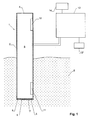
- Fig. 1 shows a sectional view of a first embodiment probe for determining soil moisture content and a block diagram of the circuitry thereof and
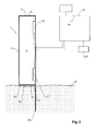
- Fig. 2 is a second embodiment of such a probe.
- The device shown in Fig. 1 comprises a probe 1 having a
tubular housing 2.Tubular housing 2 can e.g. have round or polygonal cross section. It may have constant or varying cross section, and in may in particular also be conical. It has afirst opening 3 at its bottom end and a second opening 4 at its top end and encloses an e.g. cylindrical,elongate chamber 5 extending between both openings. - First opening 3, which is to be embedded into or placed onto the surface of a section of soil 6, can be covered by a permeable barrier 7. In the present embodiment, barrier 7 serves to prevent soil and liquid water from entering
chamber 5 and comprises agrille 8 for mechanical stability and amembrane 9.Membrane 9 is permeable for vapour but not for water.Grille 8 can e.g. be formed by a plurality of bars or a perforated plate arranged at the bottom ofhousing 2. -
Second opening 4 provides a passage fromchamber 5 to ambient air. In the embodiment of Fig. 1 it is not covered by any barrier, but it may also be covered by a barrier (including agrille 8 and/or a membrane 9), in particular for mechanically protecting the interior ofchamber 5, as long as the barrier is permeable for vapour. - Closing second (upper)
opening 4 by a membrane 9 (as it will be shown with reference to the second embodiment of Fig. 2) has been found to increase the measurement accuracy because it shield the humidity sensors from convective motion or drafts of the ambient air, thereby increasing signal accuracy. Also, it prevents water from enteringchamber 5, e.g. during irrigation. - The
membrane 9 used for covering the first and/or second opening is, as mentioned, advantageously made from a material that is permeable for vapour but not for (liquid) water. Advantageously,membrane 9 is of a hydrophobic material, such as polytetrafluoroethylene (PTFE) or PP (polypropylene), having pores in the micro-or nanometer scale. - In the embodiment of Fig. 1, two
humidity sensors chamber 5. They measure the humidity at two spaced-apart locations withinchamber 5. The location monitored byfirst humidity sensor 11 is closer tofirst opening 3 than the location monitored bysecond humidity sensor 12. - The humidity sensors are designed to measure the level of humidity in air. They may e.g. be humidity sensors based on capacitive measurements such as the sensor disclosed in
US 6 690 569 . Each sensor further comprises a temperature sensor. - The humidity and temperature signals from each
sensor control unit 13, which may be mounted in probe 1 or located remotely from the same. In the latter case, the data transfer between probe 1 andcontrol unit 13 may be carried out by means of a wireless or wire-bound communication. - The relative humidity measured by each
sensor Control unit 13 can then compare the two humidities for deriving soil moisture content. - If the soil is dry and in an equilibrium state with the environment, the humidity at both
sensors chamber 5 and a diffusion of humidity takes place. Hence, the humidity atfirst sensor 11 will be larger than the humidity atsecond sensor 12. The difference between the humidities is a measure for the soil moisture content in the soil. Further corrections can be applied to the measured difference, e.g. for compensating temperature-dependent effects. - If the device is used for irrigation control,
control unit 13 can issue an alert for indicating an insufficient soil moisture content. The alert can e.g. be displayed on adisplay 14 and/or be used to initiate an automatic irrigation procedure. - In the embodiment of Fig. 1, both
humidity sensors chamber 5. Alternatively thesecond humidity sensor 12 can also be located to measure the ambient humidity, which can then be used as a reference humidity to be compared to the humidity measured byfirst humidity sensor 11 inchamber 5. - For example,
second humidity sensor 12 can be mounted to the outside of housing 1, or it may be placed at a location remote from probe 1, e.g. together withcontrol unit 13, as indicated by reference numeral 12' in Fig. 1. - If
control unit 13 with its own second humidity sensor 12' is located remote from probe 1, thesame control unit 13 can monitor a plurality of probes 1, each of which comprising a single first humidity sensor only. - The second humidity sensor can be completely dispensed with if it is assumed that ambient humidity is at a fixed level. In that case, the humidity measured by
first humidity sensor 11 alone is sufficient to assess the state of irrigation of the soil, e.g. by comparing the measured humidity to a fixed threshold value. - In the embodiment of Fig. 1,
housing 2 is partially embedded in the soil. Alternatively,housing 2 can be placed outside the soil with itsfirst opening 3 being in contact with the soil surface. Part of the excess moisture in the soil will still enterchamber 5 by diffusion and cause a humidity gradient therein. - In particular if
housing 2 is not to be embedded into the soil but is intended to rest on the surface of the same,first opening 3 can be designed to be larger thansecond opening 4 in order to collect the moisture from a larger area of soil surface and in order to prevent the device from falling over easily. -
Barrier 9 of the shown embodiment consists of two elements, namelygrille 8 andmembrane 9. The functions of these two elements can also be combined into one element, e.g. a sufficiently sturdy membrane. Furthermore,membrane 9 can be dispensed with, e.g. if it is assumed thathumidity sensor 11 will, as a rule, not be below the soil's waterline. Similarly,grille 8 can be dispensed with, e.g. if it is assumed thatsoil entering chamber 5 will not interfere with the operation offirst humidity sensor 11. - Fig. 2 shows an embodiment of the device that is suited for a placement above soil 6. In addition to the embodiment of Fig. 1, it comprises a
fixation member 20, e.g. in the form of a stick, affixed totubular housing 2 and extending beyondfirst opening 3.Fixation member 20 can be embedded in soil 6 for mechanically stabilizing the position of the device with thefirst opening 3 located at the top of the soil. - As can be seen, the
second opening 4 of the device of Fig. 2 is closed by amembrane 9 for improved protection and measurement accuracy as mentioned above. - The positioning of the sensor or sensors within
chamber 5 is fairly flexible. If two sensors are used,second sensor 12 should be on a downstream side (as seen along the diffusion gradient) offirst sensor 11. - The sensors can be placed to communicate with
chamber 5 through ducts, they can be flush with the walls ofchamber 5, or they can project intochamber 5. However, the sensors should be placed such that they do not block the gas exchange betweenfirst opening 3 andsecond opening 4. - It has been found that the sensitivity of the device is increased if
tubular housing 2 is of a material having low thermal conductivity, such as plastics. This is attributed to the fact that a housing with high thermal conductivity tends to equalize the temperatures at the locations of the two humidity sensors, thereby decreasing the humidity concentration gradient. - The soil moisture content can, as mentioned, be determined by comparing the two humidity values measured by the sensors. This comparison can e.g. involve the calculation of the difference between the humidities. The value calculated in this way can then to be compared to a threshold value to yield a Boolean signal indicating if an irrigation is required or not. However, the calculation may also involve any other linear or non-linear function of the two humidities or their difference and may be used to give a more descriptive signal, which can e.g. describe a percentage of humidity remaining in the soil or a time estimate until the soil should be irrigated a next time. Suitable functions can e.g. be derived by calibration measurements.
Claims (15)
- A device for determining soil moisture content comprising a housing (2) and at least a first humidity sensor (11), said device being characterized by
a first opening (3) in said housing (2) to be brought onto or into the soil,
a second opening (4) in said housing (2) to be located outside said soil and
a chamber (5) in said housing (2) extending between said first opening (3) and said second opening (4), said chamber (5) forming a passage for allowing a diffusion of humidity between said first and said second openings (3, 4),
wherein said first humidity sensor (11) is located to measure the humidity at a first location in said chamber (5). - The device of claim 1 wherein said device is adapted to compare a humidity measured by said first humidity sensor (11) to a reference humidity.
- The device of any of the preceding claims further comprising a second humidity sensor (12), wherein said device is adapted to compare the humidities measured by said first and said second humidity sensors (11, 12).
- The device of claim 3 wherein said second humidity sensor (12) is located to measure the humidity at a second location in said chamber (5), which second location is at a larger distance from said first opening (3) than said first location.
- The device of claim 3 wherein said second humidity sensor (12') is located to measure an ambient humidity.
- The device of any of the preceding claims further comprising a temperature sensor, and in particular wherein each humidity sensor (11, 12) comprises a temperature sensor.
- The device of any of the preceding claims further comprising a humidity permeable barrier (7) located at said first opening (3) for preventing an entry of soil into said chamber (5) through said first opening (3).
- The device of any of the preceding claims further comprising a humidity permeable barrier (7) located at said second opening (4) for preventing an entry of soil or liquid water into said chamber (5) through said second opening (4).
- The device of any of the claims 8 or 9 wherein said barrier (7) is permeable for vapour but impermeable for water
- The device of claim 9 wherein said barrier (7) comprises a porous membrane (9) of a hydrophobic material.
- The device of any of the preceding claims wherein said device is adapted to generate a signal indicative of an insufficient soil moisture content.
- The device of any of the preceding claims wherein said housing (2) has tubular shape.
- The device of any of the preceding claims further comprising a fixation member (20) mounted to said housing (2) and extending beyond said first opening (2) for fixing said device in soil with said first opening (2) located at a top of said soil.
- Use of the device of any of the preceding claims for determining soil moisture content.
- Use of claim 14 wherein said device is located on the soil with said first opening (2) located at a top of the soil.
Priority Applications (2)
| Application Number | Priority Date | Filing Date | Title |
|---|---|---|---|
| EP06023094A EP1921449A1 (en) | 2006-11-07 | 2006-11-07 | Device for determining soil moisture content |
| US11/974,095 US20080105035A1 (en) | 2006-11-07 | 2007-10-10 | Device for determining soil moisture content |
Applications Claiming Priority (1)
| Application Number | Priority Date | Filing Date | Title |
|---|---|---|---|
| EP06023094A EP1921449A1 (en) | 2006-11-07 | 2006-11-07 | Device for determining soil moisture content |
Publications (1)
| Publication Number | Publication Date |
|---|---|
| EP1921449A1 true EP1921449A1 (en) | 2008-05-14 |
Family
ID=37806124
Family Applications (1)
| Application Number | Title | Priority Date | Filing Date |
|---|---|---|---|
| EP06023094A Withdrawn EP1921449A1 (en) | 2006-11-07 | 2006-11-07 | Device for determining soil moisture content |
Country Status (2)
| Country | Link |
|---|---|
| US (1) | US20080105035A1 (en) |
| EP (1) | EP1921449A1 (en) |
Cited By (5)
| Publication number | Priority date | Publication date | Assignee | Title |
|---|---|---|---|---|
| DE102008016157A1 (en) * | 2008-03-28 | 2009-10-01 | Fraunhofer-Gesellschaft zur Förderung der angewandten Forschung e.V. | Sensor head for detecting water activity of product, particularly drug product or cosmetic product, has casing which covers interior of gas chamber from outside in fluid-tight manner for partially positioning in product forming casing |
| US20100263436A1 (en) * | 2007-11-01 | 2010-10-21 | Jean Caron | Porous medium sensor |
| US9990172B2 (en) | 2014-12-03 | 2018-06-05 | Sensirion Ag | Wearable electronic device |
| CN110646589A (en) * | 2019-10-14 | 2020-01-03 | 杭州富阳松连食品有限公司 | Novel probe tube for measuring deep soil humidity |
| WO2021244897A1 (en) * | 2020-06-04 | 2021-12-09 | Plantcare Ag | Moisture measuring device having an antibacterial effect |
Families Citing this family (6)
| Publication number | Priority date | Publication date | Assignee | Title |
|---|---|---|---|---|
| CN105699623B (en) * | 2016-03-04 | 2017-08-04 | 华北水利水电大学 | A system and method for dynamic monitoring of soil moisture |
| ES2608901B1 (en) * | 2016-07-20 | 2018-01-26 | Auscultación Y Taller De Ingeniería, S.A. | Improved humidity sensor |
| JP2018126138A (en) * | 2017-02-10 | 2018-08-16 | 国立大学法人九州大学 | Paddy field management system and paddy field management method |
| TWI624656B (en) * | 2017-04-21 | 2018-05-21 | Hou Kuan Lee | Planting environment moisture detection method |
| CN108872326B (en) * | 2017-05-11 | 2021-04-27 | 李厚宽 | Planting environment moisture detection method |
| CN116858927A (en) * | 2022-03-28 | 2023-10-10 | 浙江农林大学 | A soil moisture sensor |
Citations (4)
| Publication number | Priority date | Publication date | Assignee | Title |
|---|---|---|---|---|
| AU664409B2 (en) * | 1992-02-13 | 1995-11-16 | Kenneth James Cuming | An improved soil moisture sensing device |
| WO2000036439A1 (en) * | 1998-12-11 | 2000-06-22 | Bae Systems (Defence Systems) Limited | Convective air temperature and humidity sensor |
| US20060117833A1 (en) * | 2004-12-02 | 2006-06-08 | Construction Technology Laboratories, Inc. | Relative humidity probe for concrete |
| US20060192679A1 (en) | 2005-02-17 | 2006-08-31 | Buckley B S | Plant low water alerting apparatus |
Family Cites Families (7)
| Publication number | Priority date | Publication date | Assignee | Title |
|---|---|---|---|---|
| US4253606A (en) * | 1979-08-30 | 1981-03-03 | Johnson Lonnie G | Automatic sprinkler control |
| US4837499A (en) * | 1986-05-19 | 1989-06-06 | Scherer Iii Robert P | Moisture sensing device |
| US4909070A (en) * | 1987-10-12 | 1990-03-20 | Smith Jeffery B | Moisture sensor |
| US6016971A (en) * | 1996-02-16 | 2000-01-25 | Albert B. Welch | Lawn watering system |
| US20040100394A1 (en) * | 2002-10-28 | 2004-05-27 | Hitt Dale K. | Distributed environmental control in a wireless sensor system |
| US20050090936A1 (en) * | 2003-10-24 | 2005-04-28 | Hitt Dale K. | Two-wire control of sprinkler system |
| EP1571515A1 (en) * | 2004-03-04 | 2005-09-07 | Leica Geosystems AG | Method and apparatus for managing data relative to a worksite area |
-
2006
- 2006-11-07 EP EP06023094A patent/EP1921449A1/en not_active Withdrawn
-
2007
- 2007-10-10 US US11/974,095 patent/US20080105035A1/en not_active Abandoned
Patent Citations (4)
| Publication number | Priority date | Publication date | Assignee | Title |
|---|---|---|---|---|
| AU664409B2 (en) * | 1992-02-13 | 1995-11-16 | Kenneth James Cuming | An improved soil moisture sensing device |
| WO2000036439A1 (en) * | 1998-12-11 | 2000-06-22 | Bae Systems (Defence Systems) Limited | Convective air temperature and humidity sensor |
| US20060117833A1 (en) * | 2004-12-02 | 2006-06-08 | Construction Technology Laboratories, Inc. | Relative humidity probe for concrete |
| US20060192679A1 (en) | 2005-02-17 | 2006-08-31 | Buckley B S | Plant low water alerting apparatus |
Cited By (7)
| Publication number | Priority date | Publication date | Assignee | Title |
|---|---|---|---|---|
| US20100263436A1 (en) * | 2007-11-01 | 2010-10-21 | Jean Caron | Porous medium sensor |
| US8627709B2 (en) * | 2007-11-01 | 2014-01-14 | Hortau Inc. | Porous medium sensor |
| DE102008016157A1 (en) * | 2008-03-28 | 2009-10-01 | Fraunhofer-Gesellschaft zur Förderung der angewandten Forschung e.V. | Sensor head for detecting water activity of product, particularly drug product or cosmetic product, has casing which covers interior of gas chamber from outside in fluid-tight manner for partially positioning in product forming casing |
| DE102008016157B4 (en) * | 2008-03-28 | 2010-02-18 | Fraunhofer-Gesellschaft zur Förderung der angewandten Forschung e.V. | Sensor head for recording the water activity and corresponding measuring method |
| US9990172B2 (en) | 2014-12-03 | 2018-06-05 | Sensirion Ag | Wearable electronic device |
| CN110646589A (en) * | 2019-10-14 | 2020-01-03 | 杭州富阳松连食品有限公司 | Novel probe tube for measuring deep soil humidity |
| WO2021244897A1 (en) * | 2020-06-04 | 2021-12-09 | Plantcare Ag | Moisture measuring device having an antibacterial effect |
Also Published As
| Publication number | Publication date |
|---|---|
| US20080105035A1 (en) | 2008-05-08 |
Similar Documents
| Publication | Publication Date | Title |
|---|---|---|
| US20080105035A1 (en) | Device for determining soil moisture content | |
| Scanlon et al. | 3.2. 4 Miscellaneous methods for measuring matric or water potential | |
| US10364926B2 (en) | Endcap for dry pressure insertion probe | |
| KR950030989A (en) | Analytical Systems for Monitoring Substances Analyzed in Patient Blood | |
| Mullins | Matric potential | |
| US20100326165A1 (en) | Detector test device | |
| US20100053102A1 (en) | Motion sensor data processing and interface and method thereof | |
| PL1785703T3 (en) | Method for monitoring and/or determining the condition of a force measuring device and force measuring device | |
| US6257049B1 (en) | Ambient humidity measurement using microwaves | |
| JP2025116865A (en) | Measuring device for measuring intensive measurands | |
| Malazian et al. | Evaluation of MPS-1 soil water potential sensor | |
| US20220276203A1 (en) | Method and system for determining surface level and soil infiltration under irrigation | |
| KR102241449B1 (en) | Device for measuring transepidermal water loss | |
| CA1070517A (en) | Method and device for determining the pore water pressure in a soil | |
| US7249493B2 (en) | Method and apparatus for measuring relative humidity of a mixture | |
| US9116060B2 (en) | Auto-zeroing absolute pressure sensor | |
| Pavlik et al. | System for testing the hygrothermal performance of multi-layered building envelopes | |
| US7573023B2 (en) | Arrangement and method for compensation of the temperature dependency of detectors in spectrometers | |
| CN111108366A (en) | Soil water potential effector device and its application | |
| KR20220000135A (en) | A apparatus for measuring temperature and humidity for counteracting dry of wet fabric | |
| JP2001349884A (en) | Soil water sampling method and apparatus | |
| Schneider et al. | Novel evaporation experiment to determine soil hydraulic properties | |
| US7059173B2 (en) | System for conducting the on-site measurement of the density or thermal resistance of a material | |
| US7055371B2 (en) | On-site measurement of the density or thermal resistance of a material | |
| US7055370B2 (en) | Device for conducting the on-site measurement of the density or thermal resistance of a material |
Legal Events
| Date | Code | Title | Description |
|---|---|---|---|
| PUAI | Public reference made under article 153(3) epc to a published international application that has entered the european phase |
Free format text: ORIGINAL CODE: 0009012 |
|
| AK | Designated contracting states |
Kind code of ref document: A1 Designated state(s): AT BE BG CH CY CZ DE DK EE ES FI FR GB GR HU IE IS IT LI LT LU LV MC NL PL PT RO SE SI SK TR |
|
| AX | Request for extension of the european patent |
Extension state: AL BA HR MK RS |
|
| RAP1 | Party data changed (applicant data changed or rights of an application transferred) |
Owner name: SENSIRION HOLDING AG |
|
| 17P | Request for examination filed |
Effective date: 20081103 |
|
| AKX | Designation fees paid |
Designated state(s): AT BE BG CH CY CZ DE DK EE ES FI FR GB GR HU IE IS IT LI LT LU LV MC NL PL PT RO SE SI SK TR |
|
| STAA | Information on the status of an ep patent application or granted ep patent |
Free format text: STATUS: THE APPLICATION IS DEEMED TO BE WITHDRAWN |
|
| 18D | Application deemed to be withdrawn |
Effective date: 20100601 |