EP1921381A2 - Combustor and multi combustor including the combustor, and combusting method - Google Patents
Combustor and multi combustor including the combustor, and combusting method Download PDFInfo
- Publication number
- EP1921381A2 EP1921381A2 EP07119676A EP07119676A EP1921381A2 EP 1921381 A2 EP1921381 A2 EP 1921381A2 EP 07119676 A EP07119676 A EP 07119676A EP 07119676 A EP07119676 A EP 07119676A EP 1921381 A2 EP1921381 A2 EP 1921381A2
- Authority
- EP
- European Patent Office
- Prior art keywords
- holes
- jetting
- fuel
- gas
- duct
- Prior art date
- Legal status (The legal status is an assumption and is not a legal conclusion. Google has not performed a legal analysis and makes no representation as to the accuracy of the status listed.)
- Granted
Links
Images


Classifications
-
- F—MECHANICAL ENGINEERING; LIGHTING; HEATING; WEAPONS; BLASTING
- F02—COMBUSTION ENGINES; HOT-GAS OR COMBUSTION-PRODUCT ENGINE PLANTS
- F02C—GAS-TURBINE PLANTS; AIR INTAKES FOR JET-PROPULSION PLANTS; CONTROLLING FUEL SUPPLY IN AIR-BREATHING JET-PROPULSION PLANTS
- F02C9/00—Controlling gas-turbine plants; Controlling fuel supply in air- breathing jet-propulsion plants
- F02C9/26—Control of fuel supply
- F02C9/32—Control of fuel supply characterised by throttling of fuel
-
- F—MECHANICAL ENGINEERING; LIGHTING; HEATING; WEAPONS; BLASTING
- F23—COMBUSTION APPARATUS; COMBUSTION PROCESSES
- F23R—GENERATING COMBUSTION PRODUCTS OF HIGH PRESSURE OR HIGH VELOCITY, e.g. GAS-TURBINE COMBUSTION CHAMBERS
- F23R3/00—Continuous combustion chambers using liquid or gaseous fuel
- F23R3/02—Continuous combustion chambers using liquid or gaseous fuel characterised by the air-flow or gas-flow configuration
- F23R3/04—Air inlet arrangements
- F23R3/10—Air inlet arrangements for primary air
- F23R3/12—Air inlet arrangements for primary air inducing a vortex
- F23R3/14—Air inlet arrangements for primary air inducing a vortex by using swirl vanes
-
- F—MECHANICAL ENGINEERING; LIGHTING; HEATING; WEAPONS; BLASTING
- F02—COMBUSTION ENGINES; HOT-GAS OR COMBUSTION-PRODUCT ENGINE PLANTS
- F02C—GAS-TURBINE PLANTS; AIR INTAKES FOR JET-PROPULSION PLANTS; CONTROLLING FUEL SUPPLY IN AIR-BREATHING JET-PROPULSION PLANTS
- F02C9/00—Controlling gas-turbine plants; Controlling fuel supply in air- breathing jet-propulsion plants
- F02C9/26—Control of fuel supply
- F02C9/38—Control of fuel supply characterised by throttling and returning of fuel to sump
-
- F—MECHANICAL ENGINEERING; LIGHTING; HEATING; WEAPONS; BLASTING
- F23—COMBUSTION APPARATUS; COMBUSTION PROCESSES
- F23C—METHODS OR APPARATUS FOR COMBUSTION USING FLUID FUEL OR SOLID FUEL SUSPENDED IN A CARRIER GAS OR AIR
- F23C7/00—Combustion apparatus characterised by arrangements for air supply
- F23C7/002—Combustion apparatus characterised by arrangements for air supply the air being submitted to a rotary or spinning motion
- F23C7/004—Combustion apparatus characterised by arrangements for air supply the air being submitted to a rotary or spinning motion using vanes
-
- F—MECHANICAL ENGINEERING; LIGHTING; HEATING; WEAPONS; BLASTING
- F23—COMBUSTION APPARATUS; COMBUSTION PROCESSES
- F23D—BURNERS
- F23D14/00—Burners for combustion of a gas, e.g. of a gas stored under pressure as a liquid
- F23D14/46—Details
- F23D14/48—Nozzles
- F23D14/58—Nozzles characterised by the shape or arrangement of the outlet or outlets from the nozzle, e.g. of annular configuration
-
- F—MECHANICAL ENGINEERING; LIGHTING; HEATING; WEAPONS; BLASTING
- F23—COMBUSTION APPARATUS; COMBUSTION PROCESSES
- F23D—BURNERS
- F23D14/00—Burners for combustion of a gas, e.g. of a gas stored under pressure as a liquid
- F23D14/46—Details
- F23D14/60—Devices for simultaneous control of gas and combustion air
-
- F—MECHANICAL ENGINEERING; LIGHTING; HEATING; WEAPONS; BLASTING
- F23—COMBUSTION APPARATUS; COMBUSTION PROCESSES
- F23D—BURNERS
- F23D17/00—Burners for combustion simultaneously or alternately of gaseous or liquid or pulverulent fuel
- F23D17/002—Burners for combustion simultaneously or alternately of gaseous or liquid or pulverulent fuel gaseous or liquid fuel
-
- F—MECHANICAL ENGINEERING; LIGHTING; HEATING; WEAPONS; BLASTING
- F23—COMBUSTION APPARATUS; COMBUSTION PROCESSES
- F23R—GENERATING COMBUSTION PRODUCTS OF HIGH PRESSURE OR HIGH VELOCITY, e.g. GAS-TURBINE COMBUSTION CHAMBERS
- F23R3/00—Continuous combustion chambers using liquid or gaseous fuel
- F23R3/28—Continuous combustion chambers using liquid or gaseous fuel characterised by the fuel supply
- F23R3/286—Continuous combustion chambers using liquid or gaseous fuel characterised by the fuel supply having fuel-air premixing devices
-
- F—MECHANICAL ENGINEERING; LIGHTING; HEATING; WEAPONS; BLASTING
- F23—COMBUSTION APPARATUS; COMBUSTION PROCESSES
- F23R—GENERATING COMBUSTION PRODUCTS OF HIGH PRESSURE OR HIGH VELOCITY, e.g. GAS-TURBINE COMBUSTION CHAMBERS
- F23R3/00—Continuous combustion chambers using liquid or gaseous fuel
- F23R3/28—Continuous combustion chambers using liquid or gaseous fuel characterised by the fuel supply
- F23R3/36—Supply of different fuels
Definitions
- the present invention relates to a dual fuel nozzle of a gas turbine combustor with a variable jetting hole diameter, and more particularly to a dual fuel nozzle of a gas turbine combustor with a variable jetting hole diameter capable of enhancing fuel flexibility in a multiple fuel system for applying two or more fuels to a gas turbine at the same time.
- a dry low NOx gas turbine employs a lean premixed combustion method, wherein a local high-temperature region in the diffusive flame is not generated, thereby suppressing the production of thermal NOx.
- a mass ratio of a fuel amount to an air amount is 10 % or less. It means that the control of the fuel amount is very important. Further, it is very difficult to reach stable combustion conditions of the lean premixed flame. Accordingly, combustion instability, combustion vibration, a backfire of the flame and the like are generated according to a mixing state of fuel and air and load conditions. Thus, there are problems such as damage of gas turbine parts due to abnormal combustion and large pressure variation or heat loss of parts and life reduction due to high-temperature flow (hot gas), thereby causing an increase in the maintenance and repair costs of a gas turbine.
- a natural gas in which methane (CH 4 ) has a volume ratio of 85 % or more or distillate oil serving as a back-up fuel is used as a fuel.
- the fuel has a large range of fluctuation in market prices and a gas turbine capable of applying various power generation fuels thereto should be developed to correspond to the fluctuation range.
- DME dimethyl ether, CH 3 OCH 3
- the DME has combustion characteristics such as a high burning velocity and a low ignition temperature.
- the combustor When the fuel is applied to the gas turbine power plant, the combustor may be burnt out due to the backfire of the flame. Also, a low heating value of the DME, 28.8 MJ/kg (59.3 MJ/Nm 3 ), is lower than a low heating value of a natural gas, which is 49.0 MJ/kg (35.9 MJ/Nm 3 ). Accordingly, it requires retrofitting of the combustor. Further, the combustor should be retrofitted to selectively use the natural gas and the DME fuel.
- a dual fuel type gas turbine using heavy oil and natural gas, which is recently used for power generation, has independent channels which jet the fuel through different fuel jetting holes.
- the power generation cost is expensive and a noxious exhaust gas is largely generated. Accordingly, it is excluded from priority of power generation and the power generation is performed mainly using a natural gas as a fuel.
- a dual fuel nozzle of a gas turbine combustor with a variable jetting hole diameter which includes a plurality of swirling wings disposed along an outer peripheral surface of a central shaft to have at least one main fuel jetting hole; an air duct positioned at the lower side of the swirling wings to supply air to the swirling wings; a pilot fuel injection hole and jetting hole formed to pass through a central portion of the central shaft to supply a pilot fuel; a switching plate disposed inside the swirling wings to vary the size of the main fuel jetting hole; a driving unit disposed to be connected to the switching plate to move a position of the switching plate; and a casing containing the swirling wings, the air duct, the switching plate and the driving unit.
- the main fuel jetting hole is formed in a direction of the central shaft to have a smaller diameter as it goes toward the central shaft.
- At least one switching hole is formed on the switching plate, and the switching hole has a smaller diameter as it goes toward the central shaft.
- the switching holes include first switching holes and second switching holes.
- the first switching holes and the second switching holes are arranged to have different diameters.
- the driving unit includes a rack gear, a spur gear which horizontally moves the rack gear, and a wire which connects the rack gear and the switching plate to vary the position of the switching plate.
- the main fuel jetting hole has a variable diameter according to a supplied fuel. Any one selected from a group consisting of a natural gas, DME (dimethyl ether, CH 3 OCH 3 ), a coal gas and a synthetic gas may be supplied as the varied diameter.
- a liner with at least one plurality of variable dual fuel nozzle.
- a combustor comprising:
- the first holes and the second holes are alternately arranged.
- the first holes and the second holes have gradually increasing sizes from one side to the other side, respectively, and a minimum size of the first holes is different from a minimum size of the second holes.
- the switching member moves in a direction parallel to an arrangement direction of the first holes and the second holes.
- the combustor is disposed at a center of the duct to be parallel to a flowing direction of the gas and further includes a second jetting member which jets a second fuel, and the first jetting member is arranged in a radial shape with respect to the center of the duct and includes a plurality of swirling members which swirl and discharge the gas introduced from a gas introduction hole.
- the first holes and the second holes are arranged on upper surfaces of the swirling members from the center of the duct toward an edge of the duct, and the first holes and the second holes have gradually increasing sizes from the center of the duct toward the edge of the duct, respectively.
- the second jetting member is connected to the first jetting member and includes a first supply line for supplying the first fuel to the first jetting member.
- the combustor further comprises :
- the second jetting member is formed at an upper end of the second jetting member and has second jetting holes which jet the second fuel in a direction equal to a jetting direction of the first jetting member, and the second jetting holes include a central jetting hole arranged on a central shaft of the second jetting member and a plurality of outer jetting holes arranged around the central jetting hole.
- the first fuel is any one of DME (dimethyl ether, CH 3 OCH 3 ), a coal gas and a synthetic gas.
- a multi-combustor system comprising:
- the invention provides a combustion method in which a gas is supplied in one direction and any one of first and second fuels is jetted in the one direction, wherein any one of the first and second fuels is jetted using a plurality of jetting holes formed on a jetting member, and a switching member with first holes and second holes corresponding to the jetting holes is moved such that either ones of the first holes and the second holes are connected to the jetting holes and the other ones are closed.
- the first holes and the second holes have gradually increasing sizes from one side to the other side, respectively, and a minimum size of the first holes is different from a minimum size of the second holes.
- the gas is swirled toward the one direction.
- main fuel injection holes 114 are formed on the swirling wings 110.
- the main fuel injection holes 114 are formed to have a smaller diameter as it goes toward the central shaft 120. Accordingly, it is possible to perform a uniform mixing in relation to the pilot fuel jetted from the central shaft 120.
- the switching plate 130 is disposed at a lower portion of the swirling wings 110.
- the driving unit 140 is disposed to be connected to the switching plate 130, thereby allowing the driving unit 140 to vary a position of the switching plate 130. That is, when a spur gear 144 can be driven by a motor and a rack gear 142 connected to the spur gear 144 can horizontally move, a wire 146 connected at one side of the rack gear 142 moves the switching plate 130. In this case, the wire 146 is moved while being supported by a roller 145.
- a number of switching holes 132 are formed on the switching plate 130.
- the switching holes 132 can have a variable diameter of the main fuel jetting holes 114 when the main fuel is jetted in relation to the main fuel jetting holes 114.
- the main fuel supplied through the main fuel injection holes 122 can be selected variously according to the use conditions of the main fuel. Any one selected from a group consisting of a natural gas, DME (dimethyl ether, CH 3 OCH 3 ), a coal gas and a synthetic gas may be supplied as the main fuel.
- the switching holes 132 are formed to include first switching holes 132a and second switching holes 132b.
- the diameters of the first switching holes 132a and the second switching holes 132b are formed differently from each other.
- the first switching holes 132a and the second switching holes 132b can have different opening diameters of the main fuel jetting holes 114 according to the kinds of the selected main fuel.
- the opening diameters of the main fuel jetting holes 114 are varied by the first switching holes 132a and the second switching holes 132b according to a variable position of the switching plate 130.
- variable dual fuel nozzles 10 is disposed and regularly arranged on a liner 200. That is, the variable dual fuel nozzles are configured by a casing and completed by coupling the casing to the liner.
- the fuel jetting hole designed corresponding to the combustion characteristics improves combustion efficiency and reduces combustion instability while reducing a noxious exhaust gas. Also, it is possible to prevent a backfire of the flame, thereby preventing heat burning out of high-temperature channel parts in the gas turbine.
- the invention is applied to a multi-cup combustor with a number of combustion nozzles and a proper fuel jetting flow rate is set for each cup combustor. Accordingly, in a low nitrogen oxide gas turbine combustor for power generation using a lean premixed combustion method, there are effects of stabilizing a whole flame in the combustor, preventing damage of gas turbine parts by preventing a backfire and reducing combustion vibration, and extending a life.
Landscapes
- Engineering & Computer Science (AREA)
- Chemical & Material Sciences (AREA)
- Combustion & Propulsion (AREA)
- Mechanical Engineering (AREA)
- General Engineering & Computer Science (AREA)
- Combustion Of Fluid Fuel (AREA)
Abstract
Description
- The present invention relates to a dual fuel nozzle of a gas turbine combustor with a variable jetting hole diameter, and more particularly to a dual fuel nozzle of a gas turbine combustor with a variable jetting hole diameter capable of enhancing fuel flexibility in a multiple fuel system for applying two or more fuels to a gas turbine at the same time.
- Recently, development of various clean fuels has been conducted in many research institutions of the world to solve an emission problem of an energy source and an environmental problem. Many fuels such as biomass, a coal gas, GTL (Gas To Liquid Fuel) and CTL (Coal To Liquid Fuel) have been developed and commercialized recently. Also, the research and development have been conducted in a consumption field with the manufacture of the fuels.
- A dry low NOx gas turbine employs a lean premixed combustion method, wherein a local high-temperature region in the diffusive flame is not generated, thereby suppressing the production of thermal NOx.
- However, in the lean premixed combustion method, a mass ratio of a fuel amount to an air amount is 10 % or less. It means that the control of the fuel amount is very important. Further, it is very difficult to reach stable combustion conditions of the lean premixed flame. Accordingly, combustion instability, combustion vibration, a backfire of the flame and the like are generated according to a mixing state of fuel and air and load conditions. Thus, there are problems such as damage of gas turbine parts due to abnormal combustion and large pressure variation or heat loss of parts and life reduction due to high-temperature flow (hot gas), thereby causing an increase in the maintenance and repair costs of a gas turbine.
- Further, conventionally, when the gas turbine is operated at a low load, a noxious gas such as yellow plume caused by NO2 is discharged according to a combustion state. Thus, it may incur the enmity of the people around a power plant.
- Recently, in the power plant using the gas turbine, a natural gas in which methane (CH4) has a volume ratio of 85 % or more or distillate oil serving as a back-up fuel is used as a fuel. However, the fuel has a large range of fluctuation in market prices and a gas turbine capable of applying various power generation fuels thereto should be developed to correspond to the fluctuation range. Particularly, in the future, DME (dimethyl ether, CH3OCH3) which is a new fuel manufactured through a chemical processing method from various fuels such as a natural gas, coal, biomass and the like is expected to be applied after evaluating economical efficiency and technical efficiency. The DME has combustion characteristics such as a high burning velocity and a low ignition temperature. When the fuel is applied to the gas turbine power plant, the combustor may be burnt out due to the backfire of the flame. Also, a low heating value of the DME, 28.8 MJ/kg (59.3 MJ/Nm3), is lower than a low heating value of a natural gas, which is 49.0 MJ/kg (35.9 MJ/Nm3). Accordingly, it requires retrofitting of the combustor. Further, the combustor should be retrofitted to selectively use the natural gas and the DME fuel.
- A dual fuel type gas turbine using heavy oil and natural gas, which is recently used for power generation, has independent channels which jet the fuel through different fuel jetting holes.
- However, in the case of heavy oil power generation, the power generation cost is expensive and a noxious exhaust gas is largely generated. Accordingly, it is excluded from priority of power generation and the power generation is performed mainly using a natural gas as a fuel.
- Therefore, the present invention has been made in view of the above problems, and it is an object of the present invention to provide a multi fuel nozzle of a gas turbine combustor with a variable jetting hole diameter capable of enhancing fuel flexibility in a multiple fuel system for applying two or more fuels to a gas turbine at the same time.
- In accordance with an aspect of the present invention, there is provided a dual fuel nozzle of a gas turbine combustor with a variable jetting hole diameter, which includes a plurality of swirling wings disposed along an outer peripheral surface of a central shaft to have at least one main fuel jetting hole; an air duct positioned at the lower side of the swirling wings to supply air to the swirling wings; a pilot fuel injection hole and jetting hole formed to pass through a central portion of the central shaft to supply a pilot fuel; a switching plate disposed inside the swirling wings to vary the size of the main fuel jetting hole; a driving unit disposed to be connected to the switching plate to move a position of the switching plate; and a casing containing the swirling wings, the air duct, the switching plate and the driving unit.
- Further, the main fuel jetting hole is formed in a direction of the central shaft to have a smaller diameter as it goes toward the central shaft. At least one switching hole is formed on the switching plate, and the switching hole has a smaller diameter as it goes toward the central shaft.
- The switching holes include first switching holes and second switching holes. Preferably, the first switching holes and the second switching holes are arranged to have different diameters.
- Further, the driving unit includes a rack gear, a spur gear which horizontally moves the rack gear, and a wire which connects the rack gear and the switching plate to vary the position of the switching plate. The main fuel jetting hole has a variable diameter according to a supplied fuel. Any one selected from a group consisting of a natural gas, DME (dimethyl ether, CH3OCH3), a coal gas and a synthetic gas may be supplied as the varied diameter.
- Further, there is also provided a liner with at least one plurality of variable dual fuel nozzle.
- In a first aspect of the invention, a combustor is provided, comprising:
- a duct having one side for introducing a gas and the other side for discharging the gas;
- a first jetting member which is installed at the other side of the duct and includes a plurality of first jetting holes for jetting a first fuel; and
- a switching member which is installed on the first jetting holes and includes first holes and second holes corresponding to the first jetting holes;
- Preferably, the first holes and the second holes are alternately arranged.
- Preferably, the first holes and the second holes have gradually increasing sizes from one side to the other side, respectively, and a minimum size of the first holes is different from a minimum size of the second holes.
- Preferably, the switching member moves in a direction parallel to an arrangement direction of the first holes and the second holes.
- Preferably, the combustor is disposed at a center of the duct to be parallel to a flowing direction of the gas and further includes a second jetting member which jets a second fuel, and the first jetting member is arranged in a radial shape with respect to the center of the duct and includes a plurality of swirling members which swirl and discharge the gas introduced from a gas introduction hole.
- Preferably, the first holes and the second holes are arranged on upper surfaces of the swirling members from the center of the duct toward an edge of the duct, and the first holes and the second holes have gradually increasing sizes from the center of the duct toward the edge of the duct, respectively.
- Preferably, the second jetting member is connected to the first jetting member and includes a first supply line for supplying the first fuel to the first jetting member.
- Preferably, the combustor further comprises :
- a wire connected to one end of the switching member to move the switching member;
- a rack gear connected to the other end of the wire to apply tension to the wire along with movement; and
- a spur gear coupled to the rack gear to move the rack gear by rotation.
- Preferably, the second jetting member is formed at an upper end of the second jetting member and has second jetting holes which jet the second fuel in a direction equal to a jetting direction of the first jetting member, and the second jetting holes include a central jetting hole arranged on a central shaft of the second jetting member and a plurality of outer jetting holes arranged around the central jetting hole.
- Preferably, the first fuel is any one of DME (dimethyl ether, CH3OCH3), a coal gas and a synthetic gas.
- In another aspect of the invention, a multi-combustor system is provided, comprising:
- a liner; and
- a plurality of combustors arranged along a center of the liner and a periphery of the liner,
- a duct having a gas introduction hole formed at one side of the duct to introduce a gas and the other side for discharging the gas;
- a plurality of swirling members which are arranged at the other end of the duct in a radial shape with respect to the center of the duct to swirl and discharge the gas introduced from the gas introduction hole and include a plurality of first jetting holes which jet the first fuel;
- a jetting member which is disposed at the center of the duct parallel to a flowing direction of the gas to jet a second fuel and includes a first supply line connected to the swirling members to supply the first fuel to the swirling members;
- a switching member which is installed on the first jetting holes and includes first holes and second holes corresponding to the first jetting holes;
- a wire connected to one end of the switching member to move the switching member;
- a rack gear connected to the other end of the wire to apply tension to the wire along with movement; and
- a spur gear coupled to the rack gear to move the rack gear by rotation,
- In a further aspect, the invention provides a combustion method in which a gas is supplied in one direction and any one of first and second fuels is jetted in the one direction, wherein any one of the first and second fuels is jetted using a plurality of jetting holes formed on a jetting member, and a switching member with first holes and second holes corresponding to the jetting holes is moved such that either ones of the first holes and the second holes are connected to the jetting holes and the other ones are closed.
- Preferably, the first holes and the second holes have gradually increasing sizes from one side to the other side, respectively, and a minimum size of the first holes is different from a minimum size of the second holes.
- Preferably, the gas is swirled toward the one direction.
- The above and other objects, features and other advantages of the present invention will be more clearly understood from the following detailed description taken in conjunction with the accompanying drawings, in which:
- FIG. 1 illustrates a cross-sectional view of a variable dual fuel nozzle according to the present invention;
- FIG. 2 illustrates a plan view of the variable dual fuel nozzle shown in FIG. 1;
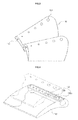
- FIG. 3 illustrates a partial perspective view of swirling wings shown in FIG. 2;
- FIG. 4 illustrates an exploded perspective view of the swirling wings shown in FIG. 3;
- FIGS. 5A and 5B illustrate schematic diagrams showing an operation state of a switching plate; and
- FIG. 6 illustrates a plan view of a variable dual fuel nozzle according to another embodiment of the present invention.
- Hereinafter, an embodiment of the present invention will be described with reference to the accompanying drawings.
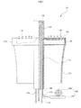
- As shown in FIGS. 1 to 4, a variable
dual fuel nozzle 10 includes swirlingwings 110, acentral shaft 120, aswitching plate 130, adriving unit 140 and acasing 160. - That is, a plurality of swirling
wings 110 is disposed along an outer peripheral surface of an upper portion of thecentral shaft 120. Then, a plurality of main fuel injection holes 122 and a pilotfuel injection hole 124 are disposed at a lower end of thecentral shaft 120 to pass through a central portion of thecentral shaft 120 from a lower portion to an upper portion. A plurality of pilotfuel jetting holes 126 is formed at an upper portion of thecentral shaft 120 to be connected to the pilotfuel injection hole 124. The main fuel injection holes 122 and the swirlingwings 110 are connected to each other using afuel channel 116. In this case, preferably, the main fuel injection holes 122 are formed to have the same number as the number of the swirlingwings 110. Further, the pilotfuel jetting holes 126 are formed along an outer periphery of thecentral shaft 120 to uniformly jet the pilot fuel. - Further, a number of main fuel injection holes 114 are formed on the swirling
wings 110. The main fuel injection holes 114 are formed to have a smaller diameter as it goes toward thecentral shaft 120. Accordingly, it is possible to perform a uniform mixing in relation to the pilot fuel jetted from thecentral shaft 120. - Further, the switching
plate 130 is disposed at a lower portion of the swirlingwings 110. The drivingunit 140 is disposed to be connected to theswitching plate 130, thereby allowing the drivingunit 140 to vary a position of theswitching plate 130. That is, when aspur gear 144 can be driven by a motor and arack gear 142 connected to thespur gear 144 can horizontally move, awire 146 connected at one side of therack gear 142 moves the switchingplate 130. In this case, thewire 146 is moved while being supported by aroller 145. - On the other hand, a number of switching
holes 132 are formed on theswitching plate 130. The switching holes 132 can have a variable diameter of the mainfuel jetting holes 114 when the main fuel is jetted in relation to the main fuel jetting holes 114. Accordingly, the main fuel supplied through the main fuel injection holes 122 can be selected variously according to the use conditions of the main fuel. Any one selected from a group consisting of a natural gas, DME (dimethyl ether, CH3OCH3), a coal gas and a synthetic gas may be supplied as the main fuel. - Further, the switching holes 132 are formed to include
first switching holes 132a and second switching holes 132b. The diameters of thefirst switching holes 132a and the second switching holes 132b are formed differently from each other. Thefirst switching holes 132a and the second switching holes 132b can have different opening diameters of the mainfuel jetting holes 114 according to the kinds of the selected main fuel. - That is, as shown in FIGS. 5A or 5B, the opening diameters of the main
fuel jetting holes 114 are varied by thefirst switching holes 132a and the second switching holes 132b according to a variable position of theswitching plate 130. - Further, air is sucked through an
air duct 112 by the rotation of the swirlingwings 110. The fuel jetted from the pilotfuel jetting holes 126 and the mainfuel jetting holes 114 is mixed with air supplied according to the rotation of the swirlingwings 110 to be jetted into a combustion chamber. - Referring to FIG. 6, according to another embodiment of the present invention, a plurality of variable
dual fuel nozzles 10 is disposed and regularly arranged on aliner 200. That is, the variable dual fuel nozzles are configured by a casing and completed by coupling the casing to the liner. - According to the present invention, there is an effect of enhancing fuel flexibility in a multiple fuel system for applying two or more fuels to a gas turbine at the same time.
- Further, when a fuel is switched in the gas turbine for dual fuel of a natural gas and DME, a fuel switching can be easily made only by performing a button manipulation. Accordingly, it is possible to contribute an increase of fuel flexibility and omit a decomposition operation of the gas turbine for replacement of the combustor. Thus, there is an effect of reducing labor costs and providing a large economic gain due to the reduction of stop time of the gas turbine.
- Further, the fuel jetting hole designed corresponding to the combustion characteristics improves combustion efficiency and reduces combustion instability while reducing a noxious exhaust gas. Also, it is possible to prevent a backfire of the flame, thereby preventing heat burning out of high-temperature channel parts in the gas turbine.
- Further, according to the present invention, the invention is applied to a multi-cup combustor with a number of combustion nozzles and a proper fuel jetting flow rate is set for each cup combustor. Accordingly, in a low nitrogen oxide gas turbine combustor for power generation using a lean premixed combustion method, there are effects of stabilizing a whole flame in the combustor, preventing damage of gas turbine parts by preventing a backfire and reducing combustion vibration, and extending a life.
- Although the preferred embodiment of the present invention has been disclosed for illustrative purposes, those skilled in the art will appreciate that various modifications, additions and substitutions are possible, without departing from the scope and spirit of the invention as disclosed in the accompanying claims.
Claims (14)
- A combustor, comprising:a duct having one side for introducing a gas and the other side for discharging the gas;a first jetting member which is installed at the other side of the duct and includes a plurality of first jetting holes (114) for jetting a first fuel; anda switching member (130) which is installed on the first jetting holes (114) and includes first holes (132a) and second holes (132b) corresponding to the first jetting holes (114) ;wherein either ones of the first holes (132a) and the second holes (132b) are connected to the first jetting holes (114) and the other ones are closed by movement of the switching member (130) .
- The combustor according to claim 1, wherein the first holes (132a) and the second holes (132b) are alternately arranged.
- The combustor according to claim 1, wherein the first holes (132a) and the second holes (132b) have gradually increasing sizes from one side to the other side, respectively, and a minimum size of the first holes (132a) is different from a minimum size of the second holes (132b).
- The combustor according to claim 1, wherein the switching member (130) moves in a direction parallel to an arrangement direction of the first holes (132a) and the second holes (132b).
- The combustor according to claim 1, wherein the combustor is disposed at a center of the duct to be parallel to a flowing direction of the gas and further includes a second jetting member which jets a second fuel, and
the first jetting member is arranged in a radial shape with respect to the center of the duct and includes a plurality of swirling members (110) which swirl and discharge the gas introduced from a gas introduction hole. - The combustor according to claim 5, wherein the first holes (132a) and the second holes (132b) are arranged on upper surfaces of the swirling members (110) from the center of the duct toward an edge of the duct, and the first holes (132a) and the second holes (132b) have gradually increasing sizes from the center of the duct toward the edge of the duct, respectively.
- The combustor according to claim 5, wherein the second jetting member is connected to the first jetting member and includes a first supply line for supplying the first fuel to the first jetting member.
- The combustor according to claim 5, further comprising:a wire (146) connected to one end of the switching member (130) to move the switching member (130) ;a rack gear (142) connected to the other end of the wire (146) to apply tension to the wire (146) along with movement; anda spur gear (144) coupled to the rack gear (142) to move the rack gear (142) by rotation.
- The combustor according to claim 5, wherein the second jetting member is formed at an upper end of the second jetting member and has second jetting holes (126) which jet the second fuel in a direction equal to a jetting direction of the first jetting member, and
the second jetting holes (126) include a central jetting hole arranged on a central shaft of the second jetting member and a plurality of outer jetting holes arranged around the central jetting hole. - The combustor according to claim 1, wherein the first fuel is any one of DME (dimethyl ether, CH3OCH3), a coal gas and a synthetic gas.
- A multi-combustor system, comprising:a liner (200) ; anda plurality of combustors arranged along a center of the liner and a periphery of the liner,wherein each of the combustors includes:a duct having a gas introduction hole formed at one side of the duct to introduce a gas and the other side for discharging the gas;a plurality of swirling members (110) which are arranged at the other end of the duct in a radial shape with respect to the center of the duct to swirl and discharge the gas introduced from the gas introduction hole (122) and include a plurality of first jetting holes (114) which jet the first fuel;a jetting member which is disposed at the center of the duct parallel to a flowing direction of the gas to jet a second fuel and includes a first supply line (116) connected to the swirling members (110) to supply the first fuel to the swirling members (110) ;a switching member (130) which is installed on the first jetting holes and includes first holes (132a) and second holes (132b) corresponding to the first jetting holes (114);a wire (146) connected to one end of the switching member (130) to move the switching member (130) ;a rack gear (142) connected to the other end of the wire (146) to apply tension to the wire (146) along with movement; anda spur gear (144) coupled to the rack gear (142) to move the rack gear (142) by rotation,wherein either ones of the first holes (132a) and the second holes (132b) are connected to the first jetting holes (114) and the other ones are closed by movement of the switching member (130) .
- A combustion method in which a gas is supplied in one direction and any one of first and second fuels is jetted in the one direction, wherein any one of the first and second fuels is jetted using a plurality of jetting holes (114) formed on a jetting member, and a switching member (130) with first holes (132a) and second holes (132b) corresponding to the jetting holes (114) is moved such that either ones of the first holes (132a) and the second holes (132b) are connected to the jetting holes (114) and the other ones are closed.
- The combustion method according to claim 12, wherein the first holes (132a) and the second holes (132b) have gradually increasing sizes from one side to the other side, respectively, and a minimum size of the first holes (132a) is different from a minimum size of the second holes (132b).
- The combustion method according to claim 12, wherein the gas is swirled toward the one direction.
Applications Claiming Priority (1)
| Application Number | Priority Date | Filing Date | Title |
|---|---|---|---|
| KR1020060106423A KR100820233B1 (en) | 2006-10-31 | 2006-10-31 | Combustor, multi combustor including same, and combustion method |
Publications (3)
| Publication Number | Publication Date |
|---|---|
| EP1921381A2 true EP1921381A2 (en) | 2008-05-14 |
| EP1921381A3 EP1921381A3 (en) | 2013-11-27 |
| EP1921381B1 EP1921381B1 (en) | 2017-04-05 |
Family
ID=39092770
Family Applications (1)
| Application Number | Title | Priority Date | Filing Date |
|---|---|---|---|
| EP07119676.0A Active EP1921381B1 (en) | 2006-10-31 | 2007-10-30 | variable jet combustor |
Country Status (4)
| Country | Link |
|---|---|
| US (1) | US8291708B2 (en) |
| EP (1) | EP1921381B1 (en) |
| JP (1) | JP4621722B2 (en) |
| KR (1) | KR100820233B1 (en) |
Cited By (4)
| Publication number | Priority date | Publication date | Assignee | Title |
|---|---|---|---|---|
| US8365534B2 (en) | 2011-03-15 | 2013-02-05 | General Electric Company | Gas turbine combustor having a fuel nozzle for flame anchoring |
| FR3001790A1 (en) * | 2013-02-06 | 2014-08-08 | Gen Electric | VARIABLE VOLUME COMBUSTION CHAMBER WITH FUEL INJECTION SYSTEM UPSTREAM INJECTORS |
| US9500369B2 (en) | 2011-04-21 | 2016-11-22 | General Electric Company | Fuel nozzle and method for operating a combustor |
| EP2345847A3 (en) * | 2010-01-13 | 2017-09-20 | Mitsubishi Hitachi Power Systems, Ltd. | Gas turbine combustor |
Families Citing this family (14)
| Publication number | Priority date | Publication date | Assignee | Title |
|---|---|---|---|---|
| WO2010000709A1 (en) * | 2008-07-02 | 2010-01-07 | Agc Flat Glass Europe Sa | Power supply for hot oxygen burner |
| US20100011770A1 (en) * | 2008-07-21 | 2010-01-21 | Ronald James Chila | Gas Turbine Premixer with Cratered Fuel Injection Sites |
| KR101049359B1 (en) * | 2008-10-31 | 2011-07-13 | 한국전력공사 | Triple swirl gas turbine combustor |
| US20100192582A1 (en) | 2009-02-04 | 2010-08-05 | Robert Bland | Combustor nozzle |
| DE102009045950A1 (en) * | 2009-10-23 | 2011-04-28 | Man Diesel & Turbo Se | swirl generator |
| CN102226533B (en) * | 2011-05-26 | 2012-10-10 | 中国人民解放军国防科学技术大学 | High-speed premixed flame furnace for supersonic burning research |
| US20130174534A1 (en) * | 2012-01-05 | 2013-07-11 | General Electric Company | System and device for controlling fluid flow through a gas turbine exhaust |
| JP6626743B2 (en) * | 2016-03-03 | 2019-12-25 | 三菱重工業株式会社 | Combustion device and gas turbine |
| US10739003B2 (en) * | 2016-10-03 | 2020-08-11 | United Technologies Corporation | Radial fuel shifting and biasing in an axial staged combustor for a gas turbine engine |
| KR102021129B1 (en) * | 2017-10-31 | 2019-11-04 | 두산중공업 주식회사 | Fuel nozzle, combustor and gas turbine having the same |
| KR102044668B1 (en) * | 2018-11-30 | 2019-11-20 | 한국기계연구원 | Gas turbine combustor having nozzle guide for combustion oscillation reduction |
| US12359803B2 (en) * | 2020-07-13 | 2025-07-15 | Gastech Engineering Llc | Cylindrical burner apparatus and method |
| KR102382600B1 (en) | 2020-11-25 | 2022-04-06 | 한국생산기술연구원 | Combined swirl combustor |
| JP2025163523A (en) * | 2024-04-17 | 2025-10-29 | 川崎重工業株式会社 | Burners and Combustors |
Family Cites Families (22)
| Publication number | Priority date | Publication date | Assignee | Title |
|---|---|---|---|---|
| US2458497A (en) * | 1945-05-05 | 1949-01-11 | Babcock & Wilcox Co | Combustion chamber |
| US2993338A (en) * | 1958-04-09 | 1961-07-25 | Gen Motors Corp | Fuel spray bar assembly |
| US3462950A (en) * | 1966-03-28 | 1969-08-26 | Thiokol Chemical Corp | Continuous throttling,slot injection,vortex rocket injector |
| US3991561A (en) * | 1975-06-19 | 1976-11-16 | Curtiss-Wright Corporation | Dual-fuel feed system for a gas turbine engine |
| FR2596102B1 (en) * | 1986-03-20 | 1988-05-27 | Snecma | INJECTION DEVICE WITH AXIAL CENTRIPE |
| US4742685A (en) * | 1986-11-04 | 1988-05-10 | Ex-Cell-O Corporation | Fuel distributing and metering assembly |
| DE4000446A1 (en) * | 1990-01-09 | 1991-07-11 | Siemens Ag | FITTING FOR CONNECTING AT LEAST ONE HYBRID BURNER WITH DEVICES FOR DELIVERING A FLUIDIC FUEL |
| EP0580683B1 (en) * | 1991-04-25 | 1995-11-08 | Siemens Aktiengesellschaft | Burner arrangement, especially for gas turbines, for the low-pollutant combustion of coal gas and other fuels |
| US5351477A (en) | 1993-12-21 | 1994-10-04 | General Electric Company | Dual fuel mixer for gas turbine combustor |
| EP0747635B1 (en) * | 1995-06-05 | 2003-01-15 | Rolls-Royce Corporation | Dry low oxides of nitrogen lean premix module for industrial gas turbine engines |
| US6123273A (en) * | 1997-09-30 | 2000-09-26 | General Electric Co. | Dual-fuel nozzle for inhibiting carbon deposition onto combustor surfaces in a gas turbine |
| DE69941535D1 (en) * | 1998-12-18 | 2009-11-26 | Panasonic Corp | CATALYTIC COMBUSTION DEVICE |
| JP3457907B2 (en) | 1998-12-24 | 2003-10-20 | 三菱重工業株式会社 | Dual fuel nozzle |
| JP2001065810A (en) * | 1999-08-25 | 2001-03-16 | Nkk Corp | Combustion burner combustion method |
| JP2001227711A (en) * | 2000-02-17 | 2001-08-24 | Tokyo Gas Co Ltd | Low NOx burner |
| JP2001249721A (en) * | 2000-03-06 | 2001-09-14 | Mitsubishi Heavy Ind Ltd | Device for varying flow rate of fluid |
| JP2002213746A (en) | 2001-01-19 | 2002-07-31 | Mitsubishi Heavy Ind Ltd | Burner, premix fuel nozzle of combustor, and an combustor |
| US6928823B2 (en) * | 2001-08-29 | 2005-08-16 | Hitachi, Ltd. | Gas turbine combustor and operating method thereof |
| EP1394471A1 (en) * | 2002-09-02 | 2004-03-03 | Siemens Aktiengesellschaft | Burner |
| US6832481B2 (en) | 2002-09-26 | 2004-12-21 | Siemens Westinghouse Power Corporation | Turbine engine fuel nozzle |
| EP1507119A1 (en) * | 2003-08-13 | 2005-02-16 | Siemens Aktiengesellschaft | Burner and process to operate a gas turbine |
| US7377036B2 (en) | 2004-10-05 | 2008-05-27 | General Electric Company | Methods for tuning fuel injection assemblies for a gas turbine fuel nozzle |
-
2006
- 2006-10-31 KR KR1020060106423A patent/KR100820233B1/en active Active
-
2007
- 2007-10-30 US US11/928,522 patent/US8291708B2/en not_active Expired - Fee Related
- 2007-10-30 JP JP2007281788A patent/JP4621722B2/en active Active
- 2007-10-30 EP EP07119676.0A patent/EP1921381B1/en active Active
Cited By (4)
| Publication number | Priority date | Publication date | Assignee | Title |
|---|---|---|---|---|
| EP2345847A3 (en) * | 2010-01-13 | 2017-09-20 | Mitsubishi Hitachi Power Systems, Ltd. | Gas turbine combustor |
| US8365534B2 (en) | 2011-03-15 | 2013-02-05 | General Electric Company | Gas turbine combustor having a fuel nozzle for flame anchoring |
| US9500369B2 (en) | 2011-04-21 | 2016-11-22 | General Electric Company | Fuel nozzle and method for operating a combustor |
| FR3001790A1 (en) * | 2013-02-06 | 2014-08-08 | Gen Electric | VARIABLE VOLUME COMBUSTION CHAMBER WITH FUEL INJECTION SYSTEM UPSTREAM INJECTORS |
Also Published As
| Publication number | Publication date |
|---|---|
| JP4621722B2 (en) | 2011-01-26 |
| KR100820233B1 (en) | 2008-04-08 |
| EP1921381A3 (en) | 2013-11-27 |
| US20080098736A1 (en) | 2008-05-01 |
| JP2008116200A (en) | 2008-05-22 |
| EP1921381B1 (en) | 2017-04-05 |
| US8291708B2 (en) | 2012-10-23 |
Similar Documents
| Publication | Publication Date | Title |
|---|---|---|
| EP1921381B1 (en) | variable jet combustor | |
| EP2423600B1 (en) | Gas turbine combustor | |
| EP3519733B1 (en) | Swirler, combustor assembly, and gas turbine with improved fuel/air mixing | |
| EP2525148B1 (en) | A combustor nozzle and method for supplying fuel to a combustor | |
| JP6196868B2 (en) | Fuel nozzle and its assembly method | |
| EP2251605A2 (en) | Dry low nox combustion system with pre-mixed direct-injection secondary fuel-nozzle | |
| EP2206958A2 (en) | Method and apparatus for fuel injection in a turbine engine | |
| EP2458283B1 (en) | Gas turbine combustor and fuel supply method used for the same | |
| CN101929678A (en) | Multiple fuel circuits for syngas/NG DLN in premix nozzles | |
| CA2773943A1 (en) | Inlet premixer for combustion apparatus | |
| CN204923077U (en) | Multi -jet spray nozzle and be equipped with gas turbine of this nozzle | |
| CN106678875A (en) | Main-combustion-level low-emission combustion chamber adopting fuel injection tube in fuel supply | |
| JP6474951B2 (en) | Combustor | |
| CN108592083B (en) | Combustion chamber adopting variable cross-section air inlet and multi-stage fuel supply and control method thereof | |
| KR20100048555A (en) | Triple swirl gas turbine combustor | |
| CN102635860A (en) | System and method for operating a combustor | |
| US11708973B2 (en) | Combustor | |
| CN108332234B (en) | Multi-fuel-adaptive combustion chamber and multi-stage fuel supply premixing and control method | |
| JP7270517B2 (en) | gas turbine combustor | |
| CN104315541A (en) | Duty-stage spray nozzle of combustion chamber and use method of spray nozzle | |
| CN113776086B (en) | Low-pollution combustion chamber nozzle structure and method | |
| CN204717744U (en) | A kind of nozzle of radial spray and be provided with the gas turbine of this nozzle | |
| CN102635861A (en) | System and method for operating a combustor | |
| CN1987204A (en) | Hot gas machine burner | |
| Soudarev et al. | Results of Environmental Retrofit for Gas Pipeline Gas-Pumping Units |
Legal Events
| Date | Code | Title | Description |
|---|---|---|---|
| PUAI | Public reference made under article 153(3) epc to a published international application that has entered the european phase |
Free format text: ORIGINAL CODE: 0009012 |
|
| AK | Designated contracting states |
Kind code of ref document: A2 Designated state(s): AT BE BG CH CY CZ DE DK EE ES FI FR GB GR HU IE IS IT LI LT LU LV MC MT NL PL PT RO SE SI SK TR |
|
| AX | Request for extension of the european patent |
Extension state: AL BA HR MK RS |
|
| PUAL | Search report despatched |
Free format text: ORIGINAL CODE: 0009013 |
|
| AK | Designated contracting states |
Kind code of ref document: A3 Designated state(s): AT BE BG CH CY CZ DE DK EE ES FI FR GB GR HU IE IS IT LI LT LU LV MC MT NL PL PT RO SE SI SK TR |
|
| AX | Request for extension of the european patent |
Extension state: AL BA HR MK RS |
|
| RIC1 | Information provided on ipc code assigned before grant |
Ipc: F23R 3/36 20060101ALI20131024BHEP Ipc: F23D 14/58 20060101ALI20131024BHEP Ipc: F23C 7/00 20060101ALI20131024BHEP Ipc: F23R 3/28 20060101ALI20131024BHEP Ipc: F23D 14/60 20060101ALI20131024BHEP Ipc: F23R 3/14 20060101AFI20131024BHEP Ipc: F23D 17/00 20060101ALI20131024BHEP |
|
| 17P | Request for examination filed |
Effective date: 20140526 |
|
| RBV | Designated contracting states (corrected) |
Designated state(s): AT BE BG CH CY CZ DE DK EE ES FI FR GB GR HU IE IS IT LI LT LU LV MC MT NL PL PT RO SE SI SK TR |
|
| AKX | Designation fees paid |
Designated state(s): AT BE BG CH CY CZ DE DK EE ES FI FR GB GR HU IE IS IT LI LT LU LV MC MT NL PL PT RO SE SI SK TR |
|
| GRAP | Despatch of communication of intention to grant a patent |
Free format text: ORIGINAL CODE: EPIDOSNIGR1 |
|
| INTG | Intention to grant announced |
Effective date: 20161025 |
|
| GRAS | Grant fee paid |
Free format text: ORIGINAL CODE: EPIDOSNIGR3 |
|
| GRAA | (expected) grant |
Free format text: ORIGINAL CODE: 0009210 |
|
| AK | Designated contracting states |
Kind code of ref document: B1 Designated state(s): AT BE BG CH CY CZ DE DK EE ES FI FR GB GR HU IE IS IT LI LT LU LV MC MT NL PL PT RO SE SI SK TR |
|
| REG | Reference to a national code |
Ref country code: GB Ref legal event code: FG4D |
|
| REG | Reference to a national code |
Ref country code: CH Ref legal event code: EP |
|
| REG | Reference to a national code |
Ref country code: AT Ref legal event code: REF Ref document number: 882182 Country of ref document: AT Kind code of ref document: T Effective date: 20170415 |
|
| REG | Reference to a national code |
Ref country code: IE Ref legal event code: FG4D |
|
| REG | Reference to a national code |
Ref country code: DE Ref legal event code: R096 Ref document number: 602007050457 Country of ref document: DE |
|
| REG | Reference to a national code |
Ref country code: NL Ref legal event code: MP Effective date: 20170405 |
|
| REG | Reference to a national code |
Ref country code: LT Ref legal event code: MG4D |
|
| REG | Reference to a national code |
Ref country code: AT Ref legal event code: MK05 Ref document number: 882182 Country of ref document: AT Kind code of ref document: T Effective date: 20170405 |
|
| PG25 | Lapsed in a contracting state [announced via postgrant information from national office to epo] |
Ref country code: NL Free format text: LAPSE BECAUSE OF FAILURE TO SUBMIT A TRANSLATION OF THE DESCRIPTION OR TO PAY THE FEE WITHIN THE PRESCRIBED TIME-LIMIT Effective date: 20170405 |
|
| PG25 | Lapsed in a contracting state [announced via postgrant information from national office to epo] |
Ref country code: FI Free format text: LAPSE BECAUSE OF FAILURE TO SUBMIT A TRANSLATION OF THE DESCRIPTION OR TO PAY THE FEE WITHIN THE PRESCRIBED TIME-LIMIT Effective date: 20170405 Ref country code: GR Free format text: LAPSE BECAUSE OF FAILURE TO SUBMIT A TRANSLATION OF THE DESCRIPTION OR TO PAY THE FEE WITHIN THE PRESCRIBED TIME-LIMIT Effective date: 20170706 Ref country code: LT Free format text: LAPSE BECAUSE OF FAILURE TO SUBMIT A TRANSLATION OF THE DESCRIPTION OR TO PAY THE FEE WITHIN THE PRESCRIBED TIME-LIMIT Effective date: 20170405 Ref country code: AT Free format text: LAPSE BECAUSE OF FAILURE TO SUBMIT A TRANSLATION OF THE DESCRIPTION OR TO PAY THE FEE WITHIN THE PRESCRIBED TIME-LIMIT Effective date: 20170405 Ref country code: ES Free format text: LAPSE BECAUSE OF FAILURE TO SUBMIT A TRANSLATION OF THE DESCRIPTION OR TO PAY THE FEE WITHIN THE PRESCRIBED TIME-LIMIT Effective date: 20170405 |
|
| PG25 | Lapsed in a contracting state [announced via postgrant information from national office to epo] |
Ref country code: IS Free format text: LAPSE BECAUSE OF FAILURE TO SUBMIT A TRANSLATION OF THE DESCRIPTION OR TO PAY THE FEE WITHIN THE PRESCRIBED TIME-LIMIT Effective date: 20170805 Ref country code: LV Free format text: LAPSE BECAUSE OF FAILURE TO SUBMIT A TRANSLATION OF THE DESCRIPTION OR TO PAY THE FEE WITHIN THE PRESCRIBED TIME-LIMIT Effective date: 20170405 Ref country code: BG Free format text: LAPSE BECAUSE OF FAILURE TO SUBMIT A TRANSLATION OF THE DESCRIPTION OR TO PAY THE FEE WITHIN THE PRESCRIBED TIME-LIMIT Effective date: 20170705 Ref country code: PL Free format text: LAPSE BECAUSE OF FAILURE TO SUBMIT A TRANSLATION OF THE DESCRIPTION OR TO PAY THE FEE WITHIN THE PRESCRIBED TIME-LIMIT Effective date: 20170405 Ref country code: SE Free format text: LAPSE BECAUSE OF FAILURE TO SUBMIT A TRANSLATION OF THE DESCRIPTION OR TO PAY THE FEE WITHIN THE PRESCRIBED TIME-LIMIT Effective date: 20170405 |
|
| REG | Reference to a national code |
Ref country code: DE Ref legal event code: R097 Ref document number: 602007050457 Country of ref document: DE |
|
| PG25 | Lapsed in a contracting state [announced via postgrant information from national office to epo] |
Ref country code: DK Free format text: LAPSE BECAUSE OF FAILURE TO SUBMIT A TRANSLATION OF THE DESCRIPTION OR TO PAY THE FEE WITHIN THE PRESCRIBED TIME-LIMIT Effective date: 20170405 Ref country code: EE Free format text: LAPSE BECAUSE OF FAILURE TO SUBMIT A TRANSLATION OF THE DESCRIPTION OR TO PAY THE FEE WITHIN THE PRESCRIBED TIME-LIMIT Effective date: 20170405 Ref country code: CZ Free format text: LAPSE BECAUSE OF FAILURE TO SUBMIT A TRANSLATION OF THE DESCRIPTION OR TO PAY THE FEE WITHIN THE PRESCRIBED TIME-LIMIT Effective date: 20170405 Ref country code: RO Free format text: LAPSE BECAUSE OF FAILURE TO SUBMIT A TRANSLATION OF THE DESCRIPTION OR TO PAY THE FEE WITHIN THE PRESCRIBED TIME-LIMIT Effective date: 20170405 Ref country code: SK Free format text: LAPSE BECAUSE OF FAILURE TO SUBMIT A TRANSLATION OF THE DESCRIPTION OR TO PAY THE FEE WITHIN THE PRESCRIBED TIME-LIMIT Effective date: 20170405 |
|
| PLBE | No opposition filed within time limit |
Free format text: ORIGINAL CODE: 0009261 |
|
| STAA | Information on the status of an ep patent application or granted ep patent |
Free format text: STATUS: NO OPPOSITION FILED WITHIN TIME LIMIT |
|
| PG25 | Lapsed in a contracting state [announced via postgrant information from national office to epo] |
Ref country code: IT Free format text: LAPSE BECAUSE OF FAILURE TO SUBMIT A TRANSLATION OF THE DESCRIPTION OR TO PAY THE FEE WITHIN THE PRESCRIBED TIME-LIMIT Effective date: 20170405 |
|
| 26N | No opposition filed |
Effective date: 20180108 |
|
| PG25 | Lapsed in a contracting state [announced via postgrant information from national office to epo] |
Ref country code: SI Free format text: LAPSE BECAUSE OF FAILURE TO SUBMIT A TRANSLATION OF THE DESCRIPTION OR TO PAY THE FEE WITHIN THE PRESCRIBED TIME-LIMIT Effective date: 20170405 Ref country code: MC Free format text: LAPSE BECAUSE OF FAILURE TO SUBMIT A TRANSLATION OF THE DESCRIPTION OR TO PAY THE FEE WITHIN THE PRESCRIBED TIME-LIMIT Effective date: 20170405 |
|
| REG | Reference to a national code |
Ref country code: CH Ref legal event code: PL |
|
| GBPC | Gb: european patent ceased through non-payment of renewal fee |
Effective date: 20171030 |
|
| REG | Reference to a national code |
Ref country code: IE Ref legal event code: MM4A |
|
| REG | Reference to a national code |
Ref country code: FR Ref legal event code: ST Effective date: 20180629 |
|
| PG25 | Lapsed in a contracting state [announced via postgrant information from national office to epo] |
Ref country code: GB Free format text: LAPSE BECAUSE OF NON-PAYMENT OF DUE FEES Effective date: 20171030 Ref country code: LU Free format text: LAPSE BECAUSE OF NON-PAYMENT OF DUE FEES Effective date: 20171030 Ref country code: CH Free format text: LAPSE BECAUSE OF NON-PAYMENT OF DUE FEES Effective date: 20171031 Ref country code: LI Free format text: LAPSE BECAUSE OF NON-PAYMENT OF DUE FEES Effective date: 20171031 |
|
| REG | Reference to a national code |
Ref country code: BE Ref legal event code: MM Effective date: 20171031 |
|
| PG25 | Lapsed in a contracting state [announced via postgrant information from national office to epo] |
Ref country code: FR Free format text: LAPSE BECAUSE OF NON-PAYMENT OF DUE FEES Effective date: 20171031 Ref country code: BE Free format text: LAPSE BECAUSE OF NON-PAYMENT OF DUE FEES Effective date: 20171031 |
|
| PG25 | Lapsed in a contracting state [announced via postgrant information from national office to epo] |
Ref country code: MT Free format text: LAPSE BECAUSE OF NON-PAYMENT OF DUE FEES Effective date: 20171030 |
|
| PG25 | Lapsed in a contracting state [announced via postgrant information from national office to epo] |
Ref country code: IE Free format text: LAPSE BECAUSE OF NON-PAYMENT OF DUE FEES Effective date: 20171030 |
|
| PG25 | Lapsed in a contracting state [announced via postgrant information from national office to epo] |
Ref country code: HU Free format text: LAPSE BECAUSE OF FAILURE TO SUBMIT A TRANSLATION OF THE DESCRIPTION OR TO PAY THE FEE WITHIN THE PRESCRIBED TIME-LIMIT; INVALID AB INITIO Effective date: 20071030 |
|
| PG25 | Lapsed in a contracting state [announced via postgrant information from national office to epo] |
Ref country code: CY Free format text: LAPSE BECAUSE OF NON-PAYMENT OF DUE FEES Effective date: 20170405 |
|
| PG25 | Lapsed in a contracting state [announced via postgrant information from national office to epo] |
Ref country code: TR Free format text: LAPSE BECAUSE OF FAILURE TO SUBMIT A TRANSLATION OF THE DESCRIPTION OR TO PAY THE FEE WITHIN THE PRESCRIBED TIME-LIMIT Effective date: 20170405 |
|
| PG25 | Lapsed in a contracting state [announced via postgrant information from national office to epo] |
Ref country code: PT Free format text: LAPSE BECAUSE OF FAILURE TO SUBMIT A TRANSLATION OF THE DESCRIPTION OR TO PAY THE FEE WITHIN THE PRESCRIBED TIME-LIMIT Effective date: 20170405 |
|
| PGFP | Annual fee paid to national office [announced via postgrant information from national office to epo] |
Ref country code: DE Payment date: 20251027 Year of fee payment: 19 |