EP1921321A1 - Cross-flow fan made of resin and method of manufacturing the same - Google Patents
Cross-flow fan made of resin and method of manufacturing the same Download PDFInfo
- Publication number
- EP1921321A1 EP1921321A1 EP06782080A EP06782080A EP1921321A1 EP 1921321 A1 EP1921321 A1 EP 1921321A1 EP 06782080 A EP06782080 A EP 06782080A EP 06782080 A EP06782080 A EP 06782080A EP 1921321 A1 EP1921321 A1 EP 1921321A1
- Authority
- EP
- European Patent Office
- Prior art keywords
- blades
- portions
- flow fan
- cross flow
- projecting portions
- Prior art date
- Legal status (The legal status is an assumption and is not a legal conclusion. Google has not performed a legal analysis and makes no representation as to the accuracy of the status listed.)
- Withdrawn
Links
Images




Classifications
-
- F—MECHANICAL ENGINEERING; LIGHTING; HEATING; WEAPONS; BLASTING
- F04—POSITIVE - DISPLACEMENT MACHINES FOR LIQUIDS; PUMPS FOR LIQUIDS OR ELASTIC FLUIDS
- F04D—NON-POSITIVE-DISPLACEMENT PUMPS
- F04D29/00—Details, component parts, or accessories
- F04D29/26—Rotors specially for elastic fluids
- F04D29/28—Rotors specially for elastic fluids for centrifugal or helico-centrifugal pumps for radial-flow or helico-centrifugal pumps
- F04D29/281—Rotors specially for elastic fluids for centrifugal or helico-centrifugal pumps for radial-flow or helico-centrifugal pumps for fans or blowers
- F04D29/282—Rotors specially for elastic fluids for centrifugal or helico-centrifugal pumps for radial-flow or helico-centrifugal pumps for fans or blowers the leading edge of each vane being substantially parallel to the rotation axis
- F04D29/283—Rotors specially for elastic fluids for centrifugal or helico-centrifugal pumps for radial-flow or helico-centrifugal pumps for fans or blowers the leading edge of each vane being substantially parallel to the rotation axis rotors of the squirrel-cage type
-
- F—MECHANICAL ENGINEERING; LIGHTING; HEATING; WEAPONS; BLASTING
- F04—POSITIVE - DISPLACEMENT MACHINES FOR LIQUIDS; PUMPS FOR LIQUIDS OR ELASTIC FLUIDS
- F04D—NON-POSITIVE-DISPLACEMENT PUMPS
- F04D17/00—Radial-flow pumps, e.g. centrifugal pumps; Helico-centrifugal pumps
- F04D17/02—Radial-flow pumps, e.g. centrifugal pumps; Helico-centrifugal pumps having non-centrifugal stages, e.g. centripetal
- F04D17/04—Radial-flow pumps, e.g. centrifugal pumps; Helico-centrifugal pumps having non-centrifugal stages, e.g. centripetal of transverse-flow type
-
- F—MECHANICAL ENGINEERING; LIGHTING; HEATING; WEAPONS; BLASTING
- F04—POSITIVE - DISPLACEMENT MACHINES FOR LIQUIDS; PUMPS FOR LIQUIDS OR ELASTIC FLUIDS
- F04D—NON-POSITIVE-DISPLACEMENT PUMPS
- F04D29/00—Details, component parts, or accessories
- F04D29/02—Selection of particular materials
- F04D29/023—Selection of particular materials especially adapted for elastic fluid pumps
-
- F—MECHANICAL ENGINEERING; LIGHTING; HEATING; WEAPONS; BLASTING
- F04—POSITIVE - DISPLACEMENT MACHINES FOR LIQUIDS; PUMPS FOR LIQUIDS OR ELASTIC FLUIDS
- F04D—NON-POSITIVE-DISPLACEMENT PUMPS
- F04D29/00—Details, component parts, or accessories
- F04D29/26—Rotors specially for elastic fluids
- F04D29/32—Rotors specially for elastic fluids for axial flow pumps
- F04D29/38—Blades
-
- B—PERFORMING OPERATIONS; TRANSPORTING
- B29—WORKING OF PLASTICS; WORKING OF SUBSTANCES IN A PLASTIC STATE IN GENERAL
- B29C—SHAPING OR JOINING OF PLASTICS; SHAPING OF MATERIAL IN A PLASTIC STATE, NOT OTHERWISE PROVIDED FOR; AFTER-TREATMENT OF THE SHAPED PRODUCTS, e.g. REPAIRING
- B29C65/00—Joining or sealing of preformed parts, e.g. welding of plastics materials; Apparatus therefor
- B29C65/02—Joining or sealing of preformed parts, e.g. welding of plastics materials; Apparatus therefor by heating, with or without pressure
- B29C65/14—Joining or sealing of preformed parts, e.g. welding of plastics materials; Apparatus therefor by heating, with or without pressure using wave energy, i.e. electromagnetic radiation, or particle radiation
- B29C65/16—Laser beams
- B29C65/1629—Laser beams characterised by the way of heating the interface
- B29C65/1635—Laser beams characterised by the way of heating the interface at least passing through one of the parts to be joined, i.e. laser transmission welding
-
- B—PERFORMING OPERATIONS; TRANSPORTING
- B29—WORKING OF PLASTICS; WORKING OF SUBSTANCES IN A PLASTIC STATE IN GENERAL
- B29C—SHAPING OR JOINING OF PLASTICS; SHAPING OF MATERIAL IN A PLASTIC STATE, NOT OTHERWISE PROVIDED FOR; AFTER-TREATMENT OF THE SHAPED PRODUCTS, e.g. REPAIRING
- B29C66/00—General aspects of processes or apparatus for joining preformed parts
- B29C66/50—General aspects of joining tubular articles; General aspects of joining long products, i.e. bars or profiled elements; General aspects of joining single elements to tubular articles, hollow articles or bars; General aspects of joining several hollow-preforms to form hollow or tubular articles
- B29C66/51—Joining tubular articles, profiled elements or bars; Joining single elements to tubular articles, hollow articles or bars; Joining several hollow-preforms to form hollow or tubular articles
- B29C66/53—Joining single elements to tubular articles, hollow articles or bars
- B29C66/534—Joining single elements to open ends of tubular or hollow articles or to the ends of bars
- B29C66/5344—Joining single elements to open ends of tubular or hollow articles or to the ends of bars said single elements being substantially annular, i.e. of finite length, e.g. joining flanges to tube ends
-
- B—PERFORMING OPERATIONS; TRANSPORTING
- B29—WORKING OF PLASTICS; WORKING OF SUBSTANCES IN A PLASTIC STATE IN GENERAL
- B29C—SHAPING OR JOINING OF PLASTICS; SHAPING OF MATERIAL IN A PLASTIC STATE, NOT OTHERWISE PROVIDED FOR; AFTER-TREATMENT OF THE SHAPED PRODUCTS, e.g. REPAIRING
- B29C66/00—General aspects of processes or apparatus for joining preformed parts
- B29C66/50—General aspects of joining tubular articles; General aspects of joining long products, i.e. bars or profiled elements; General aspects of joining single elements to tubular articles, hollow articles or bars; General aspects of joining several hollow-preforms to form hollow or tubular articles
- B29C66/51—Joining tubular articles, profiled elements or bars; Joining single elements to tubular articles, hollow articles or bars; Joining several hollow-preforms to form hollow or tubular articles
- B29C66/53—Joining single elements to tubular articles, hollow articles or bars
- B29C66/534—Joining single elements to open ends of tubular or hollow articles or to the ends of bars
- B29C66/5346—Joining single elements to open ends of tubular or hollow articles or to the ends of bars said single elements being substantially flat
-
- B—PERFORMING OPERATIONS; TRANSPORTING
- B29—WORKING OF PLASTICS; WORKING OF SUBSTANCES IN A PLASTIC STATE IN GENERAL
- B29C—SHAPING OR JOINING OF PLASTICS; SHAPING OF MATERIAL IN A PLASTIC STATE, NOT OTHERWISE PROVIDED FOR; AFTER-TREATMENT OF THE SHAPED PRODUCTS, e.g. REPAIRING
- B29C66/00—General aspects of processes or apparatus for joining preformed parts
- B29C66/50—General aspects of joining tubular articles; General aspects of joining long products, i.e. bars or profiled elements; General aspects of joining single elements to tubular articles, hollow articles or bars; General aspects of joining several hollow-preforms to form hollow or tubular articles
- B29C66/51—Joining tubular articles, profiled elements or bars; Joining single elements to tubular articles, hollow articles or bars; Joining several hollow-preforms to form hollow or tubular articles
- B29C66/54—Joining several hollow-preforms, e.g. half-shells, to form hollow articles, e.g. for making balls, containers; Joining several hollow-preforms, e.g. half-cylinders, to form tubular articles
- B29C66/543—Joining several hollow-preforms, e.g. half-shells, to form hollow articles, e.g. for making balls, containers; Joining several hollow-preforms, e.g. half-cylinders, to form tubular articles joining more than two hollow-preforms to form said hollow articles
-
- B—PERFORMING OPERATIONS; TRANSPORTING
- B29—WORKING OF PLASTICS; WORKING OF SUBSTANCES IN A PLASTIC STATE IN GENERAL
- B29L—INDEXING SCHEME ASSOCIATED WITH SUBCLASS B29C, RELATING TO PARTICULAR ARTICLES
- B29L2031/00—Other particular articles
- B29L2031/08—Blades for rotors, stators, fans, turbines or the like, e.g. screw propellers
-
- F—MECHANICAL ENGINEERING; LIGHTING; HEATING; WEAPONS; BLASTING
- F05—INDEXING SCHEMES RELATING TO ENGINES OR PUMPS IN VARIOUS SUBCLASSES OF CLASSES F01-F04
- F05D—INDEXING SCHEME FOR ASPECTS RELATING TO NON-POSITIVE-DISPLACEMENT MACHINES OR ENGINES, GAS-TURBINES OR JET-PROPULSION PLANTS
- F05D2230/00—Manufacture
- F05D2230/20—Manufacture essentially without removing material
- F05D2230/23—Manufacture essentially without removing material by permanently joining parts together
- F05D2230/232—Manufacture essentially without removing material by permanently joining parts together by welding
- F05D2230/234—Laser welding
-
- F—MECHANICAL ENGINEERING; LIGHTING; HEATING; WEAPONS; BLASTING
- F05—INDEXING SCHEMES RELATING TO ENGINES OR PUMPS IN VARIOUS SUBCLASSES OF CLASSES F01-F04
- F05D—INDEXING SCHEME FOR ASPECTS RELATING TO NON-POSITIVE-DISPLACEMENT MACHINES OR ENGINES, GAS-TURBINES OR JET-PROPULSION PLANTS
- F05D2300/00—Materials; Properties thereof
- F05D2300/40—Organic materials
- F05D2300/44—Resins
-
- Y—GENERAL TAGGING OF NEW TECHNOLOGICAL DEVELOPMENTS; GENERAL TAGGING OF CROSS-SECTIONAL TECHNOLOGIES SPANNING OVER SEVERAL SECTIONS OF THE IPC; TECHNICAL SUBJECTS COVERED BY FORMER USPC CROSS-REFERENCE ART COLLECTIONS [XRACs] AND DIGESTS
- Y10—TECHNICAL SUBJECTS COVERED BY FORMER USPC
- Y10T—TECHNICAL SUBJECTS COVERED BY FORMER US CLASSIFICATION
- Y10T29/00—Metal working
- Y10T29/49—Method of mechanical manufacture
- Y10T29/49316—Impeller making
- Y10T29/49329—Centrifugal blower or fan
Definitions
- the present invention relates to a resin cross flow fan and a manufacturing method thereof.
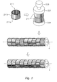
- a fan manufactured by so-called ultrasonic welding is well known in which, as shown in Figure 1 , a resin molded body 211 integrally formed by a circular disk 211a and numerous blades 211b by a mold is provided (resin molding step), subsequently these resin molded bodies 211 are superposed in a direction of a rotation axis of the fan, and then an assembly of these resin molded bodies 211 is subjected to ultrasonic vibration while being pressurized in the direction of the rotation axis: thereby these resin molded bodies 211 are molded to each other (ultrasonic welding step).
- members disposed at both ends of the assembly of the resin molded bodies 211 shown in Figure 1 are resonant bodies called cones 221 and 222 for transmitting vibration energy by ultrasound to the resin molded bodies 211
- a member disposed adjacently to the cone 221 is a vibrator called cylinder 223 for converting an electronic signal from an oscillator (not shown) into vibration energy by ultrasound.
- resin cross flow fans manufactured by using long blades that extend the entire length of the fan.
- resin cross flow fans there is provided a fan manufactured by pressing in and welding long blades that extend the entire length of the fan to circular disks having a plurality of blade insertion grooves formed therein, through these blade insertion grooves coated with solvent, from the direction of the outer circumference of the circular disks (see patent document 1).
- the length of the blades 211b cannot be lengthened due to restrictions such as a draft angle of the mold and the like. This causes a problem of an increased number of circular disks 211a. This also causes a problem that a structure suitable for improving air blowing performance, such as where the blades 211b are disposed inclined with respect to the rotation axis or the like, cannot be made.
- the ultrasonic welding step can be omitted: therefore, the annealing step for eliminating distortions caused by ultrasonic welding can be omitted and the number of the circular disks 211a shown in Figure 1 can be reduced.
- the blade insertion grooves need to be formed on the circular disks with high dimensional accuracy. When it is not possible to ensure sufficient dimensional accuracy, a gap is created between the blades and the blade insertion grooves. This results in problems such as that the blades are insufficiently pressed in and welded or deformation is caused on the blades and the circular disks, thus impairing fan strength and air blowing performance.
- An object of the present invention is to provide a resin cross flow fan and a manufacturing method thereof in which an annealing step can be omitted and the number of circular disks can be reduced, and which provides improved fan strength and air blowing performance.
- a resin cross flow fan includes a plurality of blades and a plurality of circular disks.
- the plurality of blades are annually disposed about a rotation axis.
- the plurality of circular disks are disposed spaced apart in the direction of the rotation axis, and disposed with insertion portions each constituted by a hole or a groove into which each blade is inserted and projecting portions that project from the periphery of the insertion portions in a direction of the rotation axis.
- Each blade is fixed to the projecting portions by laser welding.
- this resin cross flow fan since the projecting portions are disposed at the periphery of the insertion portions of the circular disks, sections are formed where the projecting portions constituting part of the circular disks overlap with the blades when viewing a circumferential space between the blades from the outer circumference of the circular disks.
- this resin cross flow fan has a structure in which laser irradiation can be performed in a state in which the blades are inserted into the insertion portions.
- this resin cross flow fan is manufactured by inserting the blades into the insertion portions and then welding the blades to the projecting portions by laser welding, it is possible to use long blades and thus the number of circular disks can be reduced.
- the resin cross flow fan of the present invention can provide improved fan strength and air blowing performance since the blades and the circular disks are not easily deformed.
- a resin cross flow fan according to a second aspect of the present invention is the resin cross flow fan according to the first aspect of the present invention, wherein the circular disks further have pressing portions formed thereon for pressing the blades toward the projecting portions in a state in which the blades are inserted into the insertion portions.
- a resin cross flow fan according to a third aspect of the present invention is the resin cross flow fan according to the second aspect of the present invention, wherein the pressing portions are pawl portions that become elastically deformed such that portions that come into contact with the blades can move closer to or away from the projecting portions.
- the pressing portions are the elastically deformable pawl portions, the portions that come into contact with the blades move away from the projecting portions. Thereby, an insertion movement of the blades into the insertion portions is not easily interfered. This enables smooth insertion of the blades into the insertion portions.
- a resin cross flow fan according to a fourth aspect of the present invention is the resin cross flow fan according to any one of the first through third aspects of the present invention, wherein a material constituting the circular disks has a higher light transmittance than a material constituting the blades.
- a resin cross flow fan according to a fifth aspect of the present invention is the resin cross flow fan according to any one of the first through fourth aspects of the present invention, wherein the projecting portions are formed so as to extend along one side of the blades.
- a manufacturing method of a resin cross flow fan includes a providing step, an assembling step, and a welding step.
- the providing step a plurality of blades and a plurality of circular disks are provided, with the plurality of circular disks disposed with insertion portions each constituted by a hole or groove into which each blade is inserted and projecting portions that project from the periphery of the insertion portions in a through thickness direction.
- the assembling step the plurality of blades are assembled onto the plurality of circular disks by inserting the blades into the insertion portions.
- the blades are fixed to the projecting portions by laser welding.
- the projecting portions are disposed at the periphery of the insertion portions of the circular disks. Therefore, in the assembling step, sections are formed where the projecting portions constituting part of the circular disks overlap with the blades when viewing a circumferential space between the blades from the outer circumference of the circular disks.
- laser irradiation can be performed in a state in which the blades are inserted into the insertion portions.
- the long blades can be used in a resin cross flow fan manufactured by this manufacturing method, the number of circular disks can be reduced. In addition, distortion during welding is reduced and thus the annealing step can be omitted.
- the resin cross flow fan of the present invention can provide improved fan strength and air blowing performance since the blades and circular disks are not easily deformed.
- a manufacturing method of a resin cross flow fan according to a seventh aspect of the present invention is the manufacturing method of a resin cross flow fan according to the sixth aspect of the present invention, wherein the circular disks further have pressing portions formed thereon for pressing the blades toward the projecting portions in a state in which the blades are inserted into the insertion portions. In the assembling step, the blades are inserted into the insertion portions and thereby the blades are pressed toward the projecting portions.
- a manufacturing method of a resin cross flow fan according to an eighth aspect of the present invention is the manufacturing method of a resin cross flow fan according to the sixth or seventh aspect of the present invention, wherein the projecting portions are formed so as to extend along one side of the blades. In the welding step, one side of the blades is subjected to laser welding.
- FIG. 2 shows an external perspective view of a resin cross flow fan 1 according to a first embodiment of the present invention.
- line O-O is a rotation axis line of the resin cross flow fan 1 (hereinafter line O-O is referred to as "rotation axis").
- the resin cross flow fan 1 mainly includes a plurality of blades 2, a first end plate 3, a second end plate 4, and support plates 5.
- the plurality of blades 2 are long resin members annually disposed about the rotation axis and extending the entire length of the resin cross flow fan 1.
- Each blade 2 has a cross section having a generally circular arc shape.
- each blade 2 is disposed inclined at predetermined angle instead of in parallel to the rotation axis, in order to improve air blowing performance including noise reduction and the like.
- an ABS resin and the like may be used as the material constituting the blades 2.
- the first end plate 3 is a member constituting an end of the resin cross flow fan 1 in a longitudinal direction, and mainly includes a resin plate portion 31 having a circular disk shape and an axial portion 32 disposed at the center of the plate portion 31.
- the plate portion 31 has a plurality of insertion portions 33 formed therein into which the plurality of blades 2 are inserted respectively, for supporting an end of the plurality of blades 2 in a longitudinal direction.
- the insertion portions 33 are through holes having a shape that corresponds to each blade 2.
- the insertion portions 33 have a hole size slightly larger than the cross sectional size of the blades 2.
- each projecting portion 34 has projecting portions 34 formed thereon which project from the periphery of each insertion portion 33 in the direction of the rotational axis (specifically, toward the support plates 5).
- Each projecting portion 34 is formed so as to surround a convex portion of the periphery of the circular arc shaped blade 2 and both end portions of the same in a circumferential direction.
- each projecting portion 34 includes a welding surface 34a that extends along the convex portion (hereinafter referred to as "welding surface 2a") of the periphery of the blade 2, i.e. a surface facing the projecting portion 34.
- the projecting portions 34 as part of the first end plate 3 and the blades 2 are in a state where the projecting portions 34 as part of the first end plate 3 overlap with the blades 2 when viewing a circumferential space between the blades 2 from the outer circumference of the first end plate 3 (see arrows F in Figures 3 and 4 ). Further, the plurality of blades 2 (specifically, the welding surfaces 2a) are fixed to these projecting portions 34 (specifically, the welding surfaces 34a) by laser welding.
- the portions where the projecting portions 34 overlap with the blades 2 when viewing the circumferential space between the blades 2 are irradiated with a laser in the direction from the outer circumference of the first end plate 3 to the projecting portions 34, and thereby the welding surfaces 34a of the projecting portions 34 are welded to the welding surfaces 2a of the blades 2 (see arrows F in Figures 3 and 4 ).
- laser welding is applied as a welding method, as the material constituting the first end plate 3, it is preferable to use a material having a higher light transmittance than the material constituting the blades 2.
- Figure 3 is a cross sectional view taken along line C-C in Figure 2 and is an enlarged view of only a portion of the first end plate 3.
- Figure 4 is a cross sectional view taken along line E-E in Figure 3 .
- the second end plate 4 is a member that constitutes the other end of the resin cross flow fan 1 in the longitudinal direction (an end portion on the side opposite from the first end plate 3), and mainly includes a resin plate portion 41 having a circular disk shape.
- a circular opening 42 is formed in the plate portion 41 inside of the inner circumference of the plurality of blades 2.
- a boss 6 having an axial portion 61 is fixed to the plate portion 41 so as to cover the opening 42.
- a plurality of insertion portions 43 into which the plurality of blades 2 are inserted respectively are formed in the plate portion 41, for supporting other end of the plurality of blades 2 in the longitudinal direction.
- the insertion portions 43 are through holes having a shape that corresponds to each blade 2.
- the insertion portions 43 have a hole size slightly larger than the cross sectional size of the blades 2.
- the plate portion 41 has projecting portions 44 formed thereon which project from the periphery of each insertion portion 43 in the direction of the rotational axis (specifically, toward the axial portion 61).
- each projecting portion 44 is formed so as to surround the convex portion of the periphery of the circular arc shaped blade 2 and both end portions of the same in the circumferential direction.
- each projecting portion 44 includes a welding surface 44a that extends along the welding surface 2a of the blade 2.
- the projecting portions 44 as described above is formed, the projecting portions 44 as part of the second end plate 4 and the blades 2 are in a state where the projecting portions 44 as part of the second end plate 4 overlap with the blades 2 when viewing the circumferential space between the blades 2 from the outer circumference of the second end plate 4 (see arrows F in Figures 5 and 6 ). Further, the plurality of blades 2 (specifically, the welding surfaces 2a) are fixed to these projecting portions 44 (specifically, the welding surfaces 44a) by laser welding.
- the portions where the projecting portions 44 overlap with the blades 2 when viewing the circumferential space between the blades 2 are irradiated with a laser in the direction from the outer circumference of the second end plate 4 to the projecting portion 44, and thereby the welding surfaces 44a of the projecting portions 44 are welded to the welding surfaces 2a of the blades 2 (see arrows F in Figures 5 and 6 ).
- laser welding is applied as a welding method, as the material constituting the second end plate 4, it is preferable to use a material having a higher light transmittance than the material constituting the blades 2, as is the case with the first end plate 3.
- Figure 5 is a view along arrow D in Figure 2 and is an enlarged view of only a portion of the second end plate 4.
- Figure 6 is a cross sectional view taken along line E-E in Figure 5 .
- the support plate 5 is a member that constitutes a middle portion of the resin cross flow fan 1 in the longitudinal direction.
- four support plates 5 are disposed spaced apart between the first end plate 3 and the second end plate 4.
- Each support plate 5 mainly includes a resin plate portion 51 having a circular disk shape.
- a circular opening 52 is formed in the plate portion 51 inside of the inner circumference of the plurality of blades 2.
- a plurality of insertion portions 53 into which the plurality of blades 2 are inserted respectively are formed in the plate portion 51, for supporting other end of the plurality of blades 2 in the longitudinal direction.
- the insertion portions 53 are through holes having a shape that corresponds to each blade 2.
- the insertion portions 53 have a hole size slightly larger than the cross sectional size of the blades 2.
- the plate portion 51 has projecting portions 54 formed thereon which project from the periphery of each insertion portion 53 in the direction of the rotational axis (specifically, toward the second end plate 4).
- each projecting portion 54 is formed so as to surround the convex portion of the periphery of the circular arc shaped blades 2 and both end portions of the same in the circumferential direction.
- each projecting portion 54 includes a welding surface 54a that extends along the welding surface 2a of the blade 2.
- the projecting portions 54 as part of the support plates 5 and the blades 2 are in a state where the projecting portions 54 as part of the support plates 5 overlap with the blades 2 when viewing the circumferential space between the blades 2 from an outer circumference of the support plates 5 (see arrows F in Figures 7 and 8 ). Further, the plurality of blades 2 (specifically, the welding surfaces 2a) are fixed to these projecting portions 54 (specifically, the welding surfaces 54a) by laser welding.
- the portions where the projecting portions 54 overlap with the blades 2 when viewing the circumferential space between the blades 2 are irradiated with a laser in the direction from the outer circumference of each support plate 5 to the projecting portions 54, and thereby the welding surfaces 54a of the projecting portions 54 are welded to the welding surfaces 2a of the blades 2 (see arrows F in Figures 7 and 8 ).
- laser welding is applied as a welding method, as the material constituting the support plates 5, it is preferable to use a material having a higher light transmittance than the material constituting the blades 2, as is the case with the first end plate 3.
- Figure 7 is a cross sectional view taken along line C-C in Figure 2 and is an enlarged view of only a portion of the support plates 5.
- Figure 8 is a cross sectional view taken along line E-E in Figure 7 .
- the resin cross flow fan 1 is a fan that uses the plurality of long blades 2 that extend the entire length of the resin cross flow fan 1.
- the resin cross flow fan 1 has a structure in which the plates 3, 4, and 5 serving as the plurality of circular disks are disposed spaced apart in the direction of the rotational axis; the blades 2 are inserted into the insertion portions 33, 43, and 53 each constituted by a hole formed in these plates 3, 4, and 5; and further, a laser is irradiated in the direction from the outer circumference of the plates 3, 4, and 5 to the projecting portions 34, 44, and 54 formed on the plates 3, 4, and 5 so as to project from the periphery of the insertion portions 33, 43, and 53 in the direction of the rotational axis: thereby the blades 2 are welded and fixed to the projecting portions 34, 44, and 54.
- Figure 9 is a view of a manufacturing step of the resin cross flow fan 1.
- Figures 10 and 11 are views of a pressing jig 7 used in a welding step.
- the manufacturing method of the resin cross flow fan 1 mainly includes a providing step, an assembling step, and the welding step.
- the providing step is a step in which the plurality of blades 2 and the plates 3, 4, and 5 serving as the plurality of circular disks are provided.
- the plurality of blades 2 are obtained by a material continuously extruded from an extruder and cutting this extruded material into predetermined length.
- the plates 3, 4, and 5 are obtained by injection molding using a mold.
- the assembling step is a step in which the plurality of blades 2 are inserted into the insertion portions 33, 43, and 53 of the plates 3, 4, and 5 and thereby the plurality of blades 2 are assembled onto the plates 3, 4, and 5 serving as the plurality of circular disks in order to obtain an assembly 1a before being subjected to laser welding.
- the assembly 1a is obtained by inserting the plurality of blades 2 into the second end plate 4, the plurality of the support plates 5, and the first end plate 3 in that order and disposing each of the plates 3, 4, and 5 with a predetermined space therebetween in the direction of the rotational axis.
- the assembly 1a as described above is obtained, a section is formed where the projecting portions 34, 44, and 54 as part of the plates 3, 4, and 5 overlap with the blades 2 when viewing the circumferential space between the blades 2 from the outer circumference of the plates 3, 4, and 5.
- the insertion portions 33 have a hole size slightly larger than the cross sectional size of the blades 2, it is possible to smoothly assemble the blades 2 onto the plates 3, 4, and 5 and to prevent the blades 2 and the plates 3, 4, and 5 from being deformed.
- the welding step is a step in which the blades 2 are fixed to the projecting portions 34, 44, and 54 of the plates 3, 4, and 5 by laser welding. Specifically, a laser is irradiated in the direction from the outer circumference of the plates 3, 4, and 5 to the projecting portions 34, 44, and 54 of the assembly 1a, and thereby the welding surfaces 2a of the blades 2 are welded to the welding surfaces 34a, 44a, and 54a of the projecting portions 34, 44, and 54.
- a state in which the welding surfaces 2a of the blades 2 are closely contacted with the welding surfaces 34a, 44a, and 54a of the projecting portions 34, 44, and 54 is achieved before laser irradiation is performed.
- a state in which the welding surfaces 2a of blades 2 are closely contacted with the welding surfaces 34a, 44a, and 54a of the projecting portions 34, 44, and 54 is achieved by using a pressing jig configured to press the blades 2 inserted into the insertion portions 33, 43, and 53 toward the projecting portions 34, 44, and 54.
- a jig that can be used as this type of pressing jig is capable of being inserted into the assembly 1a from the opening 42 of the second end plate 4 and has a structure disposed with a member that extends to the positions of the blades 2 and the projecting portions 34, 44, and 54 in a radial direction so as to press the blades 2 toward the projecting portions 34, 44, and 54, with the jig being inserted into the assembly 1a.
- a pressing jig 7 shown in Figures 9 to 11 is used.
- the pressing jig 7 mainly includes a cylindrical cylinder 71 and pressing pawls 72 that extend to the positions of the blades 2 and the projecting portions 34, 44, and 54 in the radial direction.
- the cylinder 71 has an axial length substantially same as that of the assembly 1a.
- the cylinder 71 is a hollow cylindrical member having an outside diameter smaller than the radii of the openings 42 and 52 of the plates 4 and 5, and a plurality of holes 71a are formed on its circumferential surface.
- the holes 71a are formed so as to correspond to the positions of each of the plates 3, 4, and 5 of the assembly 1a in the axial direction, and in addition, each hole 71a is formed so as to correspond to a circumferential space between the blades 2.
- the pressing pawls 72 are disposed so as to correspond to the holes 71a and configured to extend from the holes 71a toward the outer circumference of the cylinder 71 as a result of rotation of an axial portion 73 disposed at one end of the cylinder 71 in the axial direction in a direction of arrow R.
- a laser is irradiated in the direction from the outer circumference of the plates 3, 4, and 5 to the projecting portions 34, 44, and 54 of the assembly 1a after the welding surfaces 2a of the blades 2 are closely contacted with the welding surfaces 34a, 44a, and 54a of the projecting portions 34, 44, and 54 by inserting the pressing jig 7 into the assembly 1a from the opening 42 of the second end plate 4; rotating the axial portion 73 in the direction of arrow R so as to extend the pressing pawls 72 to the positions of the blades 2 and the projecting portions 34, 44, and 54 in the radial direction; and pressing the concave portion of the blades 2 (i.e., a surface on the side opposite from the welding surface 2a) toward the projecting portions 34, 44, and 54 by the pressing pawl 72.
- the material constituting the plates 3, 4, and 5 a material having a higher light transmittance than the material constituting the blades 2 is used. Therefore, laser welding of the blades 2 to the projecting portions 34, 44, and 54 can be easily performed from the direction of the projecting portions 34, 44, and 54.
- just one side i.e., the welding surfaces 2a constituting the convex portions of the blades 2 is welded to the projecting portions 34, 44, and 54 on the circular disks. Therefore, it is possible to reduce the number of portions to be laser welded.
- a laser can be sequentially irradiated to the projecting portions 34, 44, and 54 juxtaposed in the circumferential direction of the plates 3, 4, and 5. Therefore, it is possible to improve the operation efficiency in laser welding.
- the resin cross flow fan 1 and the manufacturing method thereof in this embodiment have the following characteristics.
- this resin cross flow fan 1 has a structure in which a laser can be irradiated to the projecting portions 34, 44, and 54 in a state in which the blades 2 are inserted into the insertion portions 33, 43, and 53.
- this resin cross flow fan 1 is manufactured by inserting the blades 2 into the insertion portions 33, 43, and 53 in the assembling step and then welding the blades 2 to the projecting portions 34, 44, and 54 by laser welding in the welding step, it is possible to use the long blades, which therefore enables reduction in the number of support plates 5 (which enables reduction in weight). In addition, distortion during welding is reduced and thus the annealing step can be omitted. Further, unlike the fan manufactured by pressing in and welding the blades 2 into the insertion portions 33, 43, and 53 of the plates 3, 4, and 5, the resin cross flow fan 1 can provide improved fan strength and air blowing performance since the blades 2 and the plates 3, 4, and 5 are not easily deformed.
- the projecting portions 34, 44, and 54 are formed so as to extend along one side of the blades 2, it is possible to reduce the number of portions to be laser welded.
- the insertion portions 33, 43, and 53 of the plates 3, 4, and 5 may have a hole size slightly larger than the cross sectional size of the blades 2. This enables, in the assembling step, to smoothly assemble the blades 2 onto the plates 3, 4, and 5 and to prevent the blades 2 and the plates 3, 4, and 5 from being deformed.
- a laser can be sequentially irradiated to the projecting portions 34, 44, and 54 juxtaposed in the circumferential direction of the plates 3, 4, and 5. Therefore, it is possible to improve the operation efficiency in laser welding.
- the projecting portions 34, 44, and 54 project from the plates 3, 4, and 5 in one direction of the rotational axis (i.e., toward one side).
- the projecting portions 34, 44, and 54 may project from the plates 3, 4, and 5 in both directions of the rotational axis (i.e., toward both sides).
- the support plates 5 are described by way of example (descriptions of the plates 3 and 4 are omitted).
- the projecting portions 54 are formed on each support plate 5 so as to form not only the second end plate 4 but also the first end plate 3, and the blades 2 are laser welded at both sides of each support plate 5. This increases the number of portions to be welded. However, the blades 2 are more securely fixed to the projecting portions 34, 44, and 54.
- the insertion portions 33, 43, and 53 are the through holes.
- the insertion portions 33, 43, and 53 may be cutout grooves that extend to the outer circumferential edge of the plate portions 31, 41, and 51.
- the support plates 5 are described by way of example (descriptions of the plates 3 and 4 are omitted).
- the insertion portions 53 are formed to be cutout grooves that extend to the outer circumferential edge of the plate portion 51. This enables insertion of the blades 2 into the insertion portions 33, 43, and 53 from the outer circumferential edge of the plates 3, 4, and 5.
- FIG 14 shows an external perspective view of a resin cross flow fan 101 according to a second embodiment of the present invention.
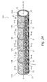
- the resin cross flow fan 101 according to the second embodiment of the present invention is a fan that uses the plurality of long blades 2 that extend the entire length of the resin cross flow fan 101 and mainly includes the plurality of blades 2, a first end plate 103, a second end plate 104, and support plates 105.
- the resin cross flow fan 101 has a structure similar to that of the resin cross flow fan 1 except for that the plates 103, 104, and 105 are different from the plates 3, 4, and 5 of the resin cross flow fan 1 in the first embodiment. Therefore, descriptions are given below with respect to the structures of the plates 103, 104, and 105.
- the first end plate 103 is a member that supports an end of the plurality of blades 2 in the longitudinal direction, and includes the resin plate portion 31 having a circular disk shape, the axial portion 32 disposed at the center of the plate portion 31, the plurality of insertion portions 33 into which the plurality of blades 2 are inserted respectively, and the projecting portions 34 that project from the periphery of each insertion portion 33 in the direction of the rotational axis (specifically, toward the support plates 5).
- the first end plate 103 has pressing portions 35 formed thereon for pressing the blades 2 toward the projecting portions 34 in a state in which the blades 2 are inserted into the insertion portions 33.
- the pressing portions 35 are pawl portions that become elastically deformed such that portions 35a that come into contact with the blades 2 can move closer to or away from the projecting portions 34. More specifically, each pressing portion 35 is formed at a position facing the concave side of the blade 2 within the periphery of the insertion portion 33 so as to press the concave portion of the periphery of the blade 2 toward the projecting portion 34.
- the pressing portions 35 are inclined to the concave side of the blades 2 and also project from the periphery of the insertion portions 33 in the direction of the rotational axis (specifically, toward the support plates 5). Further, the plurality of blades 2 (specifically, the welding surfaces 2a) are fixed to these projecting portions 34 (specifically, the welding surfaces 34a) by laser welding.
- the portions where the projecting portions 34 overlap with the blades 2 when viewing the circumferential space between the blades 2 are irradiated with a laser in the direction from the outer circumference of the first end plate 103 to the projecting portions 34, and thereby the welding surfaces 34a of the projecting portions 34 are welded to the welding surfaces 2a of the blades 2 (see arrows F in Figures 15 and 16 ).
- the pressing portions 35 press the blades 2 (specifically, the welding surfaces 2a) toward the projecting portions 34 (specifically, the welding surfaces 34a) in order to achieve a close contact between the blades 2 and the projecting portions 34.
- Figure 15 is a cross sectional view taken along line C-C in Figure 14 and is an enlarged view of only a portion of the first end plate 103.
- Figure 16 is a cross sectional view taken along line E-E in Figure 15 .
- the second end plate 104 is a member that supports the other end (end portion on the side opposite from the first end plate 103) of the plurality of blades 2 in the longitudinal direction, and includes the resin plate portion 41 having a circular disk shape, the axial portion 42 disposed at the center of the plate portion 41, the plurality of insertion portions 43 into which the plurality of blades 2 are inserted respectively, and the projecting portions 44 that project from the periphery of each insertion portion 43 in the direction of the rotational axis (specifically, toward the axial portion 61).
- the second end plate 104 has pressing portions 45 formed thereon for pressing the blades 2 toward the projecting portions 44 in a state in which the blades 2 are inserted into the insertion portions 43.
- the pressing portions 45 are pawl portions that become elastically deformed such that portions 45a that come into contact with the blades 2 can move closer to or away from the projecting portions 44. More specifically, each pressing portion 45 is formed at a position facing the concave side of the blade 2 within the periphery of the insertion portion 43 so as to press the concave portion of the periphery of the blade 2 toward the projecting portion 44.
- the pressing portions 45 are inclined to the concave side of the blades 2 and also project from the periphery of the insertion portions 43 in the direction of the rotational axis (specifically, toward the axial portion 42). Further, the plurality of blades 2 (specifically, the welding surfaces 2a) are fixed to these projecting portions 44 (specifically, the welding surfaces 44a) by laser welding.
- the portions where the projecting portions 44 overlap with the blades 2 when viewing the circumferential space between the blades 2 are irradiated with a laser in the direction from the outer circumference of the second end plate 104 to the projecting portions 44, and thereby the welding surfaces 44a of the projecting portions 44 are welded to the welding surfaces 2a of the blades 2 (see arrows F in Figures 17 and 18 ).
- the pressing portions 45 press the blades 2 (specifically, the welding surfaces 2a) toward the projecting portions 44 (specifically, the welding surfaces 44a) in order to achieve a close contact between the blades 2 and the projecting portions 44.
- Figure 17 is a view along arrow D in Figure 14 and is an enlarged view of only a portion of the second end plate 104.
- Figure 18 is a cross sectional view taken along line E-E in Figure 17 .
- each support plate 105 includes the resin plate portion 51 having a circular disk shape, the circular shaped opening 52 formed in the plate portion 51 at a position inside of the inner circumference of the plurality of blades 2, the plurality of insertion portions 53 into which the plurality of blades 2 are inserted respectively, and the projecting portions 54 that project from the periphery of each insertion portion 53 in the direction of the rotational axis (specifically, toward the second end plate 104).
- the support plates 105 have pressing portions 55 formed thereon for pressing the blades 2 toward the projecting portions 54 in a state in which the blades 2 are inserted into the insertion portions 53.
- the pressing portions 55 are pawl portions that become elastically deformed such that portions 55a that come into contact with the blades 2 can move closer to or away from the projecting portions 54. More specifically, each pressing portion 55 is formed at a position facing the concave side of the blade 2 within the periphery of the insertion portions 53 so as to press the concave portion of the periphery of the blade 2 toward the projecting portion 54.
- the pressing portions 55 are inclined to the concave side of the blades 2 and also project from the periphery of the insertion portions 53 in the direction of the rotational axis (specifically, toward the second end plate 104). Further, the plurality of blades 2 (specifically, the welding surfaces 2a) are fixed to these projecting portions 54 (specifically, the welding surfaces 54a) by laser welding.
- the portions where the projecting portions 54 overlap with the blades 2 when viewing the circumferential space between the blades 2 are irradiated with a laser in the direction from the outer circumference of the support plates 105 to the projecting portions 54, and thereby the welding surfaces 54a of the projecting portions 54 are welded to the welding surfaces 2a of the blades 2 (see arrows F in Figures 19 and 20 ).
- the pressing portions 55 press the blades 2 (specifically, the welding surfaces 2a) toward the projecting portions 54 (specifically, the welding surfaces 54a) in order to achieve a close contact between the blades 2 and the projecting portions 54.
- Figure 19 is a cross sectional view taken along line C-C in Figure 14 and is an enlarged view of only a portion of the support plates 105.
- Figure 20 is a cross sectional view taken along line E-E in Figure 19 .
- Figure 21 is a view of a manufacturing step of the resin cross flow fan 101.
- the manufacturing method of the resin cross flow fan 101 mainly includes a providing step, an assembling step, and a welding step.
- the providing step is a step in which the plurality of blades 2 and the plates 103, 104, and 105 serving as the plurality of circular disks are provided.
- the plurality of blades 2 are obtained by a material continuously extruded from an extruder and cutting this extruded material into predetermined length.
- the plates 103, 104, and 105 are obtained by injection molding using a mold.
- the assembling step is a step in which the plurality of blades 2 are inserted into the insertion portions 33, 43, and 53 of the plates 103, 104, and 105 and thereby the plurality of blades 2 are assembled onto the plates 103, 104, and 105 serving as the plurality of circular disks in order to obtain an assembly 101a before being subjected to laser welding.
- the assembly 101a is obtained by inserting the plurality of blades 2 into the second end plate 104, the plurality of the support plates 105, and the first end plate 103 in that order and disposing each of the plates 103, 104, and 105 with a predetermined space therebetween in the direction of the rotational axis.
- the plates 103, 104, and 105 have the pressing portions 35, 45, and 55 formed thereon for pressing the blades 2 toward the projecting portions 34, 44, and 54 in a state in which the blades 2 are inserted into the insertion portions 33, 43, and 53.
- the blades 2 can be closely contacted with the projecting portions 34, 44, and 54 simply by inserting the blades 2 into the insertion portions 33, 43, and 53.
- the insertion portions 33 have a hole size slightly larger than the cross sectional size of the blades 2, it is possible to smoothly assemble the blades 2 onto the plates 103, 104, and 105 and to prevent the blades 2 and the plates 103, 104, and 105 from being deformed.
- the pressing portions 35, 45, and 55 are the pawl portions that become elastically deformed such that the portions 35a, 45a, and 55a that come into contact with the blades 2 can move closer to or away from the projecting portions 34, 44, and 54. Thereby, an insertion movement of the blades 2 into the insertion portions 33, 43, and 53 is not easily interfered.
- the welding step is a step in which the blades 2 are fixed to the projecting portions 34, 44, and 54 of the plates 103, 104, and 105 by laser welding. Specifically, a laser is irradiated in the direction from the outer circumference of the plates 103, 104, and 105 to the projecting portions 34, 44, and 54 of the assembly 101a, and thereby the welding surfaces 2a of the blades 2 are welded to the welding surfaces 34a, 44a, and 54a of the projecting portions 34, 44, and 54.
- the resin cross flow fan 101 and the manufacturing method thereof in this embodiment have the following characteristics in addition to the characteristics of the resin cross flow fan 1 and the manufacturing method thereof in the first embodiment.
- the blades 2 can be closely contacted with the projecting portions 34, 44, and 54 simply by inserting the blades 2 into the insertion portions 33, 43, and 53. This eliminates the need for a jig (for example, the pressing jig 7 in the first embodiment) for pressing the blades 2 toward the projecting portions 34, 44, and 54 when performing laser welding in the welding step, and each blade 2 can be reliably welded.
- a jig for example, the pressing jig 7 in the first embodiment
- the pressing portions 35, 45, and 55 are the pawl portions that become elastically deformed such that the portions 35a, 45a, and 55a that come into contact with the blades 2 can move closer to or away from the projecting portions 34, 44, and 54. Therefore, the portions that come into contact with the blades 2 move away from the projecting portions 34, 44, and 54, and thereby an insertion movement of the blades 2 into the insertion portions 33, 43, and 53 is not easily interfered. This enables smooth insertion of the blades 2 into the insertion portions 33, 43, and 53.
- the portions 35a, 45a, and 55a of the pressing portions 35, 45, and 55 which come into contact with the concave side of the blades 2, have a slightly pointed shape, and the contact therebetween is substantially a line contact. However, they may be configured to extend along the concave side of the blades 2 such that the contact therebetween is a planer contact. More specifically, the support plates 105 are described by way of example (descriptions of the plates 103 and 104 are omitted). As shown in Figure 22 , the portions 55a of the pressing portions 55 are configured in a flat shape that extends along the concave side of the blades 2. This enables a further improvement of the close contact condition between the blades 2 and the projecting portions 34, 44, and 54 by the pressing portions 35, 45, and 55.
- the pressing portions 35, 45, and 55 are formed on the plates 103, 104, and 105 in one direction of the rotational axis (i.e., on one side), the pressing portions 35, 45, and 55 may be formed on the plates 103, 104, and 105 in both directions of the rotational axis (i.e., on both sides). More specifically, the support plates 105 are described by way of example (descriptions of the plates 103 and 104 are omitted).
- the pressing portions 55 are formed on each support plate 105 so as to form not only the second end plate 104 but also the first end plate 103, in order to press the blades 2 toward the projecting portions 34 from both sides of each support plate 105. This enables a further improvement of the close contact condition between the blades 2 and the projecting portions 34, 44, and 54 by the pressing portions 35, 45, and 55.
- the pressing portions 35, 45, and 55 are formed on the plates 103, 104, and 105 in both directions of the rotational axis (i.e., on both sides), and the projecting portions 34, 44, and 54 project from the plates 103, 104, and 105 in one direction of the rotational axis (i.e., toward one side).
- the projecting portions 34, 44, and 54 may project from the plates 103, 104, and 105 in both directions of the rotational axis (i.e., toward both sides). This enables a further improvement of the close contact condition between the blades 2 and the projecting portions 34, 44, and 54 by the pressing portions 35, 45, and 55.
- the blades 2 are more securely fixed to the projecting portions 34, 44, and 54.
- the insertion portions 33, 43, and 53 are the through holes.
- the insertion portions 33, 43, and 53 may be cutout grooves that extend to the outer circumferential edge of the plate portions 31, 41, and 51.
- the support plates 105 are described by way of example (descriptions of the plates 103 and 104 are omitted).
- the insertion portions 53 are formed to be cutout grooves that extend to the outer circumferential edge of the plate portion 51. This enables insertion of the blades 2 into the insertion portions 33, 43, and 53 from the outer circumferential edge of the plates 103, 104, and 105.
- the projecting portions 34, 44, and 54 are formed so as to extend substantially the entire convex portion of the blades 2, however, they may extend along only a portion of the same.
- Application of the present invention can provide a resin cross flow fan and a manufacturing method thereof in which an annealing step can be omitted and the number of circular disks can be reduced, and which provides improved fan strength and air blowing performance.
Landscapes
- Engineering & Computer Science (AREA)
- Mechanical Engineering (AREA)
- General Engineering & Computer Science (AREA)
- Structures Of Non-Positive Displacement Pumps (AREA)
Abstract
Description
- The present invention relates to a resin cross flow fan and a manufacturing method thereof.
- As a conventional resin cross flow fan, a fan manufactured by so-called ultrasonic welding is well known in which, as shown in
Figure 1 , a resin moldedbody 211 integrally formed by acircular disk 211a andnumerous blades 211b by a mold is provided (resin molding step), subsequently these resin moldedbodies 211 are superposed in a direction of a rotation axis of the fan, and then an assembly of these resin moldedbodies 211 is subjected to ultrasonic vibration while being pressurized in the direction of the rotation axis: thereby these resin moldedbodies 211 are molded to each other (ultrasonic welding step). Here, members disposed at both ends of the assembly of the resin moldedbodies 211 shown inFigure 1 (inFigure 1 , nine resin moldedbodies 211 are superposed) in the direction of the rotation axis are resonant bodies calledcones bodies 211, and a member disposed adjacently to thecone 221 is a vibrator calledcylinder 223 for converting an electronic signal from an oscillator (not shown) into vibration energy by ultrasound. - In addition, unlike the above described resin cross flow fan, there have been invented resin cross flow fans manufactured by using long blades that extend the entire length of the fan. As an example of these resin cross flow fans, there is provided a fan manufactured by pressing in and welding long blades that extend the entire length of the fan to circular disks having a plurality of blade insertion grooves formed therein, through these blade insertion grooves coated with solvent, from the direction of the outer circumference of the circular disks (see patent document 1).
-
Japanese Patent Application Publication No. H10-196584 - With the above described fan manufactured by the method in which the resin molded
bodies 211 integrally formed by thecircular disk 211a and theblades 211b are superimposed and then welded to each other by ultrasound, as shown inFigure 1 , distortion is caused on the assembly after being subjected to the ultrasonic welding step (see two-dot chain lines A inFigure 1 ). Therefore, the whole assembly needs to be annealed after being subjected to ultrasonic welding in order to eliminate such distortion (annealing step; see two-dot chain lines B inFigure 1 ). The annealing step is performed for a very long duration. This causes a problem of higher manufacturing cost. In addition, since the resin moldedbodies 211 are injection molded by a mold, the length of theblades 211b cannot be lengthened due to restrictions such as a draft angle of the mold and the like. This causes a problem of an increased number ofcircular disks 211a. This also causes a problem that a structure suitable for improving air blowing performance, such as where theblades 211b are disposed inclined with respect to the rotation axis or the like, cannot be made. - With the above described fan manufactured by pressing in and welding the long blades to the circular disks having the plurality of blade insertion grooves formed therein through these blade insertion grooves coated with solvent from the direction of the outer circumference of the circular disks, the ultrasonic welding step can be omitted: therefore, the annealing step for eliminating distortions caused by ultrasonic welding can be omitted and the number of the
circular disks 211a shown inFigure 1 can be reduced. However, since the blades are fixed to the circular disks by pressing them into the blade insertion grooves and welding by solvent, the blade insertion grooves need to be formed on the circular disks with high dimensional accuracy. When it is not possible to ensure sufficient dimensional accuracy, a gap is created between the blades and the blade insertion grooves. This results in problems such as that the blades are insufficiently pressed in and welded or deformation is caused on the blades and the circular disks, thus impairing fan strength and air blowing performance. - An object of the present invention is to provide a resin cross flow fan and a manufacturing method thereof in which an annealing step can be omitted and the number of circular disks can be reduced, and which provides improved fan strength and air blowing performance.
- A resin cross flow fan according to a first aspect of the present invention includes a plurality of blades and a plurality of circular disks. The plurality of blades are annually disposed about a rotation axis. The plurality of circular disks are disposed spaced apart in the direction of the rotation axis, and disposed with insertion portions each constituted by a hole or a groove into which each blade is inserted and projecting portions that project from the periphery of the insertion portions in a direction of the rotation axis. Each blade is fixed to the projecting portions by laser welding.
- With this resin cross flow fan, since the projecting portions are disposed at the periphery of the insertion portions of the circular disks, sections are formed where the projecting portions constituting part of the circular disks overlap with the blades when viewing a circumferential space between the blades from the outer circumference of the circular disks. In other words, this resin cross flow fan has a structure in which laser irradiation can be performed in a state in which the blades are inserted into the insertion portions. Further, since this resin cross flow fan is manufactured by inserting the blades into the insertion portions and then welding the blades to the projecting portions by laser welding, it is possible to use long blades and thus the number of circular disks can be reduced. In addition, distortion during welding is reduced and thus an annealing step can be omitted. Further, unlike a fan manufactured by pressing in and welding the blades into the insertion portions of the circular disks, the resin cross flow fan of the present invention can provide improved fan strength and air blowing performance since the blades and the circular disks are not easily deformed.
- A resin cross flow fan according to a second aspect of the present invention is the resin cross flow fan according to the first aspect of the present invention, wherein the circular disks further have pressing portions formed thereon for pressing the blades toward the projecting portions in a state in which the blades are inserted into the insertion portions.
- With this resin cross flow fan, since the pressing portions are formed on the circular disks, the blades can be closely contacted with the projecting portions simply by inserting the blades into the insertion portions. This eliminates the need for a jig for pressing the blades to the projecting portions when performing laser welding, and each blade can be reliably welded.
- A resin cross flow fan according to a third aspect of the present invention is the resin cross flow fan according to the second aspect of the present invention, wherein the pressing portions are pawl portions that become elastically deformed such that portions that come into contact with the blades can move closer to or away from the projecting portions.
- With this resin cross flow fan, since the pressing portions are the elastically deformable pawl portions, the portions that come into contact with the blades move away from the projecting portions. Thereby, an insertion movement of the blades into the insertion portions is not easily interfered. This enables smooth insertion of the blades into the insertion portions.
- A resin cross flow fan according to a fourth aspect of the present invention is the resin cross flow fan according to any one of the first through third aspects of the present invention, wherein a material constituting the circular disks has a higher light transmittance than a material constituting the blades.
- With this resin cross flow fan, since the material constituting the circular disks has a higher light transmittance than the material constituting the blades, laser welding of the blades to the projecting portion can be easily performed from the direction of the projecting portions.
- A resin cross flow fan according to a fifth aspect of the present invention is the resin cross flow fan according to any one of the first through fourth aspects of the present invention, wherein the projecting portions are formed so as to extend along one side of the blades.
- With this resin cross flow fan, since the projecting portions are formed so as to extend along one side of the blades, it is possible to reduce the number of portions to be laser welded.
- A manufacturing method of a resin cross flow fan according to a sixth aspect of the present invention includes a providing step, an assembling step, and a welding step. In the providing step, a plurality of blades and a plurality of circular disks are provided, with the plurality of circular disks disposed with insertion portions each constituted by a hole or groove into which each blade is inserted and projecting portions that project from the periphery of the insertion portions in a through thickness direction. In the assembling step, the plurality of blades are assembled onto the plurality of circular disks by inserting the blades into the insertion portions. In the welding step, the blades are fixed to the projecting portions by laser welding.
- With this manufacturing method of a resin cross flow fan, the projecting portions are disposed at the periphery of the insertion portions of the circular disks. Therefore, in the assembling step, sections are formed where the projecting portions constituting part of the circular disks overlap with the blades when viewing a circumferential space between the blades from the outer circumference of the circular disks. In other words, with this manufacturing method, laser irradiation can be performed in a state in which the blades are inserted into the insertion portions. Further, since the long blades can be used in a resin cross flow fan manufactured by this manufacturing method, the number of circular disks can be reduced. In addition, distortion during welding is reduced and thus the annealing step can be omitted. Further, unlike a fan manufactured by pressing in and welding the blades into the insertion portions of the circular disks, the resin cross flow fan of the present invention can provide improved fan strength and air blowing performance since the blades and circular disks are not easily deformed.
- A manufacturing method of a resin cross flow fan according to a seventh aspect of the present invention is the manufacturing method of a resin cross flow fan according to the sixth aspect of the present invention, wherein the circular disks further have pressing portions formed thereon for pressing the blades toward the projecting portions in a state in which the blades are inserted into the insertion portions. In the assembling step, the blades are inserted into the insertion portions and thereby the blades are pressed toward the projecting portions.
- With this manufacturing method of a resin cross flow fan, since the pressing portions are formed on the circular disks, in the assembling step, the blades can be closely contacted with the projecting portions simply by inserting the blades into the insertion portions. This eliminates the need for a jig for pressing the blades toward the projecting portions in the welding step, and each blade can be reliably welded.
- A manufacturing method of a resin cross flow fan according to an eighth aspect of the present invention is the manufacturing method of a resin cross flow fan according to the sixth or seventh aspect of the present invention, wherein the projecting portions are formed so as to extend along one side of the blades. In the welding step, one side of the blades is subjected to laser welding.
- With this manufacturing method of a resin cross flow fan, since the projecting portions are formed so as to extend along one side of the blades and only one side of the blades is welded to the circular disks in the welding step, it is possible to reduce the number of portions to be laser welded.
-
-
Figure 1 is a view of an assembling step of a conventional resin cross flow fan. -
Figure 2 is an external perspective view of a resin cross flow fan according to a first embodiment of the present invention. -
Figure 3 is a cross sectional view taken along line C-C inFigure 2 and is an enlarged view of only a portion of a first end plate of the resin cross flow fan according to the first embodiment. -
Figure 4 is a cross sectional view taken along line E-E inFigure 3 . -
Figure 5 is a view along arrow D inFigure 2 and is an enlarged view of only a portion of a second end plate of the resin cross flow fan according to the first embodiment. -
Figure 6 is a cross sectional view taken along line E-E inFigure 5 . -
Figure 7 is a cross sectional view taken along line C-C inFigure 2 and is an enlarged view of only a portion of a support plate of the resin cross flow fan according to the first embodiment. -
Figure 8 is a cross sectional view taken along line E-E inFigure 7 . -
Figure 9 is a view of a manufacturing step of the resin cross flow fan according to the first embodiment. -
Figure 10 is a view of a pressing jig used in a welding step. -
Figure 11 is a view of the pressing jig used in the welding step. -
Figure 12 is a view for describing a resin cross flow fan according to a modified example 1 of the first embodiment and corresponding toFigure 8 . -
Figure 13 is a view for describing a resin cross flow fan according to a modified example 2 of the first embodiment and corresponding toFigure 7 . -
Figure 14 is an external perspective view of a resin cross flow fan according to a second embodiment of the present invention. -
Figure 15 is a cross sectional view taken along line C-C inFigure 14 and is an enlarged view of only a portion of a first end plate of the resin cross flow fan according to the second embodiment. -
Figure 16 is a cross sectional view taken along line E-E inFigure 15 . -
Figure 17 is a view along arrow D inFigure 14 and is an enlarged view of only a portion of a second end plate of the resin cross flow fan according to the second embodiment. -
Figure 18 is a cross sectional view taken along line E-E inFigure 17 . -
Figure 19 is a cross sectional view taken along line C-C inFigure 14 and is an enlarged view of only a portion of a support plate of the resin cross flow fan according to the second embodiment. -
Figure 20 is a cross sectional view taken along line E-E inFigure 19 . -
Figure 21 is a view of a manufacturing step of the resin cross flow fan according to the second embodiment. -
Figure 22 is a view for describing a resin cross flow fan according to a modified example 1 of the second embodiment and corresponding toFigure 20 . -
Figure 23 is a view for describing a resin cross flow fan according to a modified example 2 of the second embodiment and corresponding toFigure 20 . -
Figure 24 is a view for describing a resin cross flow fan according to a modified example 3 of the second embodiment and corresponding toFigure 20 . -
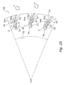
Figure 25 is a view for describing a resin cross flow fan according to a modified example 4 of the second embodiment and corresponding toFigure 19 . -
- 1, 101
- Resin cross flow fan
- 2
- Blade
- 3, 103
- First end plate (circular disk)
- 4, 104
- Second end plate (circular disk)
- 5, 105
- Support plate (circular disk)
- 33, 43, 53
- Insertion portion
- 34, 44, 54
- Projecting portion
- 35, 45, 55
- Pressing portion
- Embodiments of a resin cross flow fan and a manufacturing method thereof according to the present invention are described below with reference to the drawings.
-
Figure 2 shows an external perspective view of a resin cross flow fan 1 according to a first embodiment of the present invention. Note that line O-O is a rotation axis line of the resin cross flow fan 1 (hereinafter line O-O is referred to as "rotation axis"). - The resin cross flow fan 1 mainly includes a plurality of
blades 2, afirst end plate 3, asecond end plate 4, andsupport plates 5. - The plurality of
blades 2 are long resin members annually disposed about the rotation axis and extending the entire length of the resin cross flow fan 1. Eachblade 2 has a cross section having a generally circular arc shape. In addition, eachblade 2 is disposed inclined at predetermined angle instead of in parallel to the rotation axis, in order to improve air blowing performance including noise reduction and the like. In addition, an ABS resin and the like may be used as the material constituting theblades 2. - The
first end plate 3 is a member constituting an end of the resin cross flow fan 1 in a longitudinal direction, and mainly includes aresin plate portion 31 having a circular disk shape and anaxial portion 32 disposed at the center of theplate portion 31. As shown inFigures 3 and4 , theplate portion 31 has a plurality ofinsertion portions 33 formed therein into which the plurality ofblades 2 are inserted respectively, for supporting an end of the plurality ofblades 2 in a longitudinal direction. Theinsertion portions 33 are through holes having a shape that corresponds to eachblade 2. Theinsertion portions 33 have a hole size slightly larger than the cross sectional size of theblades 2. In addition, theplate portion 31 has projectingportions 34 formed thereon which project from the periphery of eachinsertion portion 33 in the direction of the rotational axis (specifically, toward the support plates 5). Each projectingportion 34 is formed so as to surround a convex portion of the periphery of the circular arc shapedblade 2 and both end portions of the same in a circumferential direction. Further, each projectingportion 34 includes awelding surface 34a that extends along the convex portion (hereinafter referred to as "welding surface 2a") of the periphery of theblade 2, i.e. a surface facing the projectingportion 34. Since these projectingportions 34 as described above are formed, the projectingportions 34 as part of thefirst end plate 3 and theblades 2 are in a state where the projectingportions 34 as part of thefirst end plate 3 overlap with theblades 2 when viewing a circumferential space between theblades 2 from the outer circumference of the first end plate 3 (see arrows F inFigures 3 and4 ). Further, the plurality of blades 2 (specifically, the welding surfaces 2a) are fixed to these projecting portions 34 (specifically, the welding surfaces 34a) by laser welding. More specifically, the portions where the projectingportions 34 overlap with theblades 2 when viewing the circumferential space between theblades 2 are irradiated with a laser in the direction from the outer circumference of thefirst end plate 3 to the projectingportions 34, and thereby the welding surfaces 34a of the projectingportions 34 are welded to the welding surfaces 2a of the blades 2 (see arrows F inFigures 3 and4 ). Further, when laser welding is applied as a welding method, as the material constituting thefirst end plate 3, it is preferable to use a material having a higher light transmittance than the material constituting theblades 2. For example, it is conceivable that a color such as transparent, white, or neutral (for example, milky-white) is used for thefirst end plate 3, and a color such as black is used for theblades 2. In addition, an ABS resin and the like may be used as the material constituting thefirst end plate 3. Note thatFigure 3 is a cross sectional view taken along line C-C inFigure 2 and is an enlarged view of only a portion of thefirst end plate 3.Figure 4 is a cross sectional view taken along line E-E inFigure 3 . - The
second end plate 4 is a member that constitutes the other end of the resin cross flow fan 1 in the longitudinal direction (an end portion on the side opposite from the first end plate 3), and mainly includes aresin plate portion 41 having a circular disk shape. Acircular opening 42 is formed in theplate portion 41 inside of the inner circumference of the plurality ofblades 2. Aboss 6 having anaxial portion 61 is fixed to theplate portion 41 so as to cover theopening 42. In addition, as is the case with theplate portion 31 of thefirst end plate 3, as shown inFigures 5 and6 , a plurality ofinsertion portions 43 into which the plurality ofblades 2 are inserted respectively are formed in theplate portion 41, for supporting other end of the plurality ofblades 2 in the longitudinal direction. Theinsertion portions 43 are through holes having a shape that corresponds to eachblade 2. Theinsertion portions 43 have a hole size slightly larger than the cross sectional size of theblades 2. In addition, theplate portion 41 has projectingportions 44 formed thereon which project from the periphery of eachinsertion portion 43 in the direction of the rotational axis (specifically, toward the axial portion 61). As is the case with the projectingportions 34 of thefirst end plate 3, each projectingportion 44 is formed so as to surround the convex portion of the periphery of the circular arc shapedblade 2 and both end portions of the same in the circumferential direction. Further, each projectingportion 44 includes awelding surface 44a that extends along thewelding surface 2a of theblade 2. Since the projectingportions 44 as described above is formed, the projectingportions 44 as part of thesecond end plate 4 and theblades 2 are in a state where the projectingportions 44 as part of thesecond end plate 4 overlap with theblades 2 when viewing the circumferential space between theblades 2 from the outer circumference of the second end plate 4 (see arrows F inFigures 5 and6 ). Further, the plurality of blades 2 (specifically, the welding surfaces 2a) are fixed to these projecting portions 44 (specifically, the welding surfaces 44a) by laser welding. More specifically, the portions where the projectingportions 44 overlap with theblades 2 when viewing the circumferential space between theblades 2 are irradiated with a laser in the direction from the outer circumference of thesecond end plate 4 to the projectingportion 44, and thereby the welding surfaces 44a of the projectingportions 44 are welded to the welding surfaces 2a of the blades 2 (see arrows F inFigures 5 and6 ). Further, when laser welding is applied as a welding method, as the material constituting thesecond end plate 4, it is preferable to use a material having a higher light transmittance than the material constituting theblades 2, as is the case with thefirst end plate 3. For example, it is conceivable that a color such as transparent, white, or neutral (for example, milky-white) is used for thesecond end plate 4, and a color such as black is used for theblades 2. In addition, an ABS resin and the like may be used as the material constituting thesecond end plate 4. Note thatFigure 5 is a view along arrow D inFigure 2 and is an enlarged view of only a portion of thesecond end plate 4.Figure 6 is a cross sectional view taken along line E-E inFigure 5 . - The
support plate 5 is a member that constitutes a middle portion of the resin cross flow fan 1 in the longitudinal direction. Here, foursupport plates 5 are disposed spaced apart between thefirst end plate 3 and thesecond end plate 4. Eachsupport plate 5 mainly includes aresin plate portion 51 having a circular disk shape. Acircular opening 52 is formed in theplate portion 51 inside of the inner circumference of the plurality ofblades 2. In addition, as is the case with theplate portion 31 of thefirst end plate 3, as shown inFigures 7 and8 , a plurality ofinsertion portions 53 into which the plurality ofblades 2 are inserted respectively are formed in theplate portion 51, for supporting other end of the plurality ofblades 2 in the longitudinal direction. Theinsertion portions 53 are through holes having a shape that corresponds to eachblade 2. Theinsertion portions 53 have a hole size slightly larger than the cross sectional size of theblades 2. In addition, theplate portion 51 has projectingportions 54 formed thereon which project from the periphery of eachinsertion portion 53 in the direction of the rotational axis (specifically, toward the second end plate 4). As is the case with the projectingportions 34 of thefirst end plate 3, each projectingportion 54 is formed so as to surround the convex portion of the periphery of the circular arc shapedblades 2 and both end portions of the same in the circumferential direction. Further, each projectingportion 54 includes awelding surface 54a that extends along thewelding surface 2a of theblade 2. Since the projectingportion 54 as described above is formed, the projectingportions 54 as part of thesupport plates 5 and theblades 2 are in a state where the projectingportions 54 as part of thesupport plates 5 overlap with theblades 2 when viewing the circumferential space between theblades 2 from an outer circumference of the support plates 5 (see arrows F inFigures 7 and8 ). Further, the plurality of blades 2 (specifically, the welding surfaces 2a) are fixed to these projecting portions 54 (specifically, the welding surfaces 54a) by laser welding. More specifically, the portions where the projectingportions 54 overlap with theblades 2 when viewing the circumferential space between theblades 2 are irradiated with a laser in the direction from the outer circumference of eachsupport plate 5 to the projectingportions 54, and thereby the welding surfaces 54a of the projectingportions 54 are welded to the welding surfaces 2a of the blades 2 (see arrows F inFigures 7 and8 ). Further, when laser welding is applied as a welding method, as the material constituting thesupport plates 5, it is preferable to use a material having a higher light transmittance than the material constituting theblades 2, as is the case with thefirst end plate 3. For example, it is conceivable that a color such as transparent, white, or neutral (for example, milky-white) is used for thesupport plates 5, and a color such as black is used for theblades 2. In addition, an ABS resin and the like may be used as the material constituting thesupport plates 5. Note thatFigure 7 is a cross sectional view taken along line C-C inFigure 2 and is an enlarged view of only a portion of thesupport plates 5.Figure 8 is a cross sectional view taken along line E-E inFigure 7 . - As described above, the resin cross flow fan 1 is a fan that uses the plurality of
long blades 2 that extend the entire length of the resin cross flow fan 1. The resin cross flow fan 1 has a structure in which theplates blades 2 are inserted into theinsertion portions plates plates portions plates insertion portions blades 2 are welded and fixed to the projectingportions - Next, a manufacturing method of the above described resin cross flow fan 1 is described with reference to
Figures 2 to 11 . Here,Figure 9 is a view of a manufacturing step of the resin cross flow fan 1.Figures 10 and 11 are views of apressing jig 7 used in a welding step. - The manufacturing method of the resin cross flow fan 1 mainly includes a providing step, an assembling step, and the welding step.
- The providing step is a step in which the plurality of
blades 2 and theplates blades 2 are obtained by a material continuously extruded from an extruder and cutting this extruded material into predetermined length. In addition, theplates - The assembling step is a step in which the plurality of
blades 2 are inserted into theinsertion portions plates blades 2 are assembled onto theplates assembly 1a before being subjected to laser welding. Specifically, theassembly 1a is obtained by inserting the plurality ofblades 2 into thesecond end plate 4, the plurality of thesupport plates 5, and thefirst end plate 3 in that order and disposing each of theplates assembly 1a as described above is obtained, a section is formed where the projectingportions plates blades 2 when viewing the circumferential space between theblades 2 from the outer circumference of theplates insertion portions 33 have a hole size slightly larger than the cross sectional size of theblades 2, it is possible to smoothly assemble theblades 2 onto theplates blades 2 and theplates - The welding step is a step in which the
blades 2 are fixed to the projectingportions plates plates portions assembly 1a, and thereby the welding surfaces 2a of theblades 2 are welded to thewelding surfaces portions blades 2 and the projectingportions blades 2 are closely contacted with thewelding surfaces portions blades 2 are closely contacted with thewelding surfaces portions blades 2 inserted into theinsertion portions portions - A jig that can be used as this type of pressing jig is capable of being inserted into the
assembly 1a from theopening 42 of thesecond end plate 4 and has a structure disposed with a member that extends to the positions of theblades 2 and the projectingportions blades 2 toward the projectingportions assembly 1a. Here, apressing jig 7 shown inFigures 9 to 11 is used. Thepressing jig 7 mainly includes acylindrical cylinder 71 and pressingpawls 72 that extend to the positions of theblades 2 and the projectingportions cylinder 71 has an axial length substantially same as that of theassembly 1a. In addition, thecylinder 71 is a hollow cylindrical member having an outside diameter smaller than the radii of theopenings plates holes 71a are formed on its circumferential surface. Theholes 71a are formed so as to correspond to the positions of each of theplates assembly 1a in the axial direction, and in addition, eachhole 71a is formed so as to correspond to a circumferential space between theblades 2. Thepressing pawls 72 are disposed so as to correspond to theholes 71a and configured to extend from theholes 71a toward the outer circumference of thecylinder 71 as a result of rotation of anaxial portion 73 disposed at one end of thecylinder 71 in the axial direction in a direction of arrow R. - Further, in this manufacturing method, a laser is irradiated in the direction from the outer circumference of the
plates portions assembly 1a after the welding surfaces 2a of theblades 2 are closely contacted with thewelding surfaces portions pressing jig 7 into theassembly 1a from theopening 42 of thesecond end plate 4; rotating theaxial portion 73 in the direction of arrow R so as to extend thepressing pawls 72 to the positions of theblades 2 and the projectingportions welding surface 2a) toward the projectingportions pawl 72. Here, as the material constituting theplates blades 2 is used. Therefore, laser welding of theblades 2 to the projectingportions portions welding surfaces 2a constituting the convex portions of the blades 2) of theblades 2 is welded to the projectingportions assembly 1a, a laser can be sequentially irradiated to the projectingportions plates - Further, after the welding step, a
boss 6 is fixed to thesecond end plate 4, the radial run-out of axis and balance are checked, and the resin cross flow fan 1 is completed. - The resin cross flow fan 1 and the manufacturing method thereof in this embodiment have the following characteristics.
- With the resin cross flow fan 1 in this embodiment, the projecting
portions insertion portions plates portions plates blades 2 when viewing the circumferential space between theblades 2 from the outer circumference of theplates portions blades 2 are inserted into theinsertion portions blades 2 into theinsertion portions blades 2 to the projectingportions blades 2 into theinsertion portions plates blades 2 and theplates - In addition, with the resin cross flow fan 1 in this embodiment, since the material constituting the
plates blades 2, laser welding of theblades 2 to the projectingportions portions - In addition, with the resin cross flow fan 1 in this embodiment, the projecting
portions blades 2, it is possible to reduce the number of portions to be laser welded. - In addition, since laser welding is used to fix the
blades 2 to theplates insertion portions plates blades 2. This enables, in the assembling step, to smoothly assemble theblades 2 onto theplates blades 2 and theplates - In addition, by rotating the
assembly 1a, a laser can be sequentially irradiated to the projectingportions plates - With the above described resin cross flow fan 1, as shown in
Figures 4 ,6 and8 , the projectingportions plates portions plates support plates 5 are described by way of example (descriptions of theplates Figure 12 , the projectingportions 54 are formed on eachsupport plate 5 so as to form not only thesecond end plate 4 but also thefirst end plate 3, and theblades 2 are laser welded at both sides of eachsupport plate 5. This increases the number of portions to be welded. However, theblades 2 are more securely fixed to the projectingportions - With the above described resin cross flow fan 1, as shown in
Figures 3 ,5 , and7 , theinsertion portions insertion portions plate portions support plates 5 are described by way of example (descriptions of theplates Figure 13 , theinsertion portions 53 are formed to be cutout grooves that extend to the outer circumferential edge of theplate portion 51. This enables insertion of theblades 2 into theinsertion portions plates -
Figure 14 shows an external perspective view of a resincross flow fan 101 according to a second embodiment of the present invention. As is the case with the resin cross flow fan 1 in the first embodiment, the resincross flow fan 101 according to the second embodiment of the present invention is a fan that uses the plurality oflong blades 2 that extend the entire length of the resincross flow fan 101 and mainly includes the plurality ofblades 2, afirst end plate 103, asecond end plate 104, andsupport plates 105. Note that the resincross flow fan 101 has a structure similar to that of the resin cross flow fan 1 except for that theplates plates plates - As shown in
Figures 15 and16 , as is the case with thefirst end plate 3 of the resin cross flow fan 1 in the first embodiment, thefirst end plate 103 is a member that supports an end of the plurality ofblades 2 in the longitudinal direction, and includes theresin plate portion 31 having a circular disk shape, theaxial portion 32 disposed at the center of theplate portion 31, the plurality ofinsertion portions 33 into which the plurality ofblades 2 are inserted respectively, and the projectingportions 34 that project from the periphery of eachinsertion portion 33 in the direction of the rotational axis (specifically, toward the support plates 5). - Further, the
first end plate 103 haspressing portions 35 formed thereon for pressing theblades 2 toward the projectingportions 34 in a state in which theblades 2 are inserted into theinsertion portions 33. Thepressing portions 35 are pawl portions that become elastically deformed such thatportions 35a that come into contact with theblades 2 can move closer to or away from the projectingportions 34. More specifically, eachpressing portion 35 is formed at a position facing the concave side of theblade 2 within the periphery of theinsertion portion 33 so as to press the concave portion of the periphery of theblade 2 toward the projectingportion 34. Thepressing portions 35 are inclined to the concave side of theblades 2 and also project from the periphery of theinsertion portions 33 in the direction of the rotational axis (specifically, toward the support plates 5). Further, the plurality of blades 2 (specifically, the welding surfaces 2a) are fixed to these projecting portions 34 (specifically, the welding surfaces 34a) by laser welding. More specifically, the portions where the projectingportions 34 overlap with theblades 2 when viewing the circumferential space between theblades 2 are irradiated with a laser in the direction from the outer circumference of thefirst end plate 103 to the projectingportions 34, and thereby the welding surfaces 34a of the projectingportions 34 are welded to the welding surfaces 2a of the blades 2 (see arrows F inFigures 15 and16 ). At this time, thepressing portions 35 press the blades 2 (specifically, the welding surfaces 2a) toward the projecting portions 34 (specifically, the welding surfaces 34a) in order to achieve a close contact between theblades 2 and the projectingportions 34. As the material constituting thefirst end plate 103, a material similar to that of thefirst end plate 3 of the resin cross flow fan 1 in the first embodiment can be used. Note thatFigure 15 is a cross sectional view taken along line C-C inFigure 14 and is an enlarged view of only a portion of thefirst end plate 103.Figure 16 is a cross sectional view taken along line E-E inFigure 15 . - As shown in
Figures 17 and18 , as is the case with thesecond end plate 4 of the resin cross flow fan 1 in the first embodiment, thesecond end plate 104 is a member that supports the other end (end portion on the side opposite from the first end plate 103) of the plurality ofblades 2 in the longitudinal direction, and includes theresin plate portion 41 having a circular disk shape, theaxial portion 42 disposed at the center of theplate portion 41, the plurality ofinsertion portions 43 into which the plurality ofblades 2 are inserted respectively, and the projectingportions 44 that project from the periphery of eachinsertion portion 43 in the direction of the rotational axis (specifically, toward the axial portion 61). - Further, as is the case with the
first end plate 103, thesecond end plate 104 haspressing portions 45 formed thereon for pressing theblades 2 toward the projectingportions 44 in a state in which theblades 2 are inserted into theinsertion portions 43. Thepressing portions 45 are pawl portions that become elastically deformed such thatportions 45a that come into contact with theblades 2 can move closer to or away from the projectingportions 44. More specifically, eachpressing portion 45 is formed at a position facing the concave side of theblade 2 within the periphery of theinsertion portion 43 so as to press the concave portion of the periphery of theblade 2 toward the projectingportion 44. Thepressing portions 45 are inclined to the concave side of theblades 2 and also project from the periphery of theinsertion portions 43 in the direction of the rotational axis (specifically, toward the axial portion 42). Further, the plurality of blades 2 (specifically, the welding surfaces 2a) are fixed to these projecting portions 44 (specifically, the welding surfaces 44a) by laser welding. More specifically, the portions where the projectingportions 44 overlap with theblades 2 when viewing the circumferential space between theblades 2 are irradiated with a laser in the direction from the outer circumference of thesecond end plate 104 to the projectingportions 44, and thereby the welding surfaces 44a of the projectingportions 44 are welded to the welding surfaces 2a of the blades 2 (see arrows F inFigures 17 and18 ). At this time, thepressing portions 45 press the blades 2 (specifically, the welding surfaces 2a) toward the projecting portions 44 (specifically, the welding surfaces 44a) in order to achieve a close contact between theblades 2 and the projectingportions 44. As the material constituting thesecond end plate 104, a material similar to that of thesecond end plate 4 of the resin cross flow fan 1 in the first embodiment can be used. Note thatFigure 17 is a view along arrow D inFigure 14 and is an enlarged view of only a portion of thesecond end plate 104.Figure 18 is a cross sectional view taken along line E-E inFigure 17 . - The
support plates 105 are members that constitute a middle portion of the resincross flow fan 101 in a longitudinal direction. Here, foursupport plates 105 are disposed spaced apart between thefirst end plate 103 and the second end plate 104 (seeFigure 14 ). As shown inFigures 19 and20 , as is the case with thesupport plates 5 of the resin cross flow fan 1 in the first embodiment, eachsupport plate 105 includes theresin plate portion 51 having a circular disk shape, the circular shapedopening 52 formed in theplate portion 51 at a position inside of the inner circumference of the plurality ofblades 2, the plurality ofinsertion portions 53 into which the plurality ofblades 2 are inserted respectively, and the projectingportions 54 that project from the periphery of eachinsertion portion 53 in the direction of the rotational axis (specifically, toward the second end plate 104). - Further, as is the case with the
first end plate 103, thesupport plates 105 havepressing portions 55 formed thereon for pressing theblades 2 toward the projectingportions 54 in a state in which theblades 2 are inserted into theinsertion portions 53. Thepressing portions 55 are pawl portions that become elastically deformed such thatportions 55a that come into contact with theblades 2 can move closer to or away from the projectingportions 54. More specifically, eachpressing portion 55 is formed at a position facing the concave side of theblade 2 within the periphery of theinsertion portions 53 so as to press the concave portion of the periphery of theblade 2 toward the projectingportion 54. Thepressing portions 55 are inclined to the concave side of theblades 2 and also project from the periphery of theinsertion portions 53 in the direction of the rotational axis (specifically, toward the second end plate 104). Further, the plurality of blades 2 (specifically, the welding surfaces 2a) are fixed to these projecting portions 54 (specifically, the welding surfaces 54a) by laser welding. More specifically, the portions where the projectingportions 54 overlap with theblades 2 when viewing the circumferential space between theblades 2 are irradiated with a laser in the direction from the outer circumference of thesupport plates 105 to the projectingportions 54, and thereby the welding surfaces 54a of the projectingportions 54 are welded to the welding surfaces 2a of the blades 2 (see arrows F inFigures 19 and20 ). At this time, thepressing portions 55 press the blades 2 (specifically, the welding surfaces 2a) toward the projecting portions 54 (specifically, the welding surfaces 54a) in order to achieve a close contact between theblades 2 and the projectingportions 54. As the material constituting thesupport plates 105, a material similar to that of thesupport plates 5 of the resin cross flow fan 1 in the first embodiment can be used. Note thatFigure 19 is a cross sectional view taken along line C-C inFigure 14 and is an enlarged view of only a portion of thesupport plates 105.Figure 20 is a cross sectional view taken along line E-E inFigure 19 . - Next, a manufacturing method of the above described resin
cross flow fan 101 is described with reference toFigures 14 and15 to 21 . Here,Figure 21 is a view of a manufacturing step of the resincross flow fan 101. - The manufacturing method of the resin
cross flow fan 101 mainly includes a providing step, an assembling step, and a welding step. - The providing step is a step in which the plurality of
blades 2 and theplates blades 2 are obtained by a material continuously extruded from an extruder and cutting this extruded material into predetermined length. In addition, theplates - The assembling step is a step in which the plurality of
blades 2 are inserted into theinsertion portions plates blades 2 are assembled onto theplates assembly 101a before being subjected to laser welding. Specifically, theassembly 101a is obtained by inserting the plurality ofblades 2 into thesecond end plate 104, the plurality of thesupport plates 105, and thefirst end plate 103 in that order and disposing each of theplates assembly 101a as described above is obtained, sections are formed where the projectingportions plates blades 2 when viewing the circumferential space between theblades 2 from the outer circumference of theplates plates pressing portions blades 2 toward the projectingportions blades 2 are inserted into theinsertion portions blades 2 can be closely contacted with the projectingportions blades 2 into theinsertion portions pressing jig 7 in the welding step described below, which is used in manufacturing the resin cross flow fan 1 in the first embodiment. Further, since theinsertion portions 33 have a hole size slightly larger than the cross sectional size of theblades 2, it is possible to smoothly assemble theblades 2 onto theplates blades 2 and theplates pressing portions portions blades 2 can move closer to or away from the projectingportions blades 2 into theinsertion portions - The welding step is a step in which the
blades 2 are fixed to the projectingportions plates plates portions assembly 101a, and thereby the welding surfaces 2a of theblades 2 are welded to thewelding surfaces portions pressing portions plates blades 2 are closely contacted with the projectingportions pressing jig 7 used in manufacturing the resin cross flow fan 1 in the first embodiment. Here, as the material constituting theplates blades 2 is used. This enables laser welding of theblades 2 to the projectingportions portions welding surfaces 2a constituting the convex portion of the blades 2) of theblades 2 is welded to the projectingportions assembly 101a, a laser can be sequentially irradiated to the projectingportions plates - Further, after the welding step, the radial run-out of axis and balance are checked, and the resin
cross flow fan 101 is completed. - The resin
cross flow fan 101 and the manufacturing method thereof in this embodiment have the following characteristics in addition to the characteristics of the resin cross flow fan 1 and the manufacturing method thereof in the first embodiment. - With the resin
cross flow fan 101 in this embodiment, since thepressing portions plates blades 2 can be closely contacted with the projectingportions blades 2 into theinsertion portions pressing jig 7 in the first embodiment) for pressing theblades 2 toward the projectingportions blade 2 can be reliably welded. - In addition, the
pressing portions portions blades 2 can move closer to or away from the projectingportions blades 2 move away from the projectingportions blades 2 into theinsertion portions blades 2 into theinsertion portions - With the above described resin
cross flow fan 101, as shown inFigures 16 ,18 , and20 , theportions pressing portions blades 2, have a slightly pointed shape, and the contact therebetween is substantially a line contact. However, they may be configured to extend along the concave side of theblades 2 such that the contact therebetween is a planer contact. More specifically, thesupport plates 105 are described by way of example (descriptions of theplates Figure 22 , theportions 55a of thepressing portions 55 are configured in a flat shape that extends along the concave side of theblades 2. This enables a further improvement of the close contact condition between theblades 2 and the projectingportions pressing portions - With the above described resin
cross flow fan 101, as shown inFigures 16 ,18 ,20 , and22 , thepressing portions plates pressing portions plates support plates 105 are described by way of example (descriptions of theplates Figure 23 , thepressing portions 55 are formed on eachsupport plate 105 so as to form not only thesecond end plate 104 but also thefirst end plate 103, in order to press theblades 2 toward the projectingportions 34 from both sides of eachsupport plate 105. This enables a further improvement of the close contact condition between theblades 2 and the projectingportions pressing portions - With the above described resin
cross flow fan 101 shown inFigure 22 , thepressing portions plates portions plates Figure 24 , the projectingportions plates blades 2 and the projectingportions pressing portions blades 2 are more securely fixed to the projectingportions - With the above described resin
cross flow fan 101, as shown inFigures 15 ,17 , and19 , theinsertion portions insertion portions plate portions support plates 105 are described by way of example (descriptions of theplates Figure 25 , theinsertion portions 53 are formed to be cutout grooves that extend to the outer circumferential edge of theplate portion 51. This enables insertion of theblades 2 into theinsertion portions plates - While selected embodiments of the present invention have been described with reference to the drawings, the scope of the invention is not limited to these embodiments, and various changes and modifications can be made herein without departing from the scope of the invention.
- For example, in the above described embodiment, the projecting
portions blades 2, however, they may extend along only a portion of the same. - Application of the present invention can provide a resin cross flow fan and a manufacturing method thereof in which an annealing step can be omitted and the number of circular disks can be reduced, and which provides improved fan strength and air blowing performance.
Claims (8)
- A resin cross flow fan (1, 101), comprising:a plurality of blades (2) annually disposed about a rotation axis; anda plurality of circular disks (3 to 5, 103 to 105) disposed spaced apart in a direction of the rotation axis, the plurality of circular disks being disposed with insertion portions (33, 43, 53) each constituted by a hole or a groove into which each of the blades is inserted, and projecting portions (34, 44, 54) projecting from the periphery of the insertion portions in the direction of the rotation axis; whereineach of the blades is fixed to the projecting portions by laser welding.
- The resin cross flow fan (101) according to claim 1, wherein
the circular disks (103 to 105) further have pressing portions (35, 45, 55) formed thereon for pressing the blades (2) toward the projecting portions (34, 44, 54) in a state in which the blades are inserted into the insertion portions (33, 43, 53). - The resin cross flow fan (101) according to claim 2, wherein
the pressing portions (35, 45, 55) are pawl portions configured to become elastically deformed such that portions (35a, 45a, 55a) that come into contact with the blades (2) can move closer to or away from the projecting portions (34, 44, 54). - The resin cross flow fan (1, 101) according to any one of claim 1 to 3, wherein
a material constituting the circular disks (3 to 5, 103 to 105) has a higher light transmittance than a material constituting the blades (2). - The resin cross flow fan (1, 101) according to any one of claims 1 to 4, wherein
the projecting portions (34, 44, 54) are formed so as to extend along one side of the blades (2). - A manufacturing method of a resin cross flow fan, comprising:a providing step in which a plurality of blades (2) and a plurality of circular disks (3 to 5, 103 to 105) are provided, the plurality of circular disks being disposed with insertion portions (33, 43, 53) each constituted by a hole or groove into which each of the blades is inserted and projecting portions (34, 44, 54) projecting from the periphery of the insertion portions in a through thickness direction;an assembling step in which the plurality of blades are assembled onto the plurality of circular disks by inserting the blades into the insertion portions; anda welding step in which the blades are fixed to the projecting portions by laser welding.
- The manufacturing method of a resin cross flow fan according to claim 6, wherein the circular disks (3 to 5, 103 to 105) further have pressing portions (35, 45, 55) formed thereon for pressing the blades (2) toward the projecting portions (34, 44, 54) in a state in which the blades are inserted into the insertion portions (33, 43, 53), and
in the assembling step, the blades are inserted into the insertion portions and thereby the blades are pressed toward the projecting portions. - The manufacturing method of a resin cross flow fan according to claim 6 or 7, wherein
the projecting portions (34, 44, 54) are formed so as to extend along one side of the blades (2), and
in the welding step, one side of the blades is subjected to laser welding.
Applications Claiming Priority (2)
| Application Number | Priority Date | Filing Date | Title |
|---|---|---|---|
| JP2005227700A JP3901200B2 (en) | 2005-08-05 | 2005-08-05 | Resin cross flow fan and method of manufacturing the same |
| PCT/JP2006/315202 WO2007018075A1 (en) | 2005-08-05 | 2006-08-01 | Cross-flow fan made of resin and method of manufacturing the same |
Publications (2)
| Publication Number | Publication Date |
|---|---|
| EP1921321A1 true EP1921321A1 (en) | 2008-05-14 |
| EP1921321A4 EP1921321A4 (en) | 2011-07-20 |
Family
ID=37727263
Family Applications (1)
| Application Number | Title | Priority Date | Filing Date |
|---|---|---|---|
| EP06782080A Withdrawn EP1921321A4 (en) | 2005-08-05 | 2006-08-01 | TRANSVERSAL FAN COMPRISING RESIN AND METHOD FOR MANUFACTURING THE SAME |
Country Status (7)
| Country | Link |
|---|---|
| US (1) | US8092181B2 (en) |
| EP (1) | EP1921321A4 (en) |
| JP (1) | JP3901200B2 (en) |
| KR (1) | KR20080022224A (en) |
| CN (1) | CN101233324B (en) |
| AU (1) | AU2006277442A1 (en) |
| WO (1) | WO2007018075A1 (en) |
Cited By (2)
| Publication number | Priority date | Publication date | Assignee | Title |
|---|---|---|---|---|
| CN101832294A (en) * | 2010-05-21 | 2010-09-15 | 余姚天超通风设备有限公司 | Inclined through-flow metal fan blade, and manufacturing equipment and method thereof |
| EP2339183A4 (en) * | 2008-10-22 | 2017-08-16 | Sharp Kabushiki Kaisha | Molding machine for following-through fan, blower and blade wheel |
Families Citing this family (18)
| Publication number | Priority date | Publication date | Assignee | Title |
|---|---|---|---|---|
| JP4993791B2 (en) * | 2010-06-28 | 2012-08-08 | シャープ株式会社 | Fan, molding die and fluid feeder |
| JP4993792B2 (en) * | 2010-06-28 | 2012-08-08 | シャープ株式会社 | Fan, molding die and fluid feeder |
| US8720061B2 (en) * | 2011-10-20 | 2014-05-13 | Beckett Air Incorporated | Method for forming a blower wheel having longitudinally inclined blades |
| US9003623B2 (en) | 2011-10-20 | 2015-04-14 | Beckett Air Incorporated | Apparatus for forming a blower wheel having longitudinally inclined blades |
| JP5590081B2 (en) | 2012-09-04 | 2014-09-17 | ダイキン工業株式会社 | Cross flow fan |
| JP5533969B2 (en) * | 2012-09-28 | 2014-06-25 | ダイキン工業株式会社 | Air conditioner |
| JP5664809B2 (en) * | 2014-01-24 | 2015-02-04 | ダイキン工業株式会社 | Cross flow fan |
| JP6256595B2 (en) * | 2014-03-25 | 2018-01-10 | 京セラドキュメントソリューションズ株式会社 | Cross flow fan, electronic equipment, impeller |
| JP6580247B2 (en) * | 2016-02-26 | 2019-09-25 | 三菱電機株式会社 | Cross flow fan and cross flow fan manufacturing method |
| US10480525B2 (en) * | 2016-03-08 | 2019-11-19 | Asia Vital Components Co., Ltd. | Fan blade with improved structure |
| BR112019007618A2 (en) | 2016-10-18 | 2019-07-02 | Carrier Corp | fan assembly |
| JP6708361B2 (en) * | 2017-06-12 | 2020-06-10 | 三菱電機株式会社 | Crossflow fan manufacturing method and crossflow fan manufacturing apparatus |
| JP6479934B1 (en) * | 2017-11-01 | 2019-03-06 | 日清紡メカトロニクス株式会社 | Blower impeller |
| US11041502B2 (en) * | 2018-01-30 | 2021-06-22 | Carrier Corporation | Double inlet backward curved blower |
| CN110425180A (en) * | 2019-08-26 | 2019-11-08 | 宁波奥克斯电气股份有限公司 | A kind of through-flow fan blade and air conditioner |
| JP7641536B2 (en) * | 2021-03-23 | 2025-03-07 | パナソニックIpマネジメント株式会社 | Crossflow fan and method of manufacturing same |
| CN214533560U (en) * | 2021-04-16 | 2021-10-29 | 深圳市和生创新技术有限公司 | a heater |
| CN214660989U (en) * | 2021-04-30 | 2021-11-09 | 中强光电股份有限公司 | Fan structure |
Family Cites Families (18)
| Publication number | Priority date | Publication date | Assignee | Title |
|---|---|---|---|---|
| US3262637A (en) * | 1964-11-04 | 1966-07-26 | Vernco Corp | Individual blade mountings in a blower wheel |
| US3737966A (en) * | 1971-01-13 | 1973-06-12 | Lau Inc | Method of constructing a bladed blower wheel |
| US4041593A (en) * | 1974-08-30 | 1977-08-16 | Knut Olof Lennart Wallman | Method of making impellers for cross-flow fans |
| US4079488A (en) * | 1976-01-05 | 1978-03-21 | Masao Yuda | Fan wheel for blower and apparatus for manufacturing same |
| JPS584793A (en) | 1981-06-30 | 1983-01-11 | Meiji Seika Kaisha Ltd | Phosphorus-containing amino acid, tripeptide comprising it as constitutional ingredient, and its preparation |
| JPS584793U (en) * | 1981-07-01 | 1983-01-12 | 日本サ−ボ株式会社 | cross flow fan |
| US4838762A (en) * | 1988-04-11 | 1989-06-13 | General Motors Corporation | Fan body and rotor cup assembly |
| US5165855A (en) * | 1991-06-25 | 1992-11-24 | Case Corporation | Transverse blower fan and method of assembly |
| JPH0798000A (en) * | 1993-09-28 | 1995-04-11 | Takao Kobayashi | Stricture of impeller of multiblade centrifugal blower and manufacture thereof |
| CN2178800Y (en) * | 1993-10-30 | 1994-10-05 | 张松海 | Inclined centrifugal fan for noise reduction |
| JP2799143B2 (en) * | 1994-08-09 | 1998-09-17 | 株式会社東芝 | Apparatus and method for manufacturing multi-blade impeller for cross-flow fan |
| KR0152797B1 (en) * | 1995-12-12 | 1998-11-02 | 구자홍 | Cloth Flow Fan Structure of Air Conditioner |
| JPH109189A (en) | 1996-06-18 | 1998-01-13 | Royal Denki Kk | Manufacture of horizontal fan |
| JPH10196584A (en) | 1997-01-17 | 1998-07-31 | Sharp Corp | Resin cross flow fan and method for manufacturing blade thereof |
| DE19913259C1 (en) * | 1999-03-24 | 2000-05-25 | Ltg Lufttechnische Komponenten | Method of making ventilator blower wheel involves sliding blades into openings in support plates and expanding them to clamp them in place |
| JP2001105500A (en) | 1999-08-05 | 2001-04-17 | Toyota Motor Corp | Resin molded product and method for producing the same |
| JP2002266788A (en) | 2001-03-06 | 2002-09-18 | Mikuni Plast Kk | Cylindrical impeller |
| JP4432474B2 (en) | 2003-11-27 | 2010-03-17 | ダイキン工業株式会社 | Centrifugal blower impeller and centrifugal blower provided with the impeller |
-
2005
- 2005-08-05 JP JP2005227700A patent/JP3901200B2/en not_active Expired - Fee Related
-
2006
- 2006-08-01 EP EP06782080A patent/EP1921321A4/en not_active Withdrawn
- 2006-08-01 AU AU2006277442A patent/AU2006277442A1/en not_active Abandoned
- 2006-08-01 KR KR1020087002328A patent/KR20080022224A/en not_active Ceased
- 2006-08-01 WO PCT/JP2006/315202 patent/WO2007018075A1/en not_active Ceased
- 2006-08-01 US US11/997,724 patent/US8092181B2/en not_active Expired - Fee Related
- 2006-08-01 CN CN200680027994XA patent/CN101233324B/en not_active Expired - Fee Related
Cited By (2)
| Publication number | Priority date | Publication date | Assignee | Title |
|---|---|---|---|---|
| EP2339183A4 (en) * | 2008-10-22 | 2017-08-16 | Sharp Kabushiki Kaisha | Molding machine for following-through fan, blower and blade wheel |
| CN101832294A (en) * | 2010-05-21 | 2010-09-15 | 余姚天超通风设备有限公司 | Inclined through-flow metal fan blade, and manufacturing equipment and method thereof |
Also Published As
| Publication number | Publication date |
|---|---|
| US20100158689A1 (en) | 2010-06-24 |
| CN101233324A (en) | 2008-07-30 |
| WO2007018075A1 (en) | 2007-02-15 |
| JP2007040260A (en) | 2007-02-15 |
| KR20080022224A (en) | 2008-03-10 |
| EP1921321A4 (en) | 2011-07-20 |
| JP3901200B2 (en) | 2007-04-04 |
| AU2006277442A1 (en) | 2007-02-15 |
| CN101233324B (en) | 2010-07-14 |
| US8092181B2 (en) | 2012-01-10 |
Similar Documents
| Publication | Publication Date | Title |
|---|---|---|
| US8092181B2 (en) | Resin cross flow fan and manufacturing method thereof | |
| US9154005B2 (en) | Rotor core for rotating electrical machine, and manufacturing method thereof | |
| KR20040029068A (en) | Noise-damped holding of an electric motor | |
| JP3621929B2 (en) | Electric motor and manufacturing method thereof | |
| CN103659163B (en) | Method for manufacturing fan wheel | |
| CN1051412C (en) | A rotor of a magneto generator | |
| US20060028078A1 (en) | Small motor | |
| JP2003247595A (en) | Dynamic damper and propeller shaft | |
| JP2010031926A (en) | Dynamic damper | |
| US6736246B2 (en) | Dynamic damper and propeller shaft | |
| US20130234557A1 (en) | Rotor for electric motor including rotational shaft and yoke securely fitted on the rotational shaft | |
| JP6744194B2 (en) | Bearing holding structure and motor | |
| JP5631393B2 (en) | Stamped centering disc | |
| JP2012508340A (en) | Vacuum pump rotor | |
| JPWO2022196305A5 (en) | ||
| JP2016156365A (en) | Centrifugal fan | |
| JP2012112342A (en) | Water pump | |
| CN223912343U (en) | Motor end cover and motor using same | |
| KR101517817B1 (en) | Half-split Radial-Thrust Combo Metal Mesh Foil Bearing | |
| US20010017953A1 (en) | Bearing holding structure and motor having same | |
| AU716795B2 (en) | Cross flow fan for air conditioner | |
| US20250163917A1 (en) | Hydraulic pump | |
| JP2008109731A (en) | Double-stator motor | |
| JP5164662B2 (en) | Actuator | |
| JPH04370393A (en) | Lateral flow fan |
Legal Events
| Date | Code | Title | Description |
|---|---|---|---|
| PUAI | Public reference made under article 153(3) epc to a published international application that has entered the european phase |
Free format text: ORIGINAL CODE: 0009012 |
|
| 17P | Request for examination filed |
Effective date: 20080303 |
|
| AK | Designated contracting states |
Kind code of ref document: A1 Designated state(s): AT BE BG CH CY CZ DE DK EE ES FI FR GB GR HU IE IS IT LI LT LU LV MC NL PL PT RO SE SI SK TR |
|
| A4 | Supplementary search report drawn up and despatched |
Effective date: 20110617 |
|
| RIC1 | Information provided on ipc code assigned before grant |
Ipc: F04D 29/02 20060101ALI20110610BHEP Ipc: F04D 17/04 20060101AFI20070315BHEP Ipc: F04D 29/28 20060101ALI20110610BHEP |
|
| DAX | Request for extension of the european patent (deleted) | ||
| STAA | Information on the status of an ep patent application or granted ep patent |
Free format text: STATUS: THE APPLICATION HAS BEEN WITHDRAWN |
|
| 18W | Application withdrawn |
Effective date: 20140905 |