EP1921275A2 - Cooling arrangement for aircraft electronics - Google Patents
Cooling arrangement for aircraft electronics Download PDFInfo
- Publication number
- EP1921275A2 EP1921275A2 EP07254261A EP07254261A EP1921275A2 EP 1921275 A2 EP1921275 A2 EP 1921275A2 EP 07254261 A EP07254261 A EP 07254261A EP 07254261 A EP07254261 A EP 07254261A EP 1921275 A2 EP1921275 A2 EP 1921275A2
- Authority
- EP
- European Patent Office
- Prior art keywords
- fuel
- electrical component
- cooling arrangement
- aircraft
- supply pipe
- Prior art date
- Legal status (The legal status is an assumption and is not a legal conclusion. Google has not performed a legal analysis and makes no representation as to the accuracy of the status listed.)
- Withdrawn
Links
- 238000001816 cooling Methods 0.000 title claims abstract description 31
- 239000000446 fuel Substances 0.000 claims abstract description 37
- 239000002828 fuel tank Substances 0.000 claims description 7
- 238000000034 method Methods 0.000 claims description 4
- 238000011017 operating method Methods 0.000 abstract 1
- 239000003570 air Substances 0.000 description 8
- 238000002485 combustion reaction Methods 0.000 description 3
- 239000003350 kerosene Substances 0.000 description 3
- 230000001141 propulsive effect Effects 0.000 description 3
- 239000012530 fluid Substances 0.000 description 2
- 239000012080 ambient air Substances 0.000 description 1
- 239000003990 capacitor Substances 0.000 description 1
- 230000006835 compression Effects 0.000 description 1
- 238000007906 compression Methods 0.000 description 1
- 230000007613 environmental effect Effects 0.000 description 1
- 238000007654 immersion Methods 0.000 description 1
- 239000007788 liquid Substances 0.000 description 1
- 238000012423 maintenance Methods 0.000 description 1
- 239000000203 mixture Substances 0.000 description 1
- 238000011144 upstream manufacturing Methods 0.000 description 1
- XLYOFNOQVPJJNP-UHFFFAOYSA-N water Substances O XLYOFNOQVPJJNP-UHFFFAOYSA-N 0.000 description 1
Images

Classifications
-
- F—MECHANICAL ENGINEERING; LIGHTING; HEATING; WEAPONS; BLASTING
- F01—MACHINES OR ENGINES IN GENERAL; ENGINE PLANTS IN GENERAL; STEAM ENGINES
- F01D—NON-POSITIVE DISPLACEMENT MACHINES OR ENGINES, e.g. STEAM TURBINES
- F01D25/00—Component parts, details, or accessories, not provided for in, or of interest apart from, other groups
- F01D25/08—Cooling; Heating; Heat-insulation
- F01D25/12—Cooling
-
- F—MECHANICAL ENGINEERING; LIGHTING; HEATING; WEAPONS; BLASTING
- F02—COMBUSTION ENGINES; HOT-GAS OR COMBUSTION-PRODUCT ENGINE PLANTS
- F02C—GAS-TURBINE PLANTS; AIR INTAKES FOR JET-PROPULSION PLANTS; CONTROLLING FUEL SUPPLY IN AIR-BREATHING JET-PROPULSION PLANTS
- F02C7/00—Features, components parts, details or accessories, not provided for in, or of interest apart form groups F02C1/00 - F02C6/00; Air intakes for jet-propulsion plants
- F02C7/12—Cooling of plants
- F02C7/16—Cooling of plants characterised by cooling medium
-
- F—MECHANICAL ENGINEERING; LIGHTING; HEATING; WEAPONS; BLASTING
- F02—COMBUSTION ENGINES; HOT-GAS OR COMBUSTION-PRODUCT ENGINE PLANTS
- F02C—GAS-TURBINE PLANTS; AIR INTAKES FOR JET-PROPULSION PLANTS; CONTROLLING FUEL SUPPLY IN AIR-BREATHING JET-PROPULSION PLANTS
- F02C7/00—Features, components parts, details or accessories, not provided for in, or of interest apart form groups F02C1/00 - F02C6/00; Air intakes for jet-propulsion plants
- F02C7/22—Fuel supply systems
- F02C7/224—Heating fuel before feeding to the burner
-
- Y—GENERAL TAGGING OF NEW TECHNOLOGICAL DEVELOPMENTS; GENERAL TAGGING OF CROSS-SECTIONAL TECHNOLOGIES SPANNING OVER SEVERAL SECTIONS OF THE IPC; TECHNICAL SUBJECTS COVERED BY FORMER USPC CROSS-REFERENCE ART COLLECTIONS [XRACs] AND DIGESTS
- Y02—TECHNOLOGIES OR APPLICATIONS FOR MITIGATION OR ADAPTATION AGAINST CLIMATE CHANGE
- Y02T—CLIMATE CHANGE MITIGATION TECHNOLOGIES RELATED TO TRANSPORTATION
- Y02T50/00—Aeronautics or air transport
- Y02T50/60—Efficient propulsion technologies, e.g. for aircraft
Definitions
- the present invention relates to an arrangement for cooling electronic components, particularly but not exclusively, using fuel to cool an electronic control unit of a gas turbine engine.
- Air-cooling of electronics is extensively used in industry. Indirect water cooling of electronics is also used for example in large computing environments and for processor cooling applications.
- Air cooling is conventionally used in aero-gas turbine engines. This air cooling requires a controlled temperature environment to be effective and this has resulted in the use of an enclosure for the engine electronic control (EEC) on some of the Applicant's Trent ® series of engines. Provision of the enclosure induces both cost and weight penalties.
- EEC engine electronic control
- an aircraft electrical component cooling arrangement comprises at least one electrical component housed in a body characterised in that fuel is passed through the body and directly over the component.
- the component and body are of an engine's electronic control unit.
- the body defines an inlet gallery and an outlet gallery for distribution of the fuel over the at least one electrical component.
- the aircraft comprises a fuel supply pipe extending between a fuel tank and a combustor assembly, an inlet pipe connects from the fuel supply pipe to the body and the outlet pipe connects the body to the supply pipe.
- a Venturi flow meter is provided in the supply pipe, the Venturi flow meter comprising a throat to which the outlet pipe is connected.
- the arrangement comprises a pump and a fuel supply pipe extending from an aircraft fuel tank to the body.
- the arrangement comprises a controllable valve for metering the flow of fuel into the body and temperature gauge for measuring the temperature of the components, the valve being controlled to maintain a desired temperature of the components.
- the body is completely filled with fuel.
- a method of operating an aircraft electrical component cooling arrangement comprising at least one electrical component housed in a body, the body connected to a fuel supply pipe, method is characterised by passing fuel through the body directly over the component to cool the component.
- a ducted fan gas turbine engine generally indicated at 10 has a principal and rotational axis XX.
- the engine 10 is attached to the aircraft 9, usually to a wing or fuselage, via a pylon 8. Normally, a fuel tank 29 is housed in the wing 9.
- the engine 10 comprises, in axial flow series, an air intake 11, a propulsive fan 12, an intermediate pressure compressor 13, a high-pressure compressor 14, combustion equipment 15, a high-pressure turbine 16, and intermediate pressure turbine 17, a low-pressure turbine 18 and a core exhaust nozzle 19.
- a nacelle 21 generally surrounds the engine 10 and defines the intake 11, a bypass duct 22 and a fan bypass exhaust nozzle 23.
- the gas turbine engine 10 works in the conventional manner so that air entering the intake 11 is accelerated by the fan 12 to produce two air flows: a first airflow A into the intermediate pressure compressor 13 and a second airflow B which passes through a bypass duct 22 to provide propulsive thrust.
- the intermediate pressure compressor 13 compresses the airflow A directed into it before delivering that air to the high pressure compressor 14 where further compression takes place.
- the compressed air exhausted from the high-pressure compressor 14 is directed into the combustion equipment 15 where it is mixed with fuel and the mixture combusted.
- the resultant hot combustion products then expand through, and thereby drive the high, intermediate and low-pressure turbines 16, 17, 18 before being exhausted through the nozzle 19 to provide additional propulsive thrust.
- the high, intermediate and low-pressure turbines 16, 17, 18 respectively drive the high and intermediate pressure compressors 14, 13 and the fan 12 by suitable interconnecting shafts.
- the fan 12 is circumferentially surrounded by a structural member in the form of a fan casing 24, which is supported by an annular array of outlet guide vanes 25.
- Engine accessories such as the EEC 26 and oil tank are mounted on the fan casing 24.
- the EEC 26 generates a substantial amount of heat and therefore requires cooling to prevent component failure. As mentioned in the pre-amble most engine electronics are air cooled and duct ambient air for this purpose.
- the cooling arrangement comprises the EEC 26 and a fuel supply pipe 28 and a pump 30; cooling pipes 32 connect the supply pipe 28 to an inlet pipe 32 and an outlet pipe 34 of the EEC 26.
- the pump is a Venturi flow meter through which the fuel flowing along the supply pipe 28 passes.
- the outlet pipe 34 is connected at a throat 36 of the Venturi 30 and with the inlet pipe 32 connected to the supply pipe 28 upstream of the Venturi 30, a flow of fuel passes through the EEC 26.
- the EEC 26 comprises a body 38 enclosing an array of electronic components 40, such as capacitors, diodes, circuitry and microprocessors, and defines an inlet gallery 42 and an outlet gallery 44 to which the inlet and outlet pipes 32, 34 are connected respectively.
- electronic components 40 such as capacitors, diodes, circuitry and microprocessors
- the electrical component cooling arrangement also comprises a controllable valve 48 for metering the flow of fuel into the body 38 and temperature gauge 50 for measuring the temperature of the components 40, the valve 48 being controlled to maintain a desired temperature of the components 40.
- the temperature gauge 50 is attached to the body, but may be attached to an electrical component. A number temperature gauges may be attached to a number of components. Where the temperature of a component varies from its desired operation temperature more or less fuel may be supplied to the EEC.
- the fuel supply pipe 28 is connected to an aircraft fuel tank and routed to injectors in the combustor assembly 15. Alternatively, the fuel supply pipe 28 is an additional connection to the aircraft fuel tank and the fuel from the outlet 34 is passed back to the tank. In this case the Venturi 30 is replaced by a convention pump 30.
- the temperature of the fuel used (Kerosene) operates at a generally even temperature and this permits a stable operating environment to be established for the electronics.
- This use of fuel for controlling the environmental temperature is direct.
- Direct cooling involves flooding all or part of the unit and electronic components with the Kerosene. As Kerosene and other fuels are dielectric there is no danger of the electrical components causing a fire hazard.
- the advantages of the present invention are maintenance of a uniform temperature of the electronic components, protection against internal and external fire, ability to further miniaturise electrical components and/or combine units due to enhanced cooling effectiveness.
- the word fuel is restricted to any dielectric petrochemical liquid.
Landscapes
- Engineering & Computer Science (AREA)
- Chemical & Material Sciences (AREA)
- Combustion & Propulsion (AREA)
- Mechanical Engineering (AREA)
- General Engineering & Computer Science (AREA)
- Fuel-Injection Apparatus (AREA)
Abstract
An aircraft electrical component cooling arrangement and operating method comprises at least one electrical component (40) housed in a body (38), for example an engine's electronic controller, characterised in that fuel is passed through the body (38) and directly over the component (40). Advantageously, this maintains a uniform temperature of the electronic components, protection against internal and external fire, ability to further miniaturise electrical components and/or combine units due to enhanced cooling effectiveness over convention air cooled systems.
Description
- The present invention relates to an arrangement for cooling electronic components, particularly but not exclusively, using fuel to cool an electronic control unit of a gas turbine engine.
- Air-cooling of electronics is extensively used in industry. Indirect water cooling of electronics is also used for example in large computing environments and for processor cooling applications.
- Air cooling is conventionally used in aero-gas turbine engines. This air cooling requires a controlled temperature environment to be effective and this has resulted in the use of an enclosure for the engine electronic control (EEC) on some of the Applicant's Trent® series of engines. Provision of the enclosure induces both cost and weight penalties.
- Therefore it is an object of the present invention to provide an electronic cooling arrangement that overcomes the above mentioned problems.
- In accordance with the present invention an aircraft electrical component cooling arrangement comprises at least one electrical component housed in a body characterised in that fuel is passed through the body and directly over the component.
- Preferably, the component and body are of an engine's electronic control unit.
- Preferably, the body defines an inlet gallery and an outlet gallery for distribution of the fuel over the at least one electrical component.
- Normally, the aircraft comprises a fuel supply pipe extending between a fuel tank and a combustor assembly, an inlet pipe connects from the fuel supply pipe to the body and the outlet pipe connects the body to the supply pipe.
- Preferably, a Venturi flow meter is provided in the supply pipe, the Venturi flow meter comprising a throat to which the outlet pipe is connected.
- Preferably, the arrangement comprises a pump and a fuel supply pipe extending from an aircraft fuel tank to the body.
- Preferably, the arrangement comprises a controllable valve for metering the flow of fuel into the body and temperature gauge for measuring the temperature of the components, the valve being controlled to maintain a desired temperature of the components.
- Preferably, the body is completely filled with fuel.
- In another aspect of the present invention there is provided a method of operating an aircraft electrical component cooling arrangement comprising at least one electrical component housed in a body, the body connected to a fuel supply pipe, method is characterised by passing fuel through the body directly over the component to cool the component.
- The present invention will be more fully described by way of example with reference to the accompanying drawings in which:
-
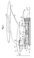
Figure 1 is a schematic section of part of a ducted fan gas turbine engine attached to an aircraft structure; -
Figure 2 is a schematic layout of an electrical component cooling arrangement in accordance with the present invention; -
Figure 3 is a section X-X through the electrical component cooling arrangement in accordance with the present invention. - Referring to
Figure 1 , a ducted fan gas turbine engine generally indicated at 10 has a principal and rotational axis XX. Theengine 10 is attached to theaircraft 9, usually to a wing or fuselage, via apylon 8. Normally, afuel tank 29 is housed in thewing 9. - The
engine 10 comprises, in axial flow series, anair intake 11, apropulsive fan 12, anintermediate pressure compressor 13, a high-pressure compressor 14,combustion equipment 15, a high-pressure turbine 16, and intermediate pressure turbine 17, a low-pressure turbine 18 and acore exhaust nozzle 19. Anacelle 21 generally surrounds theengine 10 and defines theintake 11, abypass duct 22 and a fanbypass exhaust nozzle 23. - The
gas turbine engine 10 works in the conventional manner so that air entering theintake 11 is accelerated by thefan 12 to produce two air flows: a first airflow A into theintermediate pressure compressor 13 and a second airflow B which passes through abypass duct 22 to provide propulsive thrust. Theintermediate pressure compressor 13 compresses the airflow A directed into it before delivering that air to thehigh pressure compressor 14 where further compression takes place. - The compressed air exhausted from the high-
pressure compressor 14 is directed into thecombustion equipment 15 where it is mixed with fuel and the mixture combusted. The resultant hot combustion products then expand through, and thereby drive the high, intermediate and low-pressure turbines nozzle 19 to provide additional propulsive thrust. The high, intermediate and low-pressure turbines intermediate pressure compressors fan 12 by suitable interconnecting shafts. - The
fan 12 is circumferentially surrounded by a structural member in the form of afan casing 24, which is supported by an annular array ofoutlet guide vanes 25. Engine accessories such as the EEC 26 and oil tank are mounted on thefan casing 24. - The
EEC 26 generates a substantial amount of heat and therefore requires cooling to prevent component failure. As mentioned in the pre-amble most engine electronics are air cooled and duct ambient air for this purpose. - Referring now to
Figures 2 and 3 , the present invention relates to using fuel to cool the EEC unit containing electronics. The cooling arrangement comprises theEEC 26 and afuel supply pipe 28 and apump 30;cooling pipes 32 connect thesupply pipe 28 to aninlet pipe 32 and anoutlet pipe 34 of theEEC 26. In this exemplary embodiment, the pump is a Venturi flow meter through which the fuel flowing along thesupply pipe 28 passes. Theoutlet pipe 34 is connected at athroat 36 of the Venturi 30 and with theinlet pipe 32 connected to thesupply pipe 28 upstream of the Venturi 30, a flow of fuel passes through theEEC 26. - The EEC 26 comprises a
body 38 enclosing an array ofelectronic components 40, such as capacitors, diodes, circuitry and microprocessors, and defines aninlet gallery 42 and anoutlet gallery 44 to which the inlet andoutlet pipes - The electrical component cooling arrangement also comprises a
controllable valve 48 for metering the flow of fuel into thebody 38 andtemperature gauge 50 for measuring the temperature of thecomponents 40, thevalve 48 being controlled to maintain a desired temperature of thecomponents 40. Thetemperature gauge 50 is attached to the body, but may be attached to an electrical component. A number temperature gauges may be attached to a number of components. Where the temperature of a component varies from its desired operation temperature more or less fuel may be supplied to the EEC. - When cooling of the
EEC 26 is required fuel will flow into theEEC 26 and directly over thecomponents 40. The chamber defined by thebody 38 is completely filled with fuel. Thefuel supply pipe 28 is connected to an aircraft fuel tank and routed to injectors in thecombustor assembly 15. Alternatively, thefuel supply pipe 28 is an additional connection to the aircraft fuel tank and the fuel from theoutlet 34 is passed back to the tank. In this case the Venturi 30 is replaced by aconvention pump 30. - During a typical flight cycle, the temperature of the fuel used (Kerosene) operates at a generally even temperature and this permits a stable operating environment to be established for the electronics. This use of fuel for controlling the environmental temperature is direct. Direct cooling involves flooding all or part of the unit and electronic components with the Kerosene. As Kerosene and other fuels are dielectric there is no danger of the electrical components causing a fire hazard.
- Due to the large thermal capacity of fuel (and other fluids compared to a gas), total immersion of the electronics provides the additional benefit of complete protection against fire attack external to the
EEC 26. - Thus the advantages of the present invention are maintenance of a uniform temperature of the electronic components, protection against internal and external fire, ability to further miniaturise electrical components and/or combine units due to enhanced cooling effectiveness.
- It should be appreciated by the skilled person that additional cooling of the electronic components or
body 38 may be achieved by the use of ribs, fins, turbulators, pedestals (e.g. 46) and rotating fluid flow fields as known in the art. - In the context of the present invention the word fuel is restricted to any dielectric petrochemical liquid.
Claims (9)
- An aircraft electrical component cooling arrangement comprises at least one electrical component (40) housed in a body (38) characterised in that fuel is passed through the body (38) and directly over the component (40).
- An aircraft electrical component cooling arrangement as claimed in claim 1 wherein the component (40) and body (38) are of an engine's (10) electronic control unit (26).
- An aircraft electrical component cooling arrangement as claimed in any one of claims 1-2 wherein the body (38) defines an inlet gallery (42) and an outlet gallery (44) for distribution of the fuel over the at least one electrical component (40).
- An aircraft electrical component cooling arrangement as claimed in any one of claims 1-3 wherein the aircraft comprises a fuel supply pipe (28) extending between a fuel tank (29) and a combustor assembly (15), an inlet pipe (32) connects from the fuel supply pipe (28) to the body (38) and the outlet pipe (34) connects the body (38) to the supply pipe (28).
- An aircraft electrical component cooling arrangement as claimed in claim 4 wherein a Venturi flow meter (30) is provided in the supply pipe (28), the Venturi flow meter comprising a throat (36) to which the outlet pipe (34) is connected.
- An aircraft electrical component cooling arrangement as claimed in any one of claims 1-3 wherein the arrangement comprises a pump (30) and a fuel supply pipe (28) extending from an aircraft fuel tank (29) to the body (38).
- An aircraft electrical component cooling arrangement as claimed in any one of claims 1-3 wherein the arrangement comprises a controllable valve (48) for metering the flow of fuel into the body (38) and temperature gauge (50) for measuring the temperature of the components (40), the valve (48) being controlled to maintain a desired temperature of the components (40).
- An aircraft electrical component cooling arrangement as claimed in any one of claims 1-7 wherein the body (38) is completely filled with fuel.
- A method of operating an aircraft electrical component cooling arrangement comprising at least one electrical component (40) housed in a body (38), the body (38) connected to a fuel supply pipe (28), method is characterised by passing fuel through the body (38) directly over the component (40) to cool the component (40).
Applications Claiming Priority (1)
| Application Number | Priority Date | Filing Date | Title |
|---|---|---|---|
| GBGB0622516.3A GB0622516D0 (en) | 2006-11-11 | 2006-11-11 | Cooling arrangement for electronics |
Publications (1)
| Publication Number | Publication Date |
|---|---|
| EP1921275A2 true EP1921275A2 (en) | 2008-05-14 |
Family
ID=37594759
Family Applications (1)
| Application Number | Title | Priority Date | Filing Date |
|---|---|---|---|
| EP07254261A Withdrawn EP1921275A2 (en) | 2006-11-11 | 2007-10-27 | Cooling arrangement for aircraft electronics |
Country Status (3)
| Country | Link |
|---|---|
| US (1) | US20080110593A1 (en) |
| EP (1) | EP1921275A2 (en) |
| GB (1) | GB0622516D0 (en) |
Cited By (1)
| Publication number | Priority date | Publication date | Assignee | Title |
|---|---|---|---|---|
| CN101839480A (en) * | 2009-02-03 | 2010-09-22 | 通用电气公司 | Burner assembly that uses in the gas-turbine unit and assemble method thereof |
Families Citing this family (4)
| Publication number | Priority date | Publication date | Assignee | Title |
|---|---|---|---|---|
| FR2932356B1 (en) * | 2008-06-10 | 2011-03-25 | Airbus France | HEAT DISSIPATION SYSTEM |
| US10618661B2 (en) * | 2015-02-23 | 2020-04-14 | Airbus Operations Gmbh | On-board removable container for cooling cargo materials and equipment in aircraft |
| US11499485B2 (en) * | 2020-02-10 | 2022-11-15 | Raytheon Technologies Corporation | Engine control device and methods thereof |
| US12473859B1 (en) * | 2024-07-02 | 2025-11-18 | Hamilton Sundstrand Corporation | Method and system for cooling of engine mounted components |
Family Cites Families (6)
| Publication number | Priority date | Publication date | Assignee | Title |
|---|---|---|---|---|
| US5111280A (en) * | 1988-11-10 | 1992-05-05 | Iversen Arthur H | Thermal management of power conditioning systems |
| US5692558A (en) * | 1996-07-22 | 1997-12-02 | Northrop Grumman Corporation | Microchannel cooling using aviation fuels for airborne electronics |
| GB2339081A (en) * | 1998-06-30 | 2000-01-12 | Cummins Engine Co Ltd | Cooling an engine control unit using fuel as coolant |
| US6352001B1 (en) * | 1999-08-30 | 2002-03-05 | General Electric Company | Non-iterative method for obtaining mass flow rate |
| JP2001107750A (en) * | 1999-10-05 | 2001-04-17 | Honda Motor Co Ltd | Aircraft gas turbine engine controller |
| US6396692B1 (en) * | 2000-07-27 | 2002-05-28 | Motorola, Inc. | Electronic control unit with integrated cooling module |
-
2006
- 2006-11-11 GB GBGB0622516.3A patent/GB0622516D0/en not_active Ceased
-
2007
- 2007-10-27 EP EP07254261A patent/EP1921275A2/en not_active Withdrawn
- 2007-10-30 US US11/978,621 patent/US20080110593A1/en not_active Abandoned
Cited By (1)
| Publication number | Priority date | Publication date | Assignee | Title |
|---|---|---|---|---|
| CN101839480A (en) * | 2009-02-03 | 2010-09-22 | 通用电气公司 | Burner assembly that uses in the gas-turbine unit and assemble method thereof |
Also Published As
| Publication number | Publication date |
|---|---|
| US20080110593A1 (en) | 2008-05-15 |
| GB0622516D0 (en) | 2006-12-20 |
Similar Documents
| Publication | Publication Date | Title |
|---|---|---|
| US8132398B2 (en) | Apparatus and method of operating a gas turbine engine at start-up | |
| US7174797B2 (en) | High temperature and pressure testing facility | |
| US10927763B2 (en) | Conditioned low pressure compressor compartment for gas turbine engine | |
| EP3121418A1 (en) | Cooling system for a turbine engine | |
| US9297304B2 (en) | Gas turbine engine system with bleed air powered auxiliary engine | |
| CN108071490A (en) | Cooling systems for turbine engines | |
| EP1921275A2 (en) | Cooling arrangement for aircraft electronics | |
| CN114439616A (en) | Combustion engine comprising a turbomachine | |
| EP3670874B1 (en) | Fuel system for heat engine | |
| EP4303416B1 (en) | Turbo expanders for turbine engines having hydrogen fuel systems | |
| EP4367373A2 (en) | Turbine engines having hydrogen fuel systems | |
| Shepard et al. | Design and development of the WR-21 intercooled recuperated (ICR) marine gas turbine | |
| US9494080B2 (en) | Fuel pumping unit | |
| Shepard et al. | Design and development of the WR-21 intercooled recuperated (ICR) marine gas turbine | |
| RU2349775C1 (en) | Nuclear gas-turbine aviation engine | |
| US20250334076A1 (en) | Jet engine thermal transport bus pumps | |
| Shook et al. | The aerodynamic performance of a high speed research centrifugal compressor facility | |
| CN118481837B (en) | Jet Engine Heat Transfer Bus Pumps | |
| US12571348B2 (en) | Fuel leak combustion assembly for igniting a gaseous fuel leaking from a potential leak location | |
| US20250250937A1 (en) | Cooling fluid control system and methods of operating a cooling fluid system for a turbine engine | |
| EP4563466A1 (en) | Combined nacelle anti-ice and wing anti-ice sytem | |
| San Benito Pastor et al. | Impact of Fuel Conditioning and Combustor Injection Temperature on a Hydrogen Turboprop | |
| Golden et al. | An experimental study of water injection into a Rolls-Royce model 250-C20B turboshaft gas turbine | |
| Meher-Homji et al. | Design Development and Implementation of a Compact 5000 SHP Gas Turbine Package for an Electromagnetic Gun System | |
| WO1998051912A1 (en) | Contained gas-turbine engine |
Legal Events
| Date | Code | Title | Description |
|---|---|---|---|
| PUAI | Public reference made under article 153(3) epc to a published international application that has entered the european phase |
Free format text: ORIGINAL CODE: 0009012 |
|
| AK | Designated contracting states |
Kind code of ref document: A2 Designated state(s): AT BE BG CH CY CZ DE DK EE ES FI FR GB GR HU IE IS IT LI LT LU LV MC MT NL PL PT RO SE SI SK TR |
|
| AX | Request for extension of the european patent |
Extension state: AL BA HR MK RS |
|
| STAA | Information on the status of an ep patent application or granted ep patent |
Free format text: STATUS: THE APPLICATION IS DEEMED TO BE WITHDRAWN |
|
| 18D | Application deemed to be withdrawn |
Effective date: 20130503 |