EP1921254A2 - Hoop seal with partial slot geometry - Google Patents
Hoop seal with partial slot geometry Download PDFInfo
- Publication number
- EP1921254A2 EP1921254A2 EP07021994A EP07021994A EP1921254A2 EP 1921254 A2 EP1921254 A2 EP 1921254A2 EP 07021994 A EP07021994 A EP 07021994A EP 07021994 A EP07021994 A EP 07021994A EP 1921254 A2 EP1921254 A2 EP 1921254A2
- Authority
- EP
- European Patent Office
- Prior art keywords
- rotor
- seal
- slot
- disk
- rotor disk
- Prior art date
- Legal status (The legal status is an assumption and is not a legal conclusion. Google has not performed a legal analysis and makes no representation as to the accuracy of the status listed.)
- Withdrawn
Links
Images



Classifications
-
- F—MECHANICAL ENGINEERING; LIGHTING; HEATING; WEAPONS; BLASTING
- F01—MACHINES OR ENGINES IN GENERAL; ENGINE PLANTS IN GENERAL; STEAM ENGINES
- F01D—NON-POSITIVE DISPLACEMENT MACHINES OR ENGINES, e.g. STEAM TURBINES
- F01D5/00—Blades; Blade-carrying members; Heating, heat-insulating, cooling or antivibration means on the blades or the members
- F01D5/30—Fixing blades to rotors; Blade roots ; Blade spacers
- F01D5/3007—Fixing blades to rotors; Blade roots ; Blade spacers of axial insertion type
- F01D5/3015—Fixing blades to rotors; Blade roots ; Blade spacers of axial insertion type with side plates
-
- F—MECHANICAL ENGINEERING; LIGHTING; HEATING; WEAPONS; BLASTING
- F01—MACHINES OR ENGINES IN GENERAL; ENGINE PLANTS IN GENERAL; STEAM ENGINES
- F01D—NON-POSITIVE DISPLACEMENT MACHINES OR ENGINES, e.g. STEAM TURBINES
- F01D11/00—Preventing or minimising internal leakage of working-fluid, e.g. between stages
- F01D11/001—Preventing or minimising internal leakage of working-fluid, e.g. between stages for sealing space between stator blade and rotor
-
- Y—GENERAL TAGGING OF NEW TECHNOLOGICAL DEVELOPMENTS; GENERAL TAGGING OF CROSS-SECTIONAL TECHNOLOGIES SPANNING OVER SEVERAL SECTIONS OF THE IPC; TECHNICAL SUBJECTS COVERED BY FORMER USPC CROSS-REFERENCE ART COLLECTIONS [XRACs] AND DIGESTS
- Y10—TECHNICAL SUBJECTS COVERED BY FORMER USPC
- Y10T—TECHNICAL SUBJECTS COVERED BY FORMER US CLASSIFICATION
- Y10T29/00—Metal working
- Y10T29/49—Method of mechanical manufacture
- Y10T29/49316—Impeller making
- Y10T29/4932—Turbomachine making
- Y10T29/49321—Assembling individual fluid flow interacting members, e.g., blades, vanes, buckets, on rotary support member
Definitions
- This invention generally relates to a bladed rotor assembly seal and a method of assembling a bladed rotor assembly seal.
- Turbine engines include rotor spools comprising one or several rotor disks. Fluid seals are included on the rotor disks for sealing against fixed elements of the turbine engine. The seals separate a lower pressure gas path air from higher pressure, cooling air.
- Each of the rotor blades includes a blade portion and a root portion that is mounted within the rotor disk. The root portion is received within a slot within the rotor disk to secure and position the rotor blade.
- the slots for each of the rotor blades are formed by a secondary machining operation to provide the desired fit between each of the rotor blades and the rotor disk.
- the slot extends entirely through the rotor disk including the seal.
- the resulting seal on the rotor disk is therefore interrupted at each position where a rotor blade slot is formed.
- Each rotor blade is then formed to include a surface that matches the seal profile. Because each rotor blade is matched to the seal profile, the complex seal profile is manufactured once for the rotor disk and again for each of the rotor disks. Therefore, the interfitting of each rotor blade creates a seal that comprises rotor disk portions and rotor blade portions segmented and interrupted about the circumference of the rotor disk.
- each of the rotor blades and the rotor disk is held to close tolerances to provide the desired seal profile through each rotor blade and the rotor disk. As with any mating interface, some undesirable gaps or spacing will occur between a rotor blade and the rotor disk. Gaps between the rotor disk and the rotor blade can result in less than desired seal performance.
- An example rotor blade assembly includes a slot for mounting an example rotor blade that extends partially through a rotor disk and a continuous uninterrupted hoop seal that extends about the circumference of the rotor disk.
- the example rotor disk includes the seal having at least one seal edge disposed concentrically about the rotor disk that correspond to abradable structures for sealing and containing air flow about the rotor disk.
- the example seal is an integral part of the rotor disk.
- the example slot receives a root portion of a rotor blade but does not extend through the seal.
- additional rigidity and strength are realized as compared to conventional segmented seals that utilize portions of a rotor blade to complete the seal,
- the increased rigidity and strength provided by the full hoop structure provides for the reduction in material and physical dimensions without compromising desired performance of the seal.
- Figure 1 is a simplified schematic view of an example turbine engine 10 that includes a fan 12 for pulling air into the turbine engine 10.
- the air pulled into the turbine engine 10 is drawn through a low pressure compressor 14 and a high pressure compressor 16.
- Compressed air is fed to a combustor 18, mixed with fuel and ignited to produce a high velocity gas stream.
- the high velocity gas stream drives a high pressure turbine 20 and a low pressure turbine 22 and is exhausted through an exhaust nozzle 24.
- the high pressure turbine 20 and low pressure turbine 22 comprise a plurality of bladed rotor assemblies that each includes a plurality of blades mounted about an outer rim of a rotor disk. Between the bladed rotor assemblies are fixed structures and seals that control and contain the flow of exhaust gases and compressed air to provide the desired engine performance.
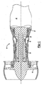
- an example rotor disk 26 includes a seal 28 that is disposed proximate a fixed structure 35.
- the fixed structure 35 supports abradable honeycomb material 44 that correspond to knife edges 30 and 32 of the seal 28.
- the knife edges 30 and 32 are disposed concentrically with each other to provide the desired sealing of air flow about the rotor disk 26.
- the seal edges 30 and 32 interact with the abradable honeycomb material 44 to provide the desired seal.
- the seal 28 rotates with the rotor disk 26 while the abradable honeycomb material 44 remains stationary.
- the bladed rotor disk 26 provides for the support of a plurality of rotor blades 34.
- Each of the rotor blades 34 includes a root portion 36 that is received within an axial slot 50 of the rotor disk 26.
- the slot 50 extends axially through the rotor disk 26, but not the seal 28. Because the slot 50 does not extend through the seal 28, the seal 28 is a continuous uninterrupted hoop structure that extends about the circumference of the rotor disk 26.
- the knife edges 30, 32 remain uninterrupted because the slot 50 extends only partially through the rotor disk 26.
- the uninterrupted structure of the seal 28 provides increased strength and improved leakage restriction when compared to interrupted and segmented seals 28.
- the slot 50 for receiving the rotor portion 36 of the example rotor blade 34 extends from a second side 42 of the rotor disk to a first side 40. Accordingly, a portion of the front side 42 opens into the slot 50. However, the slot 50 does not extend into the seal 28.
- the root portion 36 of the example rotor blade 34 is visible in the example slot 50 as illustrated but does not extend into the seal 28.
- the root portion 36 includes a profile shaped to match a portion of the first side 40 of the rotor disk 26 that does not include the seal 28, Because the seal profile is not required to be reproduced in the root portion 36 of the rotor blade 34, manufacturing of the rotor blade 34 is simplified,
- the example rotor disk 26 includes a disk rim 46 that is disposed between the first side 40 and the second side 42.
- the disk rim 46 is that perimeter surface that is substantially transverse and between the first and second sides 40, 42.
- the first side 40 includes the seal 28.
- the slot 50 extends downward radially from the disk rim 46 to a point below the seal 28 such that a portion of the example root portion 36 is exposed through the first side 40. However, the root portion 36 does not extend axially through the seal 28.
- the example slot 50 is shown without the rotor blade 34 installed and extends from an opening exposed on the second side 42 toward the first side 40 of the rotor disk 26.
- the example slot 50 includes a partial opening 52 on the first side 40 that does not break through the continuous seal 28.
- the example slot 50 includes an inner profile 54 that provides for positioning and securing the rotor blade 34 in a desired position during engine operation.
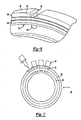
- the slot 50 is illustrated from the first side 40 of the example rotor disk 26.
- the seal 28 remains as an integral, continuous and uninterrupted structure disposed on the first side 40.
- additional rigidity, strength and improved leakage restriction are realized as compared to conventional segmented seals that utilize portions of a rotor blade to complete the seal.
- the increased rigidity and strength provided by the full hoop structure provides for the reduction in material and physical dimensions without sacrificing the desired performance of the seal 28.
- Fabrication of the rotor disk assembly includes the steps of forming the rotor disk 26 to include the first side 40 and the second side 42.
- the forming step further includes forming the rotor disk 26 to include the uninterrupted concentric seal 28 on the first side 40.
- the example concentric seal 28 includes the first seal edge 30 and the second seal edge 32.
- the example concentric seal 28 includes two knife edges, the number of knife edges may vary depending on the pressure ratio between the combustion gases and the cooling air.
- the rotor disk 26 is formed utilizing materials such as powdered Nickel that provide desired strength and durability characteristics for the environment encountered during engine operation.
- the formed rotor disk 26 includes the disk rim 46 that is the periphery of the rotor disk 26 and that is disposed between the first side 40 and the second side.
- the slot 50 is cut along the rotor disk 26 periphery and is open to the second side 42 opposite the seal 28.
- the slot 50 is cut from the second side 42 toward the first side 40, to a point desired to provide a desired fit of the rotor blade 34. However, no portion of the slot 50 extends entirely through the seal 28. Some portions of the slot 50 may extend into portions of the seal 28, but no portion extends through any of the seal edges 30, 32.
- the knife edges 30 and 32 remain a single uninterrupted continuous hoop concentric about the rotor disk 26.
- the slot 50 is fabricated utilizing methods as are known for example with the use of a cutting tool.
- the example slot 50 is open along the disk rim 46. Although a single slot 50 is illustrated and discussed, a plurality of slots 50 are formed into the rotor disk 26 as are need to support the desired number of rotor blades 34.
- the slot 50 is formed to include the complementary-shaped inner profile 54 that receives the rotor blade 34 from the second side 42.
- Each rotor blade 34 is slid from the second side 42 into the slot 50 toward the first side 40.
- the seal 28 remains an integral portion of the rotor disk 26 the rotor blade 34 is pushed forward to abut a rear surface of the seal 28. Abutting contact between the rotor blade 34 and the seal 28 provides an axial stop for maintaining the rotor blade 34 within the rotor disk 26.
- a cover plate 38 is attached to the second side 42 of the rotor disk 26 to secure the rotor blade 34 within the rotor disk 26.
- the integrally formed continuous seal 28 thereby provides for the elimination of an additional cover or mounting device for maintaining the rotor blade 34 within the rotor disk 26.
- the seal 28 includes complete uninterrupted hoop knife edges 30 and 32.
- the seal 28 may then be fabricated as thinner structures due to the increased strength and durability provided by the continuous hoop.
- the continuous seal 28 thereby provides improved leakage restriction performance with smoother, lighter and thinner knife edges that are not cantilevered in short sections about the rotor disk and from each of a plurality of rotor blades.
Landscapes
- Engineering & Computer Science (AREA)
- Mechanical Engineering (AREA)
- General Engineering & Computer Science (AREA)
- Turbine Rotor Nozzle Sealing (AREA)
- Sealing Devices (AREA)
Abstract
Description
- This invention generally relates to a bladed rotor assembly seal and a method of assembling a bladed rotor assembly seal.
- Turbine engines include rotor spools comprising one or several rotor disks. Fluid seals are included on the rotor disks for sealing against fixed elements of the turbine engine. The seals separate a lower pressure gas path air from higher pressure, cooling air. Each of the rotor blades includes a blade portion and a root portion that is mounted within the rotor disk. The root portion is received within a slot within the rotor disk to secure and position the rotor blade.
- The slots for each of the rotor blades are formed by a secondary machining operation to provide the desired fit between each of the rotor blades and the rotor disk. The slot extends entirely through the rotor disk including the seal. The resulting seal on the rotor disk is therefore interrupted at each position where a rotor blade slot is formed. Each rotor blade is then formed to include a surface that matches the seal profile. Because each rotor blade is matched to the seal profile, the complex seal profile is manufactured once for the rotor disk and again for each of the rotor disks. Therefore, the interfitting of each rotor blade creates a seal that comprises rotor disk portions and rotor blade portions segmented and interrupted about the circumference of the rotor disk.
- The interface between each of the rotor blades and the rotor disk is held to close tolerances to provide the desired seal profile through each rotor blade and the rotor disk. As with any mating interface, some undesirable gaps or spacing will occur between a rotor blade and the rotor disk. Gaps between the rotor disk and the rotor blade can result in less than desired seal performance.
- An example rotor blade assembly includes a slot for mounting an example rotor blade that extends partially through a rotor disk and a continuous uninterrupted hoop seal that extends about the circumference of the rotor disk.
- The example rotor disk includes the seal having at least one seal edge disposed concentrically about the rotor disk that correspond to abradable structures for sealing and containing air flow about the rotor disk. The example seal is an integral part of the rotor disk.
- The example slot receives a root portion of a rotor blade but does not extend through the seal. As the seal remains an uninterrupted full hoop about the circumference of the rotor disk, additional rigidity and strength are realized as compared to conventional segmented seals that utilize portions of a rotor blade to complete the seal, The increased rigidity and strength provided by the full hoop structure provides for the reduction in material and physical dimensions without compromising desired performance of the seal.
- These and other features of the present invention can be best understood from the following specification and drawings, the following of which is a brief description.
-
- Figure 1 is a simplified schematic view of an example turbine engine.
- Figure 2 is a schematic view of an example rotor disk assembly.
- Figure 3 is a perspective view of a portion of the example rotor disk assembly.
- Figure 4 is another perspective view of a portion of the example rotor disk assembly.
- Figure 5 is a view of an example slot within the example rotor disk assembly.
- Figure 6 is a front view of the example slot within the example rotor disk assembly.
- Figure 7 is a schematic front view of the example rotor disk assembly.
- Figure 8 is a schematic view of assembly steps for the example rotor disk assembly.
- Figure 1 is a simplified schematic view of an
example turbine engine 10 that includes afan 12 for pulling air into theturbine engine 10. The air pulled into theturbine engine 10 is drawn through a low pressure compressor 14 and ahigh pressure compressor 16. Compressed air is fed to acombustor 18, mixed with fuel and ignited to produce a high velocity gas stream. The high velocity gas stream drives ahigh pressure turbine 20 and alow pressure turbine 22 and is exhausted through anexhaust nozzle 24. - The
high pressure turbine 20 andlow pressure turbine 22 comprise a plurality of bladed rotor assemblies that each includes a plurality of blades mounted about an outer rim of a rotor disk. Between the bladed rotor assemblies are fixed structures and seals that control and contain the flow of exhaust gases and compressed air to provide the desired engine performance. - Referring to Figure 2, an
example rotor disk 26 includes aseal 28 that is disposed proximate afixed structure 35. Thefixed structure 35 supportsabradable honeycomb material 44 that correspond toknife edges seal 28. Theknife edges rotor disk 26. During operation, theseal edges abradable honeycomb material 44 to provide the desired seal. Theseal 28 rotates with therotor disk 26 while theabradable honeycomb material 44 remains stationary. - The
bladed rotor disk 26 provides for the support of a plurality ofrotor blades 34. Each of therotor blades 34 includes aroot portion 36 that is received within anaxial slot 50 of therotor disk 26. Theslot 50 extends axially through therotor disk 26, but not theseal 28. Because theslot 50 does not extend through theseal 28, theseal 28 is a continuous uninterrupted hoop structure that extends about the circumference of therotor disk 26. - Referring to Figure 3, the
knife edges slot 50 extends only partially through therotor disk 26. The uninterrupted structure of theseal 28 provides increased strength and improved leakage restriction when compared to interrupted and segmentedseals 28. - The
slot 50 for receiving therotor portion 36 of theexample rotor blade 34 extends from asecond side 42 of the rotor disk to afirst side 40. Accordingly, a portion of thefront side 42 opens into theslot 50. However, theslot 50 does not extend into theseal 28. Theroot portion 36 of theexample rotor blade 34 is visible in theexample slot 50 as illustrated but does not extend into theseal 28. Theroot portion 36 includes a profile shaped to match a portion of thefirst side 40 of therotor disk 26 that does not include theseal 28, Because the seal profile is not required to be reproduced in theroot portion 36 of therotor blade 34, manufacturing of therotor blade 34 is simplified, - Referring to Figure 4, the
example rotor disk 26 includes adisk rim 46 that is disposed between thefirst side 40 and thesecond side 42. Thedisk rim 46 is that perimeter surface that is substantially transverse and between the first andsecond sides first side 40 includes theseal 28. Theslot 50 extends downward radially from thedisk rim 46 to a point below theseal 28 such that a portion of theexample root portion 36 is exposed through thefirst side 40. However, theroot portion 36 does not extend axially through theseal 28. - Referring to Figure 5, the
example slot 50 is shown without therotor blade 34 installed and extends from an opening exposed on thesecond side 42 toward thefirst side 40 of therotor disk 26. Theexample slot 50 includes apartial opening 52 on thefirst side 40 that does not break through thecontinuous seal 28. Theexample slot 50 includes aninner profile 54 that provides for positioning and securing therotor blade 34 in a desired position during engine operation. - Referring to Figure 6, the
slot 50 is illustrated from thefirst side 40 of theexample rotor disk 26. Theseal 28 remains as an integral, continuous and uninterrupted structure disposed on thefirst side 40. As theseal 28 remains an uninterrupted full hoop about the circumference of therotor disk 26, additional rigidity, strength and improved leakage restriction are realized as compared to conventional segmented seals that utilize portions of a rotor blade to complete the seal. The increased rigidity and strength provided by the full hoop structure provides for the reduction in material and physical dimensions without sacrificing the desired performance of theseal 28. - Fabrication of the rotor disk assembly includes the steps of forming the
rotor disk 26 to include thefirst side 40 and thesecond side 42. The forming step further includes forming therotor disk 26 to include the uninterruptedconcentric seal 28 on thefirst side 40. The exampleconcentric seal 28 includes thefirst seal edge 30 and thesecond seal edge 32. Although the exampleconcentric seal 28 includes two knife edges, the number of knife edges may vary depending on the pressure ratio between the combustion gases and the cooling air. - The
rotor disk 26 is formed utilizing materials such as powdered Nickel that provide desired strength and durability characteristics for the environment encountered during engine operation. The formedrotor disk 26 includes thedisk rim 46 that is the periphery of therotor disk 26 and that is disposed between thefirst side 40 and the second side. - The
slot 50 is cut along therotor disk 26 periphery and is open to thesecond side 42 opposite theseal 28. Theslot 50 is cut from thesecond side 42 toward thefirst side 40, to a point desired to provide a desired fit of therotor blade 34. However, no portion of theslot 50 extends entirely through theseal 28. Some portions of theslot 50 may extend into portions of theseal 28, but no portion extends through any of the seal edges 30, 32. - Referring to Figure 7 with continuing references to Figure 6, the knife edges 30 and 32 remain a single uninterrupted continuous hoop concentric about the
rotor disk 26. Theslot 50 is fabricated utilizing methods as are known for example with the use of a cutting tool. Theexample slot 50 is open along thedisk rim 46. Although asingle slot 50 is illustrated and discussed, a plurality ofslots 50 are formed into therotor disk 26 as are need to support the desired number ofrotor blades 34. - Referring to Figure 8, the
slot 50 is formed to include the complementary-shapedinner profile 54 that receives therotor blade 34 from thesecond side 42. Eachrotor blade 34 is slid from thesecond side 42 into theslot 50 toward thefirst side 40. As theseal 28 remains an integral portion of therotor disk 26 therotor blade 34 is pushed forward to abut a rear surface of theseal 28. Abutting contact between therotor blade 34 and theseal 28 provides an axial stop for maintaining therotor blade 34 within therotor disk 26. Acover plate 38 is attached to thesecond side 42 of therotor disk 26 to secure therotor blade 34 within therotor disk 26. The integrally formedcontinuous seal 28 thereby provides for the elimination of an additional cover or mounting device for maintaining therotor blade 34 within therotor disk 26. - Accordingly, as the
slot 50 extends only partially through therotor disk 26, theseal 28 includes complete uninterrupted hoop knife edges 30 and 32. Theseal 28 may then be fabricated as thinner structures due to the increased strength and durability provided by the continuous hoop. Thecontinuous seal 28 thereby provides improved leakage restriction performance with smoother, lighter and thinner knife edges that are not cantilevered in short sections about the rotor disk and from each of a plurality of rotor blades. - Although a preferred embodiment of this invention has been disclosed, a worker of ordinary skill in this art would recognize that certain modifications would come within the scope of this invention. For that reason, the following claims should be studied to determine the true scope and content of this invention.
Claims (14)
- A bladed rotor assembly comprising;a rotor disk (26) defining a disk rim (46) and having a rotor blade (34) mounted to the disk rim (46);a seal (28) disposed on a first side (40) of the rotor disk (26) including a continuous circumferential surface; anda slot (50) open on a second side (42) and extending partially toward the first side (40) such that the slot (50) does not extend through the seal (28).
- The bladed rotor assembly as recited in claim 1, wherein each of the plurality of rotor blades (34) comprise a root portion (36) received within the slot (50).
- The bladed rotor assembly as recited in claim 2, including a cover plate (38) attached to the second side (42) over the open slot (50) to secure the rotor blade (34) within the slot.
- The bladed rotor assembly as recited in claim 2 or claim 3, wherein the root portion (36) of the rotor blade (34) includes a forward surface that matches a profile of the second side (42) of the rotor disk (26).
- The bladed rotor assembly as recited in any preceding claim, wherein the (28) seal comprises at least one concentric knife edge (30,32).
- The bladed rotor assembly as recited in any preceding claim, wherein the slot (50) is disposed in the disk rim (46).
- The bladed rotor assembly as recited in any preceding claim, wherein the seal (28) comprises a profile defined within the first side (40).
- A method of fabricating a bladed rotor assembly comprising the steps of:a) forming a rotor disk (26) including a first side (40) and a second side (42);b) forming an uninterrupted concentric seal (28) on a first side (40) of the rotor disk (26);c) forming a slot (50) from the second side (42) partially through the rotor disk (26) toward the first side (40) such that the seal (28) is not interrupted; andd) securing a rotor blade (34) within the slot (50).
- The method as recited in claim 8, wherein step c) comprises cutting a slot (50) from the second side (42) partially through to the first side (40) of the rotor disk (26).
- The method as recited in claim 8 or 9, wherein the rotor disk (26) includes a disk rim (46) between the first side (40) and the second side (42) and step c) comprises cutting the slot (50) in the disk rim (46).
- The method as recited in any of claims 8-10, wherein step b) comprises forming at least one knife edge (30,32) concentric with the rotor disk (26) and extending from the first side (40) of the rotor disk (26).
- The method as recited in any of claims 8-11, including the step of forming a side of the rotor blade (34) to match the first side (40) of the rotor disk (26).
- The method as recited in any of claims 8-12, wherein step d) comprises axially holding the rotor blade (34) within the slot (50) with the seal (28) on the first side (40).
- The method as recited in any of claims 8-13, wherein step d) comprises attaching a cover plate (38) to the second side (42) of the rotor disk (26) for securing the rotor blade (34) within the slot (50).
Applications Claiming Priority (1)
| Application Number | Priority Date | Filing Date | Title |
|---|---|---|---|
| US11/598,486 US7927069B2 (en) | 2006-11-13 | 2006-11-13 | Hoop seal with partial slot geometry |
Publications (2)
| Publication Number | Publication Date |
|---|---|
| EP1921254A2 true EP1921254A2 (en) | 2008-05-14 |
| EP1921254A3 EP1921254A3 (en) | 2011-11-02 |
Family
ID=39092072
Family Applications (1)
| Application Number | Title | Priority Date | Filing Date |
|---|---|---|---|
| EP07021994A Withdrawn EP1921254A3 (en) | 2006-11-13 | 2007-11-13 | Hoop seal with partial slot geometry |
Country Status (2)
| Country | Link |
|---|---|
| US (1) | US7927069B2 (en) |
| EP (1) | EP1921254A3 (en) |
Cited By (1)
| Publication number | Priority date | Publication date | Assignee | Title |
|---|---|---|---|---|
| WO2015082808A1 (en) * | 2013-12-06 | 2015-06-11 | Turbomeca | Bladed rotor |
Families Citing this family (10)
| Publication number | Priority date | Publication date | Assignee | Title |
|---|---|---|---|---|
| US8205335B2 (en) * | 2007-06-12 | 2012-06-26 | United Technologies Corporation | Method of repairing knife edge seals |
| US8162615B2 (en) * | 2009-03-17 | 2012-04-24 | United Technologies Corporation | Split disk assembly for a gas turbine engine |
| US9097129B2 (en) | 2012-05-31 | 2015-08-04 | United Technologies Corporation | Segmented seal with ship lap ends |
| US9366145B2 (en) | 2012-08-24 | 2016-06-14 | United Technologies Corporation | Turbine engine rotor assembly |
| EP2767678A1 (en) * | 2013-02-19 | 2014-08-20 | Siemens Aktiengesellschaft | Bucket wheel and method for fabricating a bucket |
| US20160230579A1 (en) * | 2015-02-06 | 2016-08-11 | United Technologies Corporation | Rotor disk sealing and blade attachments system |
| US10358932B2 (en) | 2015-06-29 | 2019-07-23 | United Technologies Corporation | Segmented non-contact seal assembly for rotational equipment |
| US10794208B2 (en) | 2015-07-08 | 2020-10-06 | Raytheon Technologies Corporation | Non-contact seal assembly for rotational equipment with linkage between adjacent rotors |
| US10094241B2 (en) | 2015-08-19 | 2018-10-09 | United Technologies Corporation | Non-contact seal assembly for rotational equipment |
| US10107126B2 (en) | 2015-08-19 | 2018-10-23 | United Technologies Corporation | Non-contact seal assembly for rotational equipment |
Citations (1)
| Publication number | Priority date | Publication date | Assignee | Title |
|---|---|---|---|---|
| US20050265849A1 (en) | 2004-05-28 | 2005-12-01 | Melvin Bobo | Turbine blade retainer seal |
Family Cites Families (8)
| Publication number | Priority date | Publication date | Assignee | Title |
|---|---|---|---|---|
| GB1318654A (en) | 1970-12-05 | 1973-05-31 | Secr Defence | Bladed rotors |
| US4558988A (en) * | 1983-12-22 | 1985-12-17 | United Technologies Corporation | Rotor disk cover plate attachment |
| US4767276A (en) * | 1986-12-19 | 1988-08-30 | General Electric Company | Retainer ring |
| GB2294732A (en) * | 1994-11-05 | 1996-05-08 | Rolls Royce Plc | Integral disc seal for turbomachine |
| JPH10252412A (en) | 1997-03-12 | 1998-09-22 | Mitsubishi Heavy Ind Ltd | Gas turbine sealing device |
| US6077035A (en) * | 1998-03-27 | 2000-06-20 | Pratt & Whitney Canada Corp. | Deflector for controlling entry of cooling air leakage into the gaspath of a gas turbine engine |
| US6190131B1 (en) * | 1999-08-31 | 2001-02-20 | General Electric Co. | Non-integral balanced coverplate and coverplate centering slot for a turbine |
| US6439851B1 (en) * | 2000-12-21 | 2002-08-27 | United Technologies Corporation | Reduced stress rotor blade and disk assembly |
-
2006
- 2006-11-13 US US11/598,486 patent/US7927069B2/en not_active Expired - Fee Related
-
2007
- 2007-11-13 EP EP07021994A patent/EP1921254A3/en not_active Withdrawn
Patent Citations (1)
| Publication number | Priority date | Publication date | Assignee | Title |
|---|---|---|---|---|
| US20050265849A1 (en) | 2004-05-28 | 2005-12-01 | Melvin Bobo | Turbine blade retainer seal |
Cited By (5)
| Publication number | Priority date | Publication date | Assignee | Title |
|---|---|---|---|---|
| WO2015082808A1 (en) * | 2013-12-06 | 2015-06-11 | Turbomeca | Bladed rotor |
| FR3014477A1 (en) * | 2013-12-06 | 2015-06-12 | Turbomeca | ROTOR IN AUBES |
| CN105814281A (en) * | 2013-12-06 | 2016-07-27 | 涡轮梅坎公司 | Bladed rotor |
| CN105814281B (en) * | 2013-12-06 | 2018-05-25 | 涡轮梅坎公司 | Bladed rotor |
| US10858946B2 (en) | 2013-12-06 | 2020-12-08 | Safran Helicopter Engines | Bladed rotor |
Also Published As
| Publication number | Publication date |
|---|---|
| US20080112811A1 (en) | 2008-05-15 |
| US7927069B2 (en) | 2011-04-19 |
| EP1921254A3 (en) | 2011-11-02 |
Similar Documents
| Publication | Publication Date | Title |
|---|---|---|
| EP1921254A2 (en) | Hoop seal with partial slot geometry | |
| EP4012167B1 (en) | Passive transpirational flow acoustically lined guide vane | |
| EP3693553B1 (en) | Feather seal assembly with leakage metering | |
| EP2093384B2 (en) | Filter system for blade outer air seal | |
| EP3473811B1 (en) | Fan blade platform | |
| US11408349B2 (en) | Active flow control transpirational flow acoustically lined guide vane | |
| US9033657B2 (en) | Gas turbine engine including lift-off finger seals, lift-off finger seals, and method for the manufacture thereof | |
| US9797262B2 (en) | Split damped outer shroud for gas turbine engine stator arrays | |
| EP3063379B1 (en) | Radial seal with offset relief cut | |
| EP1924758B1 (en) | Vane assembly with outer grommets | |
| EP1930552B1 (en) | Turbine assembly to facilitate reducing losses in turbine engines | |
| CA2622017C (en) | Vane assembly with improved vane roots | |
| EP2971568B1 (en) | Flap seal for a fan of a gas turbine engine | |
| EP3181945B1 (en) | Damper seal installation features | |
| JP2009508031A (en) | Vane assembly with grommets | |
| CN113006884A (en) | Turbine nozzle with angled inner band flange | |
| US10801361B2 (en) | System and method for HPT disk over speed prevention | |
| EP3896260B1 (en) | Seal element for sealing a joint between a rotor blade and a rotor disk | |
| US6729842B2 (en) | Methods and apparatus to reduce seal rubbing within gas turbine engines | |
| US20240141797A1 (en) | Rotary machine seal having a wear protection assembly with an abradable covering | |
| EP4474619A1 (en) | Turbine vane baffle chimney | |
| WO2014092909A1 (en) | Multi-piece blade for gas turbine engine | |
| CA2597443A1 (en) | Vane assembly with improved vane roots |
Legal Events
| Date | Code | Title | Description |
|---|---|---|---|
| PUAI | Public reference made under article 153(3) epc to a published international application that has entered the european phase |
Free format text: ORIGINAL CODE: 0009012 |
|
| AK | Designated contracting states |
Kind code of ref document: A2 Designated state(s): AT BE BG CH CY CZ DE DK EE ES FI FR GB GR HU IE IS IT LI LT LU LV MC MT NL PL PT RO SE SI SK TR |
|
| AX | Request for extension of the european patent |
Extension state: AL BA HR MK RS |
|
| PUAL | Search report despatched |
Free format text: ORIGINAL CODE: 0009013 |
|
| AK | Designated contracting states |
Kind code of ref document: A3 Designated state(s): AT BE BG CH CY CZ DE DK EE ES FI FR GB GR HU IE IS IT LI LT LU LV MC MT NL PL PT RO SE SI SK TR |
|
| AX | Request for extension of the european patent |
Extension state: AL BA HR MK RS |
|
| RIC1 | Information provided on ipc code assigned before grant |
Ipc: F01D 11/00 20060101ALI20110928BHEP Ipc: F01D 5/30 20060101ALI20110928BHEP Ipc: F01D 5/06 20060101AFI20110928BHEP |
|
| 17P | Request for examination filed |
Effective date: 20120330 |
|
| AKX | Designation fees paid |
Designated state(s): DE GB |
|
| STAA | Information on the status of an ep patent application or granted ep patent |
Free format text: STATUS: THE APPLICATION HAS BEEN WITHDRAWN |
|
| 18W | Application withdrawn |
Effective date: 20140122 |