EP1920559B1 - A module for the distribution of communications signals - Google Patents
A module for the distribution of communications signals Download PDFInfo
- Publication number
- EP1920559B1 EP1920559B1 EP06775951A EP06775951A EP1920559B1 EP 1920559 B1 EP1920559 B1 EP 1920559B1 EP 06775951 A EP06775951 A EP 06775951A EP 06775951 A EP06775951 A EP 06775951A EP 1920559 B1 EP1920559 B1 EP 1920559B1
- Authority
- EP
- European Patent Office
- Prior art keywords
- module
- signals
- module according
- signal
- connectors
- Prior art date
- Legal status (The legal status is an assumption and is not a legal conclusion. Google has not performed a legal analysis and makes no representation as to the accuracy of the status listed.)
- Active
Links
Images


Classifications
-
- H—ELECTRICITY
- H04—ELECTRIC COMMUNICATION TECHNIQUE
- H04L—TRANSMISSION OF DIGITAL INFORMATION, e.g. TELEGRAPHIC COMMUNICATION
- H04L12/00—Data switching networks
- H04L12/28—Data switching networks characterised by path configuration, e.g. LAN [Local Area Networks] or WAN [Wide Area Networks]
- H04L12/2803—Home automation networks
- H04L12/2838—Distribution of signals within a home automation network, e.g. involving splitting/multiplexing signals to/from different paths
-
- H—ELECTRICITY
- H04—ELECTRIC COMMUNICATION TECHNIQUE
- H04L—TRANSMISSION OF DIGITAL INFORMATION, e.g. TELEGRAPHIC COMMUNICATION
- H04L12/00—Data switching networks
- H04L12/28—Data switching networks characterised by path configuration, e.g. LAN [Local Area Networks] or WAN [Wide Area Networks]
- H04L12/2801—Broadband local area networks
-
- H—ELECTRICITY
- H04—ELECTRIC COMMUNICATION TECHNIQUE
- H04L—TRANSMISSION OF DIGITAL INFORMATION, e.g. TELEGRAPHIC COMMUNICATION
- H04L12/00—Data switching networks
- H04L12/28—Data switching networks characterised by path configuration, e.g. LAN [Local Area Networks] or WAN [Wide Area Networks]
- H04L12/2803—Home automation networks
-
- H—ELECTRICITY
- H04—ELECTRIC COMMUNICATION TECHNIQUE
- H04M—TELEPHONIC COMMUNICATION
- H04M11/00—Telephonic communication systems specially adapted for combination with other electrical systems
- H04M11/06—Simultaneous speech and data transmission, e.g. telegraphic transmission over the same conductors
- H04M11/062—Simultaneous speech and data transmission, e.g. telegraphic transmission over the same conductors using different frequency bands for speech and other data
-
- H—ELECTRICITY
- H04—ELECTRIC COMMUNICATION TECHNIQUE
- H04N—PICTORIAL COMMUNICATION, e.g. TELEVISION
- H04N21/00—Selective content distribution, e.g. interactive television or video on demand [VOD]
- H04N21/40—Client devices specifically adapted for the reception of or interaction with content, e.g. set-top-box [STB]; Operations thereof
- H04N21/41—Structure of client; Structure of client peripherals
- H04N21/426—Internal components of the client ; Characteristics thereof
- H04N21/42676—Internal components of the client ; Characteristics thereof for modulating an analogue carrier signal to encode digital information or demodulating it to decode digital information, e.g. ADSL or cable modem
-
- H—ELECTRICITY
- H04—ELECTRIC COMMUNICATION TECHNIQUE
- H04L—TRANSMISSION OF DIGITAL INFORMATION, e.g. TELEGRAPHIC COMMUNICATION
- H04L12/00—Data switching networks
- H04L12/28—Data switching networks characterised by path configuration, e.g. LAN [Local Area Networks] or WAN [Wide Area Networks]
- H04L12/2803—Home automation networks
- H04L2012/284—Home automation networks characterised by the type of medium used
- H04L2012/2841—Wireless
-
- H—ELECTRICITY
- H04—ELECTRIC COMMUNICATION TECHNIQUE
- H04L—TRANSMISSION OF DIGITAL INFORMATION, e.g. TELEGRAPHIC COMMUNICATION
- H04L12/00—Data switching networks
- H04L12/28—Data switching networks characterised by path configuration, e.g. LAN [Local Area Networks] or WAN [Wide Area Networks]
- H04L12/2803—Home automation networks
- H04L2012/284—Home automation networks characterised by the type of medium used
- H04L2012/2845—Telephone line
Definitions
- the invention relates to a module for the distribution of communications signals in a building or the like which is provided with a number of connectors that are connected to the module via a wiring network in the building, said wiring network comprising a cable with a number of pairs of twisted wires.
- the object of the invention is to provide a module for the distribution of communication signals and multimedia signals that can be distributed simultaneously via a shared wiring network, and wherein the multimedia signal can be transmitted effectively across the distances that are typical for a building.
- the module comprises signal outputs that are connected to respective terminals in some connectors and each of which comprises means for individual adaptation of a respective output signal.
- the invention provides both propagation via a shared wiring network and optimal distribution of the signal. Due to the adjustable optimal transmission conditions it is also accomplished by the invention that all types of signals can be propagated simultaneously in the cable which Is connected to a respective connector and which may comprise eg four pairs of twisted wires.
- the same multimedia signal is often to be emitted to several connectors, and in accordance with a preferred embodiment the signal outputs that have means for individual adaptation are permanently wired to the respective connectors. Thereby the module is ensured against users subsequently disturbing the adaptation.
- the arrangement known from WO 00/31953 is based on a patch panel and an amplifier for converting a multimedia signal that can be emitted to a connector. Individual adaptation is not possible, but even If that had been the case, it would have been destroyed when the user moves the patch cable.
- the individual adaptation comprises an Individual adjustment of the amplifier characteristic of each signal output and preferably also comprises a conversion of the signal from unbalanced to balanced form.
- a back-conversion is to be performed, which is typically performed in a connecting cable between a connector and a receiver apparatus.
- the invention is further suitable for use in connection with the prior art known per se for turning off an output amplifier In case a receiver apparatus is not connected to the connector. This is preferably done by detection of a DC signal level at the respective output on the module.
- the module according to the invention can be combined with what is also known from WO 00/31953 ; viz that the module has input signals for other telephony and data signals that can be transmitted to the connectors in the building.
- the module according to the invention may have several input ports for receiving telephony and data signals, and those ports may be connected by means of a patch cable in order to thereby enable determination of which data signals are to be transferred into the module for transmission via the wiring network to the individual connectors.
- a patch panel can be used between the module according to the invention and the wiring network, except from the outputs on the module that were pre-selected for secure wiring.
- a connector comprises eight terminals, two of which are dedicated to analog high-frequency signals, while the other two are dedicated to telephony signals. The remaining four terminals are reserved for digital input and output signals.
- the digital terminal of each connector is, according to a preferred embodiment, permanently wired to the module which may, in turn, be provided with selector means whereby it is possible to select which digital input and output signals are advanced/returned to the connectors.
- the module may have switches for selection between a number of telephony input signals.
- the invention can also be expressed in the following terms: that it is possible to individually adjust in terms of high-frequency and sensitive signals, while nothing is made in case of rather low-frequency signals.
- the invention comprises all combinations of patching or switching or a combination of those options before or after the module. Obviously it is possible to construct a large diversified arrangement by means of a number of modules according to the invention.
- a high-frequency input/output is connected to a cable-TV modem.
- a telephony input/output is connected to an ADSL filter and/or connected to an a-larm unit.
- the telephone input/output can also be connected to a VolP (Voice over A/P) converter.
- VolP Volice over A/P
- a test box connected to the module and test units connected to respective connectors are also provided. That will make it very simple to perform the individual adaptation.
- a message is transmitted from each connector about the quality of the received signal.
- This information can be transmitted wirelessly, but according to a preferred embodiment it may greatly advantageously be transmitted back via the other pairs of twisted wires that are connected to the connector, whereby the individual adjustment can be performed by means of very inexpensive equipment.
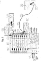
- FIG. 1 shows a module 1 for distributing communications signals in a building or the like.
- the module 1 is connected to respective connectors, 4 and 5, respectively.
- each cable comprises four pairs of twisted wires that are permanently wired to respective ones of eight terminals in connectors 4, 5.
- four of the terminals in the connectors see reference numeral 6, are dedicated to data in and out signals; two terminals, see reference numeral 7, are dedicated to a telephone connection; while two terminals, see reference numeral 8, are dedicated to relatively high-freqency and comparatively weak signals, respectivly, that are used ia to transmit multimedia/image information.
- cable 2 is a short cable
- cable 3 is a long cable.
- the invention presupposes that high-frequency/weak signals are propagated via a twisted pair of wires, about which it is known that the high frequencies are attenuated more than the low frequencies, and that the risk of interferences caused by crosstalk increases with increasing lengths of the cables.
- the invention counters those drawbacks in that filter and.amplifier means are provided, whereby it is possible to individually adjust the output signals from output ports U1-U8 - eg a filter 9 is provided allowing, in the shown embodiment, only signals above 47 MHz to pass from the RF input to amplifiers 10, 11 for adjustment of tilt and gain, respectively, ie frequency characteristics and amplification, before the signal is transmitted further to outputs U1-U8.
- further adjustment means are provided, eg 12 and 13, by means of which it is possible to perform an individual subsequent adjustment of the signal to the various connectors 4, 5.
- the output signal from U1 may typically have an amplitude/frequency characteristic as shown in box 14.
- the amplitude/frequency characteristic of output signals from the connector 4 will be similar to the signal on U1, see box 15. It is a different matter with cable 3 which is a long cable. That cable will impart an attenuation of the signal in response to the frequency and the length of the cable. Therefore, when using means 13 to change the output signal on U6 to have the amplitude/frequency characteristic that appears from box 16 in accordance with the invention, the signal will - when propagated in cable 3 and appearing as output signal from the connector 5 - have the ideal shape that appears from box 17. In this manner it can be accomplished that the signals received in the individual connectors will be the same, no matter where in the building the connector is mounted.
- the module 1 is configured such that there is only one RF input, whereby that signal is transmitted to all connectors, and by a preferred embodiment the twisted pairs of wires that are connected to terminals 8 in the connectors are permanently wired to ports U1-U8. Thereby it is ensured that a user is not able to move the cables around and hence destroy the adjustment made by means of means 12, 13. If for instance the wire 3 is moved from U6 to U3, a new fine adjustment of signals on the outputs is usually to be made.
- module 1 also comprises eight data in/out ports 11-18. Those data signals are transferred in the module (indicated by dotted lines) to respective twisted pairs in cables 2 and 3. Those twisted pairs may be permanently wired in the module 1, in particular if a patch option is available on the input of the module 1 (see Figure 2 and 3 ). Alternatively a patch panel may be provided after the module 1.
- the module 1 comprises connections 18 and 19 for telephone lines.
- switches 20 whereby one may - irrespective of the fact that all twisted pairs in the cable 2 are permanently wired to the module 1 - switch between the one or the other telephone line by means of switches 20.
- FIG. 2 shows a router/switch 27 with connectors 28-31. Those connectors can be connected to respective ones of inputs 11-118 by means of patch cables 32-35. Thus one may decide for oneself which of outputs U1-U8 is connected to router 27.
- an alarm circuit 36 may be connected to a telephone line in such a manner that an alarm, if any, interrupts the usual telephone connection to be able to come through to the connectors.
- Figure 2 also shows that data exchange for the router 27 may occur via a cable-TV modem 37 to-from a data-RF-connection 52 on the module 1.
- a coaxial cable may be connected to the RF-input 38, whereby it is enabled, by one embodiment, to transmit both image information and data information through the coaxial cable.
- the signals are split in the filter 9 as explained in the context of Figure 1 .
- FIG. 3 shows alternative uses of the module 1 according to the invention, where an ADSL modem 39 and an ADSL filter 40 may be connected, thereby also enabling handling of ADSL signals. Moreover a VoIP-converter 41 is shown, whereby it is possible to make telephone conversations over the internet.
- the cables connected to connectors 4, 5 and 21-26 are, in the preferred embodiment, permanently wired to the output of U1-U8, it will appear that the module 1 is very flexible with regard to what else can be transmitted on the four pairs of twisted wires connected to the connectors.
- Figure 4 shows a preferred embodiment for conversion and back-conversion of the sensitive high-frequency and/or weak signals. For the sake of clarity, it is shown in module 1 only what happens in connection with the output U1.
- the amplifier 42 receives an unbalanced signal, typically from a coaxial cable.
- a transformer 43 By means of a transformer 43, whose one winding is connected to earth, a balanced signal is accomplished that is transmitted via a pair of twisted wires, in the figures called pin 7 and 8 (see what was designated by 8 in the context of Figure 1 ).
- pin 7 and 8 see what was designated by 8 in the context of Figure 1 .
- a balanced signal is accomplished in a manner known per se which is less sensitive to noise and crosstalk.
- 44 shows a cable intended for being introduced into one of connectors 4, 5, 21-26.
- the signals are taken out on pins 7 and 8, and by means of a transformer 45 the balanced signal is back-converted to an unbalanced signal on signal output 46.
- this unbalanced signal has a characteristic which remains the same irrespective of the lengths of the cables connecting the module 1 to the cable 44.
- the module 1 contains a sensor 47 which is configured for detecting the presence of a DC signal on the wire 48.
- a sensor 47 which is configured for detecting the presence of a DC signal on the wire 48.
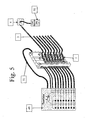
- Figure 5 shows a test box 49 connected to a module 1 and a remote unit 50 connected to a connector 4. It will be understood that the other seven cables from the cable that are dead-ended are connected to respective connectors 5, 21-26, see Figure 2 , and that in each of those connectors a respective remote unit is inserted (which is not shown in Figure 5 ).
- the test box 49 is configured for emitting at least two signals with different frequencies via a coaxial cable 51. The signals are detected in the remote unit 50, where it is checked whether the signal characteristics have the ideal course as outlined in box 17 in Figure 1 .
- the remote unit 50 is configured for transmitting a message back via cable 2 to the test box, whereby it is possible to ascertain, on a display or the diodes indicated on the test box 49 whether there is an ideal adaptation between the module 1 and the connectors 4.
- the remote unit 50 By adjustment by the means 12 from Figure 1 , it is thus possible to quickly adjust the output U1 by means of the test box 49 and the remote unit 50.
- the other outputs U2-U8 are adjusted.
Landscapes
- Engineering & Computer Science (AREA)
- Signal Processing (AREA)
- Computer Networks & Wireless Communication (AREA)
- Multimedia (AREA)
- Automation & Control Theory (AREA)
- Cable Transmission Systems, Equalization Of Radio And Reduction Of Echo (AREA)
- Telephonic Communication Services (AREA)
- Telephone Function (AREA)
- Measuring Pulse, Heart Rate, Blood Pressure Or Blood Flow (AREA)
Abstract
Description
- The invention relates to a module for the distribution of communications signals in a building or the like which is provided with a number of connectors that are connected to the module via a wiring network in the building, said wiring network comprising a cable with a number of pairs of twisted wires.
- In pace with the increasing use of multimedia communication the need increases for buildings being equipped with a wiring network which is able to transmit not only data and telephony signals, but also multimedia signals, ie signals at a significantly higher frequency. Typically telephone signals are between 2 and 8 kHz, data signals are typically as high as 100 kHz, whereas multimedia signals are within the RF area, typically as high as 1000 MHz. The strength of the multimedia signals is moreover significantly lower than the strength of the telephony and data signal strengths, and in order to be able to propagate the signals effectively and without a risk of crosstalk, coaxial cables have so far been used that were dedicated to the multimedia signals. In order to avoid separate wiring networks for the various applications, twisted pairs of cables have gained use also for multimedia signals, which is, however, associated with a number of drawbacks.
- The object of the invention is to provide a module for the distribution of communication signals and multimedia signals that can be distributed simultaneously via a shared wiring network, and wherein the multimedia signal can be transmitted effectively across the distances that are typical for a building. This object is achieved in that the module comprises signal outputs that are connected to respective terminals in some connectors and each of which comprises means for individual adaptation of a respective output signal.
- For instance, by combining these features with an arrangement of the kind known eg from
WO 00/31953 FR2 806 572 A1 - However, the same multimedia signal is often to be emitted to several connectors, and in accordance with a preferred embodiment the signal outputs that have means for individual adaptation are permanently wired to the respective connectors. Thereby the module is ensured against users subsequently disturbing the adaptation. For instance, the arrangement known from
WO 00/31953 - Preferably the individual adaptation comprises an Individual adjustment of the amplifier characteristic of each signal output and preferably also comprises a conversion of the signal from unbalanced to balanced form. In the latter case, a back-conversion is to be performed, which is typically performed in a connecting cable between a connector and a receiver apparatus.
- Compared to the prior art the invention is further suitable for use in connection with the prior art known per se for turning off an output amplifier In case a receiver apparatus is not connected to the connector. This is preferably done by detection of a DC signal level at the respective output on the module.
- Highly advantageously, the module according to the invention can be combined with what is also known from
WO 00/31953 - According to a preferred embodiment a connector comprises eight terminals, two of which are dedicated to analog high-frequency signals, while the other two are dedicated to telephony signals. The remaining four terminals are reserved for digital input and output signals. The digital terminal of each connector is, according to a preferred embodiment, permanently wired to the module which may, in turn, be provided with selector means whereby it is possible to select which digital input and output signals are advanced/returned to the connectors. For instance, according to one embodiment the module may have switches for selection between a number of telephony input signals.
- It applies in general to the invention that data and telephony as well as multimedia signals can be propagated in both directions, whereby everything referred to as input may also serve as output, and vice versa.
- Thus, the invention can also be expressed in the following terms: that it is possible to individually adjust in terms of high-frequency and sensitive signals, while nothing is made in case of rather low-frequency signals. The invention comprises all combinations of patching or switching or a combination of those options before or after the module. Obviously it is possible to construct a large diversified arrangement by means of a number of modules according to the invention.
- In preferred embodiments a high-frequency input/output is connected to a cable-TV modem. By a further embodiment a telephony input/output is connected to an ADSL filter and/or connected to an a-larm unit. The telephone input/output can also be connected to a VolP (Voice over A/P) converter.
- In accordance with the invention, a test box connected to the module and test units connected to respective connectors are also provided. That will make it very simple to perform the individual adaptation. During the test procedure a message is transmitted from each connector about the quality of the received signal. This information can be transmitted wirelessly, but according to a preferred embodiment it may greatly advantageously be transmitted back via the other pairs of twisted wires that are connected to the connector, whereby the individual adjustment can be performed by means of very inexpensive equipment.
- The invention will be explained in further detail by the description of embodiments that follows, reference being made to the drawing, wherein:
-
Figure 1 shows an embodiment of a module according to the invention; -
Figures 2 and3 show various connecting options to the module shown inFigure 1 ; -
Figure 4 shows an embodiment for conversion and back-conversion; while -
Figure 5 shows a test box for use in connection with the invention. -
Figure 1 shows amodule 1 for distributing communications signals in a building or the like. By means ofcables module 1 is connected to respective connectors, 4 and 5, respectively. According to a preferred embodiment each cable comprises four pairs of twisted wires that are permanently wired to respective ones of eight terminals inconnectors reference numeral 7, are dedicated to a telephone connection; while two terminals, see reference numeral 8, are dedicated to relatively high-freqency and comparatively weak signals, respectivly, that are used ia to transmit multimedia/image information. - As outlined in
Figure 1 ,cable 2 is a short cable, whereascable 3 is a long cable. Thus, the invention presupposes that high-frequency/weak signals are propagated via a twisted pair of wires, about which it is known that the high frequencies are attenuated more than the low frequencies, and that the risk of interferences caused by crosstalk increases with increasing lengths of the cables. - The invention counters those drawbacks in that filter and.amplifier means are provided, whereby it is possible to individually adjust the output signals from output ports U1-U8 - eg a filter 9 is provided allowing, in the shown embodiment, only signals above 47 MHz to pass from the RF input to
amplifiers eg various connectors box 14. Owing to the relativelyshort cable 2, the amplitude/frequency characteristic of output signals from theconnector 4 will be similar to the signal on U1, seebox 15. It is a different matter withcable 3 which is a long cable. That cable will impart an attenuation of the signal in response to the frequency and the length of the cable. Therefore, when usingmeans 13 to change the output signal on U6 to have the amplitude/frequency characteristic that appears frombox 16 in accordance with the invention, the signal will - when propagated incable 3 and appearing as output signal from the connector 5 - have the ideal shape that appears frombox 17. In this manner it can be accomplished that the signals received in the individual connectors will be the same, no matter where in the building the connector is mounted. - In principle it is possible to move
cables cable 3 from U6 to eg U3, one may decide which RF input signal is transmitted on to theconnector 5. Preferably themodule 1 is configured such that there is only one RF input, whereby that signal is transmitted to all connectors, and by a preferred embodiment the twisted pairs of wires that are connected to terminals 8 in the connectors are permanently wired to ports U1-U8. Thereby it is ensured that a user is not able to move the cables around and hence destroy the adjustment made by means ofmeans wire 3 is moved from U6 to U3, a new fine adjustment of signals on the outputs is usually to be made. - As will appear from
Figure 1 ,module 1 also comprises eight data in/out ports 11-18. Those data signals are transferred in the module (indicated by dotted lines) to respective twisted pairs incables module 1, in particular if a patch option is available on the input of the module 1 (seeFigure 2 and3 ). Alternatively a patch panel may be provided after themodule 1. - Moreover the
module 1 comprisesconnections switches 20, whereby one may - irrespective of the fact that all twisted pairs in thecable 2 are permanently wired to the module 1 - switch between the one or the other telephone line by means ofswitches 20. - Thus there are ample opportunities for alternating between various data and telephony inputs/outputs, meaning that, by the preferred embodiment, permanently wiring of
cables module 1 will not impose any actual limitations to the flexibility by. By adapting the sensitive signals individually in accordance with the invention, all options are open for a flexible and optimal system. - Reference is now made to
Figure 2 , from where it will appear how each of outputs U1-U8 is connected to arespective connector reference numerals Figure 1 .Figure 2 also shows a router/switch 27 with connectors 28-31. Those connectors can be connected to respective ones of inputs 11-118 by means of patch cables 32-35. Thus one may decide for oneself which of outputs U1-U8 is connected torouter 27. By one embodiment, an alarm circuit 36 may be connected to a telephone line in such a manner that an alarm, if any, interrupts the usual telephone connection to be able to come through to the connectors.Figure 2 also shows that data exchange for therouter 27 may occur via a cable-TV modem 37 to-from a data-RF-connection 52 on themodule 1. Typically a coaxial cable may be connected to the RF-input 38, whereby it is enabled, by one embodiment, to transmit both image information and data information through the coaxial cable. By the preferred embodiment the signals are split in the filter 9 as explained in the context ofFigure 1 . -
Figure 3 shows alternative uses of themodule 1 according to the invention, where anADSL modem 39 and anADSL filter 40 may be connected, thereby also enabling handling of ADSL signals. Moreover a VoIP-converter 41 is shown, whereby it is possible to make telephone conversations over the internet. Albeit the cables connected toconnectors module 1 is very flexible with regard to what else can be transmitted on the four pairs of twisted wires connected to the connectors. -
Figure 4 shows a preferred embodiment for conversion and back-conversion of the sensitive high-frequency and/or weak signals. For the sake of clarity, it is shown inmodule 1 only what happens in connection with the output U1. Theamplifier 42 receives an unbalanced signal, typically from a coaxial cable. By means of atransformer 43, whose one winding is connected to earth, a balanced signal is accomplished that is transmitted via a pair of twisted wires, in the figures calledpin 7 and 8 (see what was designated by 8 in the context ofFigure 1 ). Thereby a balanced signal is accomplished in a manner known per se which is less sensitive to noise and crosstalk. InFigure 4 , 44 shows a cable intended for being introduced into one ofconnectors pins 7 and 8, and by means of atransformer 45 the balanced signal is back-converted to an unbalanced signal onsignal output 46. By means 10, 11 and 12, 13 (Figure 1 ) this unbalanced signal has a characteristic which remains the same irrespective of the lengths of the cables connecting themodule 1 to thecable 44. - Moreover the
module 1 contains asensor 47 which is configured for detecting the presence of a DC signal on thewire 48. By means of a capacitor and a resistor it is ensured that the DC-level is higher than 0 when acable 44 is not coupled to the connector which is connected to U1. The minute one connects acable 44, the DC level onwire 48 will go to zero due to it being connected to a wire in thecable 44 which is, DC-wise, grounded. The minute the DC-level on awire 48 becomes 0, thesensor 47 will emit a signal to apower supply 53 involving activation of theamplifier 42. In this manner it is accomplished that only the sensitive signals are emitted, ie signals with a certain frequency and/or a limited strength when acable 44 is connected. Thereby undesired radiation/noise is reduced and power consumption is minimised. -
Figure 5 shows atest box 49 connected to amodule 1 and aremote unit 50 connected to aconnector 4. It will be understood that the other seven cables from the cable that are dead-ended are connected torespective connectors 5, 21-26, seeFigure 2 , and that in each of those connectors a respective remote unit is inserted (which is not shown inFigure 5 ). Thetest box 49 is configured for emitting at least two signals with different frequencies via acoaxial cable 51. The signals are detected in theremote unit 50, where it is checked whether the signal characteristics have the ideal course as outlined inbox 17 inFigure 1 . Theremote unit 50 is configured for transmitting a message back viacable 2 to the test box, whereby it is possible to ascertain, on a display or the diodes indicated on thetest box 49 whether there is an ideal adaptation between themodule 1 and theconnectors 4. By adjustment by themeans 12 fromFigure 1 , it is thus possible to quickly adjust the output U1 by means of thetest box 49 and theremote unit 50. Correspondingly the other outputs U2-U8 are adjusted.
Claims (18)
- A module (1) for distributing communications signals to a plurality of connectors (4, 5) which are connected to the module (1) via a wiring network, which wiring network comprises a cable (2, 3) with a plurality of pairs of twisted wires, characterised in that the module comprises• two or more output ports (U1, U2) comprising signal outputs that are permanently wired and connected to respective terminals (8) in some connectors (4, 5), and each of which comprises means (12, 13) for individual adaptation of a respective high-frequency input signal to a respective output signal,• said output ports (U1, U6) comprising other signal outputs that are permanently wired to other respective terminals (6, 7) in said connectors (4, 5) for further coupling of one or more other input signals (11-18, 18, 19) to said connectors via the module, wherein the high-frequency input signals have a higher frequency than said other input signals.
- A module according to claim 1, characterised in that the adaptation comprises individual adjustment of the amplification characteristics of each signal output.
- A module according to claims 1 or 2, characterised in that the adaptation comprises conversion from unbalanced to balanced signals.
- A module according to claim 3, characterised in that means are provided between the terminals of the connector and a receiver apparatus for back-conversion of the balanced signals.
- A module according to claim 4, characterised in that the means are integrated into a connecting cable for connection between a connector and a receiver apparatus.
- A module according to claims 1-5, characterised in that at least some of the high-frequency outputs are configured to emit signals only if it can be detected that a receiver is connected to the respective terminals in a connector.
- A module according to claims 4-6, characterised in that the module comprises a detector for detecting a DC signal level and comprises means for turning on or turning off the high-frequency amplifier in response to the magnitude of the DC signal level relative to a threshold value.
- A module according to claim 1, characterised in that the module comprises signal outputs for telephony signals, which outputs are permanently wired to respective terminals in said connectors; and that the module comprises selector means for selection between several telephony input signals.
- A module according to claim 1, characterised in that the module comprises signal outputs for digital signals and comprises selector means for selecting from among several digital input signals.
- A module according to claim 8 or 9, characterised in that the selector means are switches.
- A module according to claim 8 or 9, characterised in that the selector means comprise a patch panel.
- A module according to any one of the preceding claims, characterised in that signal outputs are configured to also serve as signal inputs and vice versa.
- A module according to claims 1-12, characterised in that the module has a high-frequency input/output which is connected to a cable-TV modem.
- A module according to claims 1-13, characterised in that the module has a telephony input/output which is connected to an ADSL filter.
- A module according to claims 1-14, characterised in that the module has a telephone input/output which is connected to an alarm circuit.
- A module according to claims 1-15, characterised in that the module has a telephony input/output connected to a VoIP (Voice over I/P) converter.
- A module according to any one of claims 1-16, characterised in that a test box is available that is connected to the module; and that test units are provided that are connected to respective connectors, wherein the test box is configured for emitting signals with at least two different frequencies; and wherein each test unit is configured for transmitting response back to the test box about the received signals.
- A module according to claim 17, characterised in that the response signals are transmitted from the test units to the test box via said wiring network in the building.
Applications Claiming Priority (2)
| Application Number | Priority Date | Filing Date | Title |
|---|---|---|---|
| DK200501216A DK200501216A (en) | 2005-08-31 | 2005-08-31 | Communication signal distribution module |
| PCT/DK2006/000464 WO2007025542A1 (en) | 2005-08-31 | 2006-08-29 | A module for the distribution of communications signals |
Publications (2)
| Publication Number | Publication Date |
|---|---|
| EP1920559A1 EP1920559A1 (en) | 2008-05-14 |
| EP1920559B1 true EP1920559B1 (en) | 2010-05-19 |
Family
ID=37308855
Family Applications (1)
| Application Number | Title | Priority Date | Filing Date |
|---|---|---|---|
| EP06775951A Active EP1920559B1 (en) | 2005-08-31 | 2006-08-29 | A module for the distribution of communications signals |
Country Status (9)
| Country | Link |
|---|---|
| EP (1) | EP1920559B1 (en) |
| CN (1) | CN101300783A (en) |
| AT (1) | ATE468682T1 (en) |
| AU (1) | AU2006286933A1 (en) |
| DE (1) | DE602006014419D1 (en) |
| DK (1) | DK200501216A (en) |
| NO (1) | NO20081499L (en) |
| RU (1) | RU2008110401A (en) |
| WO (1) | WO2007025542A1 (en) |
Families Citing this family (1)
| Publication number | Priority date | Publication date | Assignee | Title |
|---|---|---|---|---|
| FR2987536B1 (en) * | 2012-02-27 | 2015-02-20 | Schneider Electric Ind Sas | MULTIMEDIA BREWING SYSTEM |
Family Cites Families (12)
| Publication number | Priority date | Publication date | Assignee | Title |
|---|---|---|---|---|
| FR2634608B1 (en) * | 1988-07-22 | 1994-05-06 | Etat Francais Cnet | RECONFIGURABLE MULTI-POINT CABLE DOMOTIC NETWORK FOR SIMULTANEOUS AND / OR ALTERNATIVE DISTRIBUTION OF MULTIPLE SIGNAL TYPES, ESPECIALLY BASIC BAND IMAGE SIGNALS, AND METHOD FOR CONFIGURING SUCH A NETWORK |
| US6160843A (en) * | 1996-03-29 | 2000-12-12 | Cisco Technology, Inc. | Communication server apparatus providing XDSL services and method |
| US6072793A (en) * | 1997-06-12 | 2000-06-06 | Lucent Technologies Inc. | Electronically controlled main distributing frame |
| US6537106B1 (en) * | 1998-06-05 | 2003-03-25 | Adc Telecommunications, Inc. | Telecommunications patch panel with angled connector modules |
| PL197950B1 (en) | 1998-11-20 | 2008-05-30 | Schneider Electric Danmark As | A method for the distribution and transfer of communication and multimedia signals, as well as a signal distribution arrangement for the transfer of the communication and multimedia signals |
| ATE264035T1 (en) * | 1999-06-11 | 2004-04-15 | Daetwyler Ag Kabel & Systeme | SYSTEM FOR THE UNIVERSAL CABLING OF A BUILDING OR SEVERAL USERS, COMPONENTS OF SUCH A SYSTEM AND ASSOCIATED METHOD |
| FR2806572B1 (en) * | 2000-03-16 | 2005-02-04 | Micsystemes Sa | MULTIMEDIA SYSTEM AND METHOD FOR DISTRIBUTING WIRELESS AND CABLE CHAINS IN A CABLE NETWORK IN TORSADE PAIRS |
| SE0004037D0 (en) * | 2000-11-03 | 2000-11-03 | Ericsson Telefon Ab L M | Apparatus and method for provision of broadband access in a telecommunication system |
| GB2378874A (en) * | 2001-04-30 | 2003-02-19 | Frank Ainscow | Audiovisual distribution system |
| FR2830156B1 (en) * | 2001-09-25 | 2004-11-26 | Henri Lee | TV DISTRIBUTION SYSTEM AND PROCESSING UNIT USED IN THIS DISTRIBUTION SYSTEM |
| US6738353B2 (en) * | 2002-03-20 | 2004-05-18 | Sunrise Telecom Incorporated | System and method for monitoring a packet network |
| EP1627451A2 (en) * | 2003-05-23 | 2006-02-22 | Tyco Electronics AMP Espana S.A. | Communications interface |
-
2005
- 2005-08-31 DK DK200501216A patent/DK200501216A/en not_active Application Discontinuation
-
2006
- 2006-08-29 AT AT06775951T patent/ATE468682T1/en not_active IP Right Cessation
- 2006-08-29 RU RU2008110401/09A patent/RU2008110401A/en not_active Application Discontinuation
- 2006-08-29 AU AU2006286933A patent/AU2006286933A1/en not_active Abandoned
- 2006-08-29 WO PCT/DK2006/000464 patent/WO2007025542A1/en not_active Ceased
- 2006-08-29 EP EP06775951A patent/EP1920559B1/en active Active
- 2006-08-29 DE DE602006014419T patent/DE602006014419D1/en active Active
- 2006-08-29 CN CNA2006800391723A patent/CN101300783A/en active Pending
-
2008
- 2008-03-27 NO NO20081499A patent/NO20081499L/en not_active Application Discontinuation
Also Published As
| Publication number | Publication date |
|---|---|
| EP1920559A1 (en) | 2008-05-14 |
| WO2007025542A1 (en) | 2007-03-08 |
| DE602006014419D1 (en) | 2010-07-01 |
| DK200501216A (en) | 2007-03-01 |
| AU2006286933A1 (en) | 2007-03-08 |
| RU2008110401A (en) | 2009-10-10 |
| ATE468682T1 (en) | 2010-06-15 |
| CN101300783A (en) | 2008-11-05 |
| NO20081499L (en) | 2008-04-29 |
Similar Documents
| Publication | Publication Date | Title |
|---|---|---|
| US8982903B2 (en) | Network combining wired and non-wired segments | |
| US6532279B1 (en) | High-speed data communication over a residential telephone wiring network | |
| EP2548340B1 (en) | Switchable wired-wireless electromagnetic signal communication | |
| US20070047712A1 (en) | Scalable, distributed architecture for fully connected network intercom system | |
| JP2002509668A (en) | Twisted pair communication system | |
| AU5540799A (en) | Method and apparatus for data communication | |
| US6195004B1 (en) | Distributed earcon local area network | |
| WO2012081707A1 (en) | Communication system and intercom system for multiple-family dwelling | |
| US7816803B1 (en) | Power line control system | |
| EP1920559A1 (en) | A module for the distribution of communications signals | |
| US12335065B2 (en) | Devices, systems and methods for transmitting data compliant with home networking standard over twisted pair cables | |
| CN104869518A (en) | Wall-mounted loud-speaking talkback terminal and loud-speaking talkback system | |
| CA2579723C (en) | Telephone line interface, side-tone attenuation circuit and method | |
| MXPA99011003A (en) | Twisted pair communication system. | |
| CN106416212A (en) | Communications network | |
| JP2013046262A (en) | Communication device, communication method, communication program and communication system | |
| JPH04252528A (en) | Optical matching adaptor | |
| JP2007166111A (en) | Brancher for transmission system and transmission system | |
| JP2007074236A (en) | COMMUNICATION DEVICE WITH INTEGRATED FUNCTION, INTERMEDIATE COUPLER, TERMINAL COMMUNICATION DEVICE AND WIRING FORM | |
| JPWO2004004299A1 (en) | xDSL relay device and communication system | |
| JP2008048049A (en) | Intercom system for multiple dwelling house | |
| HK1177557B (en) | Switchable wired-wireless electromagnetic signal communication | |
| HK1177994A (en) | Outlet with analog signal adapter | |
| JPS62289043A (en) | Mutual simultaneous communication equipment by voice multiplex system |
Legal Events
| Date | Code | Title | Description |
|---|---|---|---|
| PUAI | Public reference made under article 153(3) epc to a published international application that has entered the european phase |
Free format text: ORIGINAL CODE: 0009012 |
|
| 17P | Request for examination filed |
Effective date: 20080225 |
|
| AK | Designated contracting states |
Kind code of ref document: A1 Designated state(s): AT BE BG CH CY CZ DE DK EE ES FI FR GB GR HU IE IS IT LI LT LU LV MC NL PL PT RO SE SI SK TR |
|
| 17Q | First examination report despatched |
Effective date: 20080616 |
|
| GRAP | Despatch of communication of intention to grant a patent |
Free format text: ORIGINAL CODE: EPIDOSNIGR1 |
|
| GRAS | Grant fee paid |
Free format text: ORIGINAL CODE: EPIDOSNIGR3 |
|
| GRAA | (expected) grant |
Free format text: ORIGINAL CODE: 0009210 |
|
| AK | Designated contracting states |
Kind code of ref document: B1 Designated state(s): AT BE BG CH CY CZ DE DK EE ES FI FR GB GR HU IE IS IT LI LT LU LV MC NL PL PT RO SE SI SK TR |
|
| REG | Reference to a national code |
Ref country code: GB Ref legal event code: FG4D |
|
| REG | Reference to a national code |
Ref country code: CH Ref legal event code: EP |
|
| REG | Reference to a national code |
Ref country code: IE Ref legal event code: FG4D |
|
| REF | Corresponds to: |
Ref document number: 602006014419 Country of ref document: DE Date of ref document: 20100701 Kind code of ref document: P |
|
| REG | Reference to a national code |
Ref country code: NL Ref legal event code: VDEP Effective date: 20100519 |
|
| LTIE | Lt: invalidation of european patent or patent extension |
Effective date: 20100519 |
|
| PG25 | Lapsed in a contracting state [announced via postgrant information from national office to epo] |
Ref country code: SE Free format text: LAPSE BECAUSE OF FAILURE TO SUBMIT A TRANSLATION OF THE DESCRIPTION OR TO PAY THE FEE WITHIN THE PRESCRIBED TIME-LIMIT Effective date: 20100519 Ref country code: LT Free format text: LAPSE BECAUSE OF FAILURE TO SUBMIT A TRANSLATION OF THE DESCRIPTION OR TO PAY THE FEE WITHIN THE PRESCRIBED TIME-LIMIT Effective date: 20100519 Ref country code: ES Free format text: LAPSE BECAUSE OF FAILURE TO SUBMIT A TRANSLATION OF THE DESCRIPTION OR TO PAY THE FEE WITHIN THE PRESCRIBED TIME-LIMIT Effective date: 20100830 |
|
| PG25 | Lapsed in a contracting state [announced via postgrant information from national office to epo] |
Ref country code: FI Free format text: LAPSE BECAUSE OF FAILURE TO SUBMIT A TRANSLATION OF THE DESCRIPTION OR TO PAY THE FEE WITHIN THE PRESCRIBED TIME-LIMIT Effective date: 20100519 Ref country code: IS Free format text: LAPSE BECAUSE OF FAILURE TO SUBMIT A TRANSLATION OF THE DESCRIPTION OR TO PAY THE FEE WITHIN THE PRESCRIBED TIME-LIMIT Effective date: 20100919 Ref country code: LV Free format text: LAPSE BECAUSE OF FAILURE TO SUBMIT A TRANSLATION OF THE DESCRIPTION OR TO PAY THE FEE WITHIN THE PRESCRIBED TIME-LIMIT Effective date: 20100519 Ref country code: SI Free format text: LAPSE BECAUSE OF FAILURE TO SUBMIT A TRANSLATION OF THE DESCRIPTION OR TO PAY THE FEE WITHIN THE PRESCRIBED TIME-LIMIT Effective date: 20100519 Ref country code: AT Free format text: LAPSE BECAUSE OF FAILURE TO SUBMIT A TRANSLATION OF THE DESCRIPTION OR TO PAY THE FEE WITHIN THE PRESCRIBED TIME-LIMIT Effective date: 20100519 |
|
| PG25 | Lapsed in a contracting state [announced via postgrant information from national office to epo] |
Ref country code: PL Free format text: LAPSE BECAUSE OF FAILURE TO SUBMIT A TRANSLATION OF THE DESCRIPTION OR TO PAY THE FEE WITHIN THE PRESCRIBED TIME-LIMIT Effective date: 20100519 Ref country code: GR Free format text: LAPSE BECAUSE OF FAILURE TO SUBMIT A TRANSLATION OF THE DESCRIPTION OR TO PAY THE FEE WITHIN THE PRESCRIBED TIME-LIMIT Effective date: 20100820 Ref country code: CY Free format text: LAPSE BECAUSE OF FAILURE TO SUBMIT A TRANSLATION OF THE DESCRIPTION OR TO PAY THE FEE WITHIN THE PRESCRIBED TIME-LIMIT Effective date: 20100526 |
|
| PG25 | Lapsed in a contracting state [announced via postgrant information from national office to epo] |
Ref country code: DK Free format text: LAPSE BECAUSE OF FAILURE TO SUBMIT A TRANSLATION OF THE DESCRIPTION OR TO PAY THE FEE WITHIN THE PRESCRIBED TIME-LIMIT Effective date: 20100519 Ref country code: PT Free format text: LAPSE BECAUSE OF FAILURE TO SUBMIT A TRANSLATION OF THE DESCRIPTION OR TO PAY THE FEE WITHIN THE PRESCRIBED TIME-LIMIT Effective date: 20100920 Ref country code: NL Free format text: LAPSE BECAUSE OF FAILURE TO SUBMIT A TRANSLATION OF THE DESCRIPTION OR TO PAY THE FEE WITHIN THE PRESCRIBED TIME-LIMIT Effective date: 20100519 Ref country code: EE Free format text: LAPSE BECAUSE OF FAILURE TO SUBMIT A TRANSLATION OF THE DESCRIPTION OR TO PAY THE FEE WITHIN THE PRESCRIBED TIME-LIMIT Effective date: 20100519 |
|
| PG25 | Lapsed in a contracting state [announced via postgrant information from national office to epo] |
Ref country code: CZ Free format text: LAPSE BECAUSE OF FAILURE TO SUBMIT A TRANSLATION OF THE DESCRIPTION OR TO PAY THE FEE WITHIN THE PRESCRIBED TIME-LIMIT Effective date: 20100519 Ref country code: SK Free format text: LAPSE BECAUSE OF FAILURE TO SUBMIT A TRANSLATION OF THE DESCRIPTION OR TO PAY THE FEE WITHIN THE PRESCRIBED TIME-LIMIT Effective date: 20100519 Ref country code: RO Free format text: LAPSE BECAUSE OF FAILURE TO SUBMIT A TRANSLATION OF THE DESCRIPTION OR TO PAY THE FEE WITHIN THE PRESCRIBED TIME-LIMIT Effective date: 20100519 Ref country code: BE Free format text: LAPSE BECAUSE OF FAILURE TO SUBMIT A TRANSLATION OF THE DESCRIPTION OR TO PAY THE FEE WITHIN THE PRESCRIBED TIME-LIMIT Effective date: 20100519 |
|
| PLBE | No opposition filed within time limit |
Free format text: ORIGINAL CODE: 0009261 |
|
| STAA | Information on the status of an ep patent application or granted ep patent |
Free format text: STATUS: NO OPPOSITION FILED WITHIN TIME LIMIT |
|
| PG25 | Lapsed in a contracting state [announced via postgrant information from national office to epo] |
Ref country code: IT Free format text: LAPSE BECAUSE OF FAILURE TO SUBMIT A TRANSLATION OF THE DESCRIPTION OR TO PAY THE FEE WITHIN THE PRESCRIBED TIME-LIMIT Effective date: 20100519 Ref country code: MC Free format text: LAPSE BECAUSE OF NON-PAYMENT OF DUE FEES Effective date: 20100831 |
|
| REG | Reference to a national code |
Ref country code: CH Ref legal event code: PL |
|
| 26N | No opposition filed |
Effective date: 20110222 |
|
| GBPC | Gb: european patent ceased through non-payment of renewal fee |
Effective date: 20100829 |
|
| PG25 | Lapsed in a contracting state [announced via postgrant information from national office to epo] |
Ref country code: LI Free format text: LAPSE BECAUSE OF NON-PAYMENT OF DUE FEES Effective date: 20100831 Ref country code: CH Free format text: LAPSE BECAUSE OF NON-PAYMENT OF DUE FEES Effective date: 20100831 |
|
| REG | Reference to a national code |
Ref country code: DE Ref legal event code: R097 Ref document number: 602006014419 Country of ref document: DE Effective date: 20110221 |
|
| REG | Reference to a national code |
Ref country code: DE Ref legal event code: R119 Ref document number: 602006014419 Country of ref document: DE Effective date: 20110301 |
|
| PG25 | Lapsed in a contracting state [announced via postgrant information from national office to epo] |
Ref country code: DE Free format text: LAPSE BECAUSE OF NON-PAYMENT OF DUE FEES Effective date: 20110301 Ref country code: IE Free format text: LAPSE BECAUSE OF NON-PAYMENT OF DUE FEES Effective date: 20100829 |
|
| PG25 | Lapsed in a contracting state [announced via postgrant information from national office to epo] |
Ref country code: GB Free format text: LAPSE BECAUSE OF NON-PAYMENT OF DUE FEES Effective date: 20100829 |
|
| PG25 | Lapsed in a contracting state [announced via postgrant information from national office to epo] |
Ref country code: BG Free format text: LAPSE BECAUSE OF FAILURE TO SUBMIT A TRANSLATION OF THE DESCRIPTION OR TO PAY THE FEE WITHIN THE PRESCRIBED TIME-LIMIT Effective date: 20100519 Ref country code: LU Free format text: LAPSE BECAUSE OF NON-PAYMENT OF DUE FEES Effective date: 20100829 Ref country code: HU Free format text: LAPSE BECAUSE OF FAILURE TO SUBMIT A TRANSLATION OF THE DESCRIPTION OR TO PAY THE FEE WITHIN THE PRESCRIBED TIME-LIMIT Effective date: 20101120 |
|
| PG25 | Lapsed in a contracting state [announced via postgrant information from national office to epo] |
Ref country code: TR Free format text: LAPSE BECAUSE OF FAILURE TO SUBMIT A TRANSLATION OF THE DESCRIPTION OR TO PAY THE FEE WITHIN THE PRESCRIBED TIME-LIMIT Effective date: 20100519 |
|
| PG25 | Lapsed in a contracting state [announced via postgrant information from national office to epo] |
Ref country code: BG Free format text: LAPSE BECAUSE OF FAILURE TO SUBMIT A TRANSLATION OF THE DESCRIPTION OR TO PAY THE FEE WITHIN THE PRESCRIBED TIME-LIMIT Effective date: 20100819 |
|
| REG | Reference to a national code |
Ref country code: FR Ref legal event code: PLFP Year of fee payment: 10 |
|
| REG | Reference to a national code |
Ref country code: FR Ref legal event code: PLFP Year of fee payment: 11 |
|
| REG | Reference to a national code |
Ref country code: FR Ref legal event code: PLFP Year of fee payment: 12 |
|
| REG | Reference to a national code |
Ref country code: FR Ref legal event code: PLFP Year of fee payment: 13 |
|
| PGFP | Annual fee paid to national office [announced via postgrant information from national office to epo] |
Ref country code: FR Payment date: 20250703 Year of fee payment: 20 |