EP1919777B1 - A method and an apparatus for sterilising packages - Google Patents
A method and an apparatus for sterilising packages Download PDFInfo
- Publication number
- EP1919777B1 EP1919777B1 EP06758056.3A EP06758056A EP1919777B1 EP 1919777 B1 EP1919777 B1 EP 1919777B1 EP 06758056 A EP06758056 A EP 06758056A EP 1919777 B1 EP1919777 B1 EP 1919777B1
- Authority
- EP
- European Patent Office
- Prior art keywords
- package
- flow
- gas
- angled
- supplied
- Prior art date
- Legal status (The legal status is an assumption and is not a legal conclusion. Google has not performed a legal analysis and makes no representation as to the accuracy of the status listed.)
- Not-in-force
Links
Images

Classifications
-
- B—PERFORMING OPERATIONS; TRANSPORTING
- B65—CONVEYING; PACKING; STORING; HANDLING THIN OR FILAMENTARY MATERIAL
- B65B—MACHINES, APPARATUS OR DEVICES FOR, OR METHODS OF, PACKAGING ARTICLES OR MATERIALS; UNPACKING
- B65B39/00—Nozzles, funnels or guides for introducing articles or materials into containers or wrappers
- B65B39/04—Nozzles, funnels or guides for introducing articles or materials into containers or wrappers having air-escape, or air-withdrawal, passages
-
- A—HUMAN NECESSITIES
- A61—MEDICAL OR VETERINARY SCIENCE; HYGIENE
- A61L—METHODS OR APPARATUS FOR STERILISING MATERIALS OR OBJECTS IN GENERAL; DISINFECTION, STERILISATION OR DEODORISATION OF AIR; CHEMICAL ASPECTS OF BANDAGES, DRESSINGS, ABSORBENT PADS OR SURGICAL ARTICLES; MATERIALS FOR BANDAGES, DRESSINGS, ABSORBENT PADS OR SURGICAL ARTICLES
- A61L2/00—Disinfection or sterilisation of materials or objects, in general; Accessories therefor
- A61L2/16—Disinfection or sterilisation of materials or objects, in general; Accessories therefor using chemical substances
- A61L2/20—Gaseous substances, e.g. vapours
-
- B—PERFORMING OPERATIONS; TRANSPORTING
- B65—CONVEYING; PACKING; STORING; HANDLING THIN OR FILAMENTARY MATERIAL
- B65B—MACHINES, APPARATUS OR DEVICES FOR, OR METHODS OF, PACKAGING ARTICLES OR MATERIALS; UNPACKING
- B65B55/00—Preserving, protecting or purifying packages or package contents in association with packaging
- B65B55/02—Sterilising, e.g. of complete packages
- B65B55/04—Sterilising wrappers or receptacles prior to, or during, packaging
- B65B55/10—Sterilising wrappers or receptacles prior to, or during, packaging by liquids or gases
-
- A—HUMAN NECESSITIES
- A61—MEDICAL OR VETERINARY SCIENCE; HYGIENE
- A61L—METHODS OR APPARATUS FOR STERILISING MATERIALS OR OBJECTS IN GENERAL; DISINFECTION, STERILISATION OR DEODORISATION OF AIR; CHEMICAL ASPECTS OF BANDAGES, DRESSINGS, ABSORBENT PADS OR SURGICAL ARTICLES; MATERIALS FOR BANDAGES, DRESSINGS, ABSORBENT PADS OR SURGICAL ARTICLES
- A61L2202/00—Aspects relating to methods or apparatus for disinfecting or sterilising materials or objects
- A61L2202/10—Apparatus features
- A61L2202/15—Biocide distribution means, e.g. nozzles, pumps, manifolds, fans, baffles, sprayers
-
- B—PERFORMING OPERATIONS; TRANSPORTING
- B65—CONVEYING; PACKING; STORING; HANDLING THIN OR FILAMENTARY MATERIAL
- B65B—MACHINES, APPARATUS OR DEVICES FOR, OR METHODS OF, PACKAGING ARTICLES OR MATERIALS; UNPACKING
- B65B39/00—Nozzles, funnels or guides for introducing articles or materials into containers or wrappers
- B65B2039/009—Multiple outlets
-
- B—PERFORMING OPERATIONS; TRANSPORTING
- B65—CONVEYING; PACKING; STORING; HANDLING THIN OR FILAMENTARY MATERIAL
- B65B—MACHINES, APPARATUS OR DEVICES FOR, OR METHODS OF, PACKAGING ARTICLES OR MATERIALS; UNPACKING
- B65B2210/00—Specific aspects of the packaging machine
- B65B2210/06—Sterilising or cleaning machinery or conduits
Definitions
- the present invention relates to a method and an apparatus for sterilising at least partly formed packages which are ready-to-fill packages, in a filling machine.
- sterile is taken to signify in the following disclosure that the package, after sterilisation, attains a level of sterilisation which is designated commercially sterile.
- the present invention relates to a method, prior to filling of such packages, of treating and sterilising them in a filling machine before a subsequent aseptic filling.
- the packages have an open and a closed end.
- a first context in which the method according to the present invention may be implemented is in connection with the introductory supply, before filling of such packages, of hot air from the open end of the packages in order to heat them up with a view, in a later sterilisation stage, to preventing sterilisation gas from condensing on the walls of the packages.
- Another manner of implementing the method is to supply sterile tempered air once the package has been gassed with sterilisation gas. The purpose here is to ventilate off the sterilisation gas.
- the present invention relates to a method of supplying and removing an optional gas, hence also sterilisation gas to and from the open end of the package.
- the present invention further relates to an apparatus which is included in a larger context for realising a gas sterilisation of packages in said filling machine
- the larger context includes, on the one hand, a heating zone, and on the other hand a sterilisation zone or a combination thereof and further a ventilation zone.
- the sterilisation agent is intended to remain in gas form throughout the entire sterilisation stage and is intended to the greatest possible degree to be reused.
- DE-A-3339930 relates to a gas supplying apparatus in a filling machine of the generic kind, wherein the gas is supplied by means of a ring-shaped nozzle such that the gas flow is directed vertically downwards along the inner side wall of a cup-shaped package.
- One object of the present invention is to disclose a method, with the best conceivable overriding control prior to filling of a ready-to-fill package under aseptic conditions, to carry out a gas sterilisation process of the inside of said package to the preselected level of sterilisation, with a considerably lower gas mass flow of the supplied gases or gas mixtures as compared with the prior art.
- one object of the present invention is to disclose a method which, in particular in the specifically disclosed case, obviates the risk that the sterilisation will be incomplete, at the same time as the mass flow of the supplied gases is greatly reduced compared with the prior art.
- Yet a further object of the present invention is to realise a method which makes for a considerably higher level of reusing of the supplied sterilisation gas.
- Yet a further object of the present invention is to disclose an apparatus for, on the one hand, realising a reduction of the risk of re-infection or contamination with a view to better being able to guarantee the shelf-life of the product which is subsequently filled into the package, and, on the other hand, for realising a reduction of the gas mass flow in connection with the sterilisation and thereby improve the economy of the process, whereby considerably improved possibilities will occur for reusing, in particular concerning the supplied sterilisation gas.
- the unintentional spreading of the sterilisation gas in the aseptic chamber can be restricted to an even higher degree than before.
- Said chamber consists, on the one hand, of a unit for the supply of hot air, and, on the other hand, of a unit for the supply and removal of sterilisation agent, and also a unit for ventilation of packages of sterilisation gas before they are filled.
- an apparatus in a filling machine a method of supplying a gas air gas mixture to the inside of partly formed packages whjch are ready-to-fill, before subsequent filling and sealing of the packages.
- the gas or gas mixture supplied at any given moment is supplied as a flow which is radially inwardly defined in relation to the inner wall of the package, such that the flow is angled with respect to the geometric major longitudinal axis (H) of the package which intersects its opening so that the flow, since it is defined by the inner wall of the package, is controlled for the formation of a helical flow vortex.
- the apparatus includes a nozzle for the flow of gas or gas mixture which includes at least one channel for the gas or gas mixture which is angled in relation to at least one plane containing that one of the geometric major axes of the package which intersects the opening of the package at a right angle such that the flow therefrom, when it impinges on the inner wall of the package, develops a both radially inwardly defined flow while forming a helical flow vortex.
- the supply means should encompass some ten-odd apertures, where each one of them moreover advantageously should be angled in such a manner that it makes an angle of less than 8° to each one of the two planes of symmetry to the package which have the axis of symmetry intersecting the opening under a right angle as a common line.
- each aperture is directed in a first direction slightly peripherally and in a second direction slightly towards the centre of the package.
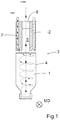
- FIG. 1 shows the fundamental function of the invention.
- a package 1 in a sequence of identical packages and with, in this case, an open bottom runs along a belt for the progressive indexing of, for example, four packages 1 at a time in the machine direction MD.
- Those stages through which the package at least thereby substantially passes are one for heating the package to about 70°C, one for sterilising the package with gaseous hydrogen peroxide or other sterilisation gas, and one for ventilation thereof with sterile air.
- these stages need not be wholly single action stages but, if desired, may be "phased" in the sense that, for example, the heating stage may progressively be mixed with the sterilisation stage in an increasing degree in the machine direction so that the number of sterilisation gas apertures increases progressively.
- the heating stage may progressively be mixed with the sterilisation stage in an increasing degree in the machine direction so that the number of sterilisation gas apertures increases progressively.
- each respective package 1 Regardless of whether it is hot air, sterilisation gas or sterile ventilation air which is supplied in the channels 2 illustrated in Fig. 1 in an apparatus 3 according to the invention, it may be ascertained that the flow which results in that the channels 2 are, in their lower ends, angled in such a manner that they make an angle of less than or equal to 8° to both of the planes of symmetry which display the symmetry axis H which intersects the opening of the package at a right angle as a common line, hence angled in a first direction somewhat peripherally and in a second direction slightly towards the centre of the package imparts the best conceivable vortex helical form to the gas flow angled down in the package on its way down.
- the apparatus includes ten channels 2 uniformly distributed along the upper region of the described apparatus 3. It is once again worthy of pointing out that the experiments which have been carried out with water as a medium have demonstrated that the medium which is fed via the channels 2 with this configuration will flow out of the package as a substantially central flow upwards in the package 1 in order, at its upper region 4, to be able to flow into a central return channel 5. As is intimated by broken lines in the upper part of the figure, the channel 5 may discharge straight up at reference numeral 6. The desired effect will thereby be attained depending upon the quantity of supplied gas, either as improved heating, improved sterilisation or improved ventilation.
- Fig. 2 shows a gassing assembly 8 comprising an apparatus 3 according to the invention in an integrated composite state with the assembly 8.
- the assembly 8 has an inlet chamber 9 with a central gas inlet connection 10 and a plate 11 for fixing of the assembly to a filling machine (not shown).
- Fig. 3 is a perspective exploded view of the assembly 8.
- the apparatus 3 is also shown here in perspective, for which reason its various component parts, above all the channels 2 are clearly apparent.
- the fact that the channels 2 are ten in number is, as was mentioned above, a coincidence, since the number depends upon the circumference.
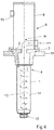
- Fig. 4 shows the assembly 8 as a central cross section in a position corresponding to that which the assembly 8 will have when it is run in production.
- this figure shows an imaginary flow pattern corresponding to that which is illustrated in the fundamental outline drawing in Fig. 1 .
- the return flow also takes place out of the package of the supplied gas in a controlled manner.
- the return flow reaches the bottom opening of the package 1, this is taken care of in the return channel 5, in whose upper region this is deflected approx. 180° in order to be led out via the outer periphery of the package.
- the present invention makes for a considerable reduction of the mass flow, whereby this flow no longer constitutes a potential risk for turbulent currents occurring in the interface region beside and beneath the package.
Landscapes
- Mechanical Engineering (AREA)
- Engineering & Computer Science (AREA)
- Health & Medical Sciences (AREA)
- Animal Behavior & Ethology (AREA)
- General Chemical & Material Sciences (AREA)
- Chemical Kinetics & Catalysis (AREA)
- Epidemiology (AREA)
- Life Sciences & Earth Sciences (AREA)
- Chemical & Material Sciences (AREA)
- General Health & Medical Sciences (AREA)
- Public Health (AREA)
- Veterinary Medicine (AREA)
- Apparatus For Disinfection Or Sterilisation (AREA)
- Vacuum Packaging (AREA)
- Food Preservation Except Freezing, Refrigeration, And Drying (AREA)
- Basic Packing Technique (AREA)
Description
- The present invention relates to a method and an apparatus for sterilising at least partly formed packages which are ready-to-fill packages, in a filling machine. The term sterile is taken to signify in the following disclosure that the package, after sterilisation, attains a level of sterilisation which is designated commercially sterile.
- More precisely, the present invention relates to a method, prior to filling of such packages, of treating and sterilising them in a filling machine before a subsequent aseptic filling. The packages have an open and a closed end. A first context in which the method according to the present invention may be implemented is in connection with the introductory supply, before filling of such packages, of hot air from the open end of the packages in order to heat them up with a view, in a later sterilisation stage, to preventing sterilisation gas from condensing on the walls of the packages. Another manner of implementing the method is to supply sterile tempered air once the package has been gassed with sterilisation gas. The purpose here is to ventilate off the sterilisation gas. More specifically, the present invention relates to a method of supplying and removing an optional gas, hence also sterilisation gas to and from the open end of the package.
- The present invention further relates to an apparatus which is included in a larger context for realising a gas sterilisation of packages in said filling machine where the larger context includes, on the one hand, a heating zone, and on the other hand a sterilisation zone or a combination thereof and further a ventilation zone. The sterilisation agent is intended to remain in gas form throughout the entire sterilisation stage and is intended to the greatest possible degree to be reused. For a more detailed description of one type of an apparatus and a method for producing and sterilising a package which is referable to this group, reference is made to published international application
WO2004/054883 . - In filling machines of said type, use has previously been made of a method of approach which entails that, during the gas sterilisation stage, a sterilisation gas is supplied centrally in conjunction with the open end of each package. For reasons of process engineering, the sterilisation gas flow has been allowed to remain constant, regardless of the necessary movements in the filling machine. This is linked to the situation that the relevant technology is applicable in connection with filling machines of different types, such as also those of the tube filling- or carousel filling type. It has proved that, in certain cases, there may be a minor risk that the sterilisation gas which, in a previously known manner, is supplied to packages of this type in some cases does not reach the small areas and pockets of the package which are located least readily accessible in relation to the sterilisation agent supplying device. This applies particularly to such packages which display a relatively large ratio between their length and their main axis cross section. It has long been assumed that it is possible to reach these small areas and pockets of the packages located least readily accessible by maintaining a high constant gas mass flow in the supplied sterilisation gas. However, it has now been established that, above all in certain cases, there is a risk that the preselected level of sterilisation will not be achieved simply by this measure.
DE-A-3339930 relates to a gas supplying apparatus in a filling machine of the generic kind, wherein the gas is supplied by means of a ring-shaped nozzle such that the gas flow is directed vertically downwards along the inner side wall of a cup-shaped package. - One object of the present invention is to disclose a method, with the best conceivable overriding control prior to filling of a ready-to-fill package under aseptic conditions, to carry out a gas sterilisation process of the inside of said package to the preselected level of sterilisation, with a considerably lower gas mass flow of the supplied gases or gas mixtures as compared with the prior art.
- More specifically, one object of the present invention is to disclose a method which, in particular in the specifically disclosed case, obviates the risk that the sterilisation will be incomplete, at the same time as the mass flow of the supplied gases is greatly reduced compared with the prior art.
- Yet a further object of the present invention is to realise a method which makes for a considerably higher level of reusing of the supplied sterilisation gas.
- Yet a further object of the present invention is to disclose an apparatus for, on the one hand, realising a reduction of the risk of re-infection or contamination with a view to better being able to guarantee the shelf-life of the product which is subsequently filled into the package, and, on the other hand, for realising a reduction of the gas mass flow in connection with the sterilisation and thereby improve the economy of the process, whereby considerably improved possibilities will occur for reusing, in particular concerning the supplied sterilisation gas. As a result, the unintentional spreading of the sterilisation gas in the aseptic chamber can be restricted to an even higher degree than before. Said chamber consists, on the one hand, of a unit for the supply of hot air, and, on the other hand, of a unit for the supply and removal of sterilisation agent, and also a unit for ventilation of packages of sterilisation gas before they are filled.
- According to the present invention, there is provided in an apparatus in a filling machine a method of supplying a gas air gas mixture to the inside of partly formed packages whjch are ready-to-fill, before subsequent filling and sealing of the packages. The gas or gas mixture supplied at any given moment is supplied as a flow which is radially inwardly defined in relation to the inner wall of the package, such that the flow is angled with respect to the geometric major longitudinal axis (H) of the package which intersects its opening so that the flow, since it is defined by the inner wall of the package, is controlled for the formation of a helical flow vortex. The thus created flow vortex forms, as a consequence that it must, by some means, find a way out again, a central return flow thanks to a lower gas pressure in this central region. Hereby, the gas velocity may, regardless of the gas type which is employed, be reduced. One advantage inherent herein is that it is thereby possible to eliminate positive flow vortices in the treatment chamber. Furthermore, there will be provided according to the invention an apparatus in a filling machine for supplying gas or gas mixtures to the inside of packages before a subsequent filling and sealing of the packages., The apparatus includes a nozzle for the flow of gas or gas mixture which includes at least one channel for the gas or gas mixture which is angled in relation to at least one plane containing that one of the geometric major axes of the package which intersects the opening of the package at a right angle such that the flow therefrom, when it impinges on the inner wall of the package, develops a both radially inwardly defined flow while forming a helical flow vortex. In order to attain the best possible flow distribution when gas is supplied, it has proved in trials hitherto that the supply means should encompass some ten-odd apertures, where each one of them moreover advantageously should be angled in such a manner that it makes an angle of less than 8° to each one of the two planes of symmetry to the package which have the axis of symmetry intersecting the opening under a right angle as a common line. This implies more precisely that each aperture is directed in a first direction slightly peripherally and in a second direction slightly towards the centre of the package.
- There will hereby be attained not only the advantage that a helical flow which reaches all pockets and nooks everywhere inside the package occurs, including the lower region, but also that the supplied gas, in a highly elegant and controlled manner, will depart from the package in a flow which is counter-directed to the helical flow and which takes place in or close to the centre of the package. This implies at the same time that a reuse of the supplied gases may simply be put into effect, for example in that an outlet may be provided in association with the centre of the gas supply apparatus according to the invention.
- The present invention will now be described in greater detail hereinbelow, with reference to one embodiment shown on the accompanying Drawings. In the accompanying Drawings:
-
Fig. 1 is a cross sectional view of an apparatus according to the invention as an explicit illustration of the function of the invention; -
Fig. 2 is an isometric view of an actual apparatus according to the present invention; -
Fig. 3 is an isometric exploded view of the same apparatus; and -
Fig. 4 is a cross section through the centre of the apparatus in question with a package intended for sterilisation located beneath. - The cross sectional view illustrated in
Fig. 1 shows the fundamental function of the invention. Apackage 1 in a sequence of identical packages and with, in this case, an open bottom runs along a belt for the progressive indexing of, for example, fourpackages 1 at a time in the machine direction MD. Those stages through which the package at least thereby substantially passes are one for heating the package to about 70°C, one for sterilising the package with gaseous hydrogen peroxide or other sterilisation gas, and one for ventilation thereof with sterile air. In this context, it should be observed that these stages need not be wholly single action stages but, if desired, may be "phased" in the sense that, for example, the heating stage may progressively be mixed with the sterilisation stage in an increasing degree in the machine direction so that the number of sterilisation gas apertures increases progressively. With such a modification of the method of approach, a favourable effect in the form of a temporarily longer and thereby more efficient sterilisation will be achieved. - Once these stages have been passed through, filling takes place followed by sealing of each
respective package 1. Regardless of whether it is hot air, sterilisation gas or sterile ventilation air which is supplied in thechannels 2 illustrated inFig. 1 in anapparatus 3 according to the invention, it may be ascertained that the flow which results in that thechannels 2 are, in their lower ends, angled in such a manner that they make an angle of less than or equal to 8° to both of the planes of symmetry which display the symmetry axis H which intersects the opening of the package at a right angle as a common line, hence angled in a first direction somewhat peripherally and in a second direction slightly towards the centre of the package imparts the best conceivable vortex helical form to the gas flow angled down in the package on its way down. In order moreover when gas is supplied to achieve the best possible flow distribution all the way down in the "bottom" of thepackage 1, the number of channels should, as experiments have also demonstrated, be adapted to the volume of the packages or their circumference in association with the open end of the packages; the larger the volume/circumference the greater the number of channels. In the embodiment illustrated here, the apparatus includes tenchannels 2 uniformly distributed along the upper region of the describedapparatus 3. It is once again worthy of pointing out that the experiments which have been carried out with water as a medium have demonstrated that the medium which is fed via thechannels 2 with this configuration will flow out of the package as a substantially central flow upwards in thepackage 1 in order, at itsupper region 4, to be able to flow into a central return channel 5. As is intimated by broken lines in the upper part of the figure, the channel 5 may discharge straight up at reference numeral 6. The desired effect will thereby be attained depending upon the quantity of supplied gas, either as improved heating, improved sterilisation or improved ventilation. -
Fig. 2 shows agassing assembly 8 comprising anapparatus 3 according to the invention in an integrated composite state with theassembly 8. Theassembly 8 has aninlet chamber 9 with a centralgas inlet connection 10 and aplate 11 for fixing of the assembly to a filling machine (not shown). In association withFig. 2, Fig. 3 is a perspective exploded view of theassembly 8. Thus, theapparatus 3 is also shown here in perspective, for which reason its various component parts, above all thechannels 2 are clearly apparent. The fact that thechannels 2 are ten in number is, as was mentioned above, a coincidence, since the number depends upon the circumference. - Finally,
Fig. 4 shows theassembly 8 as a central cross section in a position corresponding to that which theassembly 8 will have when it is run in production. With a view to making a comparison withFig. 1 possible, this figure shows an imaginary flow pattern corresponding to that which is illustrated in the fundamental outline drawing inFig. 1 . - A brief description will be given below of the fundamental operation of the apparatus. Supply with gas of the desired type takes place continuously at the
central inflow connection 10. In that the supplied gas first fills theinflow chamber 9, the flow which is fed to thepackage 1 via thechannels 2 will be able to maintain a uniform and constant pressure. Thechannels 2 are obliquely inclined in the above described manner (less than 8° in relation to two mutually right angled planes of symmetry) thereby gives rise to ahelical gas flow 13 along theinner periphery 14 of the package. When the gas flow reaches the bottom 15 of thepackage 1, the flow will, as a consequence of the lower gas pressure in the centre of the package, strive to leave the package in this section. Thus, the return flow also takes place out of the package of the supplied gas in a controlled manner. When the return flow reaches the bottom opening of thepackage 1, this is taken care of in the return channel 5, in whose upper region this is deflected approx. 180° in order to be led out via the outer periphery of the package. The present invention makes for a considerable reduction of the mass flow, whereby this flow no longer constitutes a potential risk for turbulent currents occurring in the interface region beside and beneath the package.
Claims (13)
- In an apparatus (3) in a filling machine, a method of supplying a gas or gas mixture to the inside of partly formed packages (1) which are ready-to-fill, before a subsequent filling and sealing of the packages,
characterised in that the gas or gas mixture supplied at any given moment is supplied as a flow which is radially inwardly defined in relation to the inner wall of the package (1), the flow being angled with respect to geometric major longitudinal axis (H) of the package (1) which intersects its opening so that the flow, since it is defined by the inner wall of the package is controlled for the formation of a helical flow vortex. - The method as claimed in Claim 1 , characterised in that the interior of the packages (1) is supplied, progressively via the open end of each package, on the one hand with a sterile hot air flow, on the other hand with a gaseous sterilisation agent flow, and also a sterile air flow.
- The method as claimed in Claim 1 , characterised in that a gaseous sterilisation agent is progressively admixed to the initially supplied hot air gas flow in the machine direction (MD).
- The method as claimed in Claim 1 , characterised in that the radial defining of the flow inwardly in the package (1) is restricted by a return flow in the central region of each package.
- The method as claimed in any of the preceding Claims, characterised in that the flow is supplied by means of two or more channels (2) per open package end.
- The method as claimed in Claim 4, characterised in that the channels (2) are angled so that the flow directions therefrom fall outside both of the planes of symmetry which have the axis of symmetry (H) which at right angles intersects the opening of the package as a common line, i.e. are angled in a first direction somewhat peripherally and are angled in a second direction slightly towards the centre of the package (1).
- The method as claimed in Claim 6, characterised in that the channels (2) are angled less than or equal to 8[deg.] in each of the first and second directions, respectively.
- The method as claimed in any of the preceding Claims, characterised in that the flow from the nozzles is maintained continuously over time.
- The method as claimed in any of the preceding Claims, characterised in that the supplied gas flow, at least when it exclusively consists of sterilisation agent, is recycled for reuse in that an outlet (6) is provided centrally at the mouth of each respective package (1).
- An apparatus in a filling machine for supplying gas or gas mixtures to the inside of packages (1) before a subsequent filling and sealing thereof (1), characterised in that it includes a nozzle (3) for flow of gas or gas mixture which includes at least one channel (2) for gas or gas mixture which is angled in relation to at least one plane containing that one of the geometric major axes (H) of the package which intersects the opening of the package at a right angle such that the flow therefrom, when it impinges on the inner wall of the package, develops a both radially inwardly defined flow while forming a helical flow vortex.
- The apparatus as claimed in Claim 10, characterised in that the channels (2) are angled so that their flow direction falls outside planes which are parallel with any of the planes of symmetry which have the axis of symmetry (H) which intersects the opening of the package (1) at right angles as a common line, and are directed in a first direction somewhat peripherally and in a second direction slightly towards the centre of the package (1).
- The apparatus as claimed in Claim 11 , characterised in that the angling of the channels (2) is less than or equal to 8[deg.] in each respective direction.
- The apparatus as claimed in any of Claims 10 to 12, characterised in that it includes a gas recycling equipment in the form of an outlet (6) which is centrally placed in association with the mouth of each respective package (1).
Applications Claiming Priority (2)
| Application Number | Priority Date | Filing Date | Title |
|---|---|---|---|
| SE0501872A SE528989C8 (en) | 2005-08-23 | 2005-08-23 | Methods and apparatus for sterilizing packaging materials |
| PCT/SE2006/000874 WO2007024172A1 (en) | 2005-08-23 | 2006-07-13 | A method and an apparatus for sterilising packages |
Publications (3)
| Publication Number | Publication Date |
|---|---|
| EP1919777A1 EP1919777A1 (en) | 2008-05-14 |
| EP1919777A4 EP1919777A4 (en) | 2014-07-09 |
| EP1919777B1 true EP1919777B1 (en) | 2019-03-06 |
Family
ID=37771848
Family Applications (1)
| Application Number | Title | Priority Date | Filing Date |
|---|---|---|---|
| EP06758056.3A Not-in-force EP1919777B1 (en) | 2005-08-23 | 2006-07-13 | A method and an apparatus for sterilising packages |
Country Status (10)
| Country | Link |
|---|---|
| US (1) | US7784249B2 (en) |
| EP (1) | EP1919777B1 (en) |
| JP (1) | JP2009504527A (en) |
| CN (1) | CN101247990B (en) |
| BR (1) | BRPI0614315B1 (en) |
| MX (1) | MX2008000775A (en) |
| SA (1) | SA06270276B1 (en) |
| SE (1) | SE528989C8 (en) |
| TW (1) | TWI296992B (en) |
| WO (1) | WO2007024172A1 (en) |
Families Citing this family (7)
| Publication number | Priority date | Publication date | Assignee | Title |
|---|---|---|---|---|
| SE528989C8 (en) * | 2005-08-23 | 2007-05-08 | Tetra Laval Holdings & Finance | Methods and apparatus for sterilizing packaging materials |
| FR2913021B1 (en) * | 2007-02-27 | 2012-08-31 | Biomerieux Sa | COATED POLYAMIDE FILM FOR BAGGING PROLONGED CONSERVATION PRODUCTS |
| DE102012014957A1 (en) * | 2012-07-30 | 2014-05-15 | Khs Gmbh | Filling element and filling machine |
| JP6397731B2 (en) * | 2014-11-05 | 2018-09-26 | 株式会社フロンティア | Preform dust removal method and dust removal mechanism, blow molding machine, and container blow molding / filling system |
| DE102016123137A1 (en) * | 2016-11-30 | 2018-05-30 | Sig Technology Ag | Method and filling machine for filling unilaterally open packages |
| JP2018104031A (en) * | 2016-12-27 | 2018-07-05 | 株式会社トクヤマ | Container sterilization method and container sterilization device |
| DE102017104153A1 (en) * | 2017-02-28 | 2018-08-30 | Sig Technology Ag | Method and filling machine for filling unilaterally open packages |
Family Cites Families (20)
| Publication number | Priority date | Publication date | Assignee | Title |
|---|---|---|---|---|
| US2492873A (en) * | 1948-09-04 | 1949-12-27 | C M Ambrose Company | Valved nozzle |
| US2771645A (en) * | 1950-12-04 | 1956-11-27 | Dole Eng Co James | Apparatus for sterilizing food containers |
| SE355339B (en) * | 1967-03-06 | 1973-04-16 | Tetra Pak Int | |
| US3640072A (en) * | 1968-07-20 | 1972-02-08 | Lutz Tilo Kayser | Rocket engine |
| DE2612958C2 (en) * | 1976-03-26 | 1985-01-10 | Robert Bosch Gmbh, 7000 Stuttgart | Device for flushing atmospheric oxygen from packaging containers |
| SE429092B (en) * | 1980-10-30 | 1983-08-15 | Tetra Pak Dev | WAY TO PREPARE AND PACKAGE FOOD PRODUCTS, PREFERRED FISH PRODUCTS WITH LONG HALLABILITY |
| DE3339930A1 (en) * | 1983-11-04 | 1985-05-23 | Hamba-Maschinenfabrik Hans A.Müller GmbH & Co KG, 5600 Wuppertal | Method and device for sterilization of cup-shaped containers intended for accommodation of dairy products |
| JPS63134903A (en) * | 1986-11-26 | 1988-06-07 | Sumitomo Metal Ind Ltd | Measuring instrument for flatness of rolled stock |
| GB9022268D0 (en) * | 1990-10-13 | 1990-11-28 | Cmb Foodcan Plc | Sterilising apparatus |
| US5141035A (en) * | 1990-10-24 | 1992-08-25 | Servi-Tech, Inc. | Fill valve adapter and methods |
| AU5084396A (en) | 1995-05-01 | 1996-11-14 | Johnson & Johnson Vision Products, Inc. | On-line steam sanitization system |
| FR2774912B1 (en) * | 1998-02-16 | 2000-09-01 | Sidel Sa | METHOD FOR STERILIZING HOLLOW BODIES AND DEVICE FOR IMPLEMENTING SAME |
| SE511861C2 (en) * | 1998-04-07 | 1999-12-06 | Tetra Laval Holdings & Finance | Method and apparatus for producing a sterile packaging container |
| DE19817735C1 (en) * | 1998-04-21 | 1999-11-11 | Fehland Engineering Gmbh | Beverage filling device |
| JP2000202388A (en) * | 1999-01-20 | 2000-07-25 | Masemachitsuku Kk | Cleaning apparatus of package container and cleaning of package container |
| US6601380B2 (en) * | 1999-03-24 | 2003-08-05 | Orbital Technologies Corporation | Hybrid rocket engine and method of propelling a rocket |
| JP2002102813A (en) | 2000-09-28 | 2002-04-09 | Toyo Seikan Kaisha Ltd | Method and apparatus for sterilizing and cleaning plastic bottles |
| DE10205458A1 (en) | 2002-02-08 | 2003-08-28 | Sig Combibloc Sys Gmbh | Process for sterilizing a product packaged in a package |
| SE524497C2 (en) | 2002-12-13 | 2004-08-17 | Tetra Laval Holdings & Finance | sterilization device |
| SE528989C8 (en) * | 2005-08-23 | 2007-05-08 | Tetra Laval Holdings & Finance | Methods and apparatus for sterilizing packaging materials |
-
2005
- 2005-08-23 SE SE0501872A patent/SE528989C8/en not_active IP Right Cessation
-
2006
- 2006-07-13 WO PCT/SE2006/000874 patent/WO2007024172A1/en not_active Ceased
- 2006-07-13 BR BRPI0614315-6A patent/BRPI0614315B1/en not_active IP Right Cessation
- 2006-07-13 EP EP06758056.3A patent/EP1919777B1/en not_active Not-in-force
- 2006-07-13 JP JP2008527872A patent/JP2009504527A/en active Pending
- 2006-07-13 CN CN2006800308124A patent/CN101247990B/en not_active Expired - Fee Related
- 2006-07-13 US US12/063,219 patent/US7784249B2/en not_active Expired - Fee Related
- 2006-07-13 MX MX2008000775A patent/MX2008000775A/en active IP Right Grant
- 2006-07-26 TW TW095127209A patent/TWI296992B/en not_active IP Right Cessation
- 2006-08-19 SA SA06270276A patent/SA06270276B1/en unknown
Non-Patent Citations (1)
| Title |
|---|
| None * |
Also Published As
| Publication number | Publication date |
|---|---|
| TWI296992B (en) | 2008-05-21 |
| US7784249B2 (en) | 2010-08-31 |
| WO2007024172A1 (en) | 2007-03-01 |
| CN101247990A (en) | 2008-08-20 |
| MX2008000775A (en) | 2008-03-10 |
| SA06270276B1 (en) | 2009-02-07 |
| SE0501872L (en) | 2007-02-24 |
| EP1919777A4 (en) | 2014-07-09 |
| CN101247990B (en) | 2010-06-02 |
| US20080190072A1 (en) | 2008-08-14 |
| SE528989C8 (en) | 2007-05-08 |
| BRPI0614315A2 (en) | 2012-11-27 |
| EP1919777A1 (en) | 2008-05-14 |
| SE528989C2 (en) | 2007-04-03 |
| TW200716444A (en) | 2007-05-01 |
| BRPI0614315B1 (en) | 2018-02-27 |
| JP2009504527A (en) | 2009-02-05 |
Similar Documents
| Publication | Publication Date | Title |
|---|---|---|
| US20080260887A1 (en) | Installation for the manufacture of containers comprising a secure enclosure provided with a system for the insufflation of filtered air | |
| CN102019686A (en) | Method and device for stretch blow moulding or blow moulding and filling of sterile containers | |
| US20240278479A1 (en) | Apparatus and Process for Producing Moulded, Filled and Sealed Receptacle Products Made of Plastics Material | |
| CN103313836B (en) | For the method and apparatus of blow molding sterile chamber | |
| EP1934098B1 (en) | A method and an apparatus for sterilising packages | |
| US7784249B2 (en) | Method and an apparatus for sterilising packages | |
| CN106536157A (en) | Method and blow-moulding machine for the blow-moulding production of containers that are sterile at least in certain regions | |
| JP2017124156A (en) | Apparatus and method for sterilizing receptacle closure | |
| CN114650907A (en) | Method and device for producing and processing sterile plastic containers | |
| CN101690382B (en) | Apparatus for heating preforms | |
| US11045816B2 (en) | Jet mill | |
| CN111320121B (en) | Beverage bottling unit | |
| CN113242831B (en) | Method for bundling and packing batches of products, heating device and facility having such a device | |
| US12097987B2 (en) | Filling machine with a sterilization station | |
| CN214492135U (en) | Preconditioner for containers | |
| CN209583036U (en) | A kind of air blowing type lid discharger | |
| RU2740572C1 (en) | Beverage dispensing apparatus | |
| JP6116633B2 (en) | Apparatus and method for maintaining a gas flow barrier between two spaces in a passage | |
| JP2025170639A (en) | Gas replacement device and gas replacement method | |
| JP2020164197A (en) | Lid sterilizer | |
| EP0502645A1 (en) | Method and apparatus for drying a container with a hot gaseous fluid | |
| HK40115414A (en) | Improved sterilisation autoclave | |
| TW200930474A (en) | Airflow guiding device and cooling device with the airflow guiding device | |
| CN103302841A (en) | Air blowing device for polyethylene bottle |
Legal Events
| Date | Code | Title | Description |
|---|---|---|---|
| PUAI | Public reference made under article 153(3) epc to a published international application that has entered the european phase |
Free format text: ORIGINAL CODE: 0009012 |
|
| 17P | Request for examination filed |
Effective date: 20080325 |
|
| AK | Designated contracting states |
Kind code of ref document: A1 Designated state(s): AT BE BG CH CY CZ DE DK EE ES FI FR GB GR HU IE IS IT LI LT LU LV MC NL PL PT RO SE SI SK TR |
|
| RAP1 | Party data changed (applicant data changed or rights of an application transferred) |
Owner name: TETRA LAVAL HOLDINGS & FINANCE S.A. |
|
| DAX | Request for extension of the european patent (deleted) | ||
| A4 | Supplementary search report drawn up and despatched |
Effective date: 20140606 |
|
| RIC1 | Information provided on ipc code assigned before grant |
Ipc: B65B 55/10 20060101AFI20140602BHEP Ipc: B65B 39/04 20060101ALI20140602BHEP |
|
| STAA | Information on the status of an ep patent application or granted ep patent |
Free format text: STATUS: EXAMINATION IS IN PROGRESS |
|
| 17Q | First examination report despatched |
Effective date: 20170810 |
|
| GRAP | Despatch of communication of intention to grant a patent |
Free format text: ORIGINAL CODE: EPIDOSNIGR1 |
|
| STAA | Information on the status of an ep patent application or granted ep patent |
Free format text: STATUS: GRANT OF PATENT IS INTENDED |
|
| INTG | Intention to grant announced |
Effective date: 20180928 |
|
| GRAS | Grant fee paid |
Free format text: ORIGINAL CODE: EPIDOSNIGR3 |
|
| GRAA | (expected) grant |
Free format text: ORIGINAL CODE: 0009210 |
|
| STAA | Information on the status of an ep patent application or granted ep patent |
Free format text: STATUS: THE PATENT HAS BEEN GRANTED |
|
| AK | Designated contracting states |
Kind code of ref document: B1 Designated state(s): AT BE BG CH CY CZ DE DK EE ES FI FR GB GR HU IE IS IT LI LT LU LV MC NL PL PT RO SE SI SK TR |
|
| REG | Reference to a national code |
Ref country code: GB Ref legal event code: FG4D |
|
| REG | Reference to a national code |
Ref country code: CH Ref legal event code: EP Ref country code: AT Ref legal event code: REF Ref document number: 1104210 Country of ref document: AT Kind code of ref document: T Effective date: 20190315 |
|
| REG | Reference to a national code |
Ref country code: DE Ref legal event code: R096 Ref document number: 602006057551 Country of ref document: DE |
|
| REG | Reference to a national code |
Ref country code: IE Ref legal event code: FG4D |
|
| REG | Reference to a national code |
Ref country code: NL Ref legal event code: MP Effective date: 20190306 |
|
| REG | Reference to a national code |
Ref country code: LT Ref legal event code: MG4D |
|
| PG25 | Lapsed in a contracting state [announced via postgrant information from national office to epo] |
Ref country code: SE Free format text: LAPSE BECAUSE OF FAILURE TO SUBMIT A TRANSLATION OF THE DESCRIPTION OR TO PAY THE FEE WITHIN THE PRESCRIBED TIME-LIMIT Effective date: 20190306 Ref country code: LT Free format text: LAPSE BECAUSE OF FAILURE TO SUBMIT A TRANSLATION OF THE DESCRIPTION OR TO PAY THE FEE WITHIN THE PRESCRIBED TIME-LIMIT Effective date: 20190306 Ref country code: FI Free format text: LAPSE BECAUSE OF FAILURE TO SUBMIT A TRANSLATION OF THE DESCRIPTION OR TO PAY THE FEE WITHIN THE PRESCRIBED TIME-LIMIT Effective date: 20190306 |
|
| PG25 | Lapsed in a contracting state [announced via postgrant information from national office to epo] |
Ref country code: BG Free format text: LAPSE BECAUSE OF FAILURE TO SUBMIT A TRANSLATION OF THE DESCRIPTION OR TO PAY THE FEE WITHIN THE PRESCRIBED TIME-LIMIT Effective date: 20190606 Ref country code: NL Free format text: LAPSE BECAUSE OF FAILURE TO SUBMIT A TRANSLATION OF THE DESCRIPTION OR TO PAY THE FEE WITHIN THE PRESCRIBED TIME-LIMIT Effective date: 20190306 Ref country code: LV Free format text: LAPSE BECAUSE OF FAILURE TO SUBMIT A TRANSLATION OF THE DESCRIPTION OR TO PAY THE FEE WITHIN THE PRESCRIBED TIME-LIMIT Effective date: 20190306 Ref country code: GR Free format text: LAPSE BECAUSE OF FAILURE TO SUBMIT A TRANSLATION OF THE DESCRIPTION OR TO PAY THE FEE WITHIN THE PRESCRIBED TIME-LIMIT Effective date: 20190607 |
|
| REG | Reference to a national code |
Ref country code: AT Ref legal event code: MK05 Ref document number: 1104210 Country of ref document: AT Kind code of ref document: T Effective date: 20190306 |
|
| PG25 | Lapsed in a contracting state [announced via postgrant information from national office to epo] |
Ref country code: RO Free format text: LAPSE BECAUSE OF FAILURE TO SUBMIT A TRANSLATION OF THE DESCRIPTION OR TO PAY THE FEE WITHIN THE PRESCRIBED TIME-LIMIT Effective date: 20190306 Ref country code: SK Free format text: LAPSE BECAUSE OF FAILURE TO SUBMIT A TRANSLATION OF THE DESCRIPTION OR TO PAY THE FEE WITHIN THE PRESCRIBED TIME-LIMIT Effective date: 20190306 Ref country code: PT Free format text: LAPSE BECAUSE OF FAILURE TO SUBMIT A TRANSLATION OF THE DESCRIPTION OR TO PAY THE FEE WITHIN THE PRESCRIBED TIME-LIMIT Effective date: 20190706 Ref country code: EE Free format text: LAPSE BECAUSE OF FAILURE TO SUBMIT A TRANSLATION OF THE DESCRIPTION OR TO PAY THE FEE WITHIN THE PRESCRIBED TIME-LIMIT Effective date: 20190306 Ref country code: CZ Free format text: LAPSE BECAUSE OF FAILURE TO SUBMIT A TRANSLATION OF THE DESCRIPTION OR TO PAY THE FEE WITHIN THE PRESCRIBED TIME-LIMIT Effective date: 20190306 Ref country code: ES Free format text: LAPSE BECAUSE OF FAILURE TO SUBMIT A TRANSLATION OF THE DESCRIPTION OR TO PAY THE FEE WITHIN THE PRESCRIBED TIME-LIMIT Effective date: 20190306 |
|
| PG25 | Lapsed in a contracting state [announced via postgrant information from national office to epo] |
Ref country code: PL Free format text: LAPSE BECAUSE OF FAILURE TO SUBMIT A TRANSLATION OF THE DESCRIPTION OR TO PAY THE FEE WITHIN THE PRESCRIBED TIME-LIMIT Effective date: 20190306 |
|
| REG | Reference to a national code |
Ref country code: DE Ref legal event code: R097 Ref document number: 602006057551 Country of ref document: DE |
|
| PG25 | Lapsed in a contracting state [announced via postgrant information from national office to epo] |
Ref country code: AT Free format text: LAPSE BECAUSE OF FAILURE TO SUBMIT A TRANSLATION OF THE DESCRIPTION OR TO PAY THE FEE WITHIN THE PRESCRIBED TIME-LIMIT Effective date: 20190306 Ref country code: IS Free format text: LAPSE BECAUSE OF FAILURE TO SUBMIT A TRANSLATION OF THE DESCRIPTION OR TO PAY THE FEE WITHIN THE PRESCRIBED TIME-LIMIT Effective date: 20190706 |
|
| PLBE | No opposition filed within time limit |
Free format text: ORIGINAL CODE: 0009261 |
|
| STAA | Information on the status of an ep patent application or granted ep patent |
Free format text: STATUS: NO OPPOSITION FILED WITHIN TIME LIMIT |
|
| PG25 | Lapsed in a contracting state [announced via postgrant information from national office to epo] |
Ref country code: DK Free format text: LAPSE BECAUSE OF FAILURE TO SUBMIT A TRANSLATION OF THE DESCRIPTION OR TO PAY THE FEE WITHIN THE PRESCRIBED TIME-LIMIT Effective date: 20190306 |
|
| 26N | No opposition filed |
Effective date: 20191209 |
|
| PG25 | Lapsed in a contracting state [announced via postgrant information from national office to epo] |
Ref country code: MC Free format text: LAPSE BECAUSE OF FAILURE TO SUBMIT A TRANSLATION OF THE DESCRIPTION OR TO PAY THE FEE WITHIN THE PRESCRIBED TIME-LIMIT Effective date: 20190306 Ref country code: SI Free format text: LAPSE BECAUSE OF FAILURE TO SUBMIT A TRANSLATION OF THE DESCRIPTION OR TO PAY THE FEE WITHIN THE PRESCRIBED TIME-LIMIT Effective date: 20190306 |
|
| REG | Reference to a national code |
Ref country code: CH Ref legal event code: PL |
|
| GBPC | Gb: european patent ceased through non-payment of renewal fee |
Effective date: 20190713 |
|
| PG25 | Lapsed in a contracting state [announced via postgrant information from national office to epo] |
Ref country code: TR Free format text: LAPSE BECAUSE OF FAILURE TO SUBMIT A TRANSLATION OF THE DESCRIPTION OR TO PAY THE FEE WITHIN THE PRESCRIBED TIME-LIMIT Effective date: 20190306 |
|
| REG | Reference to a national code |
Ref country code: BE Ref legal event code: MM Effective date: 20190731 |
|
| PG25 | Lapsed in a contracting state [announced via postgrant information from national office to epo] |
Ref country code: GB Free format text: LAPSE BECAUSE OF NON-PAYMENT OF DUE FEES Effective date: 20190713 |
|
| PG25 | Lapsed in a contracting state [announced via postgrant information from national office to epo] |
Ref country code: BE Free format text: LAPSE BECAUSE OF NON-PAYMENT OF DUE FEES Effective date: 20190731 Ref country code: LI Free format text: LAPSE BECAUSE OF NON-PAYMENT OF DUE FEES Effective date: 20190731 Ref country code: CH Free format text: LAPSE BECAUSE OF NON-PAYMENT OF DUE FEES Effective date: 20190731 Ref country code: LU Free format text: LAPSE BECAUSE OF NON-PAYMENT OF DUE FEES Effective date: 20190713 |
|
| PG25 | Lapsed in a contracting state [announced via postgrant information from national office to epo] |
Ref country code: FR Free format text: LAPSE BECAUSE OF NON-PAYMENT OF DUE FEES Effective date: 20190731 |
|
| PG25 | Lapsed in a contracting state [announced via postgrant information from national office to epo] |
Ref country code: IE Free format text: LAPSE BECAUSE OF NON-PAYMENT OF DUE FEES Effective date: 20190713 |
|
| PG25 | Lapsed in a contracting state [announced via postgrant information from national office to epo] |
Ref country code: CY Free format text: LAPSE BECAUSE OF FAILURE TO SUBMIT A TRANSLATION OF THE DESCRIPTION OR TO PAY THE FEE WITHIN THE PRESCRIBED TIME-LIMIT Effective date: 20190306 |
|
| PG25 | Lapsed in a contracting state [announced via postgrant information from national office to epo] |
Ref country code: HU Free format text: LAPSE BECAUSE OF FAILURE TO SUBMIT A TRANSLATION OF THE DESCRIPTION OR TO PAY THE FEE WITHIN THE PRESCRIBED TIME-LIMIT; INVALID AB INITIO Effective date: 20060713 |
|
| PGFP | Annual fee paid to national office [announced via postgrant information from national office to epo] |
Ref country code: IT Payment date: 20210722 Year of fee payment: 16 |
|
| PGFP | Annual fee paid to national office [announced via postgrant information from national office to epo] |
Ref country code: DE Payment date: 20210928 Year of fee payment: 16 |
|
| REG | Reference to a national code |
Ref country code: DE Ref legal event code: R119 Ref document number: 602006057551 Country of ref document: DE |
|
| PG25 | Lapsed in a contracting state [announced via postgrant information from national office to epo] |
Ref country code: DE Free format text: LAPSE BECAUSE OF NON-PAYMENT OF DUE FEES Effective date: 20230201 |
|
| PG25 | Lapsed in a contracting state [announced via postgrant information from national office to epo] |
Ref country code: IT Free format text: LAPSE BECAUSE OF NON-PAYMENT OF DUE FEES Effective date: 20220713 |