EP1919143A2 - Frame structure for a relay station operating in mobile networks - Google Patents
Frame structure for a relay station operating in mobile networks Download PDFInfo
- Publication number
- EP1919143A2 EP1919143A2 EP07119936A EP07119936A EP1919143A2 EP 1919143 A2 EP1919143 A2 EP 1919143A2 EP 07119936 A EP07119936 A EP 07119936A EP 07119936 A EP07119936 A EP 07119936A EP 1919143 A2 EP1919143 A2 EP 1919143A2
- Authority
- EP
- European Patent Office
- Prior art keywords
- frame
- allocated time
- transmission
- time zone
- station
- Prior art date
- Legal status (The legal status is an assumption and is not a legal conclusion. Google has not performed a legal analysis and makes no representation as to the accuracy of the status listed.)
- Withdrawn
Links
Images


Classifications
-
- H—ELECTRICITY
- H04—ELECTRIC COMMUNICATION TECHNIQUE
- H04B—TRANSMISSION
- H04B7/00—Radio transmission systems, i.e. using radiation field
- H04B7/24—Radio transmission systems, i.e. using radiation field for communication between two or more posts
- H04B7/26—Radio transmission systems, i.e. using radiation field for communication between two or more posts at least one of which is mobile
- H04B7/2603—Arrangements for wireless physical layer control
- H04B7/2606—Arrangements for base station coverage control, e.g. by using relays in tunnels
-
- H—ELECTRICITY
- H04—ELECTRIC COMMUNICATION TECHNIQUE
- H04L—TRANSMISSION OF DIGITAL INFORMATION, e.g. TELEGRAPHIC COMMUNICATION
- H04L27/00—Modulated-carrier systems
- H04L27/26—Systems using multi-frequency codes
- H04L27/2601—Multicarrier modulation systems
- H04L27/2602—Signal structure
-
- H—ELECTRICITY
- H04—ELECTRIC COMMUNICATION TECHNIQUE
- H04L—TRANSMISSION OF DIGITAL INFORMATION, e.g. TELEGRAPHIC COMMUNICATION
- H04L27/00—Modulated-carrier systems
- H04L27/26—Systems using multi-frequency codes
- H04L27/2601—Multicarrier modulation systems
- H04L27/2602—Signal structure
- H04L27/261—Details of reference signals
-
- H—ELECTRICITY
- H04—ELECTRIC COMMUNICATION TECHNIQUE
- H04W—WIRELESS COMMUNICATION NETWORKS
- H04W72/00—Local resource management
- H04W72/20—Control channels or signalling for resource management
-
- H—ELECTRICITY
- H04—ELECTRIC COMMUNICATION TECHNIQUE
- H04W—WIRELESS COMMUNICATION NETWORKS
- H04W84/00—Network topologies
- H04W84/02—Hierarchically pre-organised networks, e.g. paging networks, cellular networks, WLAN [Wireless Local Area Network] or WLL [Wireless Local Loop]
- H04W84/04—Large scale networks; Deep hierarchical networks
- H04W84/042—Public Land Mobile systems, e.g. cellular systems
- H04W84/047—Public Land Mobile systems, e.g. cellular systems using dedicated repeater stations
-
- H—ELECTRICITY
- H04—ELECTRIC COMMUNICATION TECHNIQUE
- H04L—TRANSMISSION OF DIGITAL INFORMATION, e.g. TELEGRAPHIC COMMUNICATION
- H04L5/00—Arrangements affording multiple use of the transmission path
- H04L5/02—Channels characterised by the type of signal
- H04L5/023—Multiplexing of multicarrier modulation signals, e.g. multi-user orthogonal frequency division multiple access [OFDMA]
-
- H—ELECTRICITY
- H04—ELECTRIC COMMUNICATION TECHNIQUE
- H04W—WIRELESS COMMUNICATION NETWORKS
- H04W16/00—Network planning, e.g. coverage or traffic planning tools; Network deployment, e.g. resource partitioning or cells structures
- H04W16/02—Resource partitioning among network components, e.g. reuse partitioning
- H04W16/12—Fixed resource partitioning
-
- H—ELECTRICITY
- H04—ELECTRIC COMMUNICATION TECHNIQUE
- H04W—WIRELESS COMMUNICATION NETWORKS
- H04W16/00—Network planning, e.g. coverage or traffic planning tools; Network deployment, e.g. resource partitioning or cells structures
- H04W16/24—Cell structures
- H04W16/26—Cell enhancers or enhancement, e.g. for tunnels, building shadow
-
- H—ELECTRICITY
- H04—ELECTRIC COMMUNICATION TECHNIQUE
- H04W—WIRELESS COMMUNICATION NETWORKS
- H04W76/00—Connection management
- H04W76/20—Manipulation of established connections
Definitions
- Wireless communication networks have become increasingly popular and generally include a base station that provides service to a cell area located around the base station.
- Mobile stations such as cell phones, etc.
- OFDMA Orthogonal Frequency Division Multiple Access
- IEEE Institute of Electrical and Electronics Engineers 802.16 standard
- relay stations are employed for providing enhanced transmission capabilities by acting as intermediaries between mobile stations operating in the network and the base station.
- a mobile station that is incapable of connecting directly to a base station within its cell service area may still connect indirectly to the base station by first communicating with a relay station that does have a direct link, or possibly an indirect link, to the base station.
- Each relay station is provided with a hardware architecture for transmitting and receiving signals to and from other stations within the network.
- each relay station is generally provided with a double transceiver for covering both a link between the relay station and a base station and a link between the relay station and a mobile station.
- Various embodiments of the present invention provide a frame structure which includes (a) a downlink sub-frame having a first allocated time zone dedicated for transmission between the base station and relay station, a second allocated time zone dedicated for transmission between the base station and the one or more mobile stations, and a third allocated time zone dedicated for transmission between the relay station and the one or more mobile stations; and (b) an uplink sub-frame having a first allocated time zone dedicated for transmission between the one or more mobile stations and the relay station, a second allocated time zone dedicated for transmission between the one or more mobile stations and the base station, and a third allocated time zone dedicated for transmission between the relay station and the base station.
- Various embodiments of the present invention provide a method which includes (a) dividing a downlink sub-frame of the time frame into a first allocated time zone dedicated for transmission between the base station and relay station, a second allocated time zone dedicated for transmission between the base station and the one or more mobile stations, and a third allocated time zone dedicated for transmission between the relay station and the one or more mobile stations; and (b) dividing an uplink sub-frame of the time frame into a first allocated time zone dedicated for transmission between the one or more mobile stations and the relay station, a second allocated time zone dedicated for transmission between the one or more mobile stations and the base station, and a third allocated time zone dedicated for transmission between the relay station and the base station.
- Further embodiments provide a base station, or a relay station or a mobile station using the frame structure defined to receive and transmit information and a transmission method in each of these stations.
- Fig. 1 is an illustration of an example of an intra-cell topology involving a relay station operating in an OFDMA network under the 802.16 standard.
- Fig. 2 is an illustration of a frame structure for a base station operating in a mobile Orthogonal Frequency Division Multiple Access (OFDMA) network having a base station and one or more mobile stations, according to an embodiment of the present invention.
- OFDMA Orthogonal Frequency Division Multiple Access
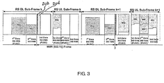
- Fig. 3 is an illustration of a frame structure for a relay station operating in a mobile Orthogonal Frequency Division Multiple Access (OFDMA) network having a base station and one or more mobile stations, according to an embodiment of the present invention.
- OFDMA Orthogonal Frequency Division Multiple Access
- Fig. 4 is a flowchart illustrating the method of structuring a time frame for a relay station operating in a mobile Orthogonal Frequency Division Multiple Access (OFDMA) network having a base station and one or more mobile stations, according to an embodiment of the present invention.
- OFDMA Orthogonal Frequency Division Multiple Access
- Fig. 1 is an illustrative example of an intra-cell topology involving a relay station operating in an OFDMA network.
- the network cell includes a base station (BS) 15, a relay station (RS) 55, a first mobile station (MS1) 25, a second mobile station (MS2) 35, and a third mobile station (MS3) 45.
- mobile station 25 is within range of base station 15, and, therefore, can communicate directly with base station 15 through the MS1-BS link 17.
- Mobile station 35 is within range of base station 15 and relay station 55 and, therefore, can communicate directly with base station 15 through the MS2-BS link 27, or, in the alternative, can communicate with base station 15 indirectly through relay station 55, using the MS2-RS link 77 and the RS-BS link 37.
- Mobile station 45 is out of range of base station 15 and, therefore, can only communicate with base station 15 indirectly through relay station 55, using MS3-RS link 67 and RS-BS link 37.
- relay station 55 In order to properly service both link 37 and link 67, relay station 55 would require two transceivers, thereby subjecting relay station 55 to significant interference between the concurrent transceiver operations within the same time frame.
- Various embodiments of the present invention provide a frame structure for a relay station operating in a mobile Orthogonal Frequency Division Multiple Access (OFDMA) network having a base station and one or more mobile stations.
- Various embodiments of the present invention provide a frame structure which includes a downlink sub-frame having three allocated time zones and an uplink sub-frame having three allocated time zones.
- Various embodiments of the present invention provide a downlink sub-frame having a first allocated time zone dedicated for transmission between the base station and relay station, a second allocated time zone dedicated for transmission between the base station and the one or more mobile stations, and a third allocated time zone dedicated for transmission between the relay station and the one or more mobile stations.
- Various embodiments of the present invention provide an uplink sub-frame having a first allocated time zone dedicated for transmission between the one or more mobile stations and the relay station, a second allocated time zone dedicated for transmission between the one or more mobile stations and the base station, and a third allocated time zone dedicated for transmission between the relay station and the base station. In this manner, interference between stations in the network can be greatly reduced and a relay station can be provided with a single, switched-transceiver architecture.
- Fig. 1 is only an illustrative example of an intra-cell topology involving a single relay station operating in an OFDMA network.
- the various embodiments of the present invention are not limited to an OFDMA network including only a single base station, a single relay station, and three mobile stations as illustrated in Fig. 1, but may include any wireless communication network supporting any number of base stations, relay stations, and mobile stations.
- Figs. 2 and 3 illustrate a frame structure and traffic activity for the base station 15 and the relay station 55, respectively, operating in the mobile OFDMA network illustrated in Fig. 1, according to an embodiment of the present invention.
- Each frame includes a downlink sub-frame and an uplink sub-frame. In order to simplify the illustration, only downlink control bursts are shown.
- Each downlink sub-frame is divided into a first allocated time zone dedicated for transmission bursts between base station 15 and relay station 55, a second allocated time zone dedicated for transmission bursts between base station 15 and mobile stations 25, 35, and 45, and a third allocated time zone dedicated for transmission bursts between relay station 55 and mobile stations 25, 35, and 45.
- Each uplink sub-frame is divided into a first allocated time zone dedicated for transmission bursts between one or more mobile stations 25, 35, and 45 and relay station 55, a second allocated time zone dedicated for transmission bursts between one or more mobile stations 25, 35, and 45 and base station 15, and a third allocated time zone dedicated for transmission bursts between relay station 55 and base station 15.
- downlink bursts from base station 15 dedicated to mobile station 45, through relay station 55 will be received in frame k by relay station 55 and relayed in frame k+1 to mobile station 45.
- relay station 55 With the assumption that no downlink bursts have been scheduled for mobile station 45, through relay station 55, in the frame k-1 (not shown), relay station 55 will transmit no downlink bursts to mobile station 45 in frame k.
- the various embodiments of the present invention are not limited to a frame structure with a frame relevance 1 implementation, but may include a frame structure with any frame relevance implementation.
- the downlink bursts from base station 15 dedicated to mobile station 45 in the first allocated time zone of the base station downlink sub-frame are received in the first allocated time zone of the relay station downlink sub-frame. Therefore, since no relay station activity is performed in the second allocated time zone of the relay station downlink sub-frame, this time zone may act as a time buffer between the first allocated time zone of the relay station downlink sub-frame and third allocated time zone of the relay station downlink sub-frame. In this manner, any burst received by the relay station 55 from the base station 15 can be transmitted to the mobile station 45 in the same time frame and any burst received by the relay station 55 from the mobile station 45 can be transmitted to the base station 15 in the same time frame.
- the physical layer (PHY) and MAC configuration of the relay station determine whether the relay station can support such a frame relevance 0 implementation.
- Various embodiments of the present invention provide for the first and third allocated time zones of the downlink sub-frame and the first and second allocated time zones of the uplink sub-frame to be subject to a dedicated allocation, for example, partially used sub-carriers (PUSC). Furthermore, various embodiments of the present invention provide for the second allocated time zone of the downlink sub-frame and the third allocated time zone of the uplink sub-frame to be subject to optional allocations.
- PUSC partially used sub-carriers
- the various embodiments of the present invention are not limited to a frame structure where the first and third allocated time zones of the downlink sub-frame and the first and second allocated time zones of the uplink sub-frame are subject to a dedicated allocation and the second allocated time zone of the downlink sub-frame and the third allocated time zone of the uplink sub-frame are subject to optional allocations, but may include any frame structure with any allocation type.
- Each OFDMA frame is started with a preamble burst 102 and 202, respectively, and an allocation burst 104 and 204, respectively.
- Allocation bursts 104 and 204 may be, for example, Mobile Application Part (MAP) bursts.
- Successive preamble bursts 102 and allocation bursts 104 delimit single, individual time frames for the base station.
- Successive preamble bursts 202 and allocation bursts 204 delimit single, individual time frames for the relay station.
- the preamble burst 102 and allocation burst 104 for the base station frame are provided prior to the first allocated time zone of the downlink sub-frame, as is conventional in networks operating under the Institute of Electrical and Electronics Engineers (IEEE) 802.16e standard.
- IEEE Institute of Electrical and Electronics Engineers
- the preamble burst 202 and allocation burst 204 for the relay station frame are provided prior to the third allocated time zone of the downlink sub-frame.
- the relay station frame as shown in Fig. 3, has an asymmetrical downlink/uplink structure when compared to the base station frame, as shown in Fig. 2.
- relay station having a shared (switched) transceiver can be allowed, providing for significant cost reduction.
- the relay station can be made capable of maintaining back ward compatibility with hardware operating under the IEEE 802.16e standard.
- Figs. 2-3 are only illustrative of frame structures and traffic activity for a base station and a relay station in a network having single relay station, a single base station, and three mobile stations operating in an OFDMA network.
- the various embodiments of the present invention are not limited to an OFDMA network including only a single relay station, a single base station, and three mobile stations, but may include any wireless communication network supporting any number of base stations, relay stations, and mobile stations.
- the first allocated time zone of the downlink sub-frame can be scheduled for downlink transmissions dedicated to all of the intra-cell relay stations and the first allocation is Partially Used Sub-carriers (PUSC).
- PUSC Partially Used Sub-carriers
- a second allocation may be defined. The various embodiments of the present invention are not limited to these allocations, but may include any allocation structure.
- the third allocated time zone of the downlink sub-frame and the third allocated time zone of the uplink sub-frame can be used by all the relay stations, subject to proper network management, targeting optimized intra-cell interference management.
- the first allocation is PUSC and a subsequent allocation could be defined.
- the various embodiments of the present invention are not limited to these allocations, but may include any allocation structure.
- the first allocated time zone of the uplink sub-frame can be used by all intra-cell relay stations subject to the same allocation usage.
- the first allocation is PUSC and a subsequent allocation could be defined.
- the various embodiments of the present invention are not limited to these allocations, but may include any allocation structure.
- Fig. 4 is a flowchart illustrating a procedure of structuring a time frame for a relay station operating in a mobile Orthogonal Frequency Division Multiple Access (OFDMA) network.
- OFDMA Orthogonal Frequency Division Multiple Access
- an uplink sub-frame of the time frame is divided into a first allocated time zone dedicated for transmission between the one or more mobile stations and the relay station, a second allocated time zone dedicated for transmission between the one or more mobile stations and the base station, and a third allocated time zone dedicated for transmission between the relay station and the base station.
- the process may further provide a preamble burst and an allocation burst (MAP burst) at the beginning of the third allocated time zone of the downlink sub-frame.
- MAP burst an allocation burst
- the present invention relates to frame structures for relay stations acting in OFDMA networks, and in particular, 802.16 networks.
- the present invention is not limited to any specific types of networks, and the frame structure and method of the relay station could be applied in various different types of wireless communications networks.
- the relay station may be subject to significant interference between these concurrent transceiver operations.
- the concurrent transmission of the transmitter of the relay station and the receiver of the relay station may lead to a severe degradation of any received signal by the relay station during that particular time frame.
- a relay station transmitting concurrently with a related anchor base station would cause a severe degradation of any signal received by a mobile station or another relay station located within the overlapping service area.
- the present invention relates to the IEEE 802.16 standard, which includes its amendments and extensions, such as, for example, IEEE 802.16e and IEEE 802.16j.
- the IEEE 802.16 standard is incorporated herein by reference in its entirety.
- the invention also provides a computer program or a computer program product for carrying out any of the methods described herein, and a computer readable medium having stored thereon a program for carrying out any of the methods described herein.
- a computer program embodying the invention may be stored on a computer-readable medium, or it could, for example, be in the form of a signal such as a downloadable data signal provided from an Internet website, or it could be in any other form.
Landscapes
- Engineering & Computer Science (AREA)
- Computer Networks & Wireless Communication (AREA)
- Signal Processing (AREA)
- Mobile Radio Communication Systems (AREA)
- Radio Relay Systems (AREA)
Abstract
Description
- The present application claims priority to provisional application titled "Frame Structure for Relay Stations Operating in Mobile WiMAX Networks", serial number
60/864,183, filed November 3, 2006 - Wireless communication networks have become increasingly popular and generally include a base station that provides service to a cell area located around the base station. Mobile stations (such as cell phones, etc.) are able to communicate with the base station when they are within the service area of the base station.
- However, in wireless communication networks, due to such effects as shadowing arising from blockage by buildings and other obstructions between transmission/reception antennas, there exist dead zones in which communication with the base station is not possible, despite being within the service area. To combat this problem, in an Orthogonal Frequency Division Multiple Access (OFDMA) network, such as, for example, a network based on the Institute of Electrical and Electronics Engineers (IEEE) 802.16 standard, relay stations are employed for providing enhanced transmission capabilities by acting as intermediaries between mobile stations operating in the network and the base station. In this manner, a mobile station that is incapable of connecting directly to a base station within its cell service area may still connect indirectly to the base station by first communicating with a relay station that does have a direct link, or possibly an indirect link, to the base station.
- Each relay station is provided with a hardware architecture for transmitting and receiving signals to and from other stations within the network. To this end, each relay station is generally provided with a double transceiver for covering both a link between the relay station and a base station and a link between the relay station and a mobile station.
- Various embodiments of the present invention provide a frame structure which includes (a) a downlink sub-frame having a first allocated time zone dedicated for transmission between the base station and relay station, a second allocated time zone dedicated for transmission between the base station and the one or more mobile stations, and a third allocated time zone dedicated for transmission between the relay station and the one or more mobile stations; and (b) an uplink sub-frame having a first allocated time zone dedicated for transmission between the one or more mobile stations and the relay station, a second allocated time zone dedicated for transmission between the one or more mobile stations and the base station, and a third allocated time zone dedicated for transmission between the relay station and the base station.
- Various embodiments of the present invention provide a method which includes (a) dividing a downlink sub-frame of the time frame into a first allocated time zone dedicated for transmission between the base station and relay station, a second allocated time zone dedicated for transmission between the base station and the one or more mobile stations, and a third allocated time zone dedicated for transmission between the relay station and the one or more mobile stations; and (b) dividing an uplink sub-frame of the time frame into a first allocated time zone dedicated for transmission between the one or more mobile stations and the relay station, a second allocated time zone dedicated for transmission between the one or more mobile stations and the base station, and a third allocated time zone dedicated for transmission between the relay station and the base station.
Further embodiments provide a base station, or a relay station or a mobile station using the frame structure defined to receive and transmit information and a transmission method in each of these stations. - The above embodiments of the present invention are simply examples, and all embodiments of the present invention are not limited to these examples.
- Additional advantages of the invention will be set forth in part in the description which follows, and, in part, will be obvious from the description, or may be learned by practice of the invention.
- These and other objects and advantages of the invention will become apparent and more readily appreciated from the following description of the preferred embodiments, taken in conjunction with the accompanying drawings of which:
- Fig. 1 is an illustration of an example of an intra-cell topology involving a relay station operating in an OFDMA network under the 802.16 standard.
- Fig. 2 is an illustration of a frame structure for a base station operating in a mobile Orthogonal Frequency Division Multiple Access (OFDMA) network having a base station and one or more mobile stations, according to an embodiment of the present invention.
- Fig. 3 is an illustration of a frame structure for a relay station operating in a mobile Orthogonal Frequency Division Multiple Access (OFDMA) network having a base station and one or more mobile stations, according to an embodiment of the present invention.
- Fig. 4 is a flowchart illustrating the method of structuring a time frame for a relay station operating in a mobile Orthogonal Frequency Division Multiple Access (OFDMA) network having a base station and one or more mobile stations, according to an embodiment of the present invention.
- Reference will now be made in detail to the present preferred embodiments of the present invention, examples of which are illustrated in the accompanying drawings, wherein like reference numerals refer to like elements throughout.
- Fig. 1 is an illustrative example of an intra-cell topology involving a relay station operating in an OFDMA network. The network cell includes a base station (BS) 15, a relay station (RS) 55, a first mobile station (MS1) 25, a second mobile station (MS2) 35, and a third mobile station (MS3) 45. In this example,
mobile station 25 is within range ofbase station 15, and, therefore, can communicate directly withbase station 15 through the MS1-BS link 17.Mobile station 35 is within range ofbase station 15 andrelay station 55 and, therefore, can communicate directly withbase station 15 through the MS2-BS link 27, or, in the alternative, can communicate withbase station 15 indirectly throughrelay station 55, using the MS2-RS link 77 and the RS-BS link 37.Mobile station 45 is out of range ofbase station 15 and, therefore, can only communicate withbase station 15 indirectly throughrelay station 55, using MS3-RSlink 67 and RS-BSlink 37. In order to properly service bothlink 37 andlink 67,relay station 55 would require two transceivers, thereby subjectingrelay station 55 to significant interference between the concurrent transceiver operations within the same time frame. - Various embodiments of the present invention provide a frame structure for a relay station operating in a mobile Orthogonal Frequency Division Multiple Access (OFDMA) network having a base station and one or more mobile stations. Various embodiments of the present invention provide a frame structure which includes a downlink sub-frame having three allocated time zones and an uplink sub-frame having three allocated time zones. Various embodiments of the present invention provide a downlink sub-frame having a first allocated time zone dedicated for transmission between the base station and relay station, a second allocated time zone dedicated for transmission between the base station and the one or more mobile stations, and a third allocated time zone dedicated for transmission between the relay station and the one or more mobile stations. Various embodiments of the present invention provide an uplink sub-frame having a first allocated time zone dedicated for transmission between the one or more mobile stations and the relay station, a second allocated time zone dedicated for transmission between the one or more mobile stations and the base station, and a third allocated time zone dedicated for transmission between the relay station and the base station. In this manner, interference between stations in the network can be greatly reduced and a relay station can be provided with a single, switched-transceiver architecture.
- Fig. 1 is only an illustrative example of an intra-cell topology involving a single relay station operating in an OFDMA network. The various embodiments of the present invention are not limited to an OFDMA network including only a single base station, a single relay station, and three mobile stations as illustrated in Fig. 1, but may include any wireless communication network supporting any number of base stations, relay stations, and mobile stations.
- Figs. 2 and 3 illustrate a frame structure and traffic activity for the
base station 15 and therelay station 55, respectively, operating in the mobile OFDMA network illustrated in Fig. 1, according to an embodiment of the present invention. Each frame includes a downlink sub-frame and an uplink sub-frame. In order to simplify the illustration, only downlink control bursts are shown. Each downlink sub-frame is divided into a first allocated time zone dedicated for transmission bursts betweenbase station 15 andrelay station 55, a second allocated time zone dedicated for transmission bursts betweenbase station 15 andmobile stations relay station 55 andmobile stations mobile stations relay station 55, a second allocated time zone dedicated for transmission bursts between one or moremobile stations base station 15, and a third allocated time zone dedicated for transmission bursts betweenrelay station 55 andbase station 15. - As shown in Figs. 2 and 3, downlink bursts from
base station 15 dedicated tomobile station 45, throughrelay station 55, will be received in frame k byrelay station 55 and relayed in frame k+1 tomobile station 45. With the assumption that no downlink bursts have been scheduled formobile station 45, throughrelay station 55, in the frame k-1 (not shown),relay station 55 will transmit no downlink bursts tomobile station 45 in frame k. This represents a frame structure with aframe relevance 1 implementation. The various embodiments of the present invention are not limited to a frame structure with aframe relevance 1 implementation, but may include a frame structure with any frame relevance implementation. - The downlink bursts from
base station 15 dedicated tomobile station 45 in the first allocated time zone of the base station downlink sub-frame are received in the first allocated time zone of the relay station downlink sub-frame. Therefore, since no relay station activity is performed in the second allocated time zone of the relay station downlink sub-frame, this time zone may act as a time buffer between the first allocated time zone of the relay station downlink sub-frame and third allocated time zone of the relay station downlink sub-frame. In this manner, any burst received by therelay station 55 from thebase station 15 can be transmitted to themobile station 45 in the same time frame and any burst received by therelay station 55 from themobile station 45 can be transmitted to thebase station 15 in the same time frame. This represents a frame structure with a frame relevance 0 implementation. The physical layer (PHY) and MAC configuration of the relay station determine whether the relay station can support such a frame relevance 0 implementation. - Various embodiments of the present invention provide for the first and third allocated time zones of the downlink sub-frame and the first and second allocated time zones of the uplink sub-frame to be subject to a dedicated allocation, for example, partially used sub-carriers (PUSC). Furthermore, various embodiments of the present invention provide for the second allocated time zone of the downlink sub-frame and the third allocated time zone of the uplink sub-frame to be subject to optional allocations. The various embodiments of the present invention are not limited to a frame structure where the first and third allocated time zones of the downlink sub-frame and the first and second allocated time zones of the uplink sub-frame are subject to a dedicated allocation and the second allocated time zone of the downlink sub-frame and the third allocated time zone of the uplink sub-frame are subject to optional allocations, but may include any frame structure with any allocation type.
- Each OFDMA frame is started with a
preamble burst allocation burst Allocation bursts preamble bursts 102 andallocation bursts 104 delimit single, individual time frames for the base station.Successive preamble bursts 202 andallocation bursts 204 delimit single, individual time frames for the relay station. Thepreamble burst 102 andallocation burst 104 for the base station frame are provided prior to the first allocated time zone of the downlink sub-frame, as is conventional in networks operating under the Institute of Electrical and Electronics Engineers (IEEE) 802.16e standard. However, thepreamble burst 202 andallocation burst 204 for the relay station frame are provided prior to the third allocated time zone of the downlink sub-frame. As such, the relay station frame, as shown in Fig. 3, has an asymmetrical downlink/uplink structure when compared to the base station frame, as shown in Fig. 2. - Thus, there are typically no concurrent transmit/receive operations at the relay station level and transmit/receive activity can be synchronized between the base station and the relay station such that intra-cell interference is avoided. Therefore, a relay station having a shared (switched) transceiver can be allowed, providing for significant cost reduction. Furthermore, the relay station can be made capable of maintaining back ward compatibility with hardware operating under the IEEE 802.16e standard.
- Figs. 2-3 are only illustrative of frame structures and traffic activity for a base station and a relay station in a network having single relay station, a single base station, and three mobile stations operating in an OFDMA network. The various embodiments of the present invention are not limited to an OFDMA network including only a single relay station, a single base station, and three mobile stations, but may include any wireless communication network supporting any number of base stations, relay stations, and mobile stations.
- Where multiple relay stations are operating within a cell of an OFDMA network, the first allocated time zone of the downlink sub-frame can be scheduled for downlink transmissions dedicated to all of the intra-cell relay stations and the first allocation is Partially Used Sub-carriers (PUSC). A second allocation may be defined. The various embodiments of the present invention are not limited to these allocations, but may include any allocation structure.
- The third allocated time zone of the downlink sub-frame and the third allocated time zone of the uplink sub-frame can be used by all the relay stations, subject to proper network management, targeting optimized intra-cell interference management. The first allocation is PUSC and a subsequent allocation could be defined. The various embodiments of the present invention are not limited to these allocations, but may include any allocation structure.
- The first allocated time zone of the uplink sub-frame can be used by all intra-cell relay stations subject to the same allocation usage. The first allocation is PUSC and a subsequent allocation could be defined. The various embodiments of the present invention are not limited to these allocations, but may include any allocation structure.
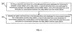
- Fig. 4 is a flowchart illustrating a procedure of structuring a time frame for a relay station operating in a mobile Orthogonal Frequency Division Multiple Access (OFDMA) network. Referring now to Fig. 4, in
operation 300, a downlink sub-frame of the time frame is divided into a first allocated time zone dedicated for transmission between the base station and relay station, a second allocated time zone dedicated for transmission between the base station and the one or more mobile stations, and a third allocated time zone dedicated for transmission between the relay station and the one or more mobile stations. - From
operation 300, the process moves to operation 400, where an uplink sub-frame of the time frame is divided into a first allocated time zone dedicated for transmission between the one or more mobile stations and the relay station, a second allocated time zone dedicated for transmission between the one or more mobile stations and the base station, and a third allocated time zone dedicated for transmission between the relay station and the base station. - The process may further provide a preamble burst and an allocation burst (MAP burst) at the beginning of the third allocated time zone of the downlink sub-frame. By providing the preamble burst and the allocation burst at the beginning of the third allocated time zone of the downlink sub-frame, there are no concurrent transmit/receive operations at the relay station level and transmit/receive activity is synchronized between the base station and the relay station such that intra-cell interference is avoided.
- The present invention relates to frame structures for relay stations acting in OFDMA networks, and in particular, 802.16 networks. However, the present invention is not limited to any specific types of networks, and the frame structure and method of the relay station could be applied in various different types of wireless communications networks. Furthermore, it is desirable for a relay station to be backwards compatible with all base stations and mobile stations operating in such a network, for example in WiMAX networks based on the IEEE 802.16e standard.
- The relay station may be subject to significant interference between these concurrent transceiver operations. The concurrent transmission of the transmitter of the relay station and the receiver of the relay station may lead to a severe degradation of any received signal by the relay station during that particular time frame. Furthermore, a relay station transmitting concurrently with a related anchor base station would cause a severe degradation of any signal received by a mobile station or another relay station located within the overlapping service area. There is also a disadvantage in that it is expensive to provide such a double transceiver relay station. Thus, it is also desirable for a switched-transceiver architecture of a relay station to be supported by the frame structure.
- The present invention relates to the IEEE 802.16 standard, which includes its amendments and extensions, such as, for example, IEEE 802.16e and IEEE 802.16j. The IEEE 802.16 standard is incorporated herein by reference in its entirety.
- Application No. 11/691,785, titled SWITCHABLE TRANSCEIVER FOR RELAY STATION, inventors Aram Sukiasyan, Chad Gilbertson, and Dorin Viorel, filed on March 27, 2007, attorney docket number 1974.1006, is incorporated herein by reference in its entirety.
- Although a few preferred embodiments of the present invention have been shown and described, it would be appreciated by those skilled in the art that changes may be made in these embodiments without departing from the principles and spirit of the invention, the scope of which is defined in the claims and their equivalents.
- In any of the above aspects, the various features may be implemented in hardware, or as software modules running on one or more processors. Features of one aspect may be applied to any of the other aspects.
- The invention also provides a computer program or a computer program product for carrying out any of the methods described herein, and a computer readable medium having stored thereon a program for carrying out any of the methods described herein. A computer program embodying the invention may be stored on a computer-readable medium, or it could, for example, be in the form of a signal such as a downloadable data signal provided from an Internet website, or it could be in any other form.
Claims (15)
- A frame structure for a relay station operating in a mobile Orthogonal Frequency Division Multiple Access (OFDMA) network, comprising:a downlink sub-frame having a first allocated time zone dedicated for transmission between a base station in the network and the relay station, a second allocated time zone dedicated for transmission between the base station and a mobile station in the network, and a third allocated time zone dedicated for transmission between the relay station and the mobile station; andan uplink sub-frame having a first allocated time zone dedicated for transmission between the mobile station and the relay station, a second allocated time zone dedicated for transmission between the mobile station and the base station, and a third allocated time zone dedicated for transmission between the relay station and the base station.
- The frame structure of claim 1, wherein a preamble burst and an allocation burst are each provided at the beginning of the third allocated time zone of the downlink sub-frame.
- A method of structuring a time frame for a relay station operating in a mobile Orthogonal Frequency Division Multiple Access (OFDMA) network, comprising:dividing a downlink sub-frame of the time frame into a first allocated time zone dedicated for transmission between a base station in the network and the relay station, a second allocated time zone dedicated for transmission between the base station and a mobile station in the network, and a third allocated time zone dedicated for transmission between the relay station and the mobile station; anddividing an uplink sub-frame of the time frame into a first allocated time zone dedicated for transmission between the mobile station and the relay station, a second allocated time zone dedicated for transmission between the mobile station and the base station, and a third allocated time zone dedicated for transmission between the relay station and the base station.
- The method of claim 3, further comprising providing a preamble burst and an allocation burst at the beginning of the third allocated time zone of the downlink sub-frame.
- The frame structure or method of any of the preceding claims, wherein a single time frame is delimited by successive preamble bursts.
- The frame structure or method of any of the preceding claims, wherein the frame structure has a frame relevance of 1.
- The frame structure or method of any of claims 1 to 5, wherein the frame structure has a frame relevance of 0.
- The frame structure or method of any of the preceding claims, wherein the first and third allocated time zones of the downlink sub-frame and the first and second allocated time zones of the uplink sub-frame are subject to a dedicated allocation.
- The frame structure or method of any of the preceding claims, wherein the second allocated time zone of the downlink sub-frame and the third allocated time zone of the uplink sub-frame are subject to optional allocations.
- The frame structure or method of claim 9, wherein the first allocation is partially used sub-carriers (PUSC).
- The frame structure or method of any of the preceding claims, wherein multiple relay stations within the same network cell share the first and third allocated time zones of the downlink sub-frame and the first and third allocated time zones of the uplink sub-frame.
- The frame structure or method of any of the preceding claims, wherein the OFDMA network is a network under the Institute of Electrical and Electronics Engineers (IEEE) 802.16 standard.
- A transmission method in a relay station comprising adopting a time frame as defined in any of the preceding claims and transmitting information on the uplink and/or downlink using the time allocations set out in the time frame structure.
- A relay station in an OFDMA network, comprising:transmission preparation means for preparing information for transmission by structuring it into a frame or frames as defined in any of claims 1 to 13; andtransmission and reception means for transmitting and receiving information so structured.
- A computer program which, when executed on a telecommunications station, carries out the method defined in any of the preceding method claims.
Applications Claiming Priority (2)
| Application Number | Priority Date | Filing Date | Title |
|---|---|---|---|
| US86418306P | 2006-11-03 | 2006-11-03 | |
| US11/927,035 US7990906B2 (en) | 2006-11-03 | 2007-10-29 | Frame structure for a relay station operating in mobile networks |
Publications (2)
| Publication Number | Publication Date |
|---|---|
| EP1919143A2 true EP1919143A2 (en) | 2008-05-07 |
| EP1919143A3 EP1919143A3 (en) | 2011-04-13 |
Family
ID=39125263
Family Applications (1)
| Application Number | Title | Priority Date | Filing Date |
|---|---|---|---|
| EP07119936A Withdrawn EP1919143A3 (en) | 2006-11-03 | 2007-11-02 | Frame structure for a relay station operating in mobile networks |
Country Status (4)
| Country | Link |
|---|---|
| US (1) | US7990906B2 (en) |
| EP (1) | EP1919143A3 (en) |
| JP (1) | JP2008178074A (en) |
| KR (1) | KR100943129B1 (en) |
Cited By (11)
| Publication number | Priority date | Publication date | Assignee | Title |
|---|---|---|---|---|
| WO2009149565A1 (en) | 2008-06-12 | 2009-12-17 | Nortel Networks Limited | Method and system using relays with aggregated spectrum |
| WO2010039739A3 (en) * | 2008-09-30 | 2010-07-08 | Qualcomm Incorporated | Techniques for supporting relay operation in wireless communication systems |
| WO2010149213A1 (en) | 2009-06-24 | 2010-12-29 | Nokia Siemens Networks Oy | Network element for changing the timeslot type according to the received information |
| GB2478810A (en) * | 2009-12-31 | 2011-09-21 | Intel Corp | Distributed simultaneous transmit and receive relay station |
| WO2011163021A1 (en) * | 2010-06-21 | 2011-12-29 | Alcatel-Lucent Usa Inc. | Method of uplink control channel allocation for a relay backhaul link |
| CN102449929A (en) * | 2009-04-06 | 2012-05-09 | 三星电子株式会社 | Design of control and data channels for advanced relay operation |
| US20130058304A1 (en) * | 2010-05-11 | 2013-03-07 | Lg Electronics Inc. | Method and device for receiving downlink signals |
| EP2523488A4 (en) * | 2010-01-08 | 2013-06-12 | Ntt Docomo Inc | MOBILE COMMUNICATION SYSTEM AND RADIO BASE STATION |
| US9203501B2 (en) | 2008-10-24 | 2015-12-01 | Huawei Technologies Co., Ltd. | Relay transmission method and apparatus |
| US9203564B2 (en) | 2008-10-20 | 2015-12-01 | Qualcomm Incorporated | Data transmission via a relay station in a wireless communication system |
| US20170150481A1 (en) * | 2015-11-23 | 2017-05-25 | Qualcomm Incorporated | Traffic scheduling in a multi-hop communications system |
Families Citing this family (21)
| Publication number | Priority date | Publication date | Assignee | Title |
|---|---|---|---|---|
| US8462676B2 (en) * | 2006-10-17 | 2013-06-11 | Intel Corporation | Frame structure for support of large delay spread deployment scenarios |
| JP4983208B2 (en) * | 2006-11-07 | 2012-07-25 | 富士通株式会社 | Relay station, wireless communication method |
| US7894388B2 (en) * | 2007-01-05 | 2011-02-22 | Motorola Solutions, Inc. | Method and apparatus for relay zone bandwidth allocation |
| CN101345544B (en) * | 2007-07-09 | 2012-10-10 | 电信科学技术研究院 | Method and system for wireless transmission adopting Relay supported frame structure |
| US8428608B2 (en) * | 2007-12-21 | 2013-04-23 | Samsung Electronics Co., Ltd. | Method and system for resource allocation in relay enhanced cellular systems |
| US8259630B2 (en) * | 2007-12-21 | 2012-09-04 | Samsung Electronics Co., Ltd. | Method and system for subcarrier allocation in relay enhanced cellular systems with resource reuse |
| US8229449B2 (en) * | 2007-12-21 | 2012-07-24 | Samsung Electronics Co., Ltd. | Method and system for allocating subcarrier frequency resources for a relay enhanced cellular communication system |
| KR101400715B1 (en) * | 2008-04-02 | 2014-05-29 | 연세대학교 산학협력단 | Apparatus and method for communication using cooperative tranmission and network coding transmission |
| KR101527978B1 (en) * | 2008-08-06 | 2015-06-18 | 엘지전자 주식회사 | Method and apparatus for communicating using sub-frames between base stations and repeaters |
| US8355734B2 (en) * | 2008-08-07 | 2013-01-15 | Apple Inc. | Wireless system |
| JP5246263B2 (en) * | 2008-09-11 | 2013-07-24 | 富士通株式会社 | Wireless relay system and method of using wireless frame |
| KR101527977B1 (en) * | 2008-10-27 | 2015-06-15 | 엘지전자 주식회사 | Method of operating a repeater in a wireless communication system |
| KR101075964B1 (en) * | 2009-02-02 | 2011-10-21 | 아주대학교산학협력단 | Apparatus and method for relaying multiple links in a communication system |
| US8301177B2 (en) | 2009-03-03 | 2012-10-30 | Intel Corporation | Efficient paging operation for femtocell deployment |
| US20100260113A1 (en) * | 2009-04-10 | 2010-10-14 | Samsung Electronics Co., Ltd. | Adaptive resource allocation protocol for newly joining relay stations in relay enhanced cellular systems |
| WO2010143867A2 (en) * | 2009-06-08 | 2010-12-16 | 엘지전자 주식회사 | Method in which a relay allocates carriers on a backhaul link and an access link in a multi-carrier wireless communication system |
| WO2011019223A2 (en) * | 2009-08-12 | 2011-02-17 | Lg Electronics Inc. | Relay station and method of relay station transmitting backhaul uplink signal |
| KR20110031111A (en) * | 2009-09-18 | 2011-03-24 | 엘지전자 주식회사 | Method and apparatus for setting a frame in a wireless communication system including a relay station |
| CN102055518A (en) * | 2009-10-30 | 2011-05-11 | 中兴通讯股份有限公司 | Method and system for timing subframe |
| KR101781356B1 (en) * | 2011-01-28 | 2017-09-25 | 삼성전자주식회사 | Method and apparatus for supporting isolated terminal in wireless communication system |
| WO2012138112A2 (en) * | 2011-04-04 | 2012-10-11 | 엘지전자 주식회사 | Method for transmitting uplink control information in a wireless communication system and device for same. |
Family Cites Families (9)
| Publication number | Priority date | Publication date | Assignee | Title |
|---|---|---|---|---|
| KR100657506B1 (en) * | 2003-10-30 | 2006-12-13 | 한국전자통신연구원 | Method for embodying downlink frame in wireless communication system using orthogonal frequency division multiple access method |
| JP4220999B2 (en) * | 2003-12-01 | 2009-02-04 | パナソニック株式会社 | Receiving device, receiving method, and semiconductor integrated circuit device |
| DE60329039D1 (en) | 2003-12-30 | 2009-10-08 | Nokia Corp | ASYMMETRICAL DATA CONNECTION COMMUNICATION SYSTEM WITH RELAY STATIONS |
| JP4652846B2 (en) | 2004-03-11 | 2011-03-16 | パナソニック株式会社 | Communication terminal device and communication relay method |
| KR101048960B1 (en) * | 2004-11-01 | 2011-07-12 | 에스케이 텔레콤주식회사 | Signal Transition Delay Time Compensation Switching Timing Generation Method for Optical Repeater and Optical Repeater for Signal Delay Compensation Between Base Station and Repeater in OBD-TD WiBro System |
| KR100866334B1 (en) * | 2005-09-29 | 2008-10-31 | 삼성전자주식회사 | Apparatus and method for supporting multiple links in a multihop relay cellular network |
| KR100893832B1 (en) * | 2005-10-18 | 2009-04-17 | 삼성전자주식회사 | Apparatus and method for supporting multiple links in a multi-hop relay cellular network using two frequency bands |
| WO2007053954A1 (en) | 2005-11-10 | 2007-05-18 | Nortel Networks Limited | Zones for wireless networks with relays |
| JP4899087B2 (en) * | 2006-03-24 | 2012-03-21 | 富士通株式会社 | Transmission system |
-
2007
- 2007-10-29 US US11/927,035 patent/US7990906B2/en active Active
- 2007-11-02 JP JP2007286751A patent/JP2008178074A/en not_active Withdrawn
- 2007-11-02 EP EP07119936A patent/EP1919143A3/en not_active Withdrawn
- 2007-11-05 KR KR1020070112356A patent/KR100943129B1/en not_active Expired - Fee Related
Cited By (27)
| Publication number | Priority date | Publication date | Assignee | Title |
|---|---|---|---|---|
| WO2009149565A1 (en) | 2008-06-12 | 2009-12-17 | Nortel Networks Limited | Method and system using relays with aggregated spectrum |
| US9686061B2 (en) | 2008-06-12 | 2017-06-20 | Apple Inc. | Method and system using relays with aggregated spectrum |
| EP2286626A4 (en) * | 2008-06-12 | 2012-03-14 | Nortel Networks Ltd | METHOD AND SYSTEM USING RELAYS WITH AGGREGATED SPECTRUM |
| US8804598B2 (en) | 2008-06-12 | 2014-08-12 | Apple Inc. | Method and system using relays with aggregated spectrum |
| WO2010039739A3 (en) * | 2008-09-30 | 2010-07-08 | Qualcomm Incorporated | Techniques for supporting relay operation in wireless communication systems |
| US9294219B2 (en) | 2008-09-30 | 2016-03-22 | Qualcomm Incorporated | Techniques for supporting relay operation in wireless communication systems |
| US8971241B2 (en) | 2008-09-30 | 2015-03-03 | Qualcolmm Incorporated | Techniques for supporting relay operation in wireless communication systems |
| US9203564B2 (en) | 2008-10-20 | 2015-12-01 | Qualcomm Incorporated | Data transmission via a relay station in a wireless communication system |
| US9203501B2 (en) | 2008-10-24 | 2015-12-01 | Huawei Technologies Co., Ltd. | Relay transmission method and apparatus |
| CN103888998A (en) * | 2009-04-06 | 2014-06-25 | 三星电子株式会社 | Design Of Control And Data Channels For Advanced Relay Operation |
| CN102449929A (en) * | 2009-04-06 | 2012-05-09 | 三星电子株式会社 | Design of control and data channels for advanced relay operation |
| CN102449929B (en) * | 2009-04-06 | 2015-11-25 | 三星电子株式会社 | Relay station for wireless communication network, wireless communication system and relay communication method |
| US8929303B2 (en) | 2009-04-06 | 2015-01-06 | Samsung Electronics Co., Ltd. | Control and data channels for advanced relay operation |
| WO2010149213A1 (en) | 2009-06-24 | 2010-12-29 | Nokia Siemens Networks Oy | Network element for changing the timeslot type according to the received information |
| US8958358B2 (en) | 2009-06-24 | 2015-02-17 | Nokia Siemens Networks Oy | Network element for changing the timeslot type according to the received information |
| GB2478810A (en) * | 2009-12-31 | 2011-09-21 | Intel Corp | Distributed simultaneous transmit and receive relay station |
| GB2478810B (en) * | 2009-12-31 | 2012-03-21 | Intel Corp | Distributed simultaneous transmit and receive relay system |
| US8913545B2 (en) | 2010-01-08 | 2014-12-16 | Ntt Docomo, Inc. | Mobile communication system and radio base station |
| US9001705B2 (en) | 2010-01-08 | 2015-04-07 | Ntt Docomo, Inc. | Mobile communication system and radio base station |
| EP2523488A4 (en) * | 2010-01-08 | 2013-06-12 | Ntt Docomo Inc | MOBILE COMMUNICATION SYSTEM AND RADIO BASE STATION |
| RU2517689C2 (en) * | 2010-01-08 | 2014-05-27 | Нтт Докомо, Инк. | Mobile communication system and radio base station |
| US8958382B2 (en) * | 2010-05-11 | 2015-02-17 | Lg Electronics Inc. | Method and device for receiving downlink signals |
| US20130058304A1 (en) * | 2010-05-11 | 2013-03-07 | Lg Electronics Inc. | Method and device for receiving downlink signals |
| WO2011163021A1 (en) * | 2010-06-21 | 2011-12-29 | Alcatel-Lucent Usa Inc. | Method of uplink control channel allocation for a relay backhaul link |
| CN103109472A (en) * | 2010-06-21 | 2013-05-15 | 阿尔卡特朗讯 | Method for uplink control channel allocation of relay backhaul link |
| US20170150481A1 (en) * | 2015-11-23 | 2017-05-25 | Qualcomm Incorporated | Traffic scheduling in a multi-hop communications system |
| US10694498B2 (en) * | 2015-11-23 | 2020-06-23 | Qualcomm Incorporated | Traffic scheduling in a multi-hop communications system |
Also Published As
| Publication number | Publication date |
|---|---|
| EP1919143A3 (en) | 2011-04-13 |
| JP2008178074A (en) | 2008-07-31 |
| US20080107062A1 (en) | 2008-05-08 |
| KR20080040616A (en) | 2008-05-08 |
| KR100943129B1 (en) | 2010-02-18 |
| US7990906B2 (en) | 2011-08-02 |
Similar Documents
| Publication | Publication Date | Title |
|---|---|---|
| EP1919143A2 (en) | Frame structure for a relay station operating in mobile networks | |
| US12082264B2 (en) | Method and apparatus for control resource set configuration for 5G next radio system | |
| US9801160B2 (en) | Method for allocating reference signals of a backhaul link in a relay communication system, and method and apparatus for transmitting/receiving data using the same | |
| US8218469B2 (en) | Wireless relay communication system and method | |
| CN102388545B (en) | Signal transmission method and device in relay communication system | |
| US11564235B2 (en) | Dynamic indication of the TCI/QCL for dynamic coresets | |
| US11729802B2 (en) | Techniques for addressing IAB node switching time | |
| US20100290372A1 (en) | Method for multiple tdd systems coexistence | |
| WO2021142754A1 (en) | Method and apparatus for uplink transmission | |
| CN115066950A (en) | Resource configuration method and network equipment | |
| US20250324415A1 (en) | Methods and apparatuses for signaling framework for flexible beam management | |
| EP4598104A1 (en) | Device and method for performing resource setting in wireless communication system | |
| WO2012165067A1 (en) | Wireless resource allocation method, wireless resource allocation device, and communication system | |
| JP7755649B2 (en) | Terminal, wireless communication system, and wireless communication method | |
| EP4615144A2 (en) | Method and devices for receiving and transmitting information | |
| EP4510747A1 (en) | Method for operating device in wireless communication system and device using same method | |
| US20240057191A1 (en) | Method and device for receiving and transmitting information | |
| US11770166B2 (en) | Dynamic scheduling of user equipment (UE) antenna resources | |
| KR20250037750A (en) | Method and device for transmitting and receiving information | |
| EP4598217A1 (en) | Method for performing communication in wireless communication system and device therefor | |
| WO2020030255A1 (en) | Reducing dmrs overhead | |
| US20250055610A1 (en) | Method for configuring resources, terminal, and network device | |
| EP4572213A1 (en) | Method for communicating and device for same in wireless communication system | |
| CN119111051A (en) | Operation method of device in wireless communication system and device using the same | |
| US10447456B2 (en) | Method for limiting spurious emission and user equipment performing the method |
Legal Events
| Date | Code | Title | Description |
|---|---|---|---|
| PUAI | Public reference made under article 153(3) epc to a published international application that has entered the european phase |
Free format text: ORIGINAL CODE: 0009012 |
|
| AK | Designated contracting states |
Kind code of ref document: A2 Designated state(s): AT BE BG CH CY CZ DE DK EE ES FI FR GB GR HU IE IS IT LI LT LU LV MC MT NL PL PT RO SE SI SK TR |
|
| AX | Request for extension of the european patent |
Extension state: AL BA HR MK RS |
|
| RAP1 | Party data changed (applicant data changed or rights of an application transferred) |
Owner name: FUJITSU MICROELECTRONICS LIMITED |
|
| RAP1 | Party data changed (applicant data changed or rights of an application transferred) |
Owner name: FUJITSU SEMICONDUCTOR LIMITED |
|
| PUAL | Search report despatched |
Free format text: ORIGINAL CODE: 0009013 |
|
| REG | Reference to a national code |
Ref country code: DE Ref legal event code: R079 Free format text: PREVIOUS MAIN CLASS: H04L0012560000 Ipc: H04W0072040000 |
|
| AK | Designated contracting states |
Kind code of ref document: A3 Designated state(s): AT BE BG CH CY CZ DE DK EE ES FI FR GB GR HU IE IS IT LI LT LU LV MC MT NL PL PT RO SE SI SK TR |
|
| AX | Request for extension of the european patent |
Extension state: AL BA HR MK RS |
|
| RIC1 | Information provided on ipc code assigned before grant |
Ipc: H04W 84/04 20090101ALN20110304BHEP Ipc: H04W 72/04 20090101AFI20110304BHEP |
|
| AKY | No designation fees paid | ||
| REG | Reference to a national code |
Ref country code: DE Ref legal event code: R108 |
|
| REG | Reference to a national code |
Ref country code: DE Ref legal event code: R108 Effective date: 20111221 |
|
| STAA | Information on the status of an ep patent application or granted ep patent |
Free format text: STATUS: THE APPLICATION IS DEEMED TO BE WITHDRAWN |
|
| 18D | Application deemed to be withdrawn |
Effective date: 20111014 |