EP1919098A1 - Receiver apparatus, transmitter apparatus and methods for providing precoding information - Google Patents
Receiver apparatus, transmitter apparatus and methods for providing precoding information Download PDFInfo
- Publication number
- EP1919098A1 EP1919098A1 EP06022649A EP06022649A EP1919098A1 EP 1919098 A1 EP1919098 A1 EP 1919098A1 EP 06022649 A EP06022649 A EP 06022649A EP 06022649 A EP06022649 A EP 06022649A EP 1919098 A1 EP1919098 A1 EP 1919098A1
- Authority
- EP
- European Patent Office
- Prior art keywords
- precoding information
- matrix
- precoding
- codebook
- absolute
- Prior art date
- Legal status (The legal status is an assumption and is not a legal conclusion. Google has not performed a legal analysis and makes no representation as to the accuracy of the status listed.)
- Granted
Links
Images






Classifications
-
- H—ELECTRICITY
- H04—ELECTRIC COMMUNICATION TECHNIQUE
- H04L—TRANSMISSION OF DIGITAL INFORMATION, e.g. TELEGRAPHIC COMMUNICATION
- H04L25/00—Baseband systems
- H04L25/02—Details ; arrangements for supplying electrical power along data transmission lines
- H04L25/03—Shaping networks in transmitter or receiver, e.g. adaptive shaping networks
- H04L25/03006—Arrangements for removing intersymbol interference
- H04L25/03343—Arrangements at the transmitter end
-
- H—ELECTRICITY
- H04—ELECTRIC COMMUNICATION TECHNIQUE
- H04B—TRANSMISSION
- H04B7/00—Radio transmission systems, i.e. using radiation field
- H04B7/02—Diversity systems; Multi-antenna system, i.e. transmission or reception using multiple antennas
- H04B7/04—Diversity systems; Multi-antenna system, i.e. transmission or reception using multiple antennas using two or more spaced independent antennas
- H04B7/0413—MIMO systems
- H04B7/0417—Feedback systems
-
- H—ELECTRICITY
- H04—ELECTRIC COMMUNICATION TECHNIQUE
- H04B—TRANSMISSION
- H04B7/00—Radio transmission systems, i.e. using radiation field
- H04B7/02—Diversity systems; Multi-antenna system, i.e. transmission or reception using multiple antennas
- H04B7/04—Diversity systems; Multi-antenna system, i.e. transmission or reception using multiple antennas using two or more spaced independent antennas
- H04B7/06—Diversity systems; Multi-antenna system, i.e. transmission or reception using multiple antennas using two or more spaced independent antennas at the transmitting station
- H04B7/0613—Diversity systems; Multi-antenna system, i.e. transmission or reception using multiple antennas using two or more spaced independent antennas at the transmitting station using simultaneous transmission
- H04B7/0615—Diversity systems; Multi-antenna system, i.e. transmission or reception using multiple antennas using two or more spaced independent antennas at the transmitting station using simultaneous transmission of weighted versions of same signal
- H04B7/0619—Diversity systems; Multi-antenna system, i.e. transmission or reception using multiple antennas using two or more spaced independent antennas at the transmitting station using simultaneous transmission of weighted versions of same signal using feedback from receiving side
- H04B7/0621—Feedback content
- H04B7/0634—Antenna weights or vector/matrix coefficients
-
- H—ELECTRICITY
- H04—ELECTRIC COMMUNICATION TECHNIQUE
- H04B—TRANSMISSION
- H04B7/00—Radio transmission systems, i.e. using radiation field
- H04B7/02—Diversity systems; Multi-antenna system, i.e. transmission or reception using multiple antennas
- H04B7/04—Diversity systems; Multi-antenna system, i.e. transmission or reception using multiple antennas using two or more spaced independent antennas
- H04B7/06—Diversity systems; Multi-antenna system, i.e. transmission or reception using multiple antennas using two or more spaced independent antennas at the transmitting station
- H04B7/0613—Diversity systems; Multi-antenna system, i.e. transmission or reception using multiple antennas using two or more spaced independent antennas at the transmitting station using simultaneous transmission
- H04B7/0615—Diversity systems; Multi-antenna system, i.e. transmission or reception using multiple antennas using two or more spaced independent antennas at the transmitting station using simultaneous transmission of weighted versions of same signal
- H04B7/0619—Diversity systems; Multi-antenna system, i.e. transmission or reception using multiple antennas using two or more spaced independent antennas at the transmitting station using simultaneous transmission of weighted versions of same signal using feedback from receiving side
- H04B7/0636—Feedback format
- H04B7/0639—Using selective indices, e.g. of a codebook, e.g. pre-distortion matrix index [PMI] or for beam selection
-
- H—ELECTRICITY
- H04—ELECTRIC COMMUNICATION TECHNIQUE
- H04B—TRANSMISSION
- H04B7/00—Radio transmission systems, i.e. using radiation field
- H04B7/02—Diversity systems; Multi-antenna system, i.e. transmission or reception using multiple antennas
- H04B7/04—Diversity systems; Multi-antenna system, i.e. transmission or reception using multiple antennas using two or more spaced independent antennas
- H04B7/06—Diversity systems; Multi-antenna system, i.e. transmission or reception using multiple antennas using two or more spaced independent antennas at the transmitting station
- H04B7/0613—Diversity systems; Multi-antenna system, i.e. transmission or reception using multiple antennas using two or more spaced independent antennas at the transmitting station using simultaneous transmission
- H04B7/0615—Diversity systems; Multi-antenna system, i.e. transmission or reception using multiple antennas using two or more spaced independent antennas at the transmitting station using simultaneous transmission of weighted versions of same signal
- H04B7/0619—Diversity systems; Multi-antenna system, i.e. transmission or reception using multiple antennas using two or more spaced independent antennas at the transmitting station using simultaneous transmission of weighted versions of same signal using feedback from receiving side
- H04B7/0636—Feedback format
- H04B7/0641—Differential feedback
-
- H—ELECTRICITY
- H04—ELECTRIC COMMUNICATION TECHNIQUE
- H04B—TRANSMISSION
- H04B7/00—Radio transmission systems, i.e. using radiation field
- H04B7/02—Diversity systems; Multi-antenna system, i.e. transmission or reception using multiple antennas
- H04B7/04—Diversity systems; Multi-antenna system, i.e. transmission or reception using multiple antennas using two or more spaced independent antennas
- H04B7/06—Diversity systems; Multi-antenna system, i.e. transmission or reception using multiple antennas using two or more spaced independent antennas at the transmitting station
- H04B7/0613—Diversity systems; Multi-antenna system, i.e. transmission or reception using multiple antennas using two or more spaced independent antennas at the transmitting station using simultaneous transmission
- H04B7/0615—Diversity systems; Multi-antenna system, i.e. transmission or reception using multiple antennas using two or more spaced independent antennas at the transmitting station using simultaneous transmission of weighted versions of same signal
- H04B7/0619—Diversity systems; Multi-antenna system, i.e. transmission or reception using multiple antennas using two or more spaced independent antennas at the transmitting station using simultaneous transmission of weighted versions of same signal using feedback from receiving side
- H04B7/0636—Feedback format
- H04B7/0645—Variable feedback
- H04B7/065—Variable contents, e.g. long-term or short-short
-
- H—ELECTRICITY
- H04—ELECTRIC COMMUNICATION TECHNIQUE
- H04L—TRANSMISSION OF DIGITAL INFORMATION, e.g. TELEGRAPHIC COMMUNICATION
- H04L25/00—Baseband systems
- H04L25/02—Details ; arrangements for supplying electrical power along data transmission lines
- H04L25/03—Shaping networks in transmitter or receiver, e.g. adaptive shaping networks
- H04L25/03006—Arrangements for removing intersymbol interference
- H04L2025/0335—Arrangements for removing intersymbol interference characterised by the type of transmission
- H04L2025/03375—Passband transmission
- H04L2025/03414—Multicarrier
-
- H—ELECTRICITY
- H04—ELECTRIC COMMUNICATION TECHNIQUE
- H04L—TRANSMISSION OF DIGITAL INFORMATION, e.g. TELEGRAPHIC COMMUNICATION
- H04L25/00—Baseband systems
- H04L25/02—Details ; arrangements for supplying electrical power along data transmission lines
- H04L25/03—Shaping networks in transmitter or receiver, e.g. adaptive shaping networks
- H04L25/03006—Arrangements for removing intersymbol interference
- H04L2025/03777—Arrangements for removing intersymbol interference characterised by the signalling
- H04L2025/03802—Signalling on the reverse channel
- H04L2025/03808—Transmission of equaliser coefficients
Definitions
- the present invention is in the field of multiple-input-multiple-output (MIMO) transmission as it is more and more used in mobile communication scenarios and as considered for future mobile communication systems.
- MIMO multiple-input-multiple-output
- MIMO-systems in general can significantly improve system capacity of mobile communication systems. This is for example achieved as MIMO-systems can simultaneously transmit and receive multiple data streams using multiple transmit and receive antennas.
- Fig. 17 shows a general MIMO-system 1700.
- the scenario shows a transmit unit 1710 utilizing N t transmit antennas 1712.
- the signals transmitted by the transmit antennas 1712 are received by a receiver unit 1720 utilizing N r receive antennas 1722.
- a mobile radio channel which is labeled with k in Fig. 17.
- the signals which are transmitted by the transmit unit 1710 are labeled x k and are precoded by a precoding unit 1730.
- the precoding unit 1730 applies a precoding matrix F k to the actual data streams s k which are to be transmitted.
- the precoding matrix F k is based on a feedback received from the receiver side, which preferably uses a codebook in order to feed back an index m opt .
- these indices are determined from a codebook 1740, which is available on the transmitter and on the receiver side.
- the received signals are detected by a detector 1750 on the receiver side, which carries out channel estimation, i.e. the channel H k is estimated, a precoding evaluated based on the channel estimate, coded according to the available codebook 1740 and the index of the respective codebook is provided to the transmitter.
- Fig. 17 therefore shows a MIMO-system with a codebook based precoding scheme. MIMO-precoding schemes can transmit multiple data streams via multiple beams 1760 and can thus increase the system capacity.
- Feeding back complete channel information from the receiver makes it possible to conduct perfect precoding at a transmitter, however this requires high amounts of feedback information, i.e. signaling channels from the receiver to the transmitter, which utilize high data rates for detailed feedback information. Therefore, the reduction of the amount of the feedback is a major challenge in the field of MIMO-systems with codebook based precoding.
- Codebook based linear precoding requires only transmission of the preferable index of the predetermined codebook set as feedback information and requires therewith less feedback information.
- the MIMO-channel H k can be defined as H k ⁇ [ h 11 ⁇ h 1 ⁇ N t ⁇ ⁇ ⁇ h N r ⁇ 1 ⁇ h N r ⁇ N t ] .
- each element of the codebook can be matrix or vector.
- the former is called matrix codebook and the latter is called vector codebook.
- vector codebook In case of tracking codebooks conventional systems use vector codebooks with mostly recursive transmission algorithms as further detailed below.
- Fig. 18 shows a viewgraph of a channel coefficient of a mobile radio channel over a time axis. It is supposed that feedback is provided and channel samples taken in equidistant time periods, indicated in Fig. 18 by black dots. From the sampling points in Fig. 18 it can be seen that between two channel estimates and feedback periods the channel changes by a certain degree, which depends e.g. on the mobility within the communication scenario. In dependence on this change, the design concept of a codebook is chosen. If the channel changes are small, then the channel can be tracked, and a tracking codebook would be preferable. If the changes are rather high, then the one-shot codebook is preferable. In a practical wireless communication scenario, channels between two sample points can be correlated due to e.g. slow fading or a fast sampling frequency, which can be equivalent to a short feedback period. In this case a tracking codebook can offer a better trade-off between performance and required feedback bits, i.e. the required data rate on the feedback channel.
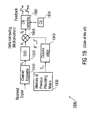
- Fig. 19 shows a conventional receiver structure 1900.
- the conventional receiver 1900 comprises a channel estimator 1910 to which a received signal is provided.
- the receiver 1900 further comprises a memory 1930 where a previous precoding matrix F k-1 is stored.
- Equation 4 shows, that the column adder 1940 adds dummy columns to the previous precoding matrix F k-1 .
- the delta matrix D k is coded column wise. So the first column is taken and an appropriate matching vector is searched in the codebook 1970, upon which the matrix can be reduced by one dimension utilizing a householder function Q n as given in equation 6. With the reduced matrix the next column comprises one dimension less than the first column, thus requiring less feedback. More details on the receiver structure and the mathematical background can be found in R1-060868, Intel, "Performance and complexity of scaleable Precoded MIMO (LLS & SLS),"3GPP RAN1 LTE, Mar 2006.
- Fig. 20 displays a block diagram of a respective transmitter 2000.
- the transmitter 2000 comprises a matrix constructor 2010, which receives the codebook indices m l opt ... m N sopt .
- the matrix constructor 2010 is coupled to codebook 2020 which is the same codebook as used on the receiver side.
- the matrix constructor constructs an estimate D ⁇ k for the respective delta matrix D k from the codebook indices, according to 1 0 0 0 C m 2 ⁇ opt 0 ⁇ ⁇ Q 1 ⁇ d 11 ⁇ d 12 ⁇ d 21 ⁇ d 22 ⁇ d 31 ⁇ d 32 ⁇ d 41 ⁇ d 42 ⁇ ⁇ D ⁇ k .
- P is the Ns x Ns power allocation matrix.
- the Figs. 19 and 20 show a receiver 1900 and a transmitter 2000 of a conventional precoding scheme with tracking capability where the current precoding matrix is updated using the previous one.
- the conventional scheme has the disadvantage that a matrix constructor 2010 is required on the transmitter side in order to form D ⁇ k from the feedback indices. This is owing to the fact that in the conventional scheme multiple indices are fed back due to the use of a vector codebook, where the multiple indices also provide a disadvantage that more feedback bits or a higher feedback data rate is required. Furthermore, the conventional scheme provides the disadvantage that a processing unit 1920 is required in order to carry out a singular value decomposition. The singular value decomposition is a complex mathematical operation, which requires extra processing power on the receiver side. Overall the conventional system has the disadvantage that a high hardware and software complexity is required in order to implement the precoding scheme.
- the object is achieved by a receiver apparatus according to claim 1, a method for providing precoding information according to claim 13, a transmitter apparatus according to claim 15, a method for updating a precoding information according to claim 28, and a transmitted precoding feedback signal according to claim 30.
- a receiver apparatus for providing precoding information comprising a detector for detecting an event and a transmit unit for transmitting absolute precoding information at a first time instant in response to a detected occurrence of the event and for transmitting differential precoding information at a second time instant different from the first time instant.
- a transmitter apparatus for transmitting a signal using precoding for transmitting a signal using precoding, the precoding being updated on a precoding information comprising a detector for detecting an event and a means for updating with an absolute precoding information at a first time instant in response to a detected occurrence of the event and for updating with a differential precoding information at a second time instant different from the first time instant.
- the object is achieved by a method for providing precoding information with a step of detecting an event.
- the method further comprising a step for transmitting absolute precoding information at the first time instant in response to a detected occurrence of the event and for transmitting differential precoding information at a second time instant different from the first time instant.
- the object is further achieved by a method for updating a precoding information comprising a step of detecting an event.
- the method further comprising a step of updating with absolute precoding information at the first time instant in response to a detected occurrence of an event and a step of updating with differential precoding information at a second time instant different from the first time instant.
- the object is further achieved by a transmitted precoding feedback signal having a feedback signal format for performing the above-mentioned method for updating a precoding information when the feedback signal is input into an above-mentioned transmitter apparatus.
- the present invention is based on the finding that a more robust precoding scheme can be established, if differential precoding updates are used if there is significant coherence between two sample points of a mobile radio channel, and absolute precoding updates are used when there is a low coherence between two sample points of a mobile radio channel.
- Embodiments of the present invention provide the advantage, that it is possible to switch between absolute and differential updates enabling an adaptation of the update method in a precoding scheme with e.g. MIMO transmission.
- differential updates are used for small changes of the channel, which can be provided with a higher resolution, whereas absolute updates are used if the channel has changed significantly on a courser resolution.
- Embodiments of the present invention provide the advantage, that a higher channel or system capacity can be achieved with less feedback bits, i.e. with a lower data rate and a feedback channel. Therewith valuable transmission resources can be conserved while a wider range of radio channel changes can be covered.
- Fig. 1 shows an embodiment of a receiver apparatus 100.
- the receiver apparatus 100 is comprised of channel estimator 110, which is coupled with a processing unit 120.
- the processing unit 120 is coupled with a codebook 122, a precoding matrix memory 124 and a searcher 130.
- the searcher 130 is coupled with a transmit unit 140.
- the receiver apparatus 100 is adapted for controlling a precoding operation in a transmitter within a transmission scheme having a first number of transmit antennas and a second number of receive antennas, the first number being larger than one and the second number being larger or equal to one.
- the receiver apparatus 100 comprises the channel estimator 110 for estimating a radio channel between the transmitter and the receiver apparatus 100 based on a received signal to determine a radio channel estimate.
- the receiver apparatus 100 further comprises the processing unit 120 providing possible new matrices based on update information items stored in an update codebook and an old precoding matrix. stored in the precoding matrix memory 124, an update matrix may or may not have at least two rows and at least two columns.
- the receiver apparatus 100 further comprises the searcher 130 for searching a new precoding matrix fulfilling an optimization criteria based on the radio channel estimate among the possible new precoding matrices and a transmit unit 140 for transmitting an update matrix index, which is associated with the new precoding matrix found when searching the new precoding matrices.
- the second number of receive antennas is larger than one and a precoding matrix having at least two rows and at least two columns.
- the processing unit may be adapted for providing a new possible precoding matrices by multiplication, the multiplication having an update matrix and the old processing matrix as multiplication partners.
- the receiver apparatus 100 can be adapted for receiving multi-carrier signals and being operative for controlling a precoding operation in each of or a group of carriers in the multi-carrier signals.
- the processing unit 120 is implemented as a multiplier and multiplies the old precoding matrix from the precoding matrix memory 124 with the update matrices from the codebook 122. Once a new precoding matrix is found, the processing unit can update the precoding matrix for the next update iteration.
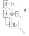
- Fig. 2 shows another embodiment of a receiver apparatus 150.
- the receiver apparatus 150 comprises a channel estimator 155, which evaluates a channel estimate H k from the received signal and provides the channel estimate H k to a codebook searcher 160.
- the receiver further comprises a memory 165 for previous precoding matrices F k-1 , which are multiplied by a multiplier 170 with update matrices C m from a codebook 175, yielding a set of new precoding matrixes C ' m , which is also provided to the codebook searcher 160.
- 1 is an integer smaller than or equal to B
- p is a lower multiplication index greater than or equal to one
- q is a higher multiplication index smaller than or equal to B.
- C' k C k A k F k-1
- the optimisation criterion may be different, for example maximizing a signal-to-noise-ratio or other metrics relating to a quality of a communication link.
- the codebook searcher 160 determines the optimum precoding matrix C' m opt , which can then be provided to the memory 165 of previous precoding matrices as F k for the next iteration of the precoding update. Furthermore, the codebook searcher 160 provides the index of the found optimized update matrix C ' m opt , i.e. m opt to the transmitter.
- the processing unit 120 (Fig. 1) comprises a storage means for storing the codebook, according to the codebook 175.
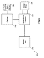
- Fig. 3 shows an embodiment of a transmitter apparatus 200.
- the transmitter apparatus 200 comprises a receive unit 210, a storage means 220, an update matrix generator 230, a combiner 240, and a precoding matrix memory 245.
- the transmitter apparatus 200 is adapted for transmitting a precoded signal, the signal being precoded using a an updated precoding matrix stored in the precoding matrix memory 245 within transmission scheme having a first number of transmit antennas and a second number of receive antennas, the first number being larger than one and the second number being larger or equal to one.
- the transmitter apparatus 200 comprises the receive unit 210 for receiving a received update index and the storage means 220 for storing a codebook having different update information items, each update information item having associated therewith an update index.
- the transmitter apparatus 200 further comprises the update matrix generator 230 for generating an update matrix having at least two rows and at least two columns using the received update index and the associated update information item from the codebook comprised within the storage means 220 and the combiner 240 for combining an earlier used precoding matrix 245 and the update matrix provided by the retriever 230 to obtain the updated precoding matrix.
- the receive unit 210 can be adapted for receiving a received update matrix index (m opt ) and the storage means 220 being adapted for storing a codebook having different update matrices ( C m ), each update matrix ( C m ) having associated therewith an update matrix index (m), an update matrix ( C m ) having at least two rows and at least two columns.
- the combiner 240 is adapted for obtaining the updated precoding matrix ( F k ) by multiplication, the multiplication having the earlier used precoding matrix ( F k-1 ) and the update matrix ( C m opt ) as multiplication partners and the earlier used precoding matrix ( F k-1 ) being multiplied on the right hand side.
- the second number of receive antennas may be larger than one, and a precoding matrix (F k-1 , F k ) can be a square matrix.
- an update matrix ( C m ) may be square matrix.
- the transmitter apparatus 200 may be adapted for transmitting multi-carrier signals and being operative for controlling a precoding operation in each of or a group of carriers in the multi-carrier signals.
- Fig. 4 shows another embodiment of a transmitter apparatus 250.
- the transmitter apparatus 250 comprises a codebook 255, which is provided with the optimum update matrix index m opt , which is received from a receiver. With the received update matrix index, the codebook can provide the associated update matrix C ' m opt .
- the transmitter apparatus 250 further comprises a memory 260 for storing the previous precoding matrix F k - 1 .
- the multiplier 260 can then provide the updated precoding matrix F k .
- the combiner 240 can be implemented as a multiplier 265.
- the transmitter apparatus 200 respectively 250 comprises a precoder for applying the precoding matrix F k to a transmit signal.
- the precoding matrix F k can be initialized in another embodiment, initialization may help to reduce a tracking error in some situations.
- the initialization can be done on a periodical basis or it can be triggered by a control signal or feedback from a receiver.
- the precoding matrix is updated by multiplying the previous precoding matrix to C' m opt from the right hand side. This eliminates the need for a column adder for a matrix size adjustment and the need for a singular value decomposition. Furthermore, the use of a matrix codebook instead of a vector codebook as in a conventional scheme eliminates the need for a matrix constructor, and in addition reduces the required feedback information. Therefore, embodiments provide the advantage that they reduce the hardware and software complexity in a transmitter and in a receiver. Furthermore, the required feedback information is less than in the conventional scheme, therefore requiring less feedback bits , data rate, and transmission resources in the feedback channel.
- Fig. 5 shows a MIMO transmission system 300, comprising an embodiment of a receiver apparatus 310.
- the receiver apparatus 310 comprises a number N r of receive antennas 312 being coupled to a receive unit 314.
- the receive unit 314 provides a received signal to a channel estimator 316 and to an MMSE-SIC detector and decoder 318.
- the channel estimator 316 then provides a channel estimate to the MMSE-SIC detector and decoder 318 and to a codebook searcher 320, which is coupled to a multiplier 322 from which it is provided with the result of the multiplication of a previous precoding matrix F k-1 stored in a storage means 324 and update matrices from a codebook 326, similar to what was described above.
- the codebook searcher 320 provides the optimum update matrix index m opt to a transmitter apparatus 350.
- the MIMO system can also be a generalized MIMO system having a single receive antenna and two or more transmit antenna.
- the first and the second number are such that a precoding matrix F k , F k-1 has more rows than columns.
- the transmitter apparatus 350 comprises a codebook 352, which receives the optimum update matrix index m opt from the receiver apparatus 310.
- the codebook 352 can then provide the optimum update matrix to a multiplier 354.
- the multiplier 354 further receives the previous precoding matrix F k-1 from a previous precoding matrix storage 356.
- An encoder and symbol mapper 358 provides a transmit signal to the multiplier 354, which multiplies the transmit signal with the updated precoding matrix and provides the result to a transmit unit 360.
- the transmit unit 360 utilizes a number N r of transmit antennas 362 to transmit the signal through the radio channel to the receiver apparatus 310.
- the codebook searcher 320 can evaluate the optimum update matrix, e.g. by optimizing a link or system capacity, which can be calculated assuming MMSE-SIC detection, and therefore in one embodiment the codebook searcher 320 and the MMSE-SIC detector and decoder 318 can partially share circuits, which leads to a further reduction of the hardware and software complexity.
- each of the codebook matrices is a unitary matrix, which will be further detailed below.
- the transmitter and the receiver should share the same codebook.
- the codebook can be generated offline and stored in a storage medium or memory in a transmitter as well as in a receiver.
- each element of the considered codebooks C k is an N t x N t matrix. Additionally, as described above, a tracking precoding scheme is assumed, so the codebook should be generated to have tracking capability.
- Fig. 6 shows an embodiment of a codebook generator apparatus 400, which comprises a generator 405 and a combiner 410.
- the embodiment of the codebook generator apparatus 400 is adapted for generating a codebook comprising one or more update matrices to be used in a precoding scheme with a transmission scheme having a first number of transmit antennas and a second number of receive antennas, the first number being larger than one and the second number being larger or equal to one, calculating each update matrix, comprising a generator (405) for generating a first matrix and for generating a second matrix being correlated with the first matrix by a correlation degree and comprising a combiner (410) for combining the first matrix and the second matrix to obtain one update matrix.
- the codebook generator apparatus 400 can generate a codebook having at least two update matrices to be used in a precoding operation, each update matrix being associated with an update matrix index the update matrices being calculated by generating a first matrix and by generating a second matrix being correlated with the first matrix by a correlation degree and by combining the first matrix and the second matrix to obtain one update matrix, where for calculating different update matrices, a different correlation degree or a different first matrix and the same correlation degree is used.
- the generator 405 is adapted for generating matrices with column vectors having a magnitude between 0.5 and 1.5 and with angles between any two column vectors being between 45° and 145°.
- the generator 405 is adapted for generating unitary matrices, matrices which have orthogonal columns, or matrices which are close to orthogonal, which can for example be based on random or pseudo-random matrices.
- each of the update matrices has an associated unique update matrix index.
- the combined update matrix has elements on its diagonal, whose magnitudes are at least twice as high as a magnitude of any off-diagonal element.
- the correlation degree between the first and the second matrix can for example be realized by a generator having a coherence time, i.e. the correlation degree corresponding to a time shift between two generated matrices.
- the correlation degree can further be associated with the fading property of a radio channel.
- a larger codebook matrices with a number of different correlation degrees are considered for generating the update matrices.
- the first and second matrices can be generated using a Jakes model.
- the generator 405 can be adapted for generating the first and second matrices by generating random matrices to which a singular value decomposition is applied or any matrix triangularization method, in order to obtain unitary matrices.
- the unitary matrices may then be multiplied to each other in order to create an update matrix also being unitary, which has tracking capability.
- the codebook as described above may be stored on a storage medium. When using matrix codebooks, it is preferable that each element matrix of the codebook is a unitary matrix, which has orthogonal columns leading to a better performance and lower complexity.
- Fig. 7 shows an embodiment of a codebook generation method.
- a first unitary matrix V (t) is generated by a random unitary matrix generator based on a given time shift ⁇ t.
- each element of the codebook is generated by multiplying two random unitary matrices. Therefore, the resulting matrix is also unitary. Additionally, the two unitary matrices are time shifted versions from each other, i.e. for as long as the generator has a coherence time, they are correlated accordingly, so the resulting codebook element has a tracking capability. More specifically, also referring to equation 16, when a channel variation between two sample periods, i.e. between two feedback periods, is small, the off-diagonal elements ⁇ ij of C m are small compared to the diagonal elements g ii .
- Such a matrix is for finer precoding matrix adjustment. If the channel variation between two sampled periods is large, for example due to fast fading in the radio channel, the off-diagonal elements ⁇ ij should be as large as the diagonal elements g ii to enable a more dynamic precoding matrix adjustment. Therefore, when the codebook is designed in such a way that each element matrix is generated from various ⁇ t, update matrices can be generated for various channel environments. Therefore, embodiments provide the advantage that the codebook can be adapted to various environments based on the time shift ⁇ t, respectively based on the correlation degree.
- Fig. 8a shows a pseudo code of an embodiment of a method for generating an according codebook.
- B is the codebook size and accordingly a loop runs over B iterations indicated by the "for"-loop in steps 450 and 460.
- a step 451 two matrices of size N t x N t are generated, which are time shifted by ⁇ t.
- a step 452 singular value decompositions of both matrices are calculated, and in a step 453 two obtained unitary matrices from step 452 are multiplied in order to obtain one update matrix C m .
- the loop then runs over B iterations.
- the random matrices generated in step 451 may be generated based on a Jakes model, which is also widely used to generate fading coefficients.
- the singular value decomposition is used to obtain unitary matrices.
- each element of the codebook is computed.
- the process of Fig. 8a can be repeated for a sufficient number of times in order to obtain an optimum set of codebooks or update matrices in terms of achievable channel capacities depending on the environment.
- the combiner (410) is adapted for using only a subset of a combination of the first and the second matrices for generating an update matrix and in yet another embodiment the subset corresponds to a row or column vector.
- the codebook generator apparatus (400) may have the generator being adapted for generating the first and second matrices in order to optimize a channel capacity by several trials.
- the codebook generator apparatus (400) can further comprising a means for quantizing the update matrices.
- the matrices which are generated as part of the pseudocode in Fig. 8a can have propagation channel properties. In one embodiment they may be generated as mutually random independent identically distributed variables, i.e. the correlation degree can also be zero. In another embodiment they can be generated as mutually correlated random variables, where the correlation value or degree can be adjusted. In yet another embodiment a range of different correlation values is covered. There may also exist an imbalance among the average power of each of the components, i.e. ⁇ q 11 ⁇ 2 ⁇ q 22 ⁇ 2 . If the codebook gets generated considering the characteristics of the actual propagation channel, such as correlation between antennas and average power imbalance among antennas or propagation paths, the link or system capacity can even further be increased. Furthermore the codebook may include update matrices, which are close or even identical to an identity matrix, which provides the option of not updating a precoding matrix in some situations, in which it might be more beneficial to not update the precoding matrix.
- Fig. 8b shows a viewgraph of achievable capacity improvements with an embodiment.
- Fig. 8b shows two link capacity graphs versus an average signal-to-noise-ratio (SNR). The figure at the top is achieved with the embodiment, the figure at the bottom with the conventional scheme.
- the embodiment provides a capacity improvement of about 0.3b/(s Hz).
- Codebook based precoding with tracking capability exploits the channel coherence between two sample points, i.e. the coherence of one feedback period, and thus offers higher capacity then one-shot codebook based precoding.
- a reliable precoding matrix can sometimes be difficult. Therefore, instead of providing differential update information, as in the case of codebook based precoding with tracking capability, it can in some situations be beneficial to provide absolute precoding information, as in the case of one-shot codebook based precoding.
- Fig. 9 shows a receiver apparatus 700 comprising a detector 710 and a transmit unit 720.
- the receiver apparatus 700 is adapted for providing precoding information, comprising a detector 710 for detecting an event and a transmit unit 720 for transmitting absolute precoding information at a first time instant in response to a detected occurrence of the event and for transmitting differential precoding information at a second time instant different from the first time instant.
- the detector 710 is adapted for detecting as the event a lapse of a predefined period since an earlier time instant, at which the absolute precoding information was sent or, as the event, a situation in which the absolute precoding information is more advantageous for a communication link than the differential precoding information.
- Fig. 10 shows another embodiment of a receiver apparatus 750.
- the receiver apparatus 750 comprises a channel estimator 755 for providing a channel estimate to a codebook searcher 760, which is adapted for searching a one-shot codebook, the channel estimator 755 further providing the channel estimate to another codebook searcher 765, which is adapted for searching in a tracking capable codebook.
- the codebook searcher 765 and the codebook searcher 760 access the same codebook 770. In another embodiment they may have separated codebooks.
- the receiver apparatus 750 further comprises a memory unit 775, which provides the codebook searcher 765 with tracking capability with the previous precoding matrix in order to enable a codebook search as described above.
- the embodiment depicted in Fig. 10 comprises a switch 780, which indicates that the embodiment can either transmit precoding information based on a one-shot codebook, i.e. absolute precoding information, respectively can transmit tracking capable update information being based on a codebook with tracking capability, i.e. differential precoding information.
- a switch 780 which indicates that the embodiment can either transmit precoding information based on a one-shot codebook, i.e. absolute precoding information, respectively can transmit tracking capable update information being based on a codebook with tracking capability, i.e. differential precoding information.
- the receiver apparatus 700 respectively the detector 710 is adapted for detecting the situation in which the absolute precoding information is more advantageous based on a range of the absolute precoding information and the range of the differential precoding information.
- differential precoding information is provided for tracking small changes in the radio channel.
- the codebook is not able to track faster changes in the radio channel as for example evoked by excessive fast fading, high mobility or Doppler-scenarios.
- the detector 710 may decide on transmitting absolute precoding information.
- the transmit unit 720 is adapted for transmitting an indicator indicating whether currently transmitted precoding information is absolute or differential. This indicator can be implemented by a single bit to be transmitted within a feedback or control channel, indicating how the contained control information shall be interpreted.
- the receiver apparatus may be adapted for receiving multi-carrier signals and be operative for providing precoding information operation of each of or a group of carriers in the multi-carrier signals.
- the receiver apparatus (700) can e.g. provide precoding information in terms of a matrix codebook index.
- the receiver apparatus (700) may provide differential precoding information on the basis of a matrix codebook, the matrix codebook having a special codebook index for absolute precoding information, the absolute precoding information being provided on the basis of a column vector of an absolute precoding matrix.
- Fig. 11 shows an embodiment of a transmitter apparatus 800.
- the transmitter apparatus 800 is adapted for transmitting a signal using precoding, the precoding being updated on a precoding information, comprising a detector 810 for detecting an event and a means for updating 820 with absolute precoding information at a first time instant in response to a detected occurrence of the event and for updating with differential precoding information at a second time instant different from the first time instant.
- the detector 810 is adapted for detecting as the event, a lapse of a defined period since an earlier time instant at which the absolute precoding information was received or, as the event, a situation in which the absolute precoding information is more advantageous for a communication link than the differential precoding information.
- the transmitter apparatus 800 further comprises a receiver for receiving the absolute precoding information or the differential precoding information.
- the receiver is adapted for providing an indicator whether the situation in which the absolute precoding information is more advantageous than the differential precoding information has occurred.
- the transmitter apparatus may be able to judge the situation by estimating a radio channel itself.
- Fig. 12 shows another embodiment of a transmitter apparatus 850.
- the transmitter apparatus 850 comprises a memory 855 for storing a previous precoding matrix F k-1 , which is provided to a precoding matrix codebook searcher with tracking capability 860.
- the transmitter apparatus 850 further comprises a precoding matrix searcher 865 for one-shot-mode 865, which has a common codebook 870 with the precoding matrix codebook searcher 860 for tracking mode.
- the transmitter apparatus 850 further comprises a switch 875, which can switch between precoding based on tracking, i.e. based on differential precoding information or precoding based on one-shot updates, i.e. precoding based on absolute precoding information.
- separate codebooks are available for absolute and differential precoding information.
- the transmitter apparatus (800) may in one embodiment be adapted for transmitting multi-carrier signals and being operative for precoding each of or a group of carriers in the multi-carrier signals with differential or absolute precoding information.
- the transmitter apparatus (800) can precode on a basis of a matrix codebook index and the matrix codebook may have a special codebook index for absolute precoding information, the absolute precoding information being provided on the basis of a column vector of an absolute precoding matrix.
- the embodiments described above provide a mechanism to switch between tracking and one-shot codebook mode to combat the situation where sudden channel changes or feedback errors occur.
- the precoding matrix generation at the transmitter apparatus and the codebook search are performed either in tracking or in one-shot codebook mode.
- one codebook is shared between the two modes, and in yet another separate codebooks are used.
- the switching between the two modes can for example in one embodiment be done in a periodical manner according to a predetermined period known to the transmitter and the receiver. In another embodiment switching can be done based on the feedback from the receiver, e.g. by an indicator used within the feedback.
- Fig. 13 shows a table with 4 cells, where the cells on the left hand side refer to the transmitter, the cells on the right hand side refer to the receiver, the cells at the top refer to one-shot mode, and the cells at the bottom refer to tracking mode.
- one-shot mode it is preferable to use a column vector index as a precoding vector, as is described in detail in R1-050903, Qualcomm, Europe, "Description and link simulations of MIMO schemes for OFDMA based E-UTRA downlink evaluation".
- column vectors are chosen from a codebook and used as precoding matrix.
- N t the number of transmit antennas
- column vectors are chosen accordingly, for example for maximizing a channel capacity as indicated in Fig. 13.
- the preferable column subset is then signaled to the transmitter.
- the transmitter applies a signaled update matrix to the previous precoding matrix according to the description above.
- the receiver evaluates an optimized update matrix index according to what was described above and feedbacks it to the transmitter.
- the initial precoding matrix which is determined in one-shot mode, can be set using one-shot mode. From there it can be updated using tracking mode.
- Fig. 14 shows an embodiment of a signaling scheme. It is supposed that a signaling word comprises a number of digits according to the signaling word 1400.
- the signaling word 1400 comprises an indicator at its first digit, indicating whether tracking or one-shot mode is used.
- the other digits refer to a codebook index in case of tracking mode, respectively, to a column subset of a matrix in one-shot mode.
- N t 4
- the two sample code words 1410 and 1420 may result.
- the sample signaling word 1410 has a one in its first digit, indicating one-shot note.
- the potential transmitter would know that the last digits refer to a column subset index C 1 . If the signaling word 1420 is received, the transmitter would know by the first digit being equal to zero that tracking mode is used. The last 4 digits of the signaling word then refer to a codebook index for example for the codebook C 2 to C 17 .
- the first bit of the 5-bit index is the indicating bit if tracking or one-shot mode is used.
- the other bits respectively are column subscript indices in the one-shot case, and codebook indices in the tracking case. In this way, the same feedback bits can be used for both modes.
- the first bit x in Fig. 14 is not necessary and can be omitted.
- OFDM orthogonal frequency division multiplexing
- Fig. 15 shows a viewgraph illustrating the achievable capacity improvements with an embodiment.
- Fig. 15 shows two capacity figures in b/(s Hz) versus an average SNR of the embodiment and the conventional scheme in one-shot mode only.
- the conventional scheme only uses one-shot mode, contrary hereto the embodiment can utilize the above-mentioned switching mechanism.
- the capacity achieved with the embodiment is shown at the top, the capacity achieved with the conventional concept is shown at the bottom of Fig. 15. It can be seen that the embodiment achieves about 0.5 b/(s Hz) capacity gain, using one extra bit as mode indicator.
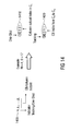
- Fig. 16a shows a viewgraph of an evaluated link capacity in b/(s Hz) versus a number of feedback bits.
- the viewgraph shows the conventional scheme indicated by circles and the embodiment using crosses. It can be seen that the embodiments achieve a higher capacity independent of the number of feedback bits used. It is therefore an advantage of the embodiments that they provide a higher link and system capacity.
- Fig. 16b shows another viewgraph, showing a link capacity in b/(s Hz) versus an average SNR.
- the viewgraph shows three capacity diagrams one of the proposed approach indicated by crosses, one of the conventional approach indicated by circles, and one of the theoretical upper bound (Shannon bound).
- the viewgraph shows that the capacity of the proposed approach is closer to the upper bound than the conventional approach.
- Embodiments therefore provide the advantage that the capacity of a link or system is higher than for the conventional approach.
- embodiments provide the advantage that a higher capacity can be achieved in MIMO transmission systems using precoding. Furthermore, less feedback is required for embodiments than for conventional approaches. Therewith, the spectral efficiency of MIMO-systems can be improved, extra capacity due to the reduced feedback can be utilized.
- the inventive methods can be implemented in hardware or in software.
- the implementation can be performed using a digital storage medium, in particular a disc, DVD or a CD having electronically readable control signals stored thereon, which cooperate with a programmable computer system such that the inventive methods are performed.
- the present invention is therefore a machine readable carrier, the program code being operative for performing the inventive methods when the computer program products runs on a computer.
- the inventive methods are, therefore, a computer program having a program code for performing at least one to the inventive methods when the computer program runs on a computer.
Landscapes
- Engineering & Computer Science (AREA)
- Computer Networks & Wireless Communication (AREA)
- Signal Processing (AREA)
- Physics & Mathematics (AREA)
- Mathematical Physics (AREA)
- Power Engineering (AREA)
- Radio Transmission System (AREA)
Abstract
Description
- The present invention is in the field of multiple-input-multiple-output (MIMO) transmission as it is more and more used in mobile communication scenarios and as considered for future mobile communication systems.
- MIMO-systems in general can significantly improve system capacity of mobile communication systems. This is for example achieved as MIMO-systems can simultaneously transmit and receive multiple data streams using multiple transmit and receive antennas. Fig. 17 shows a general MIMO-system 1700. The scenario shows a transmit
unit 1710 utilizing Nt transmitantennas 1712. The signals transmitted by thetransmit antennas 1712 are received by areceiver unit 1720 utilizing Nr receiveantennas 1722. Between thetransmit antennas 1712 and the receiveantennas 1722 there is a mobile radio channel, which is labeled with k in Fig. 17. The signals which are transmitted by thetransmit unit 1710 are labeled x k and are precoded by aprecoding unit 1730. Theprecoding unit 1730 applies a precoding matrix F k to the actual data streams s k which are to be transmitted. - The precoding matrix Fk is based on a feedback received from the receiver side, which preferably uses a codebook in order to feed back an index mopt. In the scenario depicted in Fig. 17 these indices are determined from a
codebook 1740, which is available on the transmitter and on the receiver side. The received signals are detected by adetector 1750 on the receiver side, which carries out channel estimation, i.e. the channel H k is estimated, a precoding evaluated based on the channel estimate, coded according to theavailable codebook 1740 and the index of the respective codebook is provided to the transmitter. Fig. 17 therefore shows a MIMO-system with a codebook based precoding scheme. MIMO-precoding schemes can transmit multiple data streams viamultiple beams 1760 and can thus increase the system capacity. - Feeding back complete channel information from the receiver makes it possible to conduct perfect precoding at a transmitter, however this requires high amounts of feedback information, i.e. signaling channels from the receiver to the transmitter, which utilize high data rates for detailed feedback information. Therefore, the reduction of the amount of the feedback is a major challenge in the field of MIMO-systems with codebook based precoding. Codebook based linear precoding requires only transmission of the preferable index of the predetermined codebook set as feedback information and requires therewith less feedback information.
- Referring to Fig. 17, where the numbers of transmit and receive antennas are Nt and Nr, and the number of simultaneously transmitted streams is Ns, the transmitted signal vector at time k can be written as

where the precoding matrix F k is computed from the elements of the codebook. Inequation 1 the MIMO-channel H k can be defined as
- Design concepts of codebooks are classified either as "one-shot codebook" or "tracking codebook". The main difference between the two codebook design concepts are described in the following Table 1.
Table 1: Type Description One-shot CB A current precoding matrix is independent of the previous one. Tracking CB A current precoding matrix depends on the previous one. - In case of one-shot codebooks each element of the codebook can be matrix or vector. The former is called matrix codebook and the latter is called vector codebook. In case of tracking codebooks conventional systems use vector codebooks with mostly recursive transmission algorithms as further detailed below.
- Fig. 18 shows a viewgraph of a channel coefficient of a mobile radio channel over a time axis. It is supposed that feedback is provided and channel samples taken in equidistant time periods, indicated in Fig. 18 by black dots. From the sampling points in Fig. 18 it can be seen that between two channel estimates and feedback periods the channel changes by a certain degree, which depends e.g. on the mobility within the communication scenario. In dependence on this change, the design concept of a codebook is chosen. If the channel changes are small, then the channel can be tracked, and a tracking codebook would be preferable. If the changes are rather high, then the one-shot codebook is preferable. In a practical wireless communication scenario, channels between two sample points can be correlated due to e.g. slow fading or a fast sampling frequency, which can be equivalent to a short feedback period. In this case a tracking codebook can offer a better trade-off between performance and required feedback bits, i.e. the required data rate on the feedback channel.
- In the following an example system will be considered utilizing Nt=4 transmit antennas, Nr=2 receive antennas, and Ns=2 data streams. Furthermore throughout this description k denotes a time index. Fig. 19 shows a
conventional receiver structure 1900. Theconventional receiver 1900 comprises achannel estimator 1910 to which a received signal is provided. Thechannel estimator 1910 estimates the radio channel on the basis of reference symbols and provides a channel estimate Hk to aprocessing unit 1920, which carries out a singular value decomposition, yielding a unitary matrix V k, according to
- The
receiver 1900 further comprises amemory 1930 where a previous precoding matrix F k-1 is stored. - The
receiver 1900 further comprises acolumn adder 1940 for adding a column to the previous precoding matrix F k-1 yielding (F' k-1)H, according to
-
Equation 4 shows, that thecolumn adder 1940 adds dummy columns to the previous precoding matrix Fk-1. In order to compute a delta matrix the outcome of thecolumn adder 1940 and theprocessing unit 1920 are multiplied in amultiplier 1950, which delivers a delta matrix D k, which in turn is input into acodebook searcher 1960, according to
- The
codebook searcher 1960 uses acodebook 1970 to encode the delta matrix D k and deliversindices 
vector codebook 1970, according to
- As can be seen from
equation 6 the delta matrix D k is coded column wise. So the first column is taken and an appropriate matching vector is searched in thecodebook 1970, upon which the matrix can be reduced by one dimension utilizing a householder function Q n as given inequation 6. With the reduced matrix the next column comprises one dimension less than the first column, thus requiring less feedback. More details on the receiver structure and the mathematical background can be found in R1-060868, Intel, "Performance and complexity of scaleable Precoded MIMO (LLS & SLS),"3GPP RAN1 LTE, Mar 2006. - Fig. 20 displays a block diagram of a
respective transmitter 2000. Thetransmitter 2000 comprises amatrix constructor 2010, which receives the codebook indices m l opt ...mNsopt . Thematrix constructor 2010 is coupled tocodebook 2020 which is the same codebook as used on the receiver side. Using a recursive algorithm, the matrix constructor constructs an estimate D̃ k for the respective delta matrix D k from the codebook indices, according to
- The
transmitter 2000 further comprises amemory 2030 with the stored previous precoding matrix F k-1 to which acolumn adder 2040 adds dummy columns according to
- A
multiplier 2050 then multiplies the column added previous precoding matrix and the estimated delta matrix to obtain a new precoding matrix, which can then be applied to the data streams s in order to obtain the transmit signals x, according to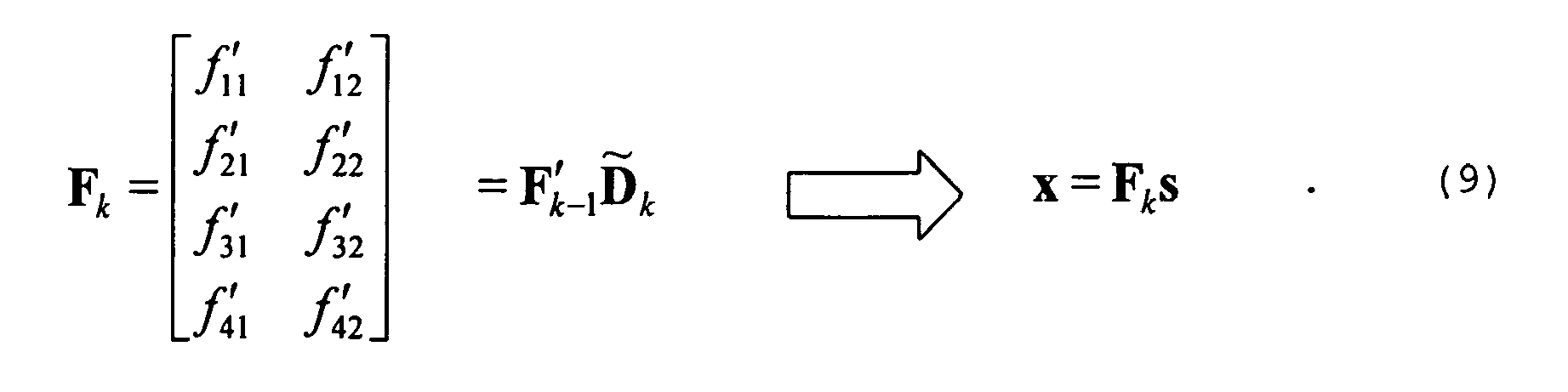
- Alternatively, the above equation can also be amended as follows:
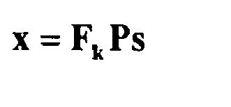
- In this equation, P is the Ns x Ns power allocation matrix.
- The
conventional transmitter 2000 and theconventional receiver 1900 use thesame codebooks 2020 respectively 1970, which is comprised of vectors of a different length, performing the recursive delta matrix coding algorithm.Equation 10 describes a codebook CB in more detail,
- More details on the transmitter structure and the mathematical background can be found in R1-060868, Intel, "Performance and complexity of scaleable precoded MIMO (LLS & SLS)", 3GPP RAN1 LTE, Mar 2006.
- The Figs. 19 and 20 show a
receiver 1900 and atransmitter 2000 of a conventional precoding scheme with tracking capability where the current precoding matrix is updated using the previous one. The conventional scheme has the disadvantage that a column adder is required in order to adjust the size of the matrices. This is due to the fact that a precoding matrix is updated by multiplying the previous precoding matrix from the left hand side according to
- The number of added columns or dummy columns depends on the number of transmitted data streams. Moreover, the conventional scheme has the disadvantage that a
matrix constructor 2010 is required on the transmitter side in order to form D̃ k from the feedback indices. This is owing to the fact that in the conventional scheme multiple indices are fed back due to the use of a vector codebook, where the multiple indices also provide a disadvantage that more feedback bits or a higher feedback data rate is required. Furthermore, the conventional scheme provides the disadvantage that aprocessing unit 1920 is required in order to carry out a singular value decomposition. The singular value decomposition is a complex mathematical operation, which requires extra processing power on the receiver side. Overall the conventional system has the disadvantage that a high hardware and software complexity is required in order to implement the precoding scheme. - It is the object of the present invention to provide a more robust scheme for providing precoding information in a mobile communication system.
- The object is achieved by a receiver apparatus according to
claim 1, a method for providing precoding information according to claim 13, a transmitter apparatus according to claim 15, a method for updating a precoding information according to claim 28, and a transmitted precoding feedback signal according to claim 30. - The object is achieved by a receiver apparatus for providing precoding information comprising a detector for detecting an event and a transmit unit for transmitting absolute precoding information at a first time instant in response to a detected occurrence of the event and for transmitting differential precoding information at a second time instant different from the first time instant.
- The object is achieved by a transmitter apparatus for transmitting a signal using precoding, the precoding being updated on a precoding information comprising a detector for detecting an event and a means for updating with an absolute precoding information at a first time instant in response to a detected occurrence of the event and for updating with a differential precoding information at a second time instant different from the first time instant.
- The object is achieved by a method for providing precoding information with a step of detecting an event. The method further comprising a step for transmitting absolute precoding information at the first time instant in response to a detected occurrence of the event and for transmitting differential precoding information at a second time instant different from the first time instant.
- The object is further achieved by a method for updating a precoding information comprising a step of detecting an event. The method further comprising a step of updating with absolute precoding information at the first time instant in response to a detected occurrence of an event and a step of updating with differential precoding information at a second time instant different from the first time instant.
- The object is further achieved by a transmitted precoding feedback signal having a feedback signal format for performing the above-mentioned method for updating a precoding information when the feedback signal is input into an above-mentioned transmitter apparatus.
- The present invention is based on the finding that a more robust precoding scheme can be established, if differential precoding updates are used if there is significant coherence between two sample points of a mobile radio channel, and absolute precoding updates are used when there is a low coherence between two sample points of a mobile radio channel. Embodiments of the present invention provide the advantage, that it is possible to switch between absolute and differential updates enabling an adaptation of the update method in a precoding scheme with e.g. MIMO transmission.
- In one embodiment differential updates are used for small changes of the channel, which can be provided with a higher resolution, whereas absolute updates are used if the channel has changed significantly on a courser resolution.
- Embodiments of the present invention provide the advantage, that a higher channel or system capacity can be achieved with less feedback bits, i.e. with a lower data rate and a feedback channel. Therewith valuable transmission resources can be conserved while a wider range of radio channel changes can be covered.
- Embodiments of the present invention will be detailed using the figures attached, in which
- Fig. 1
- shows an embodiment of a receiver apparatus;
- Fig. 2
- shows another embodiment of a receiver apparatus;
- Fig. 3
- shows an embodiment of a transmitter apparatus;
- Fig. 4
- shows another embodiment of a transmitter apparatus;
- Fig. 5
- shows an embodiment of a MIMO transmission system;
- Fig. 6
- shows an embodiment of a codebook generator apparatus;
- Fig. 7
- shows an embodiment of a method for generating a plurality of update matrices;
- Fig. 8a
- shows a pseudo code of an embodiment of a method for generating a plurality of update matrices;
- Fig. 8b
- shows a viewgraph illustrating achievable capacity improvements with a respective embodiment.
- Fig. 9
- shows another embodiment of a receiver apparatus;
- Fig. 10
- shows another embodiment of a receiver apparatus;
- Fig. 11
- shows another embodiment of a transmitter apparatus;
- Fig. 12
- shows another embodiment of a transmitter apparatus;
- Fig. 13
- shows an embodiment of a method for updating precoding information with absolute and differential precoding update information;
- Fig. 14
- shows an embodiment of a method for providing precoding information;
- Fig. 15
- shows a viewgraph illustrating achievable capacity improvements with a respective embodiment;
- Fig. 16a
- shows simulation results illustrating the capacity improvements of respective embodiments;
- Fig. 16b
- shows simulation results illustrating the capacity improvements over an average signal-to-noise-ratio achievable with respective embodiments.
- Fig. 1 shows an embodiment of a
receiver apparatus 100. Thereceiver apparatus 100 is comprised ofchannel estimator 110, which is coupled with aprocessing unit 120. Theprocessing unit 120 is coupled with acodebook 122, aprecoding matrix memory 124 and asearcher 130. Thesearcher 130 is coupled with a transmitunit 140. Thereceiver apparatus 100 is adapted for controlling a precoding operation in a transmitter within a transmission scheme having a first number of transmit antennas and a second number of receive antennas, the first number being larger than one and the second number being larger or equal to one. Thereceiver apparatus 100 comprises thechannel estimator 110 for estimating a radio channel between the transmitter and thereceiver apparatus 100 based on a received signal to determine a radio channel estimate. - The
receiver apparatus 100 further comprises theprocessing unit 120 providing possible new matrices based on update information items stored in an update codebook and an old precoding matrix. stored in theprecoding matrix memory 124, an update matrix may or may not have at least two rows and at least two columns. Thereceiver apparatus 100 further comprises thesearcher 130 for searching a new precoding matrix fulfilling an optimization criteria based on the radio channel estimate among the possible new precoding matrices and a transmitunit 140 for transmitting an update matrix index, which is associated with the new precoding matrix found when searching the new precoding matrices. - In one embodiment the second number of receive antennas is larger than one and a precoding matrix having at least two rows and at least two columns. The processing unit may be adapted for providing a new possible precoding matrices by multiplication, the multiplication having an update matrix and the old processing matrix as multiplication partners. Moreover, the
receiver apparatus 100 can be adapted for receiving multi-carrier signals and being operative for controlling a precoding operation in each of or a group of carriers in the multi-carrier signals. - In one embodiment the
processing unit 120 is implemented as a multiplier and multiplies the old precoding matrix from theprecoding matrix memory 124 with the update matrices from thecodebook 122. Once a new precoding matrix is found, the processing unit can update the precoding matrix for the next update iteration. - Fig. 2 shows another embodiment of a
receiver apparatus 150. Thereceiver apparatus 150 comprises a channel estimator 155, which evaluates a channel estimate H k from the received signal and provides the channel estimate H k to acodebook searcher 160. The receiver further comprises amemory 165 for previous precoding matrices F k-1, which are multiplied by amultiplier 170 with update matrices C m from acodebook 175, yielding a set of new precoding matrixes C'm, which is also provided to thecodebook searcher 160. The updated precoding matrices are given by
where the previous precoding matrix F k-1 is multiplied on the right hand side in order to determine a set of possible new precoding matrices to be searched. Generally 1 is an integer smaller than or equal to B, p is a lower multiplication index greater than or equal to one and q is a higher multiplication index smaller than or equal to B. Thus, one can also calculate a subset of the indices from 1 to B e.g. 1,2,4,B. In this case p would be 1 and q would be B and there would only be two numbers in between, such as 2,4. - In yet another embodiment another matrix may be multiplied, i.e. C'k= CkAkFk-1, in order to carry out any other precoding or adaptation task. The
codebook searcher 160 carries out a search throughout all updated precoding matrices C'm in order to find an optimized precoding matrix C' mopt , which for example in one embodiment maximizes the channel capacity for the given channel estimate H k, which can be denoted as
wherein σ2 denotes the noise variance or noise power. Note that in other embodiments the optimisation criterion may be different, for example maximizing a signal-to-noise-ratio or other metrics relating to a quality of a communication link. Thecodebook searcher 160 determines the optimum precoding matrix C' mopt , which can then be provided to thememory 165 of previous precoding matrices as F k for the next iteration of the precoding update. Furthermore, thecodebook searcher 160 provides the index of the found optimized update matrix C' mopt , i.e. mopt to the transmitter. - In another embodiment the
codebook searcher 160 determines a maximum capacity on the basis of a minimum-mean-square-error-successive-interference-cancellation detection (MMSE-SIC = minimum-mean-square-error-successive-interference-cancellation). In another embodiment the processing unit 120 (Fig. 1) comprises a storage means for storing the codebook, according to thecodebook 175. - Fig. 3 shows an embodiment of a
transmitter apparatus 200. Thetransmitter apparatus 200 comprises a receiveunit 210, a storage means 220, anupdate matrix generator 230, acombiner 240, and aprecoding matrix memory 245. - The
transmitter apparatus 200 is adapted for transmitting a precoded signal, the signal being precoded using a an updated precoding matrix stored in theprecoding matrix memory 245 within transmission scheme having a first number of transmit antennas and a second number of receive antennas, the first number being larger than one and the second number being larger or equal to one. Thetransmitter apparatus 200 comprises the receiveunit 210 for receiving a received update index and the storage means 220 for storing a codebook having different update information items, each update information item having associated therewith an update index. Thetransmitter apparatus 200 further comprises theupdate matrix generator 230 for generating an update matrix having at least two rows and at least two columns using the received update index and the associated update information item from the codebook comprised within the storage means 220 and thecombiner 240 for combining an earlierused precoding matrix 245 and the update matrix provided by theretriever 230 to obtain the updated precoding matrix. - In one embodiment the receive
unit 210 can be adapted for receiving a received update matrix index (mopt) and the storage means 220 being adapted for storing a codebook having different update matrices (C m), each update matrix (C m) having associated therewith an update matrix index (m), an update matrix (C m) having at least two rows and at least two columns. - In another embodiment the
combiner 240 is adapted for obtaining the updated precoding matrix (F k) by multiplication, the multiplication having the earlier used precoding matrix (F k-1) and the update matrix (C mopt ) as multiplication partners and the earlier used precoding matrix (F k-1) being multiplied on the right hand side. The second number of receive antennas may be larger than one, and a precoding matrix (Fk-1, Fk) can be a square matrix. Moreover, an update matrix (C m) may be square matrix. Thetransmitter apparatus 200 may be adapted for transmitting multi-carrier signals and being operative for controlling a precoding operation in each of or a group of carriers in the multi-carrier signals. - Fig. 4 shows another embodiment of a
transmitter apparatus 250. Thetransmitter apparatus 250 comprises acodebook 255, which is provided with the optimum update matrix index mopt, which is received from a receiver. With the received update matrix index, the codebook can provide the associated update matrix C' mopt . Thetransmitter apparatus 250 further comprises amemory 260 for storing the previous precoding matrix F k-1. Furthermore, thereceiver apparatus 250 comprises amultiplier 265, which multiplies the update matrix with the previous precoding matrix according to
- The
multiplier 260 can then provide the updated precoding matrix F k. According to the embodiment shown in Fig. 4, thecombiner 240 can be implemented as amultiplier 265. In another embodiment, thetransmitter apparatus 200 respectively 250 comprises a precoder for applying the precoding matrix F k to a transmit signal. - Furthermore the precoding matrix F k can be initialized in another embodiment, initialization may help to reduce a tracking error in some situations. The initialization can be done on a periodical basis or it can be triggered by a control signal or feedback from a receiver. The initialization matrix can be one element of the codebook and in an embodiment it can be composed of unit vectors as taken from an identity matrix, e.g. for Nt=4 transmit antennas and Ns=2
data streams 
- Note an essential difference to the conventional scheme is that the precoding matrix is updated by multiplying the previous precoding matrix to C' m
opt from the right hand side. This eliminates the need for a column adder for a matrix size adjustment and the need for a singular value decomposition. Furthermore, the use of a matrix codebook instead of a vector codebook as in a conventional scheme eliminates the need for a matrix constructor, and in addition reduces the required feedback information. Therefore, embodiments provide the advantage that they reduce the hardware and software complexity in a transmitter and in a receiver. Furthermore, the required feedback information is less than in the conventional scheme, therefore requiring less feedback bits , data rate, and transmission resources in the feedback channel. - Fig. 5 shows a
MIMO transmission system 300, comprising an embodiment of areceiver apparatus 310. Thereceiver apparatus 310 comprises a number Nr of receiveantennas 312 being coupled to a receiveunit 314. The receiveunit 314 provides a received signal to achannel estimator 316 and to an MMSE-SIC detector anddecoder 318. Thechannel estimator 316 then provides a channel estimate to the MMSE-SIC detector anddecoder 318 and to acodebook searcher 320, which is coupled to amultiplier 322 from which it is provided with the result of the multiplication of a previous precoding matrix F k-1 stored in a storage means 324 and update matrices from acodebook 326, similar to what was described above. Once having found the optimum update matrix, thecodebook searcher 320 provides the optimum update matrix index mopt to atransmitter apparatus 350. - Generally, the MIMO system can also be a generalized MIMO system having a single receive antenna and two or more transmit antenna. Preferably, the first and the second number are such that a precoding matrix F k, F k-1 has more rows than columns.
- The
transmitter apparatus 350 comprises acodebook 352, which receives the optimum update matrix index mopt from thereceiver apparatus 310. Thecodebook 352 can then provide the optimum update matrix to amultiplier 354. Themultiplier 354 further receives the previous precoding matrix F k-1 from a previousprecoding matrix storage 356. An encoder andsymbol mapper 358 provides a transmit signal to themultiplier 354, which multiplies the transmit signal with the updated precoding matrix and provides the result to a transmitunit 360. The transmitunit 360 utilizes a number Nr of transmitantennas 362 to transmit the signal through the radio channel to thereceiver apparatus 310. - In the embodiment shown in Fig. 5, the
codebook searcher 320 can evaluate the optimum update matrix, e.g. by optimizing a link or system capacity, which can be calculated assuming MMSE-SIC detection, and therefore in one embodiment thecodebook searcher 320 and the MMSE-SIC detector anddecoder 318 can partially share circuits, which leads to a further reduction of the hardware and software complexity. Furthermore, in another embodiment, each of the codebook matrices is a unitary matrix, which will be further detailed below. In embodiments of codebook based precoding systems, the transmitter and the receiver should share the same codebook. The codebook can be generated offline and stored in a storage medium or memory in a transmitter as well as in a receiver. Generally, the generation of a codebook relates to the system performance, therefore is the generation of a codebook critical. According to the embodiments described above, each element of the considered codebooks C k is an Nt x Nt matrix. Additionally, as described above, a tracking precoding scheme is assumed, so the codebook should be generated to have tracking capability. - Fig. 6 shows an embodiment of a
codebook generator apparatus 400, which comprises agenerator 405 and acombiner 410. The embodiment of thecodebook generator apparatus 400 is adapted for generating a codebook comprising one or more update matrices to be used in a precoding scheme with a transmission scheme having a first number of transmit antennas and a second number of receive antennas, the first number being larger than one and the second number being larger or equal to one, calculating each update matrix, comprising a generator (405) for generating a first matrix and for generating a second matrix being correlated with the first matrix by a correlation degree and comprising a combiner (410) for combining the first matrix and the second matrix to obtain one update matrix. - The
codebook generator apparatus 400 can generate a codebook having at least two update matrices to be used in a precoding operation, each update matrix being associated with an update matrix index the update matrices being calculated by generating a first matrix and by generating a second matrix being correlated with the first matrix by a correlation degree and by combining the first matrix and the second matrix to obtain one update matrix, where for calculating different update matrices, a different correlation degree or a different first matrix and the same correlation degree is used. - In one embodiment the
generator 405 is adapted for generating matrices with column vectors having a magnitude between 0.5 and 1.5 and with angles between any two column vectors being between 45° and 145°. In another embodiment thegenerator 405 is adapted for generating unitary matrices, matrices which have orthogonal columns, or matrices which are close to orthogonal, which can for example be based on random or pseudo-random matrices. In another embodiment each of the update matrices has an associated unique update matrix index. In yet another embodiment the combined update matrix has elements on its diagonal, whose magnitudes are at least twice as high as a magnitude of any off-diagonal element. The correlation degree between the first and the second matrix can for example be realized by a generator having a coherence time, i.e. the correlation degree corresponding to a time shift between two generated matrices. The correlation degree can further be associated with the fading property of a radio channel. In an embodiment of a larger codebook matrices with a number of different correlation degrees are considered for generating the update matrices. For example the first and second matrices can be generated using a Jakes model. - In another embodiment of
codebook generator apparatus 400, thegenerator 405 can be adapted for generating the first and second matrices by generating random matrices to which a singular value decomposition is applied or any matrix triangularization method, in order to obtain unitary matrices. The unitary matrices may then be multiplied to each other in order to create an update matrix also being unitary, which has tracking capability. In yet another embodiment the codebook as described above may be stored on a storage medium. When using matrix codebooks, it is preferable that each element matrix of the codebook is a unitary matrix, which has orthogonal columns leading to a better performance and lower complexity. - Fig. 7 shows an embodiment of a codebook generation method. A first unitary matrix V(t) is generated by a random unitary matrix generator based on a given time shift Δt. The two matrices are then multiplied in a
step 440 of which the outcome is a matrix G, according to
yielding one update matrix C m as given inequation 16. According to the embodiment in Fig. 7, each element of the codebook is generated by multiplying two random unitary matrices. Therefore, the resulting matrix is also unitary. Additionally, the two unitary matrices are time shifted versions from each other, i.e. for as long as the generator has a coherence time, they are correlated accordingly, so the resulting codebook element has a tracking capability. More specifically, also referring toequation 16, when a channel variation between two sample periods, i.e. between two feedback periods, is small, the off-diagonal elements εij of C m are small compared to the diagonal elements gii. - Such a matrix is for finer precoding matrix adjustment. If the channel variation between two sampled periods is large, for example due to fast fading in the radio channel, the off-diagonal elements εij should be as large as the diagonal elements gii to enable a more dynamic precoding matrix adjustment. Therefore, when the codebook is designed in such a way that each element matrix is generated from various Δt, update matrices can be generated for various channel environments. Therefore, embodiments provide the advantage that the codebook can be adapted to various environments based on the time shift Δt, respectively based on the correlation degree.
- Fig. 8a shows a pseudo code of an embodiment of a method for generating an according codebook. In the pseudo code, depicted in Fig. 8a B is the codebook size and accordingly a loop runs over B iterations indicated by the "for"-loop in
steps step 451 two matrices of size Nt x Nt are generated, which are time shifted by Δt. In astep 452 singular value decompositions of both matrices are calculated, and in a step 453 two obtained unitary matrices fromstep 452 are multiplied in order to obtain one update matrix C m. The loop then runs over B iterations. The random matrices generated instep 451 may be generated based on a Jakes model, which is also widely used to generate fading coefficients. The singular value decomposition is used to obtain unitary matrices. In step 453, each element of the codebook is computed. Furthermore, the process of Fig. 8a can be repeated for a sufficient number of times in order to obtain an optimum set of codebooks or update matrices in terms of achievable channel capacities depending on the environment. - In another embodiment a subset of the matrix G could be defined as

i.e. a subset e.g. a row or column vector of V(t)V(t+Δt) H is used to generate an update matrix for the codebook. In one embodiment the combiner (410) is adapted for using only a subset of a combination of the first and the second matrices for generating an update matrix and in yet another embodiment the subset corresponds to a row or column vector. - The codebook generator apparatus (400) may have the generator being adapted for generating the first and second matrices in order to optimize a channel capacity by several trials. The codebook generator apparatus (400) can further comprising a means for quantizing the update matrices. The update matrices may be square matrices in another embodiment. Alternatively, they can be symmetric or conjugate symmetric matrices as e.g. expressed by (A^T=A, A^H=A) .
- The matrices , which are generated as part of the pseudocode in Fig. 8a can have propagation channel properties. In one embodiment they may be generated as mutually random independent identically distributed variables, i.e. the correlation degree can also be zero. In another embodiment they can be generated as mutually correlated random variables, where the correlation value or degree can be adjusted. In yet another embodiment a range of different correlation values is covered. There may also exist an imbalance among the average power of each of the components, i.e. ∥q 11∥2≠∥q 22∥2. If the codebook gets generated considering the characteristics of the actual propagation channel, such as correlation between antennas and average power imbalance among antennas or propagation paths, the link or system capacity can even further be increased. Furthermore the codebook may include update matrices, which are close or even identical to an identity matrix, which provides the option of not updating a precoding matrix in some situations, in which it might be more beneficial to not update the precoding matrix.
- Fig. 8b shows a viewgraph of achievable capacity improvements with an embodiment. Fig. 8b shows two link capacity graphs versus an average signal-to-noise-ratio (SNR). The figure at the top is achieved with the embodiment, the figure at the bottom with the conventional scheme. An exemplified scenario with a number Nt=4 of transmit antennas, a number Nr=2 receive antennas, and a number Ns=2 of data streams is considered. The embodiment provides a capacity improvement of about 0.3b/(s Hz).
- Codebook based precoding with tracking capability exploits the channel coherence between two sample points, i.e. the coherence of one feedback period, and thus offers higher capacity then one-shot codebook based precoding. However, if feedback errors occur or sudden changes in the propagation channel occurs, tracking of a reliable precoding matrix can sometimes be difficult. Therefore, instead of providing differential update information, as in the case of codebook based precoding with tracking capability, it can in some situations be beneficial to provide absolute precoding information, as in the case of one-shot codebook based precoding. Fig. 9 shows a
receiver apparatus 700 comprising adetector 710 and a transmitunit 720. Thereceiver apparatus 700 is adapted for providing precoding information, comprising adetector 710 for detecting an event and a transmitunit 720 for transmitting absolute precoding information at a first time instant in response to a detected occurrence of the event and for transmitting differential precoding information at a second time instant different from the first time instant. - In an embodiment, the
detector 710 is adapted for detecting as the event a lapse of a predefined period since an earlier time instant, at which the absolute precoding information was sent or, as the event, a situation in which the absolute precoding information is more advantageous for a communication link than the differential precoding information. - Fig. 10 shows another embodiment of a
receiver apparatus 750. Thereceiver apparatus 750 comprises achannel estimator 755 for providing a channel estimate to acodebook searcher 760, which is adapted for searching a one-shot codebook, thechannel estimator 755 further providing the channel estimate to anothercodebook searcher 765, which is adapted for searching in a tracking capable codebook. In the embodiment of thereceiver apparatus 750 depicted in Fig. 10 thecodebook searcher 765 and thecodebook searcher 760 access thesame codebook 770. In another embodiment they may have separated codebooks. Thereceiver apparatus 750 further comprises amemory unit 775, which provides thecodebook searcher 765 with tracking capability with the previous precoding matrix in order to enable a codebook search as described above. Furthermore, the embodiment depicted in Fig. 10 comprises aswitch 780, which indicates that the embodiment can either transmit precoding information based on a one-shot codebook, i.e. absolute precoding information, respectively can transmit tracking capable update information being based on a codebook with tracking capability, i.e. differential precoding information. - In another embodiment the
receiver apparatus 700 respectively thedetector 710 is adapted for detecting the situation in which the absolute precoding information is more advantageous based on a range of the absolute precoding information and the range of the differential precoding information. In this embodiment differential precoding information is provided for tracking small changes in the radio channel. However, the codebook is not able to track faster changes in the radio channel as for example evoked by excessive fast fading, high mobility or Doppler-scenarios. Whenever the change in the channel is too large, thedetector 710 may decide on transmitting absolute precoding information. In another embodiment the transmitunit 720 is adapted for transmitting an indicator indicating whether currently transmitted precoding information is absolute or differential. This indicator can be implemented by a single bit to be transmitted within a feedback or control channel, indicating how the contained control information shall be interpreted. - In another embodiment the receiver apparatus may be adapted for receiving multi-carrier signals and be operative for providing precoding information operation of each of or a group of carriers in the multi-carrier signals. The receiver apparatus (700) can e.g. provide precoding information in terms of a matrix codebook index. In another embodiment the receiver apparatus (700) may provide differential precoding information on the basis of a matrix codebook, the matrix codebook having a special codebook index for absolute precoding information, the absolute precoding information being provided on the basis of a column vector of an absolute precoding matrix.
- Fig. 11 shows an embodiment of a
transmitter apparatus 800. Thetransmitter apparatus 800 is adapted for transmitting a signal using precoding, the precoding being updated on a precoding information, comprising adetector 810 for detecting an event and a means for updating 820 with absolute precoding information at a first time instant in response to a detected occurrence of the event and for updating with differential precoding information at a second time instant different from the first time instant. In one embodiment thedetector 810 is adapted for detecting as the event, a lapse of a defined period since an earlier time instant at which the absolute precoding information was received or, as the event, a situation in which the absolute precoding information is more advantageous for a communication link than the differential precoding information. In another embodiment thetransmitter apparatus 800 further comprises a receiver for receiving the absolute precoding information or the differential precoding information. In another embodiment the receiver is adapted for providing an indicator whether the situation in which the absolute precoding information is more advantageous than the differential precoding information has occurred. In one embodiment, the transmitter apparatus may be able to judge the situation by estimating a radio channel itself. - Fig. 12 shows another embodiment of a
transmitter apparatus 850. Thetransmitter apparatus 850 comprises amemory 855 for storing a previous precoding matrix F k-1, which is provided to a precoding matrix codebook searcher withtracking capability 860. Thetransmitter apparatus 850 further comprises aprecoding matrix searcher 865 for one-shot-mode 865, which has acommon codebook 870 with the precodingmatrix codebook searcher 860 for tracking mode. Thetransmitter apparatus 850 further comprises aswitch 875, which can switch between precoding based on tracking, i.e. based on differential precoding information or precoding based on one-shot updates, i.e. precoding based on absolute precoding information. In another embodiment of thetransmitter apparatus 800 separate codebooks are available for absolute and differential precoding information. - The transmitter apparatus (800) may in one embodiment be adapted for transmitting multi-carrier signals and being operative for precoding each of or a group of carriers in the multi-carrier signals with differential or absolute precoding information. The transmitter apparatus (800) can precode on a basis of a matrix codebook index and the matrix codebook may have a special codebook index for absolute precoding information, the absolute precoding information being provided on the basis of a column vector of an absolute precoding matrix.
- The embodiments described above provide a mechanism to switch between tracking and one-shot codebook mode to combat the situation where sudden channel changes or feedback errors occur. According to an embodiment, the precoding matrix generation at the transmitter apparatus and the codebook search are performed either in tracking or in one-shot codebook mode. In one embodiment, one codebook is shared between the two modes, and in yet another separate codebooks are used. The switching between the two modes can for example in one embodiment be done in a periodical manner according to a predetermined period known to the transmitter and the receiver. In another embodiment switching can be done based on the feedback from the receiver, e.g. by an indicator used within the feedback.
- Fig. 13 shows a table with 4 cells, where the cells on the left hand side refer to the transmitter, the cells on the right hand side refer to the receiver, the cells at the top refer to one-shot mode, and the cells at the bottom refer to tracking mode. In one-shot mode, it is preferable to use a column vector index as a precoding vector, as is described in detail in R1-050903, Qualcomm, Europe, "Description and link simulations of MIMO schemes for OFDMA based E-UTRA downlink evaluation".
- As can be seen from Fig. 13 on the transmitter side in one-shot mode, column vectors are chosen from a codebook and used as precoding matrix. The example considered in Fig. 13 utilizes four transmit antennas, i.e. Nt=4. On the receiver side in one-shot mode from the same codebook, i.e. from the same matrix, column vectors are chosen accordingly, for example for maximizing a channel capacity as indicated in Fig. 13. The preferable column subset is then signaled to the transmitter. In tracking mode, the transmitter applies a signaled update matrix to the previous precoding matrix according to the description above. The receiver evaluates an optimized update matrix index according to what was described above and feedbacks it to the transmitter. In tracking mode, the initial precoding matrix, which is determined in one-shot mode, can be set using one-shot mode. From there it can be updated using tracking mode.
- Fig. 14 shows an embodiment of a signaling scheme. It is supposed that a signaling word comprises a number of digits according to the signaling word 1400. In the embodiment depicted in Fig. 14, the signaling word 1400 comprises an indicator at its first digit, indicating whether tracking or one-shot mode is used. The other digits refer to a codebook index in case of tracking mode, respectively, to a column subset of a matrix in one-shot mode. Again considering the example of four transmit antennas, i.e. Nt=4, the two
sample code words sample signaling word 1410 has a one in its first digit, indicating one-shot note. Therefore, the potential transmitter would know that the last digits refer to a column subset index C1. If thesignaling word 1420 is received, the transmitter would know by the first digit being equal to zero that tracking mode is used. The last 4 digits of the signaling word then refer to a codebook index for example for the codebook C2 to C17. The codebook considered in Fig. 17 for tracking mode and one-shot mode comprises B=17 matrices of which the first C1 is dedicated to one-shot mode and C2 to C17 are dedicated to tracking mode. - The first bit of the 5-bit index is the indicating bit if tracking or one-shot mode is used. The other bits respectively, are column subscript indices in the one-shot case, and codebook indices in the tracking case. In this way, the same feedback bits can be used for both modes.
- Obviously, if the switching between the two modes is performed on a periodical basis according to a predetermined time scheme, the first bit x in Fig. 14 is not necessary and can be omitted. The described embodiments can be straight forwardly combined with for example OFDM (OFDM = orthogonal frequency division multiplexing) - Systems, in which precoding should be conducted for subcarriers or chunks of subcarriers. In general, the embodiments can be used with any multiple access system.
- Fig. 15 shows a viewgraph illustrating the achievable capacity improvements with an embodiment. Fig. 15 shows two capacity figures in b/(s Hz) versus an average SNR of the embodiment and the conventional scheme in one-shot mode only. The example scenario utilizes Nt=4 transmit antennas, Nr=2 receive antennas, and Ns=2 data streams. When severe radio channel changes are to be expected in a certain environment the conventional scheme only uses one-shot mode, contrary hereto the embodiment can utilize the above-mentioned switching mechanism. The capacity achieved with the embodiment is shown at the top, the capacity achieved with the conventional concept is shown at the bottom of Fig. 15. It can be seen that the embodiment achieves about 0.5 b/(s Hz) capacity gain, using one extra bit as mode indicator.
- Fig. 16a shows a viewgraph of an evaluated link capacity in b/(s Hz) versus a number of feedback bits. For the simulation of the capacity figures depicted in Fig. 15 a number of Nt=4 transmit antennas, a number of Nr=2 receive antennas, and a number of Ns=2 data streams were assumed. The viewgraph shows the conventional scheme indicated by circles and the embodiment using crosses. It can be seen that the embodiments achieve a higher capacity independent of the number of feedback bits used. It is therefore an advantage of the embodiments that they provide a higher link and system capacity.
- Fig. 16b shows another viewgraph, showing a link capacity in b/(s Hz) versus an average SNR. For the simulations, of which the results are depicted in Fig. 16b, a number of Nt=4 transmit antennas, a number of Nr=2 receive antennas, and a number of Ns=2 data streams were assumed. The viewgraph shows three capacity diagrams one of the proposed approach indicated by crosses, one of the conventional approach indicated by circles, and one of the theoretical upper bound (Shannon bound). The viewgraph shows that the capacity of the proposed approach is closer to the upper bound than the conventional approach. Embodiments therefore provide the advantage that the capacity of a link or system is higher than for the conventional approach.
- In summary embodiments provide the advantage that a higher capacity can be achieved in MIMO transmission systems using precoding. Furthermore, less feedback is required for embodiments than for conventional approaches. Therewith, the spectral efficiency of MIMO-systems can be improved, extra capacity due to the reduced feedback can be utilized.
- Depending on certain implementation requirements of the inventive methods, the inventive methods can be implemented in hardware or in software. The implementation can be performed using a digital storage medium, in particular a disc, DVD or a CD having electronically readable control signals stored thereon, which cooperate with a programmable computer system such that the inventive methods are performed. Generally, the present invention is therefore a machine readable carrier, the program code being operative for performing the inventive methods when the computer program products runs on a computer. In other words, the inventive methods are, therefore, a computer program having a program code for performing at least one to the inventive methods when the computer program runs on a computer.
Claims (30)
- Receiver apparatus (700) for providing precoding information, comprising
a detector (710) for detecting an event;
a transmit unit (720) for transmitting absolute precoding information at a first time instant in response to a detected occurrence of the event and for transmitting differential precoding information at a second time instant different from the first time instant. - Receiver apparatus (700) of claim 1, wherein the detector (710) is adapted for detecting, as the event a lapse of a predefined period since an earlier time instant at which the absolute precoding information was sent or, as the event, a situation at which the absolute precoding information is more advantageous for a communication link than the differential precoding information.
- Receiver apparatus (700) according to one of the preceding claims, further comprising a channel estimator, the channel estimator providing a channel estimate and the receiver apparatus (700) further comprising a memory for a previous precoding information, the detector (710) being adapted for detecting the situation in which the absolute precoding information is more advantageous based on the channel estimate and a previous precoding information.
- Receiver apparatus (700) of one of the claims 2 or 3, wherein the detector (710) is adapted for detecting the situation in which the absolute precoding information is more advantageous based on a range of the absolute precoding information and a range of the differential precoding information.
- Receiver apparatus (700) of one of the claims 1 to 4, wherein the transmit unit (720) is adapted for transmitting an indicator indicating whether transmitting absolute precoding information or transmitting differential precoding information.
- Receiver apparatus (700) of one of the claims 1 to 5, further comprising an absolute precoding information codebook having a limited set of absolute precoding information and a differential precoding information codebook having a limited set of differential precoding information.
- Receiver apparatus (700) of one of the preceding claims, wherein the absolute precoding information codebook and the differential precoding information codebook are comprised in one precoding information codebook.
- Receiver apparatus (700) of one of the preceding claims, further adapted for controlling a precoding operation in a transmitter within a transmission scheme having a first number of transmit antennas and a second number of receive antennas, the first number being larger than one and the second number being larger or equal to one, comprising a channel estimator for estimating a radio channel between the transmitter and the receiver apparatus (700) based on a received signal to determine a radio channel estimate, a processing unit for providing possible new precoding matrices based on update information items stored in an update codebook and an old precoding matrix, a searcher for searching a new precoding matrix fulfilling an optimization criterion based on the radio channel estimate among the possible new precoding matrices, and a transmit unit for transmitting an update matrix index, which is associated with the new precoding matrix.
- Receiver apparatus (700) of one of the claims 6 to 8, further comprising a storage medium having the absolute precoding information codebook or the differential precoding information codebook stored thereon, the absolute precoding information codebook or differential precoding information codebook having at least two update matrices to be used in a precoding operation, each update matrix being associated with an update matrix index, the update matrices being calculated by generating a first matrix and generating a second matrix being correlated with the first matrix by a correlation degree, and combining the first matrix and the second matrix to obtain one update matrix, where for calculating different update matrices a different correlation degree or a different first matrix and the same correlation degree is used.
- Receiver apparatus (700) of one of the claims 1 to 9, being adapted for receiving multi-carrier signals and being operative for providing precoding information operation of each of or a group of carriers in the multi-carrier signals.
- Receiver apparatus (700) of one of the claims 1 to 10, being adapted for providing precoding information in terms of a matrix codebook index.
- Receiver apparatus (700) of one of the claims 1 to 11, being adapted for providing differential precoding information on the basis of a matrix codebook, the matrix codebook having a special codebook index for absolute precoding information, the absolute precoding information being provided on the basis of one or more column vectors of an absolute precoding matrix.
- Method for providing precoding information, comprising
detecting an occurrence of an event;
transmitting absolute precoding information at a first time instant in response to a detected occurrence of the event; and
transmitting differential precoding information at a second time instant different from the first time instant. - Computer program having a program code for performing the method of claim 13 when the program code runs on a computer.
- Transmitter apparatus (800) for transmitting a signal using precoding, the precoding being updated on a precoding information, comprising
a detector (810) for detecting an event; and
a means for updating (820) with absolute precoding information at a first time instant in response to a detected occurrence of the event and for updating with differential precoding information at the second time instant being different from the first time instant. - Transmitter apparatus (800) of claim 15, wherein the detector (810) is adapted for detecting, as the event a lapse of a predefined period since an earlier time instant at which the absolute precoding information was received or, as the event, a situation in which the absolute precoding information is more advantageous for a communication link than the differential precoding information.
- Transmitter apparatus (800) of one of the claims 15 or 16, further comprising a receiver for receiving the absolute precoding information or the differential precoding information.
- Transmitter apparatus (800) of claim 17, wherein the receiver is adapted for providing an indicator whether the situation in which the absolute precoding information is more advantageous than the differential precoding information has occurred.
- Transmitter apparatus (800) of claim 18, wherein the indicator is based on the received absolute precoding information or differential precoding information.
- Transmitter apparatus (800) of one of the claims 15 to 19, further comprising a memory for a previous precoding information, the differential precoding information being applied to the previous precoding information.
- Transmitter apparatus (800) of one of the claims 15 to 20, further comprising an absolute precoding information codebook having a limited set of absolute precoding information and a differential precoding information codebook having a limited set of differential precoding information.
- Transmitter apparatus (800) of one of the claims 15 to 21, wherein the absolute precoding information codebook and the differential precoding information codebook are comprised in one precoding information codebook.
- Transmitter apparatus (800) of one of the claims 15 to 22, further being adapted for transmitting a precoded signal, the signal being precoded using an updated precoding matrix within a transmission scheme having a first number of transmit antennas and a second number of receive antennas, the first number being larger than one and the second number being larger or equal to one, further comprising a receive unit for receiving a received update index, a storage means for storing a codebook having different update information items , each update information item having associated therewith an update index, an update matrix generator for generating an update matrix having at least two rows and at least two columns, using the received update index and the associated update information item from the codebook, and combiner for combining an earlier used precoding matrix and the update matrix to obtain the updated precoding matrix.
- Transmitter apparatus (800) of one of the claims 15 to 23, further comprising a storage medium having the absolute precoding information codebook or the differential precoding information codebook stored thereon, the absolute precoding information codebook or the differential precoding information codebook having at least two update matrices to be used in a precoding operation, each update matrix being associated with an update matrix index, the update matrices being calculated by generating a first matrix, generating a second matrix being correlated with the first matrix by a correlation degree and combining the first matrix and the second matrix to obtain one update matrix, where for calculating different update matrices a different correlation degree or a different first matrix and the same correlation degree is used.
- Transmitter apparatus (800) of one of the claims 15 to 24, being adapted for transmitting multi-carrier signals and being operative for precoding each of or a group of carriers in the multi-carrier signals with differential or absolute precoding information.
- Transmitter apparatus (800) of one of the claims 15 to 25, being adapted for precoding on a basis of a matrix codebook index.
- Transmitter apparatus (800) of claim 26, wherein the matrix codebook having a special codebook index for absolute precoding information, the absolute precoding information being provided on the basis of one or more column vectors of an absolute precoding matrix.
- Method for updating a precoding information, comprising
detecting an event;
updating with absolute precoding information at a first time instant in response to the detected occurrence of the event; and
updating with differential precoding information at a second time instant different from the first time instant. - Computer program having a program code for performing the method of claim 28 when the program code runs on a computer.
- Transmitted precoding feedback signal having a feedback signal format for performing the method of claim 28 when the feedback signal is input into a transmitter apparatus according to claim 15.
Priority Applications (3)
| Application Number | Priority Date | Filing Date | Title |
|---|---|---|---|
| DE200660008010 DE602006008010D1 (en) | 2006-10-30 | 2006-10-30 | Receiver and method for providing precoding information |
| EP20060022649 EP1919098B1 (en) | 2006-10-30 | 2006-10-30 | Receiver apparatus and method for providing precoding information |
| JP2007281583A JP4709820B2 (en) | 2006-10-30 | 2007-10-30 | Reception device, transmission device, and method for providing precoding information |
Applications Claiming Priority (1)
| Application Number | Priority Date | Filing Date | Title |
|---|---|---|---|
| EP20060022649 EP1919098B1 (en) | 2006-10-30 | 2006-10-30 | Receiver apparatus and method for providing precoding information |
Publications (2)
| Publication Number | Publication Date |
|---|---|
| EP1919098A1 true EP1919098A1 (en) | 2008-05-07 |
| EP1919098B1 EP1919098B1 (en) | 2009-07-22 |
Family
ID=37882343
Family Applications (1)
| Application Number | Title | Priority Date | Filing Date |
|---|---|---|---|
| EP20060022649 Ceased EP1919098B1 (en) | 2006-10-30 | 2006-10-30 | Receiver apparatus and method for providing precoding information |
Country Status (2)
| Country | Link |
|---|---|
| EP (1) | EP1919098B1 (en) |
| DE (1) | DE602006008010D1 (en) |
Cited By (10)
| Publication number | Priority date | Publication date | Assignee | Title |
|---|---|---|---|---|
| GB2456217A (en) * | 2008-01-09 | 2009-07-15 | Icera Inc | Differential feedback of precoding matrix index for MIMO, with resetting |
| WO2009087198A3 (en) * | 2008-01-09 | 2009-11-12 | Icera Inc | Method using differentially encoded feedback information in precoded mimo-ofdm systems |
| EP2159978A1 (en) * | 2008-08-26 | 2010-03-03 | Nokia Siemens Networks Oy | Adaptive codebook with compressed feedback |
| WO2010050862A1 (en) * | 2008-10-31 | 2010-05-06 | Telefonaktiebolaget Lm Ericsson (Publ) | Channel-assisted iterative precoder selection |
| US20110317748A1 (en) * | 2010-06-29 | 2011-12-29 | Interdigital Patent Holdings, Inc. | Demodulation reference signal based channel state information feedback in ofdm-mimo systems |
| CN103004104A (en) * | 2010-06-03 | 2013-03-27 | 数码士有限公司 | Method for differential precoding and base station supporting same |
| US8457233B2 (en) | 2008-06-27 | 2013-06-04 | Samsung Electronics Co., Ltd. | Codebook design method for multiple input multiple output system and method for using the codebook |
| US8654740B2 (en) | 2009-03-03 | 2014-02-18 | Intel Corporation | Polar cap reset method for differential codebook for wireless communications |
| EP2422462A4 (en) * | 2009-04-24 | 2017-09-06 | Samsung Electronics Co., Ltd. | Techniques for channel state information feedback in wireless communication system |
| CN113810088A (en) * | 2016-08-11 | 2021-12-17 | 摩托罗拉移动有限责任公司 | Method and apparatus for equal energy codebook for coupled antennas with transmission lines |
Citations (4)
| Publication number | Priority date | Publication date | Assignee | Title |
|---|---|---|---|---|
| WO2003069800A1 (en) * | 2002-01-29 | 2003-08-21 | Nokia Corporation | Data transfer method in radio system |
| US20040174808A1 (en) * | 2001-04-27 | 2004-09-09 | Edgar Bolinth | Method for reducing signaling overhead in a multicarrier system with dyanamic bit allocation and corresponding transmission/receiver device |
| US20040252755A1 (en) * | 1999-08-13 | 2004-12-16 | Broadcom Corporation | Decision feedback equalizer and precoder ramping circuit |
| WO2006075220A1 (en) * | 2005-01-14 | 2006-07-20 | Nokia Corporation | Improved hochwald construction of unitary matrix codebooks via eigen coordinate transformations |
-
2006
- 2006-10-30 DE DE200660008010 patent/DE602006008010D1/en active Active
- 2006-10-30 EP EP20060022649 patent/EP1919098B1/en not_active Ceased
Patent Citations (4)
| Publication number | Priority date | Publication date | Assignee | Title |
|---|---|---|---|---|
| US20040252755A1 (en) * | 1999-08-13 | 2004-12-16 | Broadcom Corporation | Decision feedback equalizer and precoder ramping circuit |
| US20040174808A1 (en) * | 2001-04-27 | 2004-09-09 | Edgar Bolinth | Method for reducing signaling overhead in a multicarrier system with dyanamic bit allocation and corresponding transmission/receiver device |
| WO2003069800A1 (en) * | 2002-01-29 | 2003-08-21 | Nokia Corporation | Data transfer method in radio system |
| WO2006075220A1 (en) * | 2005-01-14 | 2006-07-20 | Nokia Corporation | Improved hochwald construction of unitary matrix codebooks via eigen coordinate transformations |
Cited By (21)
| Publication number | Priority date | Publication date | Assignee | Title |
|---|---|---|---|---|
| GB2456217B (en) * | 2008-01-09 | 2013-01-02 | Icera Inc | System and method of wireless communication |
| WO2009087198A3 (en) * | 2008-01-09 | 2009-11-12 | Icera Inc | Method using differentially encoded feedback information in precoded mimo-ofdm systems |
| US8787842B2 (en) | 2008-01-09 | 2014-07-22 | Icera Inc. | Method using differentially encoded feedback information in precoded MIMO-OFDM systems |
| GB2456217A (en) * | 2008-01-09 | 2009-07-15 | Icera Inc | Differential feedback of precoding matrix index for MIMO, with resetting |
| EP2547055A3 (en) * | 2008-01-09 | 2013-04-17 | NVIDIA Technology UK Limited | Precoding method |
| EP2547056A3 (en) * | 2008-01-09 | 2013-04-17 | NVIDIA Technology UK Limited | Precoding method |
| US8457233B2 (en) | 2008-06-27 | 2013-06-04 | Samsung Electronics Co., Ltd. | Codebook design method for multiple input multiple output system and method for using the codebook |
| US8644414B2 (en) | 2008-06-27 | 2014-02-04 | Samsung Electronics Co., Ltd. | Codebook design method for multiple input multiple output system and method for using the codebook |
| WO2010023145A1 (en) * | 2008-08-26 | 2010-03-04 | Nokia Siemens Networks Oy | Adaptive codebook with compressed feedback |
| EP2159978A1 (en) * | 2008-08-26 | 2010-03-03 | Nokia Siemens Networks Oy | Adaptive codebook with compressed feedback |
| WO2010050862A1 (en) * | 2008-10-31 | 2010-05-06 | Telefonaktiebolaget Lm Ericsson (Publ) | Channel-assisted iterative precoder selection |
| US8619904B2 (en) | 2008-10-31 | 2013-12-31 | Telefonaktiebolaget L M Ericsson (Publ) | Channel-assisted iterative precoder selection |
| US8654740B2 (en) | 2009-03-03 | 2014-02-18 | Intel Corporation | Polar cap reset method for differential codebook for wireless communications |
| EP2422462A4 (en) * | 2009-04-24 | 2017-09-06 | Samsung Electronics Co., Ltd. | Techniques for channel state information feedback in wireless communication system |
| CN103004104A (en) * | 2010-06-03 | 2013-03-27 | 数码士有限公司 | Method for differential precoding and base station supporting same |
| EP2579472A4 (en) * | 2010-06-03 | 2013-12-04 | Humax Co Ltd | METHOD FOR DIFFERENTIAL PRECODING AND BASE STATION SUPPORTING THIS METHOD |
| US8976779B2 (en) | 2010-06-03 | 2015-03-10 | Humax Holdings Co., Ltd. | Method for differential precoding and base station supporting same |
| CN103004104B (en) * | 2010-06-03 | 2015-06-03 | 数码士控股有限公司 | Method for differential precoding and base station supporting same |
| US20110317748A1 (en) * | 2010-06-29 | 2011-12-29 | Interdigital Patent Holdings, Inc. | Demodulation reference signal based channel state information feedback in ofdm-mimo systems |
| US9270495B2 (en) | 2010-06-29 | 2016-02-23 | Interdigital Patent Holdings, Inc. | Demodulation reference signal based channel state information feedback in OFDM-MIMO systems |
| CN113810088A (en) * | 2016-08-11 | 2021-12-17 | 摩托罗拉移动有限责任公司 | Method and apparatus for equal energy codebook for coupled antennas with transmission lines |
Also Published As
| Publication number | Publication date |
|---|---|
| EP1919098B1 (en) | 2009-07-22 |
| DE602006008010D1 (en) | 2009-09-03 |
Similar Documents
| Publication | Publication Date | Title |
|---|---|---|
| US9054754B2 (en) | Method and apparatus for acquiring a precoding matrix indicator and a precoding matrix | |
| KR100541285B1 (en) | Signal Processing Method in Multiple Input / Output Communication System | |
| US8351544B2 (en) | Method and apparatus for codebook-based feedback in a closed loop wireless communication system | |
| CN101635612B (en) | Precoding code book constructing method and precoding code book constructing device of multi-input multi-output system | |
| JP2010527562A (en) | Method and apparatus for feedback in closed loop transmission | |
| US8619904B2 (en) | Channel-assisted iterative precoder selection | |
| US20070155336A1 (en) | Apparatus and method for eliminating multi-user interference | |
| US20090154411A1 (en) | Terminal apparatus, base station, radio communication method and program storage medium | |
| US8649455B2 (en) | Multiple input multiple output communication system and communication method of adaptably transforming codebook | |
| CN101809886A (en) | Unified closed loop SU/MU-MIMO signaling and codebook design | |
| EP1919097B1 (en) | Codebook generator, codebook and method for generating update matrices to be used in a precoding scheme with MIMO transmission | |
| WO2008137523A1 (en) | A codebook method for multiple input multiple output wireless system | |
| CN102088302B (en) | The method of closed-loop multi-antenna system sending/receiving information and device | |
| JP4709820B2 (en) | Reception device, transmission device, and method for providing precoding information | |
| EP1919098B1 (en) | Receiver apparatus and method for providing precoding information | |
| JP4594976B2 (en) | Codebook generator, codebook, and method for obtaining update matrix used in precoding scheme using MIMO transmission | |
| US10305557B2 (en) | Codebook for multiple-input multiple-output system and communication method and apparatus using same | |
| JP4536767B2 (en) | Reception device, transmission device, and reception and transmission method for controlling precoding in transmission device in MIMO transmission | |
| EP1919096B1 (en) | Receiver apparatus, transmitter apparatus and methods for receiving and transmitting for controlling a precoding operation in a transmitter in a MIMO transmission | |
| US20220200673A1 (en) | Adaptive Kronecker Product MIMO Precoding for a Multi-Antenna Network Entity and a Wireless Communication Device and Corresponding Methods | |
| KR101359808B1 (en) | Appratus and method for generating differential code-book in a multiple transmit and receive antenna system therefor transceive appratus and method | |
| Harivignesh et al. | On Reducing the Search Complexity for PMI Selection in Codebook-Based 5G NR Systems | |
| KR101016720B1 (en) | Feedback control device of MIO communication system | |
| Kim | A differential codebook using 8-PSK alphabets for slowly fading channels |
Legal Events
| Date | Code | Title | Description |
|---|---|---|---|
| PUAI | Public reference made under article 153(3) epc to a published international application that has entered the european phase |
Free format text: ORIGINAL CODE: 0009012 |
|
| 17P | Request for examination filed |
Effective date: 20071023 |
|
| AK | Designated contracting states |
Kind code of ref document: A1 Designated state(s): AT BE BG CH CY CZ DE DK EE ES FI FR GB GR HU IE IS IT LI LT LU LV MC NL PL PT RO SE SI SK TR |
|
| AX | Request for extension of the european patent |
Extension state: AL BA HR MK RS |
|
| AKX | Designation fees paid |
Designated state(s): DE GB |
|
| GRAJ | Information related to disapproval of communication of intention to grant by the applicant or resumption of examination proceedings by the epo deleted |
Free format text: ORIGINAL CODE: EPIDOSDIGR1 |
|
| GRAP | Despatch of communication of intention to grant a patent |
Free format text: ORIGINAL CODE: EPIDOSNIGR1 |
|
| GRAP | Despatch of communication of intention to grant a patent |
Free format text: ORIGINAL CODE: EPIDOSNIGR1 |
|
| RTI1 | Title (correction) |
Free format text: RECEIVER APPARATUS AND METHOD FOR PROVIDING PRECODING INFORMATION |
|
| GRAS | Grant fee paid |
Free format text: ORIGINAL CODE: EPIDOSNIGR3 |
|
| GRAA | (expected) grant |
Free format text: ORIGINAL CODE: 0009210 |
|
| AK | Designated contracting states |
Kind code of ref document: B1 Designated state(s): DE GB |
|
| REG | Reference to a national code |
Ref country code: GB Ref legal event code: FG4D |
|
| REF | Corresponds to: |
Ref document number: 602006008010 Country of ref document: DE Date of ref document: 20090903 Kind code of ref document: P |
|
| REG | Reference to a national code |
Ref country code: DE Ref legal event code: R096 Ref document number: 602006008010 Country of ref document: DE Effective date: 20090903 |
|
| PLBE | No opposition filed within time limit |
Free format text: ORIGINAL CODE: 0009261 |
|
| STAA | Information on the status of an ep patent application or granted ep patent |
Free format text: STATUS: NO OPPOSITION FILED WITHIN TIME LIMIT |
|
| 26N | No opposition filed |
Effective date: 20100423 |
|
| REG | Reference to a national code |
Ref country code: DE Ref legal event code: R097 Ref document number: 602006008010 Country of ref document: DE Effective date: 20100423 |
|
| P01 | Opt-out of the competence of the unified patent court (upc) registered |
Effective date: 20230517 |
|
| PGFP | Annual fee paid to national office [announced via postgrant information from national office to epo] |
Ref country code: GB Payment date: 20231020 Year of fee payment: 18 |
|
| PGFP | Annual fee paid to national office [announced via postgrant information from national office to epo] |
Ref country code: DE Payment date: 20231020 Year of fee payment: 18 |
|
| REG | Reference to a national code |
Ref country code: DE Ref legal event code: R119 Ref document number: 602006008010 Country of ref document: DE |
|
| GBPC | Gb: european patent ceased through non-payment of renewal fee |
Effective date: 20241030 |
|
| PG25 | Lapsed in a contracting state [announced via postgrant information from national office to epo] |
Ref country code: DE Free format text: LAPSE BECAUSE OF NON-PAYMENT OF DUE FEES Effective date: 20250501 |
|
| PG25 | Lapsed in a contracting state [announced via postgrant information from national office to epo] |
Ref country code: GB Free format text: LAPSE BECAUSE OF NON-PAYMENT OF DUE FEES Effective date: 20241030 |