EP1919025A1 - Antenna system with warning light - Google Patents
Antenna system with warning light Download PDFInfo
- Publication number
- EP1919025A1 EP1919025A1 EP06255604A EP06255604A EP1919025A1 EP 1919025 A1 EP1919025 A1 EP 1919025A1 EP 06255604 A EP06255604 A EP 06255604A EP 06255604 A EP06255604 A EP 06255604A EP 1919025 A1 EP1919025 A1 EP 1919025A1
- Authority
- EP
- European Patent Office
- Prior art keywords
- supply lines
- mast
- antenna system
- electrical
- supply
- Prior art date
- Legal status (The legal status is an assumption and is not a legal conclusion. Google has not performed a legal analysis and makes no representation as to the accuracy of the status listed.)
- Withdrawn
Links
Images

Classifications
-
- H—ELECTRICITY
- H01—ELECTRIC ELEMENTS
- H01Q—ANTENNAS, i.e. RADIO AERIALS
- H01Q1/00—Details of, or arrangements associated with, antennas
- H01Q1/06—Means for the lighting or illuminating of antennas, e.g. for purpose of warning
-
- H—ELECTRICITY
- H01—ELECTRIC ELEMENTS
- H01Q—ANTENNAS, i.e. RADIO AERIALS
- H01Q9/00—Electrically-short antennas having dimensions not more than twice the operating wavelength and consisting of conductive active radiating elements
- H01Q9/04—Resonant antennas
- H01Q9/30—Resonant antennas with feed to end of elongated active element, e.g. unipole
- H01Q9/32—Vertical arrangement of element
- H01Q9/34—Mast, tower, or like self-supporting or stay-supported antennas
Definitions
- the present invention relates to an antenna system, in particular for an antenna system having an inductive element.
- Antenna systems operating in the radio frequency range are often electrically 'short'; that is, they have a radiating mast that is only a small fraction of the wavelength of the transmitted signal.
- an electrical circuit known as a matching network, is used to couple the mast to the feed cable supplying electrical power to the aerial.
- This electrical circuit will normally have inductance, for example due to a transformer or other inductive element, which, in combination with the high currents passing through the electrical circuit, results in high radio frequency voltages being applied to the mast. This voltage can be of the order of 60kV.
- a mast will have electrical devices such as aircraft warning lights mounted thereon, which devices are normally powered by the electrical mains.
- electrical devices such as aircraft warning lights mounted thereon, which devices are normally powered by the electrical mains.
- the supply lines needed to carry power to the electrical devices will normally extend along the mast, and as a result of the close proximity of the supply lines to the mast, undesirable radio frequency voltages or currents can arise in the supply lines.
- an isolating transformer to isolate the radio frequency voltages or currents.
- transformers can be costly.
- an antenna system having: a mast for radiating radiation; an electrical circuit having at least one inductive element for coupling the mast to a feeder cable, which inductive element generates, in use, a radio frequency voltage; at least one electrical device mounted on the mast; and, supply lines for forming an electrical connection to the or each electrical device, wherein the supply lines are inductively coupled to at least one inductive element such that the radio frequency voltage is applied to the supply lines.
- the supply lines will be at substantially the same potential as the mast, thereby reducing the need for an isolating transformer to isolate the supply lines.
- the electrical circuit includes a transformer having a primary coil with a plurality of windings arranged in use to induce a voltage on a secondary coil, the supply lines being inductively coupled to the primary coil.
- the supply lines will preferably each have a coiled portion with a respective plurality of winding arranged such that substantially the same voltage is induced in the coiled portion as is induced in the secondary coil.
- this is achieved by arranging the windings of the secondary coil and those of the coiled portions so that they follow the same path.
- the windings of the coiled portions may follow different paths, provided that the magnetic flux coupled to the coiled portions is matched to that coupled to the secondary coil.
- the coiled portions will each have substantially the same number of self-crossing loops or turns as the secondary coil.
- the electrical circuit will preferably have at least one additional inductive element, such as an inductor, along which, in use, a potential builds up, and which potential is applied to the mast.
- additional inductive element such as an inductor
- the coiled portions of the supply lines will each follow the path of the or each inductor winding, so that the same or similar potential is build up along the supply lines.
- At least one of the electrical devices mounted on the mast may be a light-emitting device, such as an aircraft warning light.
- communication devices such as third party radio or microwave transmission systems may be installed on the mast. Such communication devices may require supply lines to supply mains power as well as supply lines to supply signals at frequencies above those of the mains frequencies.
- the mast is formed from an electrically conducting material such that it is able to radiate along its length, the mast being supported on a base, preferably an insulated base to insulate the mast from ground.
- a base preferably an insulated base to insulate the mast from ground.
- the base will be short compared to the height of the mast.
- the base may be of substantial height, and may for example be formed by a building structure.
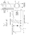
- FIG 1 shows a prior art antenna system 10 in which signals (of about 1 or 2 kV) from a coaxial (feeder) cable 12, are fed to a radiating mast 14 (mast radiator), where the electrical energy from the coaxial cable is radiated away.
- a radiating mast 14 mast radiator
- Such an antenna system will typically radiate at a power of 5 - 50kW.
- Typical transmission frequencies are in the LF-MF range (about 16 kHz to 2 MHz) and the mast is electrically "short” ; that is, the mast is a small fraction of the wavelength of the transmitted radio wave.
- the radio wave may be several kilometres in wavelength, whereas a mast will normally have a radiation length (that is, a height) of around 200m (or typically between 100m and 300m).
- an antenna matching network or other matching circuit 16 is provided between the coaxial cable 12 and the mast 14.
- the matching circuit 16 has a variable transformer 18 having a primary coil 20 and a secondary coil 22 the primary coil 20 being connected to the coaxial cable 12 (in parallel with a capacitor 24), whilst the secondary coil 22 is connected to a tuning inductor 26 having a variable inductance.
- the coils of the transformer and the inductor are normally formed from a Litz wire having a plurality of individually insulated strands (which may be woven together), so as to allow a more uniform current distribution through the wire.
- Both the primary and secondary coils 20, 22 of the transformer 18 are connected to a ground connection 28 (to which the sleeve of the coaxial cable is also connected), dark circles indicating a connection in figure 1.
- a ground connection 28 to which the sleeve of the coaxial cable is also connected
- dark circles indicating a connection in figure 1.
- electrical devices such as lighting devices 32 are secured to an upper portion of the mast with electrically insulating securing means 34.
- the lighting devices 32 normally operate at mains voltages (about 110-240V at less than 100 Hz, normally 50Hz) and are fed by electrical supply lines 36.
- the supply lines are insulated and are secured to the mast such that the supply lines extend in a generally vertical direction along the mast. Because the supply lines 36 are arranged in close proximity to the mast, there will be some capacitive coupling between the mast and the supply lines.
- the potential of the mast itself will typically be elevated to several tens of kV, for example 60 kV (oscillating at the signal frequency of 16 kHz to 2 MHz).
- the capacitive coupling between the mast and the supply lines therefore generates a significant common mode current in the supply lines.
- This common mode current is often isolated using an isolating transformer 40, having a core material 42 that is arranged to couple frequencies in the region of the mains frequencies (50Hz) but not the signal frequencies (at least several kHz).
- FIG. 2 shows an antenna system according to the present invention (components in figure 2 that are similar to those in figure 1 have the same numerals).
- a matching circuit 16 is provided between the coaxial cable 12 and the mast 14.
- the supply lines 36 follow the path of the secondary coil 22 and that of the tuning inductor 26.
- the supply lines are at substantially the same potential as the mast (except for the mains voltage applied across the supply lines) and the risk of a significant current at radio frequencies being coupled to the mains supply network is reduced.
- the coaxial cable has a sheath 12a connected to an earth rail and a core 12b connected to a live rail 42 of the matching circuit 16.
- the primary coil 20 is connected at a grounded end 44 to the ground rail 40, and at a live end 46 to the live rail 42.
- the primary coil is connected across the sheath and the core of the cable feeding the transmission signal (which transmission signals serves to power the mast such that it can radiate).
- a capacitor 24 is provided between the live rail 42 and the ground rail 44, in parallel with the primary coil 20.
- the secondary coil 22 includes a main set of windings 22a and a plurality of sets of subsidiary winding 22b (the electrical path formed by the main windings 22a and 26a in figure 2 have the same function as the windings of the secondary coil and inductor in figure 1).
- two sets of subsidiary windings 22b are provided, one for each of the supply lines 36.
- the tuning inductor 26 has a main set of windings 26a and a subsidiary set of windings 26b.
- the main set of windings of the secondary coil is connected at a ground end 48 to the ground rail 40.
- the main set of windings 22a of the secondary coil is connected to the main set of windings 26a of the tuning inductor, which in turn is connected to the radiating mast 14.
- the subsidiary sets of windings 22b of the secondary coil 22 are respectively connected to those of the tuning inductor 26.
- the subsidiary sets are connected to lighting devices 32 (or other electrical equipment mounted on the mast) via cables 37 extending along the mast.
- the subsidiary windings of the transformer 18 and those of the inductor 22 form part of a closed circuit (indicated by thin lines in figure 2) for carrying electrical power from an electrical supply, here a mains electrical supply 52, to the lighting devices on the mast.
- a spark gap device 53 is provided so that excessive voltage spikes can be discharged to ground by arcing across a spark gap extending between spaced apart electrodes.
- the main sets of windings of the secondary coil 22 and of the inductor 26 form an electrical path (indicated by a thick line in figure 2) between the ground rail 40 and the mast, over which electrical path an oscillating voltage is built up by induction, so as to cause suitable electric currents to be delivered to the mast for transmission as radio waves.
- the subsidiary windings in the secondary coil are arranged to follow the same path as those of the primary coil. This can be achieved by twisting or otherwise meshing a trio of electrically conducting wires around one another, one wire for each of the main and subsidiary coils, and subsequently winding the trio so as to form a tri-filar coil. Alternatively, the trio need not be twisted before being wound. The trio may be retained in a sheath before being wound, so as to form a cable which itself is wound such that the electrical path for feeding the mast and the electrical paths for a supplying the lighting devices are wound together at the secondary coil, and likewise at the tuneable inductor.
- a plurality of sets of supply lines may be wound together so as to form a multifillar coil, that is, a coil in which a plurality of electrical conductors follow adjacent coiled paths, or parallel-wound paths in which the windings from different conductors are interleaved (axially and/or radially).
- More than one set of supply lines may be used to power a plurality of devices mounted on the mast, which devices need different forms of power or signals.
- the devices may be radiating or receiving devices installed for third party providers (that is, an additional antenna).
- a set of supply lines may include more than two conductors, as will be the case when three phase power is supplied to the mast devices.
- the secondary coil will be formed by winding the trio around a cylindrical frame having an opening for receiving the primary coil, such that the primary coil can be at least partially inserted axially within the secondary coil.
- the coupling between the primary and secondary coils can be controlled in a known manner, for example by using a stepper motor to adjust the extent to which the primary coil is inserted within the secondary coil.
- the extent to which the first coil is within the secondary coil will determine the extent of the coupling, because the electrical wires run forming the main and subsidiary coils follow the same path, the coupling to each will be the same or very similar. In the event that the coupling to each wire is not the exactly the same, any imbalances can be absorbed by a capacitor arrangement 60 between the power supply 52 and the secondary coil 22 of the transformer 18.
- the tuning inductor 26 is formed in a similar fashion to the secondary coil, in that the main winding 26a and the subsidiary windings 26b are wound together as a common winding, thereby coupling the tuning inductor to the supply lines.
- a time-varying current through the primary coil of the transform 18 supplied by the coaxial cable 12 induces a time-varying Electro Motive Force (EMF) along the secondary coil 22.
- EMF Electro Motive Force
- a comparable or almost identical EMF is generated in each of the subsidiary winding, since the Electro Magnetic coupling between the primary coil and each of the main and subsidiary windings of the secondary coil will be almost the same.
- the EMF induced in the main winding and subsidiary windings of the tuning inductor 26 will be closely matched, since both follow the same path.
- the supply lines 36 will be a common mode voltage (i.e. the same for each supply line), and so the potential between the lines will remain at that set by the power supply 52 (240V). Furthermore, because the supply lines follow the path of the line feeding the mast, the mast and the supply lines will be at substantially the same potential as one another. Importantly, because the feed line supplying the mast is at ground potential at the ground end 48 of the secondary coil, the supply lines at the ground end of the secondary coil are unlikely to have any substantial radio frequency potential imposed thereon. Therefore, there is a reduced likelihood that current will be drawn from the power supply 52 at radio frequency rates.
- the matching circuit can be viewed as having a first path extending between the ground connection 48 and the mast (which is capacitively coupled to ground so as to from a closed ac circuit), along which path a voltage is developed at the secondary transformer coil and the tuning inductor.
- the matching circuit has also a second path extending though the primary transformer coil.
- the supply lines need only follow the path of the inductive elements in the first path, since it is across the inductive elements of the first path that the voltage applied to the mast is built up.
- the matching circuit may take different forms to that shown in the figures.
- the supply lines will preferably follow the path of or be otherwise embedded with inductive elements that build up a potential along a path extending between ground and the mast, rather than being embedded with all of the inductive elements that may be present in the circuit.
- a third party antennas could be installed. Such an antenna would be much smaller than the mast, and may be, for example, a Yagi (directional) antenna operating in the VHF or UHF frequency bands, either on receive, or transmitting typically 1 - 50 Watts.
- the feeds to these antennas could be multi-filar wound using twisted pairs as described above, or be connected to radio equipment mounted close to them on the mast, whereby power and base-band feeds to the radio equipment could be multi-filar as described above.
Landscapes
- Details Of Aerials (AREA)
Abstract
The present invention relates to an antenna system, in particular for an antenna system having an inductive element. There is provided an antenna system having: a mast for radiating radiation; an electrical circuit having at least one inductive element for coupling the mast to a feeder cable, which inductive element generates, in use, a radio frequency voltage; at least one electrical device mounted on the mast; and, supply lines for forming an electrical connection to the or each electrical device, wherein the supply lines are inductively coupled to the or at least one inductive element such that the radio frequency voltage is applied to the supply lines. Because the radio frequency voltage is applied to the supply lines, the supply lines are at the same potential as the mast, thereby reducing the need for an isolating to isolate the supply lines.
Description
- The present invention relates to an antenna system, in particular for an antenna system having an inductive element.
- Antenna systems operating in the radio frequency range (for example, 1 kHz to about 10 MHz are often electrically 'short'; that is, they have a radiating mast that is only a small fraction of the wavelength of the transmitted signal. As a result, an electrical circuit, known as a matching network, is used to couple the mast to the feed cable supplying electrical power to the aerial. This electrical circuit will normally have inductance, for example due to a transformer or other inductive element, which, in combination with the high currents passing through the electrical circuit, results in high radio frequency voltages being applied to the mast. This voltage can be of the order of 60kV.
- Commonly, a mast will have electrical devices such as aircraft warning lights mounted thereon, which devices are normally powered by the electrical mains. However, the supply lines needed to carry power to the electrical devices will normally extend along the mast, and as a result of the close proximity of the supply lines to the mast, undesirable radio frequency voltages or currents can arise in the supply lines. It is known to use an isolating transformer to isolate the radio frequency voltages or currents. However, such transformers can be costly.
- According to the present invention, there is provided an antenna system having: a mast for radiating radiation; an electrical circuit having at least one inductive element for coupling the mast to a feeder cable, which inductive element generates, in use, a radio frequency voltage; at least one electrical device mounted on the mast; and, supply lines for forming an electrical connection to the or each electrical device, wherein the supply lines are inductively coupled to at least one inductive element such that the radio frequency voltage is applied to the supply lines.
- Because the radio frequency voltage is applied to the supply lines, the supply lines will be at substantially the same potential as the mast, thereby reducing the need for an isolating transformer to isolate the supply lines.
- Preferably, the electrical circuit includes a transformer having a primary coil with a plurality of windings arranged in use to induce a voltage on a secondary coil, the supply lines being inductively coupled to the primary coil. The supply lines will preferably each have a coiled portion with a respective plurality of winding arranged such that substantially the same voltage is induced in the coiled portion as is induced in the secondary coil.
- In a preferred embodiment, this is achieved by arranging the windings of the secondary coil and those of the coiled portions so that they follow the same path. However, the windings of the coiled portions may follow different paths, provided that the magnetic flux coupled to the coiled portions is matched to that coupled to the secondary coil. Preferably, the coiled portions will each have substantially the same number of self-crossing loops or turns as the secondary coil.
- The electrical circuit will preferably have at least one additional inductive element, such as an inductor, along which, in use, a potential builds up, and which potential is applied to the mast. In a preferred embodiment, the coiled portions of the supply lines will each follow the path of the or each inductor winding, so that the same or similar potential is build up along the supply lines.
- At least one of the electrical devices mounted on the mast may be a light-emitting device, such as an aircraft warning light. However, in additional or alternatively, communication devices such as third party radio or microwave transmission systems may be installed on the mast. Such communication devices may require supply lines to supply mains power as well as supply lines to supply signals at frequencies above those of the mains frequencies.
- In a preferred embodiment, the mast is formed from an electrically conducting material such that it is able to radiate along its length, the mast being supported on a base, preferably an insulated base to insulate the mast from ground. Normally, the base will be short compared to the height of the mast. However, the base may be of substantial height, and may for example be formed by a building structure.
- The invention will now be described by way of example with reference to the following drawings in which:
- Figure 1 shows a prior art antenna system; and,
- Figure 2 shows an antenna system according to the present invention.
- Figure 1 shows a prior
art antenna system 10 in which signals (of about 1 or 2 kV) from a coaxial (feeder)cable 12, are fed to a radiating mast 14 (mast radiator), where the electrical energy from the coaxial cable is radiated away. Such an antenna system will typically radiate at a power of 5 - 50kW. Typical transmission frequencies are in the LF-MF range (about 16 kHz to 2 MHz) and the mast is electrically "short" ; that is, the mast is a small fraction of the wavelength of the transmitted radio wave. For example, the radio wave may be several kilometres in wavelength, whereas a mast will normally have a radiation length (that is, a height) of around 200m (or typically between 100m and 300m). In order to take into account this short mast length and match the impedance of the coaxial cable to the mast, an antenna matching network or other matchingcircuit 16 is provided between thecoaxial cable 12 and themast 14. Thematching circuit 16 has avariable transformer 18 having aprimary coil 20 and asecondary coil 22 theprimary coil 20 being connected to the coaxial cable 12 (in parallel with a capacitor 24), whilst thesecondary coil 22 is connected to atuning inductor 26 having a variable inductance. The coils of the transformer and the inductor are normally formed from a Litz wire having a plurality of individually insulated strands (which may be woven together), so as to allow a more uniform current distribution through the wire. - Both the primary and
secondary coils transformer 18 are connected to a ground connection 28 (to which the sleeve of the coaxial cable is also connected), dark circles indicating a connection in figure 1. Thus, current from thecoaxial cable 12 passes through the primary coil, and generates an EMF or voltage across the secondary coil. Because themast 14 is connected to the secondary coil (at an end thereof that is remote from the grounded end) the mast develops a potential in dependence on the signal from thecoaxial cable 12. Because of the capacitance of the mast, due in part to electrically conductingguy lines 30 extending from the mast and towards the ground, an oscillating current of flows along the mast in response to the oscillating signal from the coaxial cable, causing radiation to be emitted by the mast. - Often, electrical devices such as
lighting devices 32 are secured to an upper portion of the mast with electrically insulating securing means 34. Thelighting devices 32 normally operate at mains voltages (about 110-240V at less than 100 Hz, normally 50Hz) and are fed byelectrical supply lines 36. The supply lines are insulated and are secured to the mast such that the supply lines extend in a generally vertical direction along the mast. Because thesupply lines 36 are arranged in close proximity to the mast, there will be some capacitive coupling between the mast and the supply lines. Because of the high currents (several hundred Amps) passing through thetransformer 18 and thetuning inductor 26, the potential of the mast itself will typically be elevated to several tens of kV, for example 60 kV (oscillating at the signal frequency of 16 kHz to 2 MHz). The capacitive coupling between the mast and the supply lines therefore generates a significant common mode current in the supply lines. This common mode current is often isolated using anisolating transformer 40, having acore material 42 that is arranged to couple frequencies in the region of the mains frequencies (50Hz) but not the signal frequencies (at least several kHz). - Figure 2 shows an antenna system according to the present invention (components in figure 2 that are similar to those in figure 1 have the same numerals). As in the prior art, a
matching circuit 16 is provided between thecoaxial cable 12 and themast 14. However, here, thesupply lines 36 follow the path of thesecondary coil 22 and that of thetuning inductor 26. As a result of the inductive coupling to the supply lines, the supply lines are at substantially the same potential as the mast (except for the mains voltage applied across the supply lines) and the risk of a significant current at radio frequencies being coupled to the mains supply network is reduced. - In more detail, the coaxial cable has a sheath 12a connected to an earth rail and a core 12b connected to a
live rail 42 of the matchingcircuit 16. Theprimary coil 20 is connected at agrounded end 44 to theground rail 40, and at a live end 46 to thelive rail 42. Thus, the primary coil is connected across the sheath and the core of the cable feeding the transmission signal (which transmission signals serves to power the mast such that it can radiate). Acapacitor 24 is provided between thelive rail 42 and theground rail 44, in parallel with theprimary coil 20. Thesecondary coil 22 includes a main set of windings 22a and a plurality of sets of subsidiary winding 22b (the electrical path formed by the main windings 22a and 26a in figure 2 have the same function as the windings of the secondary coil and inductor in figure 1). In the present example, two sets of subsidiary windings 22b are provided, one for each of thesupply lines 36. - Likewise, the
tuning inductor 26 has a main set of windings 26a and a subsidiary set of windings 26b. - The main set of windings of the secondary coil is connected at a
ground end 48 to theground rail 40. At alive end 50, the main set of windings 22a of the secondary coil is connected to the main set of windings 26a of the tuning inductor, which in turn is connected to theradiating mast 14. - Likewise, the subsidiary sets of windings 22b of the
secondary coil 22 are respectively connected to those of thetuning inductor 26. In turn, the subsidiary sets are connected to lighting devices 32 (or other electrical equipment mounted on the mast) viacables 37 extending along the mast. In this way, the subsidiary windings of thetransformer 18 and those of theinductor 22 form part of a closed circuit (indicated by thin lines in figure 2) for carrying electrical power from an electrical supply, here a mainselectrical supply 52, to the lighting devices on the mast. - In view of the inductance of the matching circuit and for lightning protection, a
spark gap device 53 is provided so that excessive voltage spikes can be discharged to ground by arcing across a spark gap extending between spaced apart electrodes. - The main sets of windings of the
secondary coil 22 and of theinductor 26 form an electrical path (indicated by a thick line in figure 2) between theground rail 40 and the mast, over which electrical path an oscillating voltage is built up by induction, so as to cause suitable electric currents to be delivered to the mast for transmission as radio waves. - The subsidiary windings in the secondary coil are arranged to follow the same path as those of the primary coil. This can be achieved by twisting or otherwise meshing a trio of electrically conducting wires around one another, one wire for each of the main and subsidiary coils, and subsequently winding the trio so as to form a tri-filar coil. Alternatively, the trio need not be twisted before being wound. The trio may be retained in a sheath before being wound, so as to form a cable which itself is wound such that the electrical path for feeding the mast and the electrical paths for a supplying the lighting devices are wound together at the secondary coil, and likewise at the tuneable inductor.
- Clearly, a plurality of sets of supply lines may be wound together so as to form a multifillar coil, that is, a coil in which a plurality of electrical conductors follow adjacent coiled paths, or parallel-wound paths in which the windings from different conductors are interleaved (axially and/or radially). More than one set of supply lines may be used to power a plurality of devices mounted on the mast, which devices need different forms of power or signals. For example, the devices may be radiating or receiving devices installed for third party providers (that is, an additional antenna). Furthermore, a set of supply lines may include more than two conductors, as will be the case when three phase power is supplied to the mast devices.
- The secondary coil will be formed by winding the trio around a cylindrical frame having an opening for receiving the primary coil, such that the primary coil can be at least partially inserted axially within the secondary coil. The coupling between the primary and secondary coils can be controlled in a known manner, for example by using a stepper motor to adjust the extent to which the primary coil is inserted within the secondary coil. Although the extent to which the first coil is within the secondary coil will determine the extent of the coupling, because the electrical wires run forming the main and subsidiary coils follow the same path, the coupling to each will be the same or very similar. In the event that the coupling to each wire is not the exactly the same, any imbalances can be absorbed by a capacitor arrangement 60 between the
power supply 52 and thesecondary coil 22 of thetransformer 18. - The tuning
inductor 26 is formed in a similar fashion to the secondary coil, in that the main winding 26a and the subsidiary windings 26b are wound together as a common winding, thereby coupling the tuning inductor to the supply lines. - In operation, a time-varying current through the primary coil of the
transform 18 supplied by thecoaxial cable 12 induces a time-varying Electro Motive Force (EMF) along thesecondary coil 22. A comparable or almost identical EMF is generated in each of the subsidiary winding, since the Electro Magnetic coupling between the primary coil and each of the main and subsidiary windings of the secondary coil will be almost the same. Likewise, the EMF induced in the main winding and subsidiary windings of the tuninginductor 26 will be closely matched, since both follow the same path. - Thus, although there will be a radio frequency induced voltage on the
supply lines 36, it will be a common mode voltage (i.e. the same for each supply line), and so the potential between the lines will remain at that set by the power supply 52 (240V). Furthermore, because the supply lines follow the path of the line feeding the mast, the mast and the supply lines will be at substantially the same potential as one another. Importantly, because the feed line supplying the mast is at ground potential at theground end 48 of the secondary coil, the supply lines at the ground end of the secondary coil are unlikely to have any substantial radio frequency potential imposed thereon. Therefore, there is a reduced likelihood that current will be drawn from thepower supply 52 at radio frequency rates. - In practice, the paths followed by wires feeding the mast and the path followed by the wires forming the supply lines will not be exactly co-incident. As a result, there will be a small residual radio frequency voltage applied (e) between the supply lines themselves, and (b) between the supply lines and the mast. Therefore, a filtering circuit 56 may be necessary along the supply lines to remove the radio frequency signals before it reaches the lighting devices.
- The matching circuit can be viewed as having a first path extending between the
ground connection 48 and the mast (which is capacitively coupled to ground so as to from a closed ac circuit), along which path a voltage is developed at the secondary transformer coil and the tuning inductor. The matching circuit has also a second path extending though the primary transformer coil. Clearly, the supply lines need only follow the path of the inductive elements in the first path, since it is across the inductive elements of the first path that the voltage applied to the mast is built up. - It will be appreciated that the matching circuit may take different forms to that shown in the figures. In the case of the present matching circuit, as well as other possible circuits for feeding power to the mast, the supply lines will preferably follow the path of or be otherwise embedded with inductive elements that build up a potential along a path extending between ground and the mast, rather than being embedded with all of the inductive elements that may be present in the circuit.
- Instead or in addition to lighting devices, a third party antennas could be installed. Such an antenna would be much smaller than the mast, and may be, for example, a Yagi (directional) antenna operating in the VHF or UHF frequency bands, either on receive, or transmitting typically 1 - 50 Watts. The feeds to these antennas could be multi-filar wound using twisted pairs as described above, or be connected to radio equipment mounted close to them on the mast, whereby power and base-band feeds to the radio equipment could be multi-filar as described above.
Claims (11)
- An antenna system having: a mast for radiating radiation; an electrical circuit having at least one inductive element for coupling the mast to a feeder cable, which inductive element generates, in use, a radio frequency voltage; at least one electrical device mounted on the mast; and, supply lines for forming an electrical connection to the or each electrical device, wherein the supply lines are inductively coupled to the or at least one inductive element such that the radio frequency voltage is applied to the supply lines.
- An antenna system as claimed in claim 1, wherein the electrical circuit includes a transformer having a primary coil arranged in use to induce a voltage on a secondary coil, the supply lines being inductively coupled to the primary coil.
- An antenna system as claimed in claim 2, wherein the secondary coil has a plurality of windings, and the supply lines each have a respective coiled portion arranged along a path that follows the path of the windings.
- An antenna system as claimed in any of the preceding claims, wherein the electrical circuit has a plurality of circuit coils, and the supply lines each have a plurality of coiled portions, the coiled portions of each supply line following the path of a respective one of the circuit coils.
- An antenna system as claimed in any of the preceding claims, wherein at least one of the devices is a radiating device.
- An antenna system as claimed in claim 5, wherein the or each radiating device is a light-emitting device.
- An antenna system as claimed in any of the preceding claims, wherein the supply lines are arranged in use to supply power from a mains power supply.
- An antenna system as claimed in any of the preceding claims, wherein the supply lines are arranged in use to supply a oscillatory electrical current that oscillates at a frequency of less or equal to 100 Hz, preferably 50 Hz.
- An antenna system as claimed in any of the preceding claims, wherein at least one of the devices is a radiating device.
- An antenna system as claimed in any of the preceding claims, wherein the supply lines each have at least one coil inductively coupled to the or each respective inductive element of the electrical circuit.
- Antenna system as claimed in any of the preceding claims, wherein the electrical circuit is arranged to match the impedance of the mast to the impedance of the feeder cable.
Priority Applications (1)
| Application Number | Priority Date | Filing Date | Title |
|---|---|---|---|
| EP06255604A EP1919025A1 (en) | 2006-10-31 | 2006-10-31 | Antenna system with warning light |
Applications Claiming Priority (1)
| Application Number | Priority Date | Filing Date | Title |
|---|---|---|---|
| EP06255604A EP1919025A1 (en) | 2006-10-31 | 2006-10-31 | Antenna system with warning light |
Publications (1)
| Publication Number | Publication Date |
|---|---|
| EP1919025A1 true EP1919025A1 (en) | 2008-05-07 |
Family
ID=37891761
Family Applications (1)
| Application Number | Title | Priority Date | Filing Date |
|---|---|---|---|
| EP06255604A Withdrawn EP1919025A1 (en) | 2006-10-31 | 2006-10-31 | Antenna system with warning light |
Country Status (1)
| Country | Link |
|---|---|
| EP (1) | EP1919025A1 (en) |
Citations (4)
| Publication number | Priority date | Publication date | Assignee | Title |
|---|---|---|---|---|
| US2102410A (en) * | 1935-04-20 | 1937-12-14 | Goneral Electric Company | Antenna system |
| US2515061A (en) * | 1946-12-27 | 1950-07-11 | Bell Telephone Labor Inc | Radio-frequency filter |
| US4184165A (en) * | 1978-09-07 | 1980-01-15 | Stuart Electronics | Tuning system for tower antennas |
| DE19749750A1 (en) * | 1997-11-11 | 1999-06-02 | Hans E Dr Ing Speckter | Self-supporting tubular mast antenna for navigation system transmitter |
-
2006
- 2006-10-31 EP EP06255604A patent/EP1919025A1/en not_active Withdrawn
Patent Citations (4)
| Publication number | Priority date | Publication date | Assignee | Title |
|---|---|---|---|---|
| US2102410A (en) * | 1935-04-20 | 1937-12-14 | Goneral Electric Company | Antenna system |
| US2515061A (en) * | 1946-12-27 | 1950-07-11 | Bell Telephone Labor Inc | Radio-frequency filter |
| US4184165A (en) * | 1978-09-07 | 1980-01-15 | Stuart Electronics | Tuning system for tower antennas |
| DE19749750A1 (en) * | 1997-11-11 | 1999-06-02 | Hans E Dr Ing Speckter | Self-supporting tubular mast antenna for navigation system transmitter |
Similar Documents
| Publication | Publication Date | Title |
|---|---|---|
| KR101159565B1 (en) | Long range low frequency resonator and materials | |
| US7205947B2 (en) | Litzendraht loop antenna and associated methods | |
| KR101213006B1 (en) | Wireless energy transfer using coupled antennas | |
| RU2273939C1 (en) | Method and device for transferring electric energy (variants) | |
| US11133715B2 (en) | Wireless power transfer to multiple receiver devices across a variable-sized area | |
| US11515085B2 (en) | System for an inductive energy transmission from a primary-conductor system to a vehicle having a secondary winding | |
| AU2005299526B2 (en) | Arrangement of inductive couplers for data communication | |
| US10461410B2 (en) | Coaxial helix antennas | |
| KR20130130195A (en) | Transmitter used in wireless power transfer and wireless power transfer system having the same | |
| KR101163956B1 (en) | Resonant coil, apparatus for transmitting and receiveing a wireless power using the same | |
| AU2017301997B2 (en) | Coil assembly | |
| CA3058026C (en) | A system for wireless power transfer between low and high electrical potential, and a high voltage circuit breaker | |
| US9219315B2 (en) | Combination antenna | |
| EP0980156A2 (en) | Radio broadcasting system comprising an antenna system, which is constituted by at least a portion of the above-ground component of an electricity distribution network | |
| JPS62111529A (en) | Signal transmission equipment utilizing low voltage distribution line | |
| WO2003096481A1 (en) | Improvements to hf whip antenna | |
| NZ750454B2 (en) | Coil assembly | |
| PL216788B1 (en) | Electrically long medium wave frame type broadcasting antenna | |
| PL183554B1 (en) | Transmitting and receiving antenna |
Legal Events
| Date | Code | Title | Description |
|---|---|---|---|
| PUAI | Public reference made under article 153(3) epc to a published international application that has entered the european phase |
Free format text: ORIGINAL CODE: 0009012 |
|
| AK | Designated contracting states |
Kind code of ref document: A1 Designated state(s): AT BE BG CH CY CZ DE DK EE ES FI FR GB GR HU IE IS IT LI LT LU LV MC NL PL PT RO SE SI SK TR |
|
| AX | Request for extension of the european patent |
Extension state: AL BA HR MK RS |
|
| AKX | Designation fees paid | ||
| REG | Reference to a national code |
Ref country code: DE Ref legal event code: 8566 |
|
| STAA | Information on the status of an ep patent application or granted ep patent |
Free format text: STATUS: THE APPLICATION IS DEEMED TO BE WITHDRAWN |
|
| 18D | Application deemed to be withdrawn |
Effective date: 20081108 |