EP1918750A1 - Camera Module - Google Patents
Camera Module Download PDFInfo
- Publication number
- EP1918750A1 EP1918750A1 EP07119627A EP07119627A EP1918750A1 EP 1918750 A1 EP1918750 A1 EP 1918750A1 EP 07119627 A EP07119627 A EP 07119627A EP 07119627 A EP07119627 A EP 07119627A EP 1918750 A1 EP1918750 A1 EP 1918750A1
- Authority
- EP
- European Patent Office
- Prior art keywords
- dust
- base
- holder
- camera module
- lens unit
- Prior art date
- Legal status (The legal status is an assumption and is not a legal conclusion. Google has not performed a legal analysis and makes no representation as to the accuracy of the status listed.)
- Granted
Links
- 239000000428 dust Substances 0.000 claims abstract description 101
- 230000003287 optical effect Effects 0.000 claims description 18
- 238000003384 imaging method Methods 0.000 claims description 13
- 229920005989 resin Polymers 0.000 claims description 8
- 239000011347 resin Substances 0.000 claims description 8
- 239000004593 Epoxy Substances 0.000 claims description 4
- -1 acryl Chemical group 0.000 claims description 4
- 230000035939 shock Effects 0.000 abstract description 2
- 239000011521 glass Substances 0.000 description 11
- 229920003002 synthetic resin Polymers 0.000 description 8
- 239000000057 synthetic resin Substances 0.000 description 8
- 239000000945 filler Substances 0.000 description 6
- 239000000853 adhesive Substances 0.000 description 3
- 230000001070 adhesive effect Effects 0.000 description 3
- 230000001413 cellular effect Effects 0.000 description 2
- 230000003993 interaction Effects 0.000 description 2
- DMFGNRRURHSENX-UHFFFAOYSA-N beryllium copper Chemical compound [Be].[Cu] DMFGNRRURHSENX-UHFFFAOYSA-N 0.000 description 1
- 230000008859 change Effects 0.000 description 1
- 238000006073 displacement reaction Methods 0.000 description 1
- 230000004907 flux Effects 0.000 description 1
- 229910052751 metal Inorganic materials 0.000 description 1
- 239000002184 metal Substances 0.000 description 1
- 239000007769 metal material Substances 0.000 description 1
- 238000000034 method Methods 0.000 description 1
- 230000008569 process Effects 0.000 description 1
- 238000004080 punching Methods 0.000 description 1
Images


Classifications
-
- G—PHYSICS
- G02—OPTICS
- G02B—OPTICAL ELEMENTS, SYSTEMS OR APPARATUS
- G02B27/00—Optical systems or apparatus not provided for by any of the groups G02B1/00 - G02B26/00, G02B30/00
- G02B27/0006—Optical systems or apparatus not provided for by any of the groups G02B1/00 - G02B26/00, G02B30/00 with means to keep optical surfaces clean, e.g. by preventing or removing dirt, stains, contamination, condensation
-
- G—PHYSICS
- G02—OPTICS
- G02B—OPTICAL ELEMENTS, SYSTEMS OR APPARATUS
- G02B13/00—Optical objectives specially designed for the purposes specified below
- G02B13/001—Miniaturised objectives for electronic devices, e.g. portable telephones, webcams, PDAs, small digital cameras
-
- H—ELECTRICITY
- H02—GENERATION; CONVERSION OR DISTRIBUTION OF ELECTRIC POWER
- H02K—DYNAMO-ELECTRIC MACHINES
- H02K41/00—Propulsion systems in which a rigid body is moved along a path due to dynamo-electric interaction between the body and a magnetic field travelling along the path
- H02K41/02—Linear motors; Sectional motors
- H02K41/035—DC motors; Unipolar motors
- H02K41/0352—Unipolar motors
- H02K41/0354—Lorentz force motors, e.g. voice coil motors
- H02K41/0356—Lorentz force motors, e.g. voice coil motors moving along a straight path
Definitions
- This invention relates to a camera module, and more specifically to a camera module that can be used in small-sized electronic apparatuses such as digital cameras, camera-equipped cellular phones and the like.
- a camera module having a function of displacing a lens unit in a direction of an optical axis of the lens unit is used in relatively small-sized digital cameras, camera-equipped cellular phones and the like.
- This function is used for providing an autofocus function and/or zoom function and the like, and is achieved by an interaction between a magnetic field generated by an electrical current flowing in a coil and a magnetic field generated by a yoke and magnets provided on the yoke.
- Such a camera module generally includes a barrel which holds the lens unit, a holder which houses the barrel therein, and a pair of leaf springs for supporting the holder so that the holder is displaceable in a direction of an optical axis of the lens unit.
- FIG. 3 is an exploded perspective view of an autofocus actuator assembly 100 used in a conventional camera module for displacing a lens unit (not shown) in a direction of an optical axis thereof. It is to be noted that an imaging element (not shown) is provided below a base 111 of the actuator assembly 100.
- a holder 108 that houses a barrel (not shown) holding the lens unit is provided in a space between a cover 101 and the base ill so that the holder 108 is displaceable in a direction of an optical axis of the lens unit together with the lens unit.
- An inner annular portion 104b of an upper leaf spring 104 and an inner annular portion 110b of a lower leaf spring 110 are attached to upper and lower cylindrical end portions of the holder 108, respectively, using an adhesive. Further, an outer annular portion 104a of the upper leaf spring 104 is attached to a top surface of a yoke 105 and an outer annular portion 110a of the lower leaf spring 110 is provided on a lower end of the yoke 105, respectively. Furthermore, on the upper surface of the inner annular portion 104b of the upper spring 104 which is attached to the upper cylindrical end portion of the holder 108, a stopper denoted by the reference numeral 102 is attached using an adhesive.
- Three bridge portions 104c are coupled between the outer annular portion 104a and the inner annular portion 104b of the upper leaf spring 104.
- three bridge portions 110c are coupled between the outer annular portion 110a and the inner annular portion 110b of the upper leaf spring 110.
- a plurality of magnets 1.06 are provided on the yoke 105 so as to produce a magnetic field.
- the yoke 105 has an axial bore 105a for receiving the holder 108.
- a coil 107 is provided around an outer periphery of a cylindrical portion of the holder 108 so that the coil 7 is disposed in the magnetic field produced by the magnets 106 and the yoke 105 in a state that the holder 108 is received in the axial bore 105a.
- a component donated by the reference numeral 109 in FIG. 3 is a ring-shaped plate provided between the lower leaf spring 110 and the lower end of the yoke 105. Further, a flexible printed circuit board 103 for supplying an electrical current to the coil 107 is provided below the outer annular portion 110a of the lower leaf spring 110.
- the base 111 has a base upper surface 111c having an opening 111a at a center thereof defined by an edge I11b, and the base upper surface 111c is formed into a flat surface continued to the edge 111b.
- the components such as the cover 101, the stopper 102, the holder 108 and the base 111 are molded parts made of synthetic resins containing glass filler as aggregate.
- the actuator assembly 100 includes the components such as the cover 101, the stopper 102, the holder 108 and the base 111 which are made of synthetic resins containing glass filler as aggregate. Therefore, when the small-sized electronic apparatuses equipped with the camera module is dropped by an accident, there is a case that dust which is formed from glass filler or synthetic resins chipped from the molded parts is generated. If such dust is generated, there is a case that such dust is fallen onto the base upper surface 111c of the base 111, then fallen into the opening 111a over the edge 111b, and finally fallen onto a surface of an upper lid glass (not shown) disposed in an imaging area including the imaging element. If such dust is fallen onto the surface of the lid glass and adheres thereto, there arises a problem in that burred dots appear on an image obtained by the camera module.
- the present invention has been made in view of the problem described above, and therefore it is an object of the present invention to provide a camera module that can obtain a clear image even in the case where dust is generated inside the camera module due to a shock applied thereto.
- the present invention is directed to a camera module, which comprises: a lens unit which constitutes an optical system of the camera module; a holder which has a hollow cylindrical portion that houses the lens unit therein and is displaceable along an optical axis direction of the lens unit; a coil having a cylindrical form and provided around the cylindrical portion of the holder; a yoke and magnets provided on the yoke for providing a magnetic field to the coil; upper and lower leaf springs for supporting the holder so that the holder is displaceable along an optical axis direction of the lens unit; a base which supports the yoke, and has an opening at a center thereof; a cover attached to the base so as to define a space therebetween in which the holder 8 can be displaced; and an imaging element provided below the base.
- the base has an upper surface which faces the cover, and the upper surface of the base includes a concaved dust collecting portion and a dust falling preventing wall formed on the upper surface so as to surround an entire circumference of the opening of the base, and wherein a surface of the concaved dust collecting portion includes a dust sticking layer to which fallen dust is adapted to stick, whereby when dust is generated in the space between the cover and the base and such dust is fallen onto the upper surface of the base, it is possible to prevent such dust from entering (falling) into the opening by the dust falling preventing wall and such dust is stuck to the dust sticking layer of the dust collecting portion provided on the upper surface of the base.
- the camera module of the present invention having the above structure, when the small-sized electronic apparatuses equipped with the camera module is dropped by an accident, and thereby dust is generated inside the space between the cover and the base, there is less possibility that such dust falls on the surface of an upper lid glass disposed in an imaging area of the imaging element. This is because when such dust generated inside the space is fallen onto the upper surface of the base, it is possible to prevent such dust from being fallen into the opening due to the dust falling preventing wall, and further such dust is stuck to the dust sticking layer provided on the surface of the concaved dust collecting portion. Therefore, even in the event that the small-sized electronic apparatuses equipped with the camera module is dropped by an accident and thus dust is generated inside the camera module, it is possible to obtain a clear image.
- the dust sticking layer of the dust collecting portion provided in the upper surface of the base includes a thin layer made of an epoxy-based resin or an acryl-based resin.
- the camera module of the present invention having the above structure, it is possible to collect such dust fallen onto the upper surface of the base by the dust collecting portion reliably, thereby enabling to prevent such dust from being fallen into the opening of the base.
- a camera module according to an embodiment of the present invention will be described below with reference to the accompanying drawing.
- the camera module comprises: a lens unit (not shown) which constitutes an optical system of the camera module; a holder 8 which has a hollow cylindrical portion that houses the lens unit therein and is displaceable along an optical axis direction of the lens unit; a coil 7 having a cylindrical form and provided around the cylindrical portion of the holder 8; a yoke 5 and magnets 6 provided on the yoke 5 for providing a magnetic field to the coil; upper and lower leaf springs 4, 10 for supporting the holder 8 so that the holder 8 is displaceable along an optical axis direction of the lens unit; a base 12 which supports the yoke and has an opening 12a at a center thereof; a cover 2 attached to the base 12 so as to define a space therebetween in which the holder 8 can be displaced; and an imaging element (not shown) provided below the base 12, wherein the camera module is characterized in that the base 12 has an upper surface which faces the cover 2, and the upper surface of the base 12 includes a concaved dust collecting portion
- the holder 8 which houses a barrel (not shown) holding the lens unit is provided so as to be displaceable in an optical axis direction of the lens unit.
- the holder 8 is a cylindrical member made of a synthetic resin which contains glass filler as aggregate and the coil 7 is provided around the cylindrical portion of the holder 8.
- An inner annular portion 4b of the upper leaf spring 4 is attached an upper cylindrical end portion of the holder 8 and an inner annular portion 10b of the lower leaf spring 10 is attached to a lower cylindrical end portion of the holder 8, respectively.
- an outer annular portion 4a of the upper leaf spring 4 is attached to a top surface of the yoke 5 provided on the base 12 and an outer annular portion 10a of the lower leaf spring 10 is attached to a lower end portion of the yoke 5 through an annular plate 19.
- a stopper 3 is attached using an adhesive.
- This stopper 3 is also formed of a synthetic resin containing glass filler as aggregate, and it is provided for restricting upwardly excessive displacement of the holder 8 by the abutment with the bottom surface of the cover 2 when the holder 8 is largely displaced.
- Each of the upper and lower leaf springs 4, 10 is formed from a thin metal plate made of beryllium copper through a punching process so as to have the outer annular portion 4a, 10a and the inner annular portion 4b, 10b which is concentrically provided inside the outer annular portion 4a, 10a through an annular spacing.
- the inner annular portion 4b, 10b is displaceably supported by the outer annular portion 4a, 10a through the three bridge portions 4c, 10c.
- Each of the bridge portions 4c, 10c has an elongated arc-shape which extends along the inner periphery of the outer annular portion 4a, 10a and the outer periphery of the inner annular portion 4b, 10b in the space through a predetermined angle.
- the plurality of magnets 6 are bonded to the inner surface of the yoke 5 so as to produce a magnetic field.
- the coil 7 is provided around an outer periphery of the cylindrical portion of the holder 8 so that the coil 7 is disposed in the magnetic field generated by the magnets 6 and the yoke 5.
- the yoke 5 has an axial bore 5a for receiving the holder 8.
- the holder 8 can be displaced through the axial bore 5a in a direction of an optical axis of the lens unit by supplying an electrical current to the coil 7.
- the annular plate 9 made of a magnetic metal material is provided between the lower leaf spring 10 and the bottom surface of the yoke 5 for reducing leakage of magnetic fluxes from the magnets 6.
- a component denoted by the reference numeral 11 is a flexible printed circuit board used for supplying a current to the coil 7.
- the base 12 is also a molded part made of a synthetic resin containing glass filler as aggregate. As shown in FIGS. 1 and 2 , the base has the opening 12a at a center thereof. This opening 12a is provided for introducing light from the lens unit held inside the holder 8 to the imaging element provided below the base 12 . Beneath the opening 12a, an upper lid glass (not shown) which is disposed in an imaging area including the imaging element is arranged.
- the concaved dust collecting portion 12c is formed in the upper surface of the base 12 which faces the cover 2, the concaved dust collecting portion 12c is formed. Further, the surface of the concaved dust collecting portion 12c includes the dust sticking layer 12d.
- This dust sticking layer 12d is a thin layer made of a synthetic resin, which is formed by applying a synthetic resin having a fixation property and a softening property such as an epoxy-based resin or an acryl-based resin or the like.
- the dust collecting portion 12c can collect dust fallen onto the upper surface of the base 12 since such dust is stuck to the dust sticking layer 12d.
- the dust sticking layer 12d is provided over the entire of the upper surface of the base 12.
- the dust falling preventing wall 12b is formed so as to surround an entire circumference of the opening 12a of the base 12.
- the dust falling preventing wall 12b is a wall protruding toward the cover 2, which acts as a part of the concaved dust collecting portion 12c.
- the dust falling preventing wall 12b is a part of a vertical wall which constitutes a concaved portion of the concaved dust collecting portion 12c, and it prevents dust fallen onto the dust collecting portion 12c form being fallen into the opening 12a of the base 12.
- the camera module of this embodiment described above when the small-sized electronic apparatuses equipped with the camera module is dropped by an accident, and thereby dust is generated inside the space between the cover 2 and the base 12, there is less possibility that such dust falls on the surface of the upper lid glass disposed in the imaging area of the imaging element. This is because when such dust generated inside the space is fallen onto the upper surface of the base 12, it is possible to prevent such dust from being fallen into the opening 12a due to the dust falling preventing wall 12b, and further such dust is stuck to the dust sticking layer 12d provided on the surface of the concaved dust collecting portion 12c. Therefore, even in the event that the small-sized electronic apparatuses equipped with the camera module is dropped by an accident and thus dust is generated inside the camera module, it is possible to obtain a clear image.
- the dust sticking layer 12d is formed from a thin layer made of an epoxy-based resin or an acryl-based resin or the like, it is possible to collect such dust fallen onto the upper surface of the base 12 by the dust collecting portion 12c reliably, thereby enabling to prevent such dust from being fallen into the opening 12a of the base 12.
- the shapes and located areas of the dust collecting portion 12c and the dust falling preventing wall 12b of this embodiment is mere one example, and it is also possible to change them into other shapes according to shapes of the base and the like.
Landscapes
- Physics & Mathematics (AREA)
- General Physics & Mathematics (AREA)
- Optics & Photonics (AREA)
- Engineering & Computer Science (AREA)
- Chemical & Material Sciences (AREA)
- Combustion & Propulsion (AREA)
- Electromagnetism (AREA)
- Power Engineering (AREA)
- Studio Devices (AREA)
- Lens Barrels (AREA)
- Camera Bodies And Camera Details Or Accessories (AREA)
Abstract
Description
- This invention relates to a camera module, and more specifically to a camera module that can be used in small-sized electronic apparatuses such as digital cameras, camera-equipped cellular phones and the like.
- A camera module having a function of displacing a lens unit in a direction of an optical axis of the lens unit is used in relatively small-sized digital cameras, camera-equipped cellular phones and the like. This function is used for providing an autofocus function and/or zoom function and the like, and is achieved by an interaction between a magnetic field generated by an electrical current flowing in a coil and a magnetic field generated by a yoke and magnets provided on the yoke.
- Such a camera module generally includes a barrel which holds the lens unit, a holder which houses the barrel therein, and a pair of leaf springs for supporting the holder so that the holder is displaceable in a direction of an optical axis of the lens unit.
- FIG. 3 is an exploded perspective view of an
autofocus actuator assembly 100 used in a conventional camera module for displacing a lens unit (not shown) in a direction of an optical axis thereof. It is to be noted that an imaging element (not shown) is provided below abase 111 of theactuator assembly 100. - A
holder 108 that houses a barrel (not shown) holding the lens unit is provided in a space between acover 101 and the base ill so that theholder 108 is displaceable in a direction of an optical axis of the lens unit together with the lens unit. - An inner
annular portion 104b of anupper leaf spring 104 and an innerannular portion 110b of alower leaf spring 110 are attached to upper and lower cylindrical end portions of theholder 108, respectively, using an adhesive. Further, an outerannular portion 104a of theupper leaf spring 104 is attached to a top surface of ayoke 105 and an outerannular portion 110a of thelower leaf spring 110 is provided on a lower end of theyoke 105, respectively. Furthermore, on the upper surface of the innerannular portion 104b of theupper spring 104 which is attached to the upper cylindrical end portion of theholder 108, a stopper denoted by thereference numeral 102 is attached using an adhesive. - Three
bridge portions 104c are coupled between the outerannular portion 104a and the innerannular portion 104b of theupper leaf spring 104. As is the same with theupper leaf spring 104, threebridge portions 110c are coupled between the outerannular portion 110a and the innerannular portion 110b of theupper leaf spring 110. By resilient deformation of the respective threebridge portions holder 108 can be displaced in a direction of an optical axis of the lens unit. - A plurality of magnets 1.06 are provided on the
yoke 105 so as to produce a magnetic field. Theyoke 105 has anaxial bore 105a for receiving theholder 108. Further, acoil 107 is provided around an outer periphery of a cylindrical portion of theholder 108 so that thecoil 7 is disposed in the magnetic field produced by themagnets 106 and theyoke 105 in a state that theholder 108 is received in theaxial bore 105a. By supplying a current to thecoil 107 to generate a magnetic field, theholder 108 can be displaced in a direction of an optical axis of the lens unit by a driving force generated by the interaction of the magnetic fields. In this regard, it is to be noted that a component donated by thereference numeral 109 in FIG. 3 is a ring-shaped plate provided between thelower leaf spring 110 and the lower end of theyoke 105. Further, a flexible printedcircuit board 103 for supplying an electrical current to thecoil 107 is provided below the outerannular portion 110a of thelower leaf spring 110. - As shown in FIG. 4, the
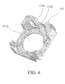
base 111 has a baseupper surface 111c having anopening 111a at a center thereof defined by an edge I11b, and the baseupper surface 111c is formed into a flat surface continued to the edge 111b. - In the
actuator assembly 100 described above, the components such as thecover 101, thestopper 102, theholder 108 and thebase 111 are molded parts made of synthetic resins containing glass filler as aggregate. - It is to be noted that an actuator assembly similar to the
actuator assembly 100 described above is disclosed inJP-A-No.2004-280031 - As described above, the
actuator assembly 100 includes the components such as thecover 101, thestopper 102, theholder 108 and thebase 111 which are made of synthetic resins containing glass filler as aggregate. Therefore, when the small-sized electronic apparatuses equipped with the camera module is dropped by an accident, there is a case that dust which is formed from glass filler or synthetic resins chipped from the molded parts is generated. If such dust is generated, there is a case that such dust is fallen onto the baseupper surface 111c of thebase 111, then fallen into the opening 111a over the edge 111b, and finally fallen onto a surface of an upper lid glass (not shown) disposed in an imaging area including the imaging element. If such dust is fallen onto the surface of the lid glass and adheres thereto, there arises a problem in that burred dots appear on an image obtained by the camera module. - The present invention has been made in view of the problem described above, and therefore it is an object of the present invention to provide a camera module that can obtain a clear image even in the case where dust is generated inside the camera module due to a shock applied thereto.
- In order to achieve the object, the present invention is directed to a camera module, which comprises: a lens unit which constitutes an optical system of the camera module; a holder which has a hollow cylindrical portion that houses the lens unit therein and is displaceable along an optical axis direction of the lens unit; a coil having a cylindrical form and provided around the cylindrical portion of the holder; a yoke and magnets provided on the yoke for providing a magnetic field to the coil; upper and lower leaf springs for supporting the holder so that the holder is displaceable along an optical axis direction of the lens unit; a base which supports the yoke, and has an opening at a center thereof; a cover attached to the base so as to define a space therebetween in which the
holder 8 can be displaced; and an imaging element provided below the base. The base has an upper surface which faces the cover, and the upper surface of the base includes a concaved dust collecting portion and a dust falling preventing wall formed on the upper surface so as to surround an entire circumference of the opening of the base, and wherein a surface of the concaved dust collecting portion includes a dust sticking layer to which fallen dust is adapted to stick, whereby when dust is generated in the space between the cover and the base and such dust is fallen onto the upper surface of the base, it is possible to prevent such dust from entering (falling) into the opening by the dust falling preventing wall and such dust is stuck to the dust sticking layer of the dust collecting portion provided on the upper surface of the base. - According to the camera module of the present invention having the above structure, when the small-sized electronic apparatuses equipped with the camera module is dropped by an accident, and thereby dust is generated inside the space between the cover and the base, there is less possibility that such dust falls on the surface of an upper lid glass disposed in an imaging area of the imaging element. This is because when such dust generated inside the space is fallen onto the upper surface of the base, it is possible to prevent such dust from being fallen into the opening due to the dust falling preventing wall, and further such dust is stuck to the dust sticking layer provided on the surface of the concaved dust collecting portion. Therefore, even in the event that the small-sized electronic apparatuses equipped with the camera module is dropped by an accident and thus dust is generated inside the camera module, it is possible to obtain a clear image.
- In the camera module of the present invention, it is preferred that the dust sticking layer of the dust collecting portion provided in the upper surface of the base includes a thin layer made of an epoxy-based resin or an acryl-based resin.
- According to the camera module of the present invention having the above structure, it is possible to collect such dust fallen onto the upper surface of the base by the dust collecting portion reliably, thereby enabling to prevent such dust from being fallen into the opening of the base.
- The above and other objects, features and advantages of the present invention will be apparent from the following description when taken in conjunction with the accompanying drawings which illustrate a preferred embodiment of the present invention by way of example.
-
- FIG. 1 is an exploded perspective view of an actuator assembly '1 of a camera module of an embodiment according to the present invention.
- FIG. 2 is an enlarged perspective view of a
base 12 of the camera module shown in FIG. 1. - FIG. 3 is an exploded perspective view of an
actuator assembly 100 of a conventional camera module. - FIG. 4 is an enlarged perspective view of a
base 111 of the camera module shown in FIG. 3. - A camera module according to an embodiment of the present invention will be described below with reference to the accompanying drawing.
- The camera module according to this embodiment comprises: a lens unit (not shown) which constitutes an optical system of the camera module; a
holder 8 which has a hollow cylindrical portion that houses the lens unit therein and is displaceable along an optical axis direction of the lens unit; acoil 7 having a cylindrical form and provided around the cylindrical portion of theholder 8; a yoke 5 andmagnets 6 provided on the yoke 5 for providing a magnetic field to the coil; upper andlower leaf springs holder 8 so that theholder 8 is displaceable along an optical axis direction of the lens unit; abase 12 which supports the yoke and has an opening 12a at a center thereof; a cover 2 attached to thebase 12 so as to define a space therebetween in which theholder 8 can be displaced; and an imaging element (not shown) provided below thebase 12, wherein the camera module is characterized in that thebase 12 has an upper surface which faces the cover 2, and the upper surface of thebase 12 includes a concaveddust collecting portion 12c and a dust falling preventingwall 12b formed on the upper surface so as to surround an entire circumference of the opening 12a of thebase 12, and wherein a surface of the concaveddust collecting portion 12c includes adust sticking layer 12d to which fallen dust is adapted to stick, whereby when dust is generated in the space between the cover 2 and thebase 12 and such dust falls onto the upper surface of thebase 12, it is possible to prevent such dust from entering into the opening 12c by the dust falling preventingwall 12b and such dust is adapted to stick to thedust sticking layer 12d of thedust collecting portion 12c provided on the upper surface of thebase 12. - Hereinbelow, with reference to FIG. 1, a description is made with regard to an actuator assembly 1 of the camera module of the embodiment according to the present invention in more details.
- In a space defined between the cover 2 and the
base 12, theholder 8 which houses a barrel (not shown) holding the lens unit is provided so as to be displaceable in an optical axis direction of the lens unit. - The
holder 8 is a cylindrical member made of a synthetic resin which contains glass filler as aggregate and thecoil 7 is provided around the cylindrical portion of theholder 8. An innerannular portion 4b of theupper leaf spring 4 is attached an upper cylindrical end portion of theholder 8 and an innerannular portion 10b of thelower leaf spring 10 is attached to a lower cylindrical end portion of theholder 8, respectively. Further, an outerannular portion 4a of theupper leaf spring 4 is attached to a top surface of the yoke 5 provided on thebase 12 and an outerannular portion 10a of thelower leaf spring 10 is attached to a lower end portion of the yoke 5 through an annular plate 19. Furthermore, on the upper surface of the innerannular portion 4b of theupper spring 4 which is attached to the upper cylindrical end portion of theholder 8, a stopper 3 is attached using an adhesive. This stopper 3 is also formed of a synthetic resin containing glass filler as aggregate, and it is provided for restricting upwardly excessive displacement of theholder 8 by the abutment with the bottom surface of the cover 2 when theholder 8 is largely displaced. - Each of the upper and
lower leaf springs annular portion annular portion annular portion lower leaf springs annular portion annular portion bridge portions 4c, 10c. Each of thebridge portions 4c, 10c has an elongated arc-shape which extends along the inner periphery of the outerannular portion annular portion bridge portions 4c and 10c, theholder 8 can be displaced in a direction of an optical axis of the lens unit. - The plurality of
magnets 6 are bonded to the inner surface of the yoke 5 so as to produce a magnetic field. Further, thecoil 7 is provided around an outer periphery of the cylindrical portion of theholder 8 so that thecoil 7 is disposed in the magnetic field generated by themagnets 6 and the yoke 5. The yoke 5 has anaxial bore 5a for receiving theholder 8. Theholder 8 can be displaced through theaxial bore 5a in a direction of an optical axis of the lens unit by supplying an electrical current to thecoil 7. Further, theannular plate 9 made of a magnetic metal material is provided between thelower leaf spring 10 and the bottom surface of the yoke 5 for reducing leakage of magnetic fluxes from themagnets 6. In this regard, it is to be noted that a component denoted by thereference numeral 11 is a flexible printed circuit board used for supplying a current to thecoil 7. - The
base 12 is also a molded part made of a synthetic resin containing glass filler as aggregate. As shown in FIGS. 1 and 2 , the base has the opening 12a at a center thereof. Thisopening 12a is provided for introducing light from the lens unit held inside theholder 8 to the imaging element provided below thebase 12 . Beneath theopening 12a, an upper lid glass (not shown) which is disposed in an imaging area including the imaging element is arranged. - As, described above, in the upper surface of the base 12 which faces the cover 2, the concaved
dust collecting portion 12c is formed. Further, the surface of the concaveddust collecting portion 12c includes thedust sticking layer 12d. Thisdust sticking layer 12d is a thin layer made of a synthetic resin, which is formed by applying a synthetic resin having a fixation property and a softening property such as an epoxy-based resin or an acryl-based resin or the like. Thedust collecting portion 12c can collect dust fallen onto the upper surface of the base 12 since such dust is stuck to thedust sticking layer 12d. In this regard, it is to be noted that in this embodiment thedust sticking layer 12d is provided over the entire of the upper surface of thebase 12. - Further, on the upper surface of the
base 12, the dust falling preventingwall 12b is formed so as to surround an entire circumference of theopening 12a of thebase 12. As shown in FIGS. 1 and 2, the dust falling preventingwall 12b is a wall protruding toward the cover 2, which acts as a part of the concaveddust collecting portion 12c. Namely, the dust falling preventingwall 12b is a part of a vertical wall which constitutes a concaved portion of the concaveddust collecting portion 12c, and it prevents dust fallen onto thedust collecting portion 12c form being fallen into theopening 12a of thebase 12. - According to the camera module of this embodiment described above, when the small-sized electronic apparatuses equipped with the camera module is dropped by an accident, and thereby dust is generated inside the space between the cover 2 and the
base 12, there is less possibility that such dust falls on the surface of the upper lid glass disposed in the imaging area of the imaging element. This is because when such dust generated inside the space is fallen onto the upper surface of thebase 12, it is possible to prevent such dust from being fallen into theopening 12a due to the dust falling preventingwall 12b, and further such dust is stuck to thedust sticking layer 12d provided on the surface of the concaveddust collecting portion 12c. Therefore, even in the event that the small-sized electronic apparatuses equipped with the camera module is dropped by an accident and thus dust is generated inside the camera module, it is possible to obtain a clear image. - Further, in the camera module of this embodiment, since the
dust sticking layer 12d is formed from a thin layer made of an epoxy-based resin or an acryl-based resin or the like, it is possible to collect such dust fallen onto the upper surface of the base 12 by thedust collecting portion 12c reliably, thereby enabling to prevent such dust from being fallen into theopening 12a of thebase 12. - In the above description, it is to be noted that the shapes and located areas of the
dust collecting portion 12c and the dust falling preventingwall 12b of this embodiment is mere one example, and it is also possible to change them into other shapes according to shapes of the base and the like. - Finally, it is also to be understood that the present disclosure relates to subject matter contained in
Japanese Patent Application No. 2006-2943032 (filed on October 30, 2006
Claims (2)
- A camera module, comprising:a lens unit which constitutes an optical system of the camera module;a holder which has a hollow cylindrical portion that houses the lens unit therein and is displaceable along an optical axis direction of the lens unit;a coil having a cylindrical form and provided around the cylindrical portion of the holder;a yoke and magnets provided on the yoke for providing a magnetic field to the coil;upper and lower leaf springs for supporting the holder so that the holder is displaceable along an optical axis direction of the lens unit;a base which supports the yoke, and has an opening at a center thereof;a cover attached to the base so as to define a space therebetween in which the holder 8 can be displaced; andan imaging element provided below the base,wherein the base has an upper surface which faces the cover, and the upper surface of the base includes a concaved dust collecting portion and a dust falling preventing wall formed on the upper surface so as to surround an entire circumference of the opening of the base, and wherein a surface of the concaved dust collecting portion includes a dust sticking layer to which fallen dust is adapted to stick, whereby when dust is generated in the space between the cover and the base and such dust is fallen onto the upper surface of the base, it is possible to prevent such dust from entering into the opening due to the dust falling preventing wall and such dust is stuck to the dust sticking layer of the dust collecting portion provided on the upper surface of the base.
- The camera module as claimed in claim 1, wherein the dust sticking layer of the dust collecting portion provided in the upper surface of the base includes a thin layer made of an epoxy-based resin or an acryl-based resin.
Applications Claiming Priority (1)
| Application Number | Priority Date | Filing Date | Title |
|---|---|---|---|
| JP2006294303A JP4315182B2 (en) | 2006-10-30 | 2006-10-30 | The camera module |
Publications (2)
| Publication Number | Publication Date |
|---|---|
| EP1918750A1 true EP1918750A1 (en) | 2008-05-07 |
| EP1918750B1 EP1918750B1 (en) | 2009-09-02 |
Family
ID=39023468
Family Applications (1)
| Application Number | Title | Priority Date | Filing Date |
|---|---|---|---|
| EP07119627A Not-in-force EP1918750B1 (en) | 2006-10-30 | 2007-10-30 | Camera Module |
Country Status (4)
| Country | Link |
|---|---|
| US (1) | US7627238B2 (en) |
| EP (1) | EP1918750B1 (en) |
| JP (1) | JP4315182B2 (en) |
| DE (1) | DE602007002245D1 (en) |
Cited By (3)
| Publication number | Priority date | Publication date | Assignee | Title |
|---|---|---|---|---|
| CN102103303A (en) * | 2009-12-16 | 2011-06-22 | 三星电机株式会社 | Camera module |
| USRE44371E1 (en) | 2007-02-02 | 2013-07-16 | Mitsumi Electric Co., Ltd. | Camera module |
| CN103842905A (en) * | 2011-09-30 | 2014-06-04 | Lg伊诺特有限公司 | Camera module |
Families Citing this family (16)
| Publication number | Priority date | Publication date | Assignee | Title |
|---|---|---|---|---|
| US7612805B2 (en) * | 2006-07-11 | 2009-11-03 | Neal Solomon | Digital imaging system and methods for selective image filtration |
| JP2008058732A (en) * | 2006-08-31 | 2008-03-13 | Mitsumi Electric Co Ltd | The camera module |
| JP5201587B2 (en) * | 2008-03-31 | 2013-06-05 | 日本電産サンキョー株式会社 | Lens drive device |
| JP5148369B2 (en) * | 2008-05-27 | 2013-02-20 | シャープ株式会社 | The camera module |
| JP4639260B2 (en) * | 2008-08-28 | 2011-02-23 | シャープ株式会社 | Camera module and electronic device including the same |
| PL3254675T3 (en) * | 2009-02-13 | 2019-09-30 | Reata Pharmaceuticals, Inc. | Delayed release, oral dosage compositions that contain amorphous cddo-me |
| JP2011209467A (en) * | 2010-03-29 | 2011-10-20 | Seiko Instruments Inc | Drive module and electronic device |
| US8982267B2 (en) * | 2011-07-27 | 2015-03-17 | Flextronics Ap, Llc | Camera module with particle trap |
| KR101912184B1 (en) * | 2011-09-29 | 2018-12-28 | 엘지이노텍 주식회사 | Voice coil motor |
| KR102079758B1 (en) | 2012-12-14 | 2020-02-20 | 엘지이노텍 주식회사 | Voice coil motor |
| USRE48479E1 (en) | 2013-10-28 | 2021-03-23 | Happy Products, Inc. | Multiple viewing angle media support |
| KR102311090B1 (en) | 2014-12-17 | 2021-10-12 | 엘지이노텍 주식회사 | Camera module |
| CN112782906B (en) | 2015-01-28 | 2022-11-22 | Lg伊诺特有限公司 | Lens driving device, camera module, and optical device |
| TWM519351U (en) | 2015-12-01 | 2016-03-21 | 大立光電股份有限公司 | Voice coil motor |
| CN114545708B (en) * | 2020-11-18 | 2024-10-01 | 阿尔卑斯阿尔派株式会社 | Lens driving device and camera module |
| US20250020914A1 (en) * | 2023-07-12 | 2025-01-16 | Shen Zhen Funder Electronics Ltd | Dust-sticking optical filtering module and shooting device |
Citations (4)
| Publication number | Priority date | Publication date | Assignee | Title |
|---|---|---|---|---|
| JP2003244976A (en) * | 2002-02-13 | 2003-08-29 | Seiko Instruments Inc | Ultrasonic motor with friction powder scattering prevention function |
| JP2004280031A (en) * | 2003-03-13 | 2004-10-07 | Shicoh Eng Co Ltd | Lens driving device |
| WO2006043456A1 (en) * | 2004-10-20 | 2006-04-27 | Kyocera Corporation | Camera module, and portable terminal and information terminal with the same |
| US20060203627A1 (en) * | 2005-03-14 | 2006-09-14 | Mitsumi Electric Co., Ltd. | Autofocus actuator |
Family Cites Families (4)
| Publication number | Priority date | Publication date | Assignee | Title |
|---|---|---|---|---|
| US7492408B2 (en) * | 2002-05-17 | 2009-02-17 | Olympus Corporation | Electronic imaging apparatus with anti-dust function |
| JP2004064554A (en) * | 2002-07-30 | 2004-02-26 | Olympus Corp | Camera and image pickup element unit used for the same |
| JP4499520B2 (en) * | 2004-09-22 | 2010-07-07 | オリンパス株式会社 | Electronic imaging device |
| JP2007243641A (en) * | 2006-03-09 | 2007-09-20 | Olympus Imaging Corp | Dust image prevention device, imaging device, and imaging device |
-
2006
- 2006-10-30 JP JP2006294303A patent/JP4315182B2/en not_active Expired - Fee Related
-
2007
- 2007-10-30 US US11/928,367 patent/US7627238B2/en active Active
- 2007-10-30 DE DE602007002245T patent/DE602007002245D1/en active Active
- 2007-10-30 EP EP07119627A patent/EP1918750B1/en not_active Not-in-force
Patent Citations (4)
| Publication number | Priority date | Publication date | Assignee | Title |
|---|---|---|---|---|
| JP2003244976A (en) * | 2002-02-13 | 2003-08-29 | Seiko Instruments Inc | Ultrasonic motor with friction powder scattering prevention function |
| JP2004280031A (en) * | 2003-03-13 | 2004-10-07 | Shicoh Eng Co Ltd | Lens driving device |
| WO2006043456A1 (en) * | 2004-10-20 | 2006-04-27 | Kyocera Corporation | Camera module, and portable terminal and information terminal with the same |
| US20060203627A1 (en) * | 2005-03-14 | 2006-09-14 | Mitsumi Electric Co., Ltd. | Autofocus actuator |
Cited By (5)
| Publication number | Priority date | Publication date | Assignee | Title |
|---|---|---|---|---|
| USRE44371E1 (en) | 2007-02-02 | 2013-07-16 | Mitsumi Electric Co., Ltd. | Camera module |
| CN102103303A (en) * | 2009-12-16 | 2011-06-22 | 三星电机株式会社 | Camera module |
| CN102103303B (en) * | 2009-12-16 | 2014-07-09 | 三星电机株式会社 | Camera module |
| CN103842905A (en) * | 2011-09-30 | 2014-06-04 | Lg伊诺特有限公司 | Camera module |
| US9906694B2 (en) | 2011-09-30 | 2018-02-27 | Lg Innotek Co., Ltd. | Camera module having a dust trap |
Also Published As
| Publication number | Publication date |
|---|---|
| DE602007002245D1 (en) | 2009-10-15 |
| US20080297899A1 (en) | 2008-12-04 |
| US7627238B2 (en) | 2009-12-01 |
| JP2008111962A (en) | 2008-05-15 |
| JP4315182B2 (en) | 2009-08-19 |
| EP1918750B1 (en) | 2009-09-02 |
Similar Documents
| Publication | Publication Date | Title |
|---|---|---|
| EP1918750B1 (en) | Camera Module | |
| EP1918749B1 (en) | Camera Module | |
| US7705909B2 (en) | Camera module with improved leaf spring attachment | |
| US9568705B2 (en) | Camera module manufacturing method, camera module, and electronic apparatus | |
| EP1895359A1 (en) | Camera Module | |
| EP1906395B1 (en) | Camera module | |
| US20230400663A1 (en) | Camera module with foreign objects inhibiting structure | |
| EP1873568B1 (en) | Camera Module | |
| CN101526662B (en) | Method for manufacturing plate spring | |
| US7652833B2 (en) | Camera module | |
| KR101012720B1 (en) | Camera module | |
| CN104797976B (en) | Optical devices for shooting | |
| CN109154709B (en) | Lens driving device, camera module, and camera mounting device | |
| KR20160103437A (en) | Actuator and camera module including the same | |
| CN104270559A (en) | Video Camera Module | |
| US7641403B2 (en) | Camera module | |
| KR20170120112A (en) | A lens driving device, a camera module, and a camera mounting device | |
| KR20090093787A (en) | Lens driver | |
| US20190327397A1 (en) | Camera driving module, image capturing unit and smartphone | |
| CN215297913U (en) | Camera module and electronic device comprising same | |
| CN122043842A (en) | Camera module | |
| CN214544442U (en) | Camera module and digital device | |
| KR102393262B1 (en) | Carrier of Camera actuator and Camera module containing the same | |
| KR20150058905A (en) | Camera module |
Legal Events
| Date | Code | Title | Description |
|---|---|---|---|
| PUAI | Public reference made under article 153(3) epc to a published international application that has entered the european phase |
Free format text: ORIGINAL CODE: 0009012 |
|
| AK | Designated contracting states |
Kind code of ref document: A1 Designated state(s): AT BE BG CH CY CZ DE DK EE ES FI FR GB GR HU IE IS IT LI LT LU LV MC MT NL PL PT RO SE SI SK TR |
|
| AX | Request for extension of the european patent |
Extension state: AL BA HR MK RS |
|
| GRAP | Despatch of communication of intention to grant a patent |
Free format text: ORIGINAL CODE: EPIDOSNIGR1 |
|
| 17P | Request for examination filed |
Effective date: 20081031 |
|
| AKX | Designation fees paid |
Designated state(s): DE |
|
| GRAS | Grant fee paid |
Free format text: ORIGINAL CODE: EPIDOSNIGR3 |
|
| RBV | Designated contracting states (corrected) |
Designated state(s): AT BE BG DE |
|
| RBV | Designated contracting states (corrected) |
Designated state(s): DE |
|
| GRAA | (expected) grant |
Free format text: ORIGINAL CODE: 0009210 |
|
| AK | Designated contracting states |
Kind code of ref document: B1 Designated state(s): DE FI FR GB |
|
| REF | Corresponds to: |
Ref document number: 602007002245 Country of ref document: DE Date of ref document: 20091015 Kind code of ref document: P |
|
| PLBE | No opposition filed within time limit |
Free format text: ORIGINAL CODE: 0009261 |
|
| STAA | Information on the status of an ep patent application or granted ep patent |
Free format text: STATUS: NO OPPOSITION FILED WITHIN TIME LIMIT |
|
| 26N | No opposition filed |
Effective date: 20100603 |
|
| PGFP | Annual fee paid to national office [announced via postgrant information from national office to epo] |
Ref country code: FR Payment date: 20101020 Year of fee payment: 4 |
|
| PGFP | Annual fee paid to national office [announced via postgrant information from national office to epo] |
Ref country code: FI Payment date: 20101014 Year of fee payment: 4 |
|
| GBPC | Gb: european patent ceased through non-payment of renewal fee |
Effective date: 20111030 |
|
| REG | Reference to a national code |
Ref country code: FR Ref legal event code: ST Effective date: 20120629 |
|
| PG25 | Lapsed in a contracting state [announced via postgrant information from national office to epo] |
Ref country code: FR Free format text: LAPSE BECAUSE OF NON-PAYMENT OF DUE FEES Effective date: 20111102 Ref country code: FI Free format text: LAPSE BECAUSE OF NON-PAYMENT OF DUE FEES Effective date: 20111030 Ref country code: GB Free format text: LAPSE BECAUSE OF NON-PAYMENT OF DUE FEES Effective date: 20111030 |
|
| PGFP | Annual fee paid to national office [announced via postgrant information from national office to epo] |
Ref country code: DE Payment date: 20201020 Year of fee payment: 14 |
|
| REG | Reference to a national code |
Ref country code: DE Ref legal event code: R119 Ref document number: 602007002245 Country of ref document: DE |
|
| PG25 | Lapsed in a contracting state [announced via postgrant information from national office to epo] |
Ref country code: DE Free format text: LAPSE BECAUSE OF NON-PAYMENT OF DUE FEES Effective date: 20220503 |