EP1918618A1 - Mechanical sealing system and method for rotary machines - Google Patents
Mechanical sealing system and method for rotary machines Download PDFInfo
- Publication number
- EP1918618A1 EP1918618A1 EP07119880A EP07119880A EP1918618A1 EP 1918618 A1 EP1918618 A1 EP 1918618A1 EP 07119880 A EP07119880 A EP 07119880A EP 07119880 A EP07119880 A EP 07119880A EP 1918618 A1 EP1918618 A1 EP 1918618A1
- Authority
- EP
- European Patent Office
- Prior art keywords
- fluid seal
- stator
- rotor
- machine
- gap
- Prior art date
- Legal status (The legal status is an assumption and is not a legal conclusion. Google has not performed a legal analysis and makes no representation as to the accuracy of the status listed.)
- Granted
Links
- 238000007789 sealing Methods 0.000 title claims description 29
- 238000000034 method Methods 0.000 title claims description 10
- 239000012530 fluid Substances 0.000 claims abstract description 140
- 230000007246 mechanism Effects 0.000 claims abstract description 47
- 229910001285 shape-memory alloy Inorganic materials 0.000 claims description 9
- 230000001419 dependent effect Effects 0.000 claims description 4
- 239000007789 gas Substances 0.000 description 44
- PXHVJJICTQNCMI-UHFFFAOYSA-N Nickel Chemical compound [Ni] PXHVJJICTQNCMI-UHFFFAOYSA-N 0.000 description 4
- 230000008569 process Effects 0.000 description 4
- 238000001816 cooling Methods 0.000 description 3
- 238000012423 maintenance Methods 0.000 description 3
- 238000013021 overheating Methods 0.000 description 3
- IJGRMHOSHXDMSA-UHFFFAOYSA-N Atomic nitrogen Chemical compound N#N IJGRMHOSHXDMSA-UHFFFAOYSA-N 0.000 description 2
- CURLTUGMZLYLDI-UHFFFAOYSA-N Carbon dioxide Chemical compound O=C=O CURLTUGMZLYLDI-UHFFFAOYSA-N 0.000 description 2
- XEEYBQQBJWHFJM-UHFFFAOYSA-N Iron Chemical compound [Fe] XEEYBQQBJWHFJM-UHFFFAOYSA-N 0.000 description 2
- ATUOYWHBWRKTHZ-UHFFFAOYSA-N Propane Chemical compound CCC ATUOYWHBWRKTHZ-UHFFFAOYSA-N 0.000 description 2
- 229910052782 aluminium Inorganic materials 0.000 description 2
- XAGFODPZIPBFFR-UHFFFAOYSA-N aluminium Chemical compound [Al] XAGFODPZIPBFFR-UHFFFAOYSA-N 0.000 description 2
- 230000013011 mating Effects 0.000 description 2
- VNWKTOKETHGBQD-UHFFFAOYSA-N methane Chemical compound C VNWKTOKETHGBQD-UHFFFAOYSA-N 0.000 description 2
- 238000012986 modification Methods 0.000 description 2
- 230000004048 modification Effects 0.000 description 2
- 229910052759 nickel Inorganic materials 0.000 description 2
- 230000007704 transition Effects 0.000 description 2
- OKTJSMMVPCPJKN-UHFFFAOYSA-N Carbon Chemical compound [C] OKTJSMMVPCPJKN-UHFFFAOYSA-N 0.000 description 1
- RYGMFSIKBFXOCR-UHFFFAOYSA-N Copper Chemical compound [Cu] RYGMFSIKBFXOCR-UHFFFAOYSA-N 0.000 description 1
- 229910000881 Cu alloy Inorganic materials 0.000 description 1
- RWSOTUBLDIXVET-UHFFFAOYSA-N Dihydrogen sulfide Chemical compound S RWSOTUBLDIXVET-UHFFFAOYSA-N 0.000 description 1
- OTMSDBZUPAUEDD-UHFFFAOYSA-N Ethane Chemical compound CC OTMSDBZUPAUEDD-UHFFFAOYSA-N 0.000 description 1
- XUIMIQQOPSSXEZ-UHFFFAOYSA-N Silicon Chemical compound [Si] XUIMIQQOPSSXEZ-UHFFFAOYSA-N 0.000 description 1
- RTAQQCXQSZGOHL-UHFFFAOYSA-N Titanium Chemical compound [Ti] RTAQQCXQSZGOHL-UHFFFAOYSA-N 0.000 description 1
- HCHKCACWOHOZIP-UHFFFAOYSA-N Zinc Chemical compound [Zn] HCHKCACWOHOZIP-UHFFFAOYSA-N 0.000 description 1
- 229910001566 austenite Inorganic materials 0.000 description 1
- 239000001273 butane Substances 0.000 description 1
- 229910052799 carbon Inorganic materials 0.000 description 1
- 239000001569 carbon dioxide Substances 0.000 description 1
- 229910002092 carbon dioxide Inorganic materials 0.000 description 1
- 238000004590 computer program Methods 0.000 description 1
- 229910052802 copper Inorganic materials 0.000 description 1
- 239000010949 copper Substances 0.000 description 1
- 239000013078 crystal Substances 0.000 description 1
- 230000007423 decrease Effects 0.000 description 1
- 229910000037 hydrogen sulfide Inorganic materials 0.000 description 1
- 239000011261 inert gas Substances 0.000 description 1
- 229910052742 iron Inorganic materials 0.000 description 1
- 239000003949 liquefied natural gas Substances 0.000 description 1
- 239000007788 liquid Substances 0.000 description 1
- WPBNNNQJVZRUHP-UHFFFAOYSA-L manganese(2+);methyl n-[[2-(methoxycarbonylcarbamothioylamino)phenyl]carbamothioyl]carbamate;n-[2-(sulfidocarbothioylamino)ethyl]carbamodithioate Chemical compound [Mn+2].[S-]C(=S)NCCNC([S-])=S.COC(=O)NC(=S)NC1=CC=CC=C1NC(=S)NC(=O)OC WPBNNNQJVZRUHP-UHFFFAOYSA-L 0.000 description 1
- 229910000734 martensite Inorganic materials 0.000 description 1
- IJDNQMDRQITEOD-UHFFFAOYSA-N n-butane Chemical compound CCCC IJDNQMDRQITEOD-UHFFFAOYSA-N 0.000 description 1
- OFBQJSOFQDEBGM-UHFFFAOYSA-N n-pentane Natural products CCCCC OFBQJSOFQDEBGM-UHFFFAOYSA-N 0.000 description 1
- 229910001000 nickel titanium Inorganic materials 0.000 description 1
- HLXZNVUGXRDIFK-UHFFFAOYSA-N nickel titanium Chemical compound [Ti].[Ti].[Ti].[Ti].[Ti].[Ti].[Ti].[Ti].[Ti].[Ti].[Ti].[Ni].[Ni].[Ni].[Ni].[Ni].[Ni].[Ni].[Ni].[Ni].[Ni].[Ni].[Ni].[Ni].[Ni] HLXZNVUGXRDIFK-UHFFFAOYSA-N 0.000 description 1
- 229910052757 nitrogen Inorganic materials 0.000 description 1
- 238000012545 processing Methods 0.000 description 1
- 239000001294 propane Substances 0.000 description 1
- 230000009467 reduction Effects 0.000 description 1
- 239000010703 silicon Substances 0.000 description 1
- 229910052710 silicon Inorganic materials 0.000 description 1
- 229910052719 titanium Inorganic materials 0.000 description 1
- 239000010936 titanium Substances 0.000 description 1
- 239000011701 zinc Substances 0.000 description 1
- 229910052725 zinc Inorganic materials 0.000 description 1
Images




Classifications
-
- F—MECHANICAL ENGINEERING; LIGHTING; HEATING; WEAPONS; BLASTING
- F04—POSITIVE - DISPLACEMENT MACHINES FOR LIQUIDS; PUMPS FOR LIQUIDS OR ELASTIC FLUIDS
- F04B—POSITIVE-DISPLACEMENT MACHINES FOR LIQUIDS; PUMPS
- F04B39/00—Component parts, details, or accessories, of pumps or pumping systems specially adapted for elastic fluids, not otherwise provided for in, or of interest apart from, groups F04B25/00 - F04B37/00
-
- F—MECHANICAL ENGINEERING; LIGHTING; HEATING; WEAPONS; BLASTING
- F16—ENGINEERING ELEMENTS AND UNITS; GENERAL MEASURES FOR PRODUCING AND MAINTAINING EFFECTIVE FUNCTIONING OF MACHINES OR INSTALLATIONS; THERMAL INSULATION IN GENERAL
- F16J—PISTONS; CYLINDERS; SEALINGS
- F16J15/00—Sealings
- F16J15/16—Sealings between relatively-moving surfaces
- F16J15/34—Sealings between relatively-moving surfaces with slip-ring pressed against a more or less radial face on one member
- F16J15/3436—Pressing means
- F16J15/346—Pressing means the pressing force varying during operation
-
- F—MECHANICAL ENGINEERING; LIGHTING; HEATING; WEAPONS; BLASTING
- F04—POSITIVE - DISPLACEMENT MACHINES FOR LIQUIDS; PUMPS FOR LIQUIDS OR ELASTIC FLUIDS
- F04B—POSITIVE-DISPLACEMENT MACHINES FOR LIQUIDS; PUMPS
- F04B53/00—Component parts, details or accessories not provided for in, or of interest apart from, groups F04B1/00 - F04B23/00 or F04B39/00 - F04B47/00
- F04B53/02—Packing the free space between cylinders and pistons
-
- F—MECHANICAL ENGINEERING; LIGHTING; HEATING; WEAPONS; BLASTING
- F16—ENGINEERING ELEMENTS AND UNITS; GENERAL MEASURES FOR PRODUCING AND MAINTAINING EFFECTIVE FUNCTIONING OF MACHINES OR INSTALLATIONS; THERMAL INSULATION IN GENERAL
- F16J—PISTONS; CYLINDERS; SEALINGS
- F16J15/00—Sealings
- F16J15/16—Sealings between relatively-moving surfaces
- F16J15/34—Sealings between relatively-moving surfaces with slip-ring pressed against a more or less radial face on one member
- F16J15/3436—Pressing means
-
- F—MECHANICAL ENGINEERING; LIGHTING; HEATING; WEAPONS; BLASTING
- F16—ENGINEERING ELEMENTS AND UNITS; GENERAL MEASURES FOR PRODUCING AND MAINTAINING EFFECTIVE FUNCTIONING OF MACHINES OR INSTALLATIONS; THERMAL INSULATION IN GENERAL
- F16J—PISTONS; CYLINDERS; SEALINGS
- F16J15/00—Sealings
- F16J15/16—Sealings between relatively-moving surfaces
- F16J15/34—Sealings between relatively-moving surfaces with slip-ring pressed against a more or less radial face on one member
- F16J15/3436—Pressing means
- F16J15/3444—Pressing means by magnetic attraction
-
- F—MECHANICAL ENGINEERING; LIGHTING; HEATING; WEAPONS; BLASTING
- F16—ENGINEERING ELEMENTS AND UNITS; GENERAL MEASURES FOR PRODUCING AND MAINTAINING EFFECTIVE FUNCTIONING OF MACHINES OR INSTALLATIONS; THERMAL INSULATION IN GENERAL
- F16J—PISTONS; CYLINDERS; SEALINGS
- F16J15/00—Sealings
- F16J15/16—Sealings between relatively-moving surfaces
- F16J15/34—Sealings between relatively-moving surfaces with slip-ring pressed against a more or less radial face on one member
- F16J15/3492—Sealings between relatively-moving surfaces with slip-ring pressed against a more or less radial face on one member with monitoring or measuring means associated with the seal
-
- F—MECHANICAL ENGINEERING; LIGHTING; HEATING; WEAPONS; BLASTING
- F16—ENGINEERING ELEMENTS AND UNITS; GENERAL MEASURES FOR PRODUCING AND MAINTAINING EFFECTIVE FUNCTIONING OF MACHINES OR INSTALLATIONS; THERMAL INSULATION IN GENERAL
- F16J—PISTONS; CYLINDERS; SEALINGS
- F16J15/00—Sealings
- F16J15/16—Sealings between relatively-moving surfaces
- F16J15/40—Sealings between relatively-moving surfaces by means of fluid
- F16J15/43—Sealings between relatively-moving surfaces by means of fluid kept in sealing position by magnetic force
Definitions
- the invention relates generally to a rotary machine and, more particularly, to a sealing system for an interface between rotating and stationary components.
- the sealing system includes a mechanical sealing system between a rotary shaft and a surrounding structure of turbo-compressors.
- Performance and efficiency of rotary machines are dependent on a clearance gap between rotating and stationary components within the turbine engine.
- the clearance gap between the rotary shaft and the surrounding stationary housing provides a narrow flow passage, resulting in process fluid flow leakage that can reduce the rotary machine performance.
- the leakage flow increases and the efficiency of the machine decreases.
- Dry gas seals are used in rotary machines such as turbo-compressors to seal leakage of a process gas between the rotating and stationary components. Dry gas seals are basically mechanical face seals, consisting of a mating (rotating) and a primary (stationary) ring. During operation, grooves in the rotating ring generate a fluid-dynamic force causing the stationary ring to separate from the rotating ring creating a "running gap" between the two rings. A sealing gas flows via the gap between the rotating and stationary rings. However, during stand-still and lower operating speeds of the rotary machines, flow of sealing gas via the gap between the rotating and stationary rings is reduced. The rotating and stationary rings mutually contact each other and cause mechanical friction, wear, and overheating.
- actuator devices such as auxiliary pumps may be used to supply pressure to open the gap between the rotating and stationary rings and therefore avoid contact during stand-still and lower speed operating conditions. Flow of less sealing gas via the gap between the rotating and stationary rings causes over heating of the mechanical parts of the seal which eventually results in seal damage. Flow of excess sealing gas via the gap between the rotating and stationary rings results in high seal gas consumption and reduction in efficiency of the machine.
- a rotary machine includes a machine rotor, a machine stator, and a fluid seal disposed between the machine rotor and the machine stator.
- the fluid seal includes a fluid seal stator, a fluid seal rotor, and a gap control mechanism coupled to the fluid seal stator, and configured to control a gap between the fluid seal stator and the fluid seal rotor.
- a fluid sealing device in accordance with another exemplary embodiment of the present invention, includes a fluid seal stator, a fluid seal rotor, and an active gap control mechanism coupled to the fluid seal stator, and configured to control a gap between the fluid seal stator and the fluid seal rotor.
- a method of operating a rotary machine includes actively controlling a gap between the fluid seal stator and the fluid seal rotor.
- FIG. 1 is a partial perspective view of rotary machine, which for purposes of example is illustrated as a turbo-compressor, having a fluid seal in accordance with an exemplary embodiment of the present invention
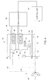
- FIG. 2 is a diagrammatical view of a fluid seal having an electromagnetic type active gap control mechanism in accordance with an exemplary embodiment of the present invention
- FIG. 3 is a diagrammatical view of a fluid seal having an electromagnetic type active gap control mechanism in accordance with an exemplary embodiment of the present invention
- FIG. 4 is a diagrammatical view of a fluid seal having an electromagnetic type active gap control mechanism in accordance with an exemplary embodiment of the present invention
- FIG. 5 is a diagrammatical view of an active gap control mechanism having a plurality of electromagnetic devices arranged along one or more radial positions in accordance with the aspects of FIG. 4;
- FIG. 6 is a diagrammatical view of an active gap control mechanism having a plurality of electromagnetic devices arranged circumferentially in accordance with the aspects of FIGS. 2 and 3;
- FIG. 7 is a diagrammatical view of an active gap control mechanism having an electromagnetic device with a single electromagnetic coil in accordance with an exemplary embodiment of the present invention
- FIG. 8 is a diagrammatical view of an active gap control mechanism having an electromagnetic device in accordance with the aspects of FIG. 7;
- FIG. 9 is a diagrammatical view of a fluid seal having an electromechanical type active gap control mechanism in accordance with an exemplary embodiment of the present invention.
- various embodiments of the present invention provide a rotary machine, in which a fluid seal is disposed between a machine rotor and a machine stator.
- the exemplary fluid seal includes a fluid seal stator, a fluid seal rotor, and an active gap control mechanism coupled to the fluid seal stator.
- the exemplary fluid seal is configured to control the flow of a sealing fluid via a gap between the fluid seal stator and the fluid seal rotor.
- the active gap control mechanism includes a plurality of electromagnetic devices coupled to the fluid seal stator.
- the active gap control mechanism includes an electromechanical device, such as a piezoelectric device or a shape memory alloy device, coupled to the fluid seal stator.
- the active gap control mechanism in accordance with the exemplary embodiments of the present invention prevents mutual contact and facilitates maintenance of a gap between fluid seal stator and the fluid seal rotor during all operating conditions of the rotary machine. Specific embodiments of the present invention are discussed below referring generally to FIGS. 1-9.
- an exemplary rotary machine (such as a turbo-compressor) 10 is illustrated in accordance with an exemplary embodiment of the present invention.
- the machine 10 includes a machine rotor 12 (such as a compressor shaft) disposed inside a machine stator 14 (sometimes referred to as a "housing").
- a fluid seal 16 is disposed between the machine rotor 12 and the machine stator 14 and configured to reduce leakage of a fluid between the machine rotor 12 and the machine stator 14.
- the fluid seal comprises a dry gas seal configured to reduce leakage of a process gas.
- a dry gas seal for ease of illustration, many examples herein reference a dry gas seal, however, the principles are applicable to liquid seals more generally.
- the process gas may include gases such as carbon dioxide, hydrogen sulfide, butane, methane, ethane, propane, liquefied natural gas, or a combination thereof.
- gases such as carbon dioxide, hydrogen sulfide, butane, methane, ethane, propane, liquefied natural gas, or a combination thereof.
- two or more dry gas seals 16 may be used, one at each end of the machine rotor 14.
- a single dry gas seal 16 located directly adjacent to an impeller may be used.
- the dry gas seal 16 includes a mating fluid seal stator 18 (non-rotatable ring) and a fluid seal rotor 20 (rotatable ring).
- the dry gas seal 16 includes the fluid seal stator 18, the fluid seal rotor 20, and a gap 22 between the fluid seal stator 18 and the fluid seal rotor 20.
- the gap 22 may be of the order of a few micrometers for example.
- the fluid seal stator 18 includes a stator member 24 disposed inside a fluid seal housing 26.
- the fluid seal rotor 20 includes a rotor member 28 disposed inside a rotor housing 30.
- the stator member 24 is axially movable within the fluid seal housing 26.
- a mechanical seal 31 (O-ring seal) is provided on a seat 32 located between the rotor member 28 and the rotor housing 30.
- the seat 32 is coupled via a spring 34 to the fluid seal housing 26.
- the spring 34 biases the stator member 24 against the rotor member 28 during non-operating conditions of the machine.
- a sealing gas (inert gas, e.g. nitrogen) enters a flow inlet path 36, flows via the gap 22 between the fluid seal stator 18 and the fluid seal rotor 20 and exits via a flow exit path 38.
- the flow of the sealing gas generates an opening force to move the stator member 24 axially within the fluid seal housing 26 and maintain the gap 22 between the fluid seal stator 18 and the fluid seal rotor 20.
- a secondary leakage of the sealing gas may occur between the stator member 24 and the fluid seal housing 26.
- the mechanical seal 31 is provided to reduce the secondary leakage of sealing gas between the stator member 24 and the fluid seal housing 26.
- a constant gap 22 is maintained between the fluid seal stator 18 and the fluid seal rotor 20.
- the constant gap 22 is maintained due to a force equilibrium between the opening force exerted on one side 40 of the stator member 24 due to the sealing gas pressure and the spring force exerted on another side 42 of the stator member 24 by the spring 34.
- the spring force acting on the side 42 of the stator member 24 becomes greater than the opening force exerted on the side 40.
- the stator member 24 contacts the rotor member 28 resulting in mechanical friction, overheating and wear of the components.
- an active gap control mechanism 44 is coupled to the fluid seal stator 18 to facilitate maintenance of gap 22 between the fluid seal rotor 20 and the fluid seal stator 18 during all operating conditions of the machine.
- the active gap control mechanism 44 is an electromagnetic device coupled to the fluid seal stator 18.
- the active gap control mechanism 44 includes an electromagnetic coil 46 coupled to the fluid seal housing 26 and an electromagnetic plunger 48 coupled to the stator member 24.
- the electromagnetic coil 46 When an electric power is supplied to the mechanism 44, the electromagnetic coil 46 generates a magnetic force that attracts the plunger 48.
- the actuation of the mechanism 44 causes the stator member 24 to be moved away from the rotor member 28.
- the gap 22 between the fluid seal stator 18 and the fluid seal rotor 20 is increased and the mechanical contact between the stator 18 and the rotor 20 is avoided.
- the stator member 24 moves towards the rotor member 28.
- the mechanism 44 further includes a micro electromechanical sensor 50 configured to detect the distance between the rotor member 28 and the stator member 24.
- sensor 50 comprises a plurality of sensors.
- the electromechanical sensor 50 is attached to the fluid seal stator 18.
- a power source 52 is coupled to the electromagnetic coil 46 and configured to supply electric power to the coil 46.
- a control unit 54 is configured to actuate the power source 52 based on an output signal from the micro electromechanical sensor 50. In other words, the control unit 54 actuates the power source 52 to control the amount of current or voltage in the electromagnetic coil 46 to control the gap between the fluid seal stator 18 and the fluid seal rotor 20.
- the control unit 54 activates the power source 52 to supply electric power to the coil 46.
- the stator member 24 is biased away from the rotor member 28 and the gap 22 is maintained between the fluid seal stator 18 and the fluid seal rotor 20.
- a second threshold limit which may be the same or different from the first threshold limit
- the control unit 54 deactivates the power source 52 to remove electric power from the coil 46.
- the stator member 24 is moved towards the rotor member 28 and the gap 22 between the fluid seal stator 18 and the fluid seal rotor 20 is reduced.
- the gap 22 is actively controlled i.e. increased or reduced to control the leakage of sealing gas.
- the gap 22 may be increased to enhance cooling of the components or reduced to prevent leakage of sealing gas depending on the requirements of the machine.
- control unit 54 may further include a database and an algorithm implemented as a computer program executed by the control unit computer or processor.
- the database may be configured to store predefined information about the rotary machine and the dry gas seal.
- the database may store information relating to type of the machine, machine speed, load, type of dry gas seal, type of sealing gas, supply pressure of sealing gas, amount of sealing gas required, gap between the fluid seal rotor and the fluid seal stator, cooling requirement, type of power source, or the like.
- the database may also include instruction sets, maps, lookup tables, variables, or the like. Such maps, lookup tables, and instruction sets, are operative to correlate characteristics of the rotary machine to control the gap between the fluid seal stator and the fluid seal rotor.
- the database may also be configured to store actual sensed/detected information pertaining to the rotary machine and the dry gas seal.
- the algorithm may facilitate the processing of sensed information pertaining to the rotary machine and the dry gas seal. Any of the above mentioned parameters may be selectively and/or dynamically adapted or altered relative to time. For example, the gap between fluid seal rotor and the fluid seal stator may be altered depending on the speed or load of the machine. In another example, the gap may be altered depending on the cooling requirement. In yet another example, the gap may be altered depending on the sealing gas consumption. Similarly, any number of examples may be envisaged.
- the gap control mechanism 44 includes a plurality electromagnetic coils 46 coupled to the fluid seal housing 26 and a plurality of electromagnetic plungers 48 coupled to the stator member 24.
- the plungers 48 may be configured facing the coils 46.
- the electromagnetic coils 46 When an electric power is supplied to the mechanism 44, the electromagnetic coils 46 generates a magnetic force that attracts the plungers 48. The actuation of the mechanism 44 causes the stator member 24 to be moved away from the rotor member 28. As a result, the gap 22 between the fluid seal stator 18 and the fluid seal rotor 20 is increased and the mechanical contact between the stator 18 and the rotor 20 is avoided.
- the active gap control mechanism 44 in accordance with the aspects of FIG. 4.
- the plurality of electromagnetic coils 46 are arranged along one or more radial positions along the fluid seal housing 26.
- the plurality of electromagnetic plungers 48 are arranged along one or more radial positions along the stator member. Each plunger 48 is located facing the corresponding electromagnetic coil 46. It should be noted herein that any number of arrangement patterns of the coils 46 and plungers 48 are envisioned.
- the active gap control mechanism 44 in accordance with the aspects of FIGS 2 and 3.
- the stator member 24 (illustrated in FIGS. 2 and 3) is provided inside the fluid seal housing 26.
- the plurality of electromagnetic coils 46 are evenly spaced apart and provided around the circumference of the fluid seal housing 26.
- the plurality of electromagnetic plungers 48 are evenly spaced apart and provided around the circumference of the stator member. Each plunger 48 is located facing the corresponding electromagnetic coil 46. In certain other exemplary embodiments, the coils 46 and the plungers 48 are randomly spaced around the circumference of the fluid seal housing 26.
- the active gap control mechanism 44 in accordance with another exemplary embodiment of the present invention is illustrated.
- the active gap control mechanism 44 is coupled to the fluid seal stator 18.
- the active gap control mechanism 44 includes one electromagnetic coil 46 wound fully around the fluid seal housing 26.
- the electromagnetic plunger 48 is coupled to the stator member 24 and located facing the coil 46. When an electric power is supplied to the mechanism 44, the electromagnetic coil 46 generates a magnetic force that attracts the plunger. The actuation of the mechanism 44 causes the stator member 24 to be moved away from the rotor member.
- FIG. 8 is a diagrammatical view of an active gap control mechanism 44 in accordance with the aspects of FIG. 7.
- the active gap control mechanism 44 includes one electromagnetic coil 46 wound fully around the fluid seal housing 26.
- the electromagnetic plunger 48 is coupled to the stator member 24 and located facing the coil 46.
- the dry gas seal 16 having the gap control mechanism 44 in accordance with an exemplary embodiment of the present invention is illustrated.
- the mechanism 44 includes an electromechanical device 56 which is illustrated as being coupled to the fluid seal housing 26.
- the electromechanical device 56 is coupled to stator member 24.
- the electromechanical device 56 is a piezo electrical device.
- the piezo electrical device 56 includes a piezo electrical crystal that changes dimensions upon supply of electrical current or voltage to the device 56. Although one piezo electrical device 56 is illustrated, a plurality of devices 56 may be used in other exemplary embodiments.
- the piezo electrical device 56 actuates the stator member 24 in such a way so as to move stator member 24 away from the rotor member 28.
- the gap 22 between the fluid seal stator 18 and the fluid seal rotor 20 is increased and the mechanical contact between the stator 18 and the rotor 20 is avoided.
- the control unit 54 actuates the power source 52 to control the amount of current or voltage in the piezo electrical device 56 to control the gap between the fluid seal stator 18 and the fluid seal rotor 20.
- the control unit 54 selectively activates the power source 52 to supply electric power to the piezo electrical device 56 and bias the stator member 24 away from the rotor member 28 and the gap 22 is maintained between the fluid seal stator 18 and the fluid seal rotor 20 is increased.
- the control unit 54 selectively deactivates the power source 52 to remove electric power from the piezo electrical device 56 and move the stator member 24 towards the rotor member 28.
- the control unit 54 and the micro electromechanical sensor 50 may not be required to actuate the gap control mechanism 44.
- the electromechanical device 56 is a shape memory alloy device.
- the shape memory alloy device includes a plurality of wires that produce movement when an electric current is passed through the wires.
- the wires may include alloys of copper, nickel, aluminum, or copper, zinc, aluminum, or iron, silicon, manganese, or nickel, titanium, and carbon (nitinol).
- the wires are cooled below a transition temperature, the wires are converted to martensite phase and are deformable.
- the wires are heated above the transition temperature, the wires are converted to austenite phase resulting in restoration of the original shape of the wires.
- a plurality of shape memory alloy devices may be used.
- the shape memory alloy device When an electric power is supplied to the mechanism 44, the shape memory alloy device actuates the stator member 24 in such a way so as to move stator member 24 away from the rotor member 28. As a result, the gap 22 between the fluid seal stator 18 and the fluid seal rotor 20 is increased and the mechanical contact between the stator 18 and the rotor 20 is avoided.
- the control unit 54 actuates the power source 52 to control the amount of current and subsequently temperature in the shape memory alloy device to control the gap between the fluid seal stator 18 and the fluid seal rotor 20.
- the active gap control mechanism in accordance with the exemplary embodiments of the present invention prevents mutual contact and facilitates maintenance of a gap between the fluid seal stator and the fluid seal rotor during all operating conditions of the rotary machine.
Landscapes
- Engineering & Computer Science (AREA)
- General Engineering & Computer Science (AREA)
- Mechanical Engineering (AREA)
- Structures Of Non-Positive Displacement Pumps (AREA)
- Sealing Using Fluids, Sealing Without Contact, And Removal Of Oil (AREA)
- Other Liquid Machine Or Engine Such As Wave Power Use (AREA)
- Auxiliary Devices For And Details Of Packaging Control (AREA)
- Encapsulation Of And Coatings For Semiconductor Or Solid State Devices (AREA)
- Mechanical Sealing (AREA)
Abstract
Description
- The invention relates generally to a rotary machine and, more particularly, to a sealing system for an interface between rotating and stationary components. In certain aspects, the sealing system includes a mechanical sealing system between a rotary shaft and a surrounding structure of turbo-compressors.
- Performance and efficiency of rotary machines, e.g., turbo-compressors, are dependent on a clearance gap between rotating and stationary components within the turbine engine. For example, the clearance gap between the rotary shaft and the surrounding stationary housing provides a narrow flow passage, resulting in process fluid flow leakage that can reduce the rotary machine performance. As the gap between the rotating and the stationary components increases, the leakage flow increases and the efficiency of the machine decreases.
- Dry gas seals are used in rotary machines such as turbo-compressors to seal leakage of a process gas between the rotating and stationary components. Dry gas seals are basically mechanical face seals, consisting of a mating (rotating) and a primary (stationary) ring. During operation, grooves in the rotating ring generate a fluid-dynamic force causing the stationary ring to separate from the rotating ring creating a "running gap" between the two rings. A sealing gas flows via the gap between the rotating and stationary rings. However, during stand-still and lower operating speeds of the rotary machines, flow of sealing gas via the gap between the rotating and stationary rings is reduced. The rotating and stationary rings mutually contact each other and cause mechanical friction, wear, and overheating.
- In certain examples, actuator devices such as auxiliary pumps may be used to supply pressure to open the gap between the rotating and stationary rings and therefore avoid contact during stand-still and lower speed operating conditions. Flow of less sealing gas via the gap between the rotating and stationary rings causes over heating of the mechanical parts of the seal which eventually results in seal damage. Flow of excess sealing gas via the gap between the rotating and stationary rings results in high seal gas consumption and reduction in efficiency of the machine.
- Accordingly, there is a need for a system and method for maintaining minimum contact force between rotating and stationary parts of a sealing system during transitional operating conditions of the rotary machine.
- In accordance with one exemplary embodiment of the present invention, a rotary machine includes a machine rotor, a machine stator, and a fluid seal disposed between the machine rotor and the machine stator. The fluid seal includes a fluid seal stator, a fluid seal rotor, and a gap control mechanism coupled to the fluid seal stator, and configured to control a gap between the fluid seal stator and the fluid seal rotor.
- In accordance with another exemplary embodiment of the present invention, a fluid sealing device includes a fluid seal stator, a fluid seal rotor, and an active gap control mechanism coupled to the fluid seal stator, and configured to control a gap between the fluid seal stator and the fluid seal rotor.
- In accordance with another exemplary embodiment of the present invention, a method of operating a rotary machine includes actively controlling a gap between the fluid seal stator and the fluid seal rotor.
- Various features, aspects, and advantages of the present invention will become better understood when the following detailed description is read with reference to the accompanying drawings in which like characters represent like parts throughout the drawings, wherein:
- FIG. 1 is a partial perspective view of rotary machine, which for purposes of example is illustrated as a turbo-compressor, having a fluid seal in accordance with an exemplary embodiment of the present invention;
- FIG. 2 is a diagrammatical view of a fluid seal having an electromagnetic type active gap control mechanism in accordance with an exemplary embodiment of the present invention;
- FIG. 3 is a diagrammatical view of a fluid seal having an electromagnetic type active gap control mechanism in accordance with an exemplary embodiment of the present invention;
- FIG. 4 is a diagrammatical view of a fluid seal having an electromagnetic type active gap control mechanism in accordance with an exemplary embodiment of the present invention;
- FIG. 5 is a diagrammatical view of an active gap control mechanism having a plurality of electromagnetic devices arranged along one or more radial positions in accordance with the aspects of FIG. 4;
- FIG. 6 is a diagrammatical view of an active gap control mechanism having a plurality of electromagnetic devices arranged circumferentially in accordance with the aspects of FIGS. 2 and 3;
- FIG. 7 is a diagrammatical view of an active gap control mechanism having an electromagnetic device with a single electromagnetic coil in accordance with an exemplary embodiment of the present invention;
- FIG. 8 is a diagrammatical view of an active gap control mechanism having an electromagnetic device in accordance with the aspects of FIG. 7; and
- FIG. 9 is a diagrammatical view of a fluid seal having an electromechanical type active gap control mechanism in accordance with an exemplary embodiment of the present invention.
- As discussed in detail below, various embodiments of the present invention provide a rotary machine, in which a fluid seal is disposed between a machine rotor and a machine stator. The exemplary fluid seal includes a fluid seal stator, a fluid seal rotor, and an active gap control mechanism coupled to the fluid seal stator. The exemplary fluid seal is configured to control the flow of a sealing fluid via a gap between the fluid seal stator and the fluid seal rotor. In one exemplary embodiment, the active gap control mechanism includes a plurality of electromagnetic devices coupled to the fluid seal stator. In another exemplary embodiment, the active gap control mechanism includes an electromechanical device, such as a piezoelectric device or a shape memory alloy device, coupled to the fluid seal stator. The active gap control mechanism in accordance with the exemplary embodiments of the present invention prevents mutual contact and facilitates maintenance of a gap between fluid seal stator and the fluid seal rotor during all operating conditions of the rotary machine. Specific embodiments of the present invention are discussed below referring generally to FIGS. 1-9.
- Referring to FIG. 1, an exemplary rotary machine (such as a turbo-compressor) 10 is illustrated in accordance with an exemplary embodiment of the present invention. The
machine 10 includes a machine rotor 12 (such as a compressor shaft) disposed inside a machine stator 14 (sometimes referred to as a "housing"). Afluid seal 16 is disposed between themachine rotor 12 and themachine stator 14 and configured to reduce leakage of a fluid between themachine rotor 12 and themachine stator 14. In one embodiment, the fluid seal comprises a dry gas seal configured to reduce leakage of a process gas. For ease of illustration, many examples herein reference a dry gas seal, however, the principles are applicable to liquid seals more generally. The process gas may include gases such as carbon dioxide, hydrogen sulfide, butane, methane, ethane, propane, liquefied natural gas, or a combination thereof. In certain embodiments, two or moredry gas seals 16 may be used, one at each end of themachine rotor 14. In certain other embodiments, a singledry gas seal 16 located directly adjacent to an impeller (not shown) may be used. Thedry gas seal 16 includes a mating fluid seal stator 18 (non-rotatable ring) and a fluid seal rotor 20 (rotatable ring). During operation of the machine, grooves (not shown) in thefluid seal stator 18 and thefluid seal rotor 20 generate a fluid-dynamic force causing thefluid seal stator 18 to separate from thefluid seal rotor 20 creating a "running gap" between thefluid seal stator 18 and thefluid seal rotor 20. It should be noted herein that the illustrated turbo-compressor is merely an exemplary embodiment, and the dry gas seal in accordance with the embodiment of the present invention may also be applicable to other rotary machines requiring sealing arrangements to prevent leakage of sealing gas. The details and operation of thedry gas seal 16 is explained in greater detail with respect to subsequent figures. - Referring to FIG. 2, a detailed view of the
dry gas seal 16 in accordance with certain exemplary embodiments of the present invention is illustrated. As discussed above, thedry gas seal 16 includes thefluid seal stator 18, thefluid seal rotor 20, and agap 22 between thefluid seal stator 18 and thefluid seal rotor 20. Thegap 22 may be of the order of a few micrometers for example. Thefluid seal stator 18 includes astator member 24 disposed inside afluid seal housing 26. Thefluid seal rotor 20 includes arotor member 28 disposed inside arotor housing 30. Thestator member 24 is axially movable within thefluid seal housing 26. A mechanical seal 31 (O-ring seal) is provided on aseat 32 located between therotor member 28 and therotor housing 30. Theseat 32 is coupled via aspring 34 to thefluid seal housing 26. Thespring 34 biases thestator member 24 against therotor member 28 during non-operating conditions of the machine. - During operation conditions of the
dry gas seal 16, a sealing gas (inert gas, e.g. nitrogen) enters aflow inlet path 36, flows via thegap 22 between thefluid seal stator 18 and thefluid seal rotor 20 and exits via aflow exit path 38. The flow of the sealing gas generates an opening force to move thestator member 24 axially within thefluid seal housing 26 and maintain thegap 22 between thefluid seal stator 18 and thefluid seal rotor 20. A secondary leakage of the sealing gas may occur between thestator member 24 and the fluid seal housing 26. Themechanical seal 31 is provided to reduce the secondary leakage of sealing gas between thestator member 24 and thefluid seal housing 26. - During normal operating conditions of the machine (i.e., wherein the machine is operating at nominal speeds and under nominal values of supply pressure of the sealing gas) a
constant gap 22 is maintained between thefluid seal stator 18 and thefluid seal rotor 20. Theconstant gap 22 is maintained due to a force equilibrium between the opening force exerted on oneside 40 of thestator member 24 due to the sealing gas pressure and the spring force exerted on anotherside 42 of thestator member 24 by thespring 34. During lower operating speeds of the machine, the spring force acting on theside 42 of thestator member 24 becomes greater than the opening force exerted on theside 40. As a result, thestator member 24 contacts therotor member 28 resulting in mechanical friction, overheating and wear of the components. If less sealing gas flows via thegap 22, the mutually contacting components overheat. If excess sealing gas flows via thegap 22, consumption of sealing gas increases. In the illustrated embodiment, an activegap control mechanism 44 is coupled to thefluid seal stator 18 to facilitate maintenance ofgap 22 between thefluid seal rotor 20 and thefluid seal stator 18 during all operating conditions of the machine. - In the illustrated embodiment, the active
gap control mechanism 44 is an electromagnetic device coupled to thefluid seal stator 18. The activegap control mechanism 44 includes anelectromagnetic coil 46 coupled to thefluid seal housing 26 and anelectromagnetic plunger 48 coupled to thestator member 24. When an electric power is supplied to themechanism 44, theelectromagnetic coil 46 generates a magnetic force that attracts theplunger 48. The actuation of themechanism 44 causes thestator member 24 to be moved away from therotor member 28. As a result, thegap 22 between thefluid seal stator 18 and thefluid seal rotor 20 is increased and the mechanical contact between thestator 18 and therotor 20 is avoided. When electric power is reduced or removed from themechanism 44, thestator member 24 moves towards therotor member 28. - Referring to FIG. 3, the
dry gas seal 16 having the activegap control mechanism 44 in accordance with the aspects of FIG. 2 is illustrated. In one embodiment themechanism 44 further includes a microelectromechanical sensor 50 configured to detect the distance between therotor member 28 and thestator member 24. In some embodiments,sensor 50 comprises a plurality of sensors. In the embodiment of Fig. 3, theelectromechanical sensor 50 is attached to thefluid seal stator 18. Apower source 52 is coupled to theelectromagnetic coil 46 and configured to supply electric power to thecoil 46. Acontrol unit 54 is configured to actuate thepower source 52 based on an output signal from the microelectromechanical sensor 50. In other words, thecontrol unit 54 actuates thepower source 52 to control the amount of current or voltage in theelectromagnetic coil 46 to control the gap between thefluid seal stator 18 and thefluid seal rotor 20. - In one example, when the distance between the
stator member 24 and therotor member 28 is less than a first threshold limit, thecontrol unit 54 activates thepower source 52 to supply electric power to thecoil 46. As a result, thestator member 24 is biased away from therotor member 28 and thegap 22 is maintained between thefluid seal stator 18 and thefluid seal rotor 20. When the distance between thestator member 24 and therotor member 28 is greater than a second threshold limit (which may be the same or different from the first threshold limit), thecontrol unit 54 deactivates thepower source 52 to remove electric power from thecoil 46. As a result, thestator member 24 is moved towards therotor member 28 and thegap 22 between thefluid seal stator 18 and thefluid seal rotor 20 is reduced. In the illustrated embodiment of FIG. 3, thegap 22 is actively controlled i.e. increased or reduced to control the leakage of sealing gas. Thegap 22 may be increased to enhance cooling of the components or reduced to prevent leakage of sealing gas depending on the requirements of the machine. - In certain embodiments, the
control unit 54 may further include a database and an algorithm implemented as a computer program executed by the control unit computer or processor. The database may be configured to store predefined information about the rotary machine and the dry gas seal. For example, the database may store information relating to type of the machine, machine speed, load, type of dry gas seal, type of sealing gas, supply pressure of sealing gas, amount of sealing gas required, gap between the fluid seal rotor and the fluid seal stator, cooling requirement, type of power source, or the like. The database may also include instruction sets, maps, lookup tables, variables, or the like. Such maps, lookup tables, and instruction sets, are operative to correlate characteristics of the rotary machine to control the gap between the fluid seal stator and the fluid seal rotor. The database may also be configured to store actual sensed/detected information pertaining to the rotary machine and the dry gas seal. The algorithm may facilitate the processing of sensed information pertaining to the rotary machine and the dry gas seal. Any of the above mentioned parameters may be selectively and/or dynamically adapted or altered relative to time. For example, the gap between fluid seal rotor and the fluid seal stator may be altered depending on the speed or load of the machine. In another example, the gap may be altered depending on the cooling requirement. In yet another example, the gap may be altered depending on the sealing gas consumption. Similarly, any number of examples may be envisaged. - Referring to FIG. 4, the
dry gas seal 16 having the activegap control mechanism 44 in accordance with an exemplary embodiment of the present invention is illustrated. Thegap control mechanism 44 includes a pluralityelectromagnetic coils 46 coupled to thefluid seal housing 26 and a plurality ofelectromagnetic plungers 48 coupled to thestator member 24. Theplungers 48 may be configured facing thecoils 46. - When an electric power is supplied to the
mechanism 44, theelectromagnetic coils 46 generates a magnetic force that attracts theplungers 48. The actuation of themechanism 44 causes thestator member 24 to be moved away from therotor member 28. As a result, thegap 22 between thefluid seal stator 18 and thefluid seal rotor 20 is increased and the mechanical contact between thestator 18 and therotor 20 is avoided. - Referring to FIG. 5, the active
gap control mechanism 44 in accordance with the aspects of FIG. 4. In the illustrated embodiment, the plurality ofelectromagnetic coils 46 are arranged along one or more radial positions along thefluid seal housing 26. Similarly, the plurality ofelectromagnetic plungers 48 are arranged along one or more radial positions along the stator member. Eachplunger 48 is located facing the correspondingelectromagnetic coil 46. It should be noted herein that any number of arrangement patterns of thecoils 46 andplungers 48 are envisioned. - Referring to FIG. 6, the active
gap control mechanism 44 in accordance with the aspects of FIGS 2 and 3. As discussed previously, the stator member 24 (illustrated in FIGS. 2 and 3) is provided inside thefluid seal housing 26. The plurality ofelectromagnetic coils 46 are evenly spaced apart and provided around the circumference of thefluid seal housing 26. The plurality ofelectromagnetic plungers 48 are evenly spaced apart and provided around the circumference of the stator member. Eachplunger 48 is located facing the correspondingelectromagnetic coil 46. In certain other exemplary embodiments, thecoils 46 and theplungers 48 are randomly spaced around the circumference of thefluid seal housing 26. - Referring to FIG. 7, the active
gap control mechanism 44 in accordance with another exemplary embodiment of the present invention is illustrated. In the illustrated embodiment, the activegap control mechanism 44 is coupled to thefluid seal stator 18. The activegap control mechanism 44 includes oneelectromagnetic coil 46 wound fully around thefluid seal housing 26. Theelectromagnetic plunger 48 is coupled to thestator member 24 and located facing thecoil 46. When an electric power is supplied to themechanism 44, theelectromagnetic coil 46 generates a magnetic force that attracts the plunger. The actuation of themechanism 44 causes thestator member 24 to be moved away from the rotor member. - FIG. 8 is a diagrammatical view of an active
gap control mechanism 44 in accordance with the aspects of FIG. 7. The activegap control mechanism 44 includes oneelectromagnetic coil 46 wound fully around thefluid seal housing 26. Theelectromagnetic plunger 48 is coupled to thestator member 24 and located facing thecoil 46. - Referring to FIG. 9, the
dry gas seal 16 having thegap control mechanism 44 in accordance with an exemplary embodiment of the present invention is illustrated. In an embodiment wherein themechanism 44 includes anelectromechanical device 56 which is illustrated as being coupled to thefluid seal housing 26. In an alternative embodiment, theelectromechanical device 56 is coupled tostator member 24. In one embodiment, theelectromechanical device 56 is a piezo electrical device. The piezoelectrical device 56 includes a piezo electrical crystal that changes dimensions upon supply of electrical current or voltage to thedevice 56. Although one piezoelectrical device 56 is illustrated, a plurality ofdevices 56 may be used in other exemplary embodiments. When an electric power is supplied to themechanism 44, the piezoelectrical device 56 actuates thestator member 24 in such a way so as to movestator member 24 away from therotor member 28. As a result, thegap 22 between thefluid seal stator 18 and thefluid seal rotor 20 is increased and the mechanical contact between thestator 18 and therotor 20 is avoided. - The
control unit 54 actuates thepower source 52 to control the amount of current or voltage in the piezoelectrical device 56 to control the gap between thefluid seal stator 18 and thefluid seal rotor 20. In a similar manner as discussed above with respect to FIG. 3, thecontrol unit 54 selectively activates thepower source 52 to supply electric power to the piezoelectrical device 56 and bias thestator member 24 away from therotor member 28 and thegap 22 is maintained between thefluid seal stator 18 and thefluid seal rotor 20 is increased. Thecontrol unit 54 selectively deactivates thepower source 52 to remove electric power from the piezoelectrical device 56 and move thestator member 24 towards therotor member 28. In certain other exemplary embodiment, thecontrol unit 54 and the microelectromechanical sensor 50 may not be required to actuate thegap control mechanism 44. - In another exemplary embodiment, the
electromechanical device 56 is a shape memory alloy device. In certain embodiments, the shape memory alloy device includes a plurality of wires that produce movement when an electric current is passed through the wires. The wires may include alloys of copper, nickel, aluminum, or copper, zinc, aluminum, or iron, silicon, manganese, or nickel, titanium, and carbon (nitinol). When the wires are cooled below a transition temperature, the wires are converted to martensite phase and are deformable. When the wires are heated above the transition temperature, the wires are converted to austenite phase resulting in restoration of the original shape of the wires. In certain exemplary embodiments, a plurality of shape memory alloy devices may be used. - When an electric power is supplied to the
mechanism 44, the shape memory alloy device actuates thestator member 24 in such a way so as to movestator member 24 away from therotor member 28. As a result, thegap 22 between thefluid seal stator 18 and thefluid seal rotor 20 is increased and the mechanical contact between thestator 18 and therotor 20 is avoided. Thecontrol unit 54 actuates thepower source 52 to control the amount of current and subsequently temperature in the shape memory alloy device to control the gap between thefluid seal stator 18 and thefluid seal rotor 20. The active gap control mechanism in accordance with the exemplary embodiments of the present invention prevents mutual contact and facilitates maintenance of a gap between the fluid seal stator and the fluid seal rotor during all operating conditions of the rotary machine. - While only certain features of the invention have been illustrated and described herein, many modifications and changes will occur to those skilled in the art. It is, therefore, to be understood that the appended claims are intended to cover all such modifications and changes as fall within the true spirit of the invention.
Claims (10)
- A rotary machine (10), comprising:a machine rotor (12);a machine stator (14); anda fluid seal (16) disposed between the machine rotor (12) and the machine stator (14); comprising:a fluid seal stator (18),a fluid seal rotor (20), andan active gap control mechanism (44) coupled to the fluid seal stator (18), and configured to control a gap (22) between the fluid seal stator (18) and the fluid seal rotor (20).
- The rotary machine (10) of claim 1, wherein the fluid seal stator (18) comprises a stator member (24) configured to move axially within a fluid seal housing (26).
- The rotary machine (10) of claim 2, wherein the active gap control mechanism (44) comprises at least one electromagnetic coil (46) coupled to the fluid seal housing (26) and at least one electromagnetic plunger (48) coupled to the stator member (24), wherein the at least one electromagnetic coil (46) and the at least one electromagnetic plunger (48) are configured to bias the stator member (24) towards or away from the fluid seal rotor (20) upon supply of current to the electromagnetic coil (46).
- The rotary machine (10) of claim 3, further comprising a control unit (54) for controlling the amount of current in the electromagnetic coil (46) in order to control the gap (22) between the stator member (24) and the fluid seal rotor (20).
- The rotary machine (10) of claim 2 or any claim dependent thereon, wherein the active gap control mechanism (44) comprises one or more piezo electrical device (56) coupled to the fluid seal housing (26) and configured to bias the stator member (24) towards or away from the fluid seal rotor (20) upon supply of voltage to the piezo electrical device (56).
- The rotary machine (10) of claim 5, further comprising a control unit (54) for controlling the amount of voltage in the piezo electrical device (56) in order control the gap (22) between the stator member (24) and the fluid seal rotor (20).
- The rotary machine (10) of claim 2 or any claim dependent thereon, wherein the active gap control mechanism (44) comprises one or more shape memory alloy devices (56) coupled to the fluid seal housing (26) and configured to bias the stator member (24) towards or away from the fluid seal rotor (20) upon supply of current to the shape memory alloy device (56).
- The rotary machine (10) of claim 2 or any claim dependent thereon, wherein the active gap control mechanism (44) comprises at least one micro electromechanical sensor (50) configured to detect a distance between the fluid seal rotor (20) and the fluid seal stator (18).
- A method of operating a rotary machine (10) comprising a machine rotor (12); a machine stator (14); and a fluid seal (16) disposed between the machine rotor (12) and the machine stator (14) and comprising a fluid seal stator (18) and a fluid seal rotor (20), the method comprising:actively controlling a flow of a sealing fluid via a gap (22) between the fluid seal stator (18) and the fluid seal rotor (20).
- The method of claim 9, wherein actively controlling comprises actuating an electromagnetic device, a piezoelectric device, a shape memory alloy device, or combinations thereof to bias the fluid seal stator (18) away from the fluid seal rotor (20) during lower operating speeds of the rotary machine (10).
Priority Applications (2)
| Application Number | Priority Date | Filing Date | Title |
|---|---|---|---|
| SI200730564T SI1918618T1 (en) | 2006-11-03 | 2007-11-02 | Mechanical sealing system and method for rotary machines |
| PL07119880T PL1918618T3 (en) | 2006-11-03 | 2007-11-02 | Mechanical sealing system and method for rotary machines |
Applications Claiming Priority (1)
| Application Number | Priority Date | Filing Date | Title |
|---|---|---|---|
| US55629406A | 2006-11-03 | 2006-11-03 |
Publications (2)
| Publication Number | Publication Date |
|---|---|
| EP1918618A1 true EP1918618A1 (en) | 2008-05-07 |
| EP1918618B1 EP1918618B1 (en) | 2011-01-12 |
Family
ID=38950770
Family Applications (1)
| Application Number | Title | Priority Date | Filing Date |
|---|---|---|---|
| EP07119880A Not-in-force EP1918618B1 (en) | 2006-11-03 | 2007-11-02 | Mechanical sealing system and method for rotary machines |
Country Status (14)
| Country | Link |
|---|---|
| US (1) | US20100072706A1 (en) |
| EP (1) | EP1918618B1 (en) |
| JP (1) | JP2008116049A (en) |
| KR (1) | KR20080040589A (en) |
| CN (1) | CN101260941B (en) |
| AT (1) | ATE495397T1 (en) |
| CA (1) | CA2607700A1 (en) |
| DE (1) | DE602007011863D1 (en) |
| DK (1) | DK1918618T3 (en) |
| ES (1) | ES2357142T3 (en) |
| PL (1) | PL1918618T3 (en) |
| PT (1) | PT1918618E (en) |
| RU (1) | RU2454584C2 (en) |
| SI (1) | SI1918618T1 (en) |
Cited By (3)
| Publication number | Priority date | Publication date | Assignee | Title |
|---|---|---|---|---|
| WO2014152999A1 (en) * | 2013-03-14 | 2014-09-25 | Georgia Tech Research Corporation | Hydraulically controllable mechanical seal |
| WO2015003818A3 (en) * | 2013-07-11 | 2015-07-02 | Wilhelm Brinkmann | Rotary internal combustion engine with active seals |
| CN109790929A (en) * | 2016-06-10 | 2019-05-21 | 约翰起重机英国有限公司 | With the electronically controlled dry gas seals for closing valve |
Families Citing this family (27)
| Publication number | Priority date | Publication date | Assignee | Title |
|---|---|---|---|---|
| WO2010116462A1 (en) * | 2009-03-30 | 2010-10-14 | 富士通オプティカルコンポーネンツ株式会社 | Communication module |
| CN102261476A (en) * | 2011-06-02 | 2011-11-30 | 温州市天成密封件制造有限公司 | Flexible seal system |
| US20130134679A1 (en) * | 2011-11-30 | 2013-05-30 | General Electric Company | Non-contacting seal arrangement, electromechanical system having a non-contacting seal arrangement, and method of fabricating a non-contacting seal arrangement |
| US9991771B2 (en) * | 2013-11-05 | 2018-06-05 | The University Of Maryland, Baltimore County | Active control system for a variable electromotive-force generator with applications to wind turbines, ships, and hybrid vehicles |
| US9919808B2 (en) | 2015-06-01 | 2018-03-20 | Parker-Hannifin Corporation | Piezoelectrically-controlled fuel delivery system |
| EP3334962B1 (en) * | 2015-08-10 | 2019-09-18 | Exxonmobil Upstream Research Company | Device and method for magnetically controlled dry gas seal |
| JP6503144B2 (en) * | 2015-11-30 | 2019-04-17 | ブルクハルト コンプレッション アーゲー | Dry run piston rod packing and method for operating dry run piston rod packing |
| BR122023003434B1 (en) | 2016-02-23 | 2024-01-30 | John Crane Uk Ltd | MECHANICAL SEAL SYSTEM CONFIGURED TO AUTONOMOUSLY DETECT A LOSS OF LUBRICATION WITHIN A SLIDING SEAL INTERFACE OF A MECHANICAL SEAL, MECHANICAL SEAL SYSTEM THAT HAS A CUSTOMIZABLE PREDICTIVE DIAGNOSTIC SUBSYSTEM CONFIGURED TO BE ADAPTED TO SUIT YOUR NEEDS INDIVIDUAL CUSTOMER AGES, CONDITIONS PARTICULAR ENVIRONMENTAL AND/OR APPLICATION SPECIFIC, AND MECHANICAL SEALING SYSTEM CONFIGURED TO DETECT OPERATING CONDITIONS AND PROVIDE REAL-TIME INTEGRITY ASSESSMENTS TO A USER DURING OPERATION |
| US10119616B2 (en) * | 2016-04-08 | 2018-11-06 | Chevron U.S.A. Inc. | Mechanical seal assistance device and systems and methods for use thereof |
| US20170314683A1 (en) * | 2016-05-02 | 2017-11-02 | GM Global Technology Operations LLC | Seal assembly |
| US10132412B2 (en) | 2016-08-05 | 2018-11-20 | Exxonmobil Upstream Research Company | Device and method for controlling rotating equipment seal without buffer support equipment |
| CN106499824B (en) * | 2017-01-09 | 2018-08-10 | 昆明理工大学 | A kind of reciprocating magnetic liquid self-circulation lubricating sealing device |
| WO2018213313A1 (en) | 2017-05-15 | 2018-11-22 | John Crane Uk Ltd. | Dry gas seal with electronically controlled carrier load |
| CN107269848B (en) * | 2017-07-06 | 2018-10-23 | 浙江工业大学 | Foil end face air film sealing structure based on magnetic control shape memory effect |
| CN107939722B (en) * | 2017-11-30 | 2024-02-09 | 北京航天动力研究所 | Spring-loaded automatic release type dynamic sealing device for oxyhydrogen engine turbopump |
| GB2596406B (en) * | 2018-10-08 | 2022-08-17 | Crane John Uk Ltd | Mechanical seal with sensor |
| US11280761B2 (en) * | 2018-10-08 | 2022-03-22 | John Crane Uk Limited | Mechanical seal with sensor |
| DE102018125969A1 (en) * | 2018-10-18 | 2020-04-23 | Herborner Pumpentechnik Gmbh & Co Kg | Mechanical seal device with microsystem, pump device herewith and method for its operation |
| CN110056535B (en) * | 2019-05-27 | 2020-09-11 | 新乡市中机工业有限公司 | A wear-resistant and corrosion-resistant mouth ring device for a water pump |
| CN111577400B (en) * | 2020-04-29 | 2024-08-09 | 中国核动力研究设计院 | Supercritical carbon dioxide turbine shaft end sealing method and device for dry gas coupling labyrinth seal |
| DE102020124238A1 (en) * | 2020-09-17 | 2022-03-17 | Eagleburgmann Germany Gmbh & Co. Kg | Method for operating a mechanical seal assembly and mechanical seal assembly |
| CN112303239B (en) * | 2020-10-28 | 2022-10-04 | 中国计量大学 | Active dynamic pressure type gas film end face sealing device and intelligent control method thereof |
| CN112645197B (en) * | 2020-11-27 | 2022-06-14 | 日立电梯(中国)有限公司 | An easy-to-control anti-foaming water reverse rope pulley |
| CN113027808B (en) * | 2021-05-13 | 2022-12-20 | 毅飞泵业(福州)有限公司 | Centrifugal pump |
| CN113324039B (en) * | 2021-05-17 | 2022-03-11 | 清华大学 | Method for reducing starting torque of magnetic liquid sealing device |
| CN114623239B (en) * | 2022-03-18 | 2023-08-25 | 清华大学 | Mechanical seal and its adjustment method for the degree of deformation of the sealing end face |
| CN116123288A (en) * | 2023-02-17 | 2023-05-16 | 清华大学 | Measurement and control integrated mechanical sealing device |
Citations (5)
| Publication number | Priority date | Publication date | Assignee | Title |
|---|---|---|---|---|
| US4424975A (en) * | 1983-04-25 | 1984-01-10 | The United States Of America As Represented By The United States Department Of Energy | Rotary shaft seal |
| US4434987A (en) * | 1982-06-25 | 1984-03-06 | M.A.N. Maschinenfabrik Augsburg-Nurnberg Aktiengesellschaft | Shaft seal with magnetically controlled gap between rotating ring and surrounding non-rotating ring |
| US4447063A (en) * | 1982-06-05 | 1984-05-08 | M.A.N. Maschinenfabrik Augsburg-Nurnberg A.G. | Shaft seal with positively magnetically controlled sealing gap |
| US4643437A (en) * | 1985-10-21 | 1987-02-17 | Borg-Warner Industrial Products, Inc. | Mechanical seal with automatic gap convergence control |
| JPS62261764A (en) | 1986-05-06 | 1987-11-13 | Toshiba Corp | Shaft seal device |
Family Cites Families (33)
| Publication number | Priority date | Publication date | Assignee | Title |
|---|---|---|---|---|
| US4515213A (en) * | 1983-02-09 | 1985-05-07 | Memory Metals, Inc. | Packing tool apparatus for sealing well bores |
| JPS61157751U (en) * | 1985-03-25 | 1986-09-30 | ||
| US4691276A (en) * | 1985-10-21 | 1987-09-01 | Borg-Warner Industrial Products, Inc. | Adaptive control system for mechanical seal assembly |
| JPH0624613Y2 (en) * | 1988-09-09 | 1994-06-29 | 三菱重工業株式会社 | mechanical seal |
| US5000463A (en) * | 1989-10-10 | 1991-03-19 | Hughes Aircraft Company | Shaft seal for systems with intermittent operation |
| JPH0372157U (en) * | 1989-11-15 | 1991-07-22 | ||
| US5064205A (en) * | 1990-05-23 | 1991-11-12 | General Electric Company | Active magnetic seal |
| US5603510A (en) * | 1991-06-13 | 1997-02-18 | Sanders; William P. | Variable clearance seal assembly |
| US5199497A (en) * | 1992-02-14 | 1993-04-06 | Baker Hughes Incorporated | Shape-memory actuator for use in subterranean wells |
| US5238308A (en) * | 1992-05-04 | 1993-08-24 | Rockwell International Corporation | Adjustable gap hydrostatic element |
| JPH08121612A (en) * | 1994-10-26 | 1996-05-17 | Mitsubishi Heavy Ind Ltd | Non-contact sealing device |
| US5762342A (en) * | 1996-05-03 | 1998-06-09 | Durametallic Corporation | Mechanical seal with controller for regulating face contact pressure |
| US5979828A (en) * | 1997-04-30 | 1999-11-09 | Mcdonnell Douglas | Apparatus for eliminating gaps in an aircraft |
| US6116609A (en) * | 1997-12-17 | 2000-09-12 | A. W. Chesterton Company | Fluidic feedback pressure regulation system for a mechanical seal |
| GB2372298B (en) * | 1998-04-17 | 2002-09-25 | Rolls Royce Plc | A seal arrangement |
| US6279400B1 (en) * | 1999-03-16 | 2001-08-28 | General Electric Company | Apparatus and method for measuring and selectively adjusting a clearance |
| WO2001007791A1 (en) * | 1999-07-23 | 2001-02-01 | Hitachi, Ltd. | Turbo fluid machinery and dry gas seal used for the machinery |
| US6802689B2 (en) * | 2000-03-09 | 2004-10-12 | Hitachi, Ltd. | Turbo type fluid machine and dry gas seal for use therefor |
| JP2002285802A (en) * | 2001-03-26 | 2002-10-03 | Toshiba Corp | Labyrinth sealing device for rotating machinery |
| GB2375148A (en) * | 2001-04-30 | 2002-11-06 | Corac Group Plc | A dry gas seal |
| US6840519B2 (en) * | 2001-10-30 | 2005-01-11 | General Electric Company | Actuating mechanism for a turbine and method of retrofitting |
| FR2832204B1 (en) * | 2001-11-14 | 2004-04-02 | Syegon | SEALING RING FOR A FLUID CIRCUIT |
| US6786487B2 (en) * | 2001-12-05 | 2004-09-07 | General Electric Company | Actuated brush seal |
| US20050198904A1 (en) * | 2004-03-12 | 2005-09-15 | Browne Alan L. | Active seal assemblies for movable windows |
| CA2581508A1 (en) * | 2004-10-22 | 2006-04-27 | Burckhardt Compression Ag | Dry-running piston rod sealing arrangement, and method for sealing a piston rod using one such arrangement |
| US20060163818A1 (en) * | 2005-01-24 | 2006-07-27 | Breen Bryan S | Shaft seal with memory metal retainer spring |
| US7641200B2 (en) * | 2005-11-28 | 2010-01-05 | General Electric Company | Variable clearance packing ring arrangement |
| US7704041B2 (en) * | 2006-04-07 | 2010-04-27 | General Electric Company | Variable clearance positive pressure packing ring and carrier arrangement with coil type spring |
| GB2440744B (en) * | 2006-08-09 | 2008-09-10 | Rolls Royce Plc | A blade clearance arrangement |
| US7744092B2 (en) * | 2007-04-30 | 2010-06-29 | General Electric Company | Methods and apparatus to facilitate sealing in rotary machines |
| KR100878460B1 (en) * | 2007-07-06 | 2009-01-13 | 한국과학기술연구원 | Labyrinth seal |
| EP2105640B1 (en) * | 2008-03-28 | 2011-04-27 | Alstom Technology Ltd | Leaf seal for turbomachine |
| US8186945B2 (en) * | 2009-05-26 | 2012-05-29 | General Electric Company | System and method for clearance control |
-
2007
- 2007-10-25 CA CA002607700A patent/CA2607700A1/en not_active Abandoned
- 2007-11-01 KR KR1020070110936A patent/KR20080040589A/en not_active Withdrawn
- 2007-11-02 PL PL07119880T patent/PL1918618T3/en unknown
- 2007-11-02 JP JP2007285661A patent/JP2008116049A/en not_active Ceased
- 2007-11-02 EP EP07119880A patent/EP1918618B1/en not_active Not-in-force
- 2007-11-02 ES ES07119880T patent/ES2357142T3/en active Active
- 2007-11-02 RU RU2007140977/06A patent/RU2454584C2/en not_active IP Right Cessation
- 2007-11-02 AT AT07119880T patent/ATE495397T1/en active
- 2007-11-02 CN CN2007101691986A patent/CN101260941B/en not_active Expired - Fee Related
- 2007-11-02 DK DK07119880.8T patent/DK1918618T3/en active
- 2007-11-02 PT PT07119880T patent/PT1918618E/en unknown
- 2007-11-02 SI SI200730564T patent/SI1918618T1/en unknown
- 2007-11-02 DE DE602007011863T patent/DE602007011863D1/en active Active
-
2009
- 2009-12-02 US US12/629,484 patent/US20100072706A1/en not_active Abandoned
Patent Citations (5)
| Publication number | Priority date | Publication date | Assignee | Title |
|---|---|---|---|---|
| US4447063A (en) * | 1982-06-05 | 1984-05-08 | M.A.N. Maschinenfabrik Augsburg-Nurnberg A.G. | Shaft seal with positively magnetically controlled sealing gap |
| US4434987A (en) * | 1982-06-25 | 1984-03-06 | M.A.N. Maschinenfabrik Augsburg-Nurnberg Aktiengesellschaft | Shaft seal with magnetically controlled gap between rotating ring and surrounding non-rotating ring |
| US4424975A (en) * | 1983-04-25 | 1984-01-10 | The United States Of America As Represented By The United States Department Of Energy | Rotary shaft seal |
| US4643437A (en) * | 1985-10-21 | 1987-02-17 | Borg-Warner Industrial Products, Inc. | Mechanical seal with automatic gap convergence control |
| JPS62261764A (en) | 1986-05-06 | 1987-11-13 | Toshiba Corp | Shaft seal device |
Cited By (7)
| Publication number | Priority date | Publication date | Assignee | Title |
|---|---|---|---|---|
| WO2014152999A1 (en) * | 2013-03-14 | 2014-09-25 | Georgia Tech Research Corporation | Hydraulically controllable mechanical seal |
| US10228060B2 (en) | 2013-03-14 | 2019-03-12 | Georgia Tech Research Corporation | Hydraulically controllable mechanical seal |
| US11333251B2 (en) | 2013-03-14 | 2022-05-17 | Georgia Tech Research Corporation | Hydraulically controllable mechanical seal |
| WO2015003818A3 (en) * | 2013-07-11 | 2015-07-02 | Wilhelm Brinkmann | Rotary internal combustion engine with active seals |
| CN109790929A (en) * | 2016-06-10 | 2019-05-21 | 约翰起重机英国有限公司 | With the electronically controlled dry gas seals for closing valve |
| US10436328B2 (en) | 2016-06-10 | 2019-10-08 | John Crane Uk Ltd. | Dry gas seal with electronically controlled shutdown valve |
| CN109790929B (en) * | 2016-06-10 | 2021-05-07 | 约翰起重机英国有限公司 | Dry gas seal with electronically controlled shut-off valve |
Also Published As
| Publication number | Publication date |
|---|---|
| ATE495397T1 (en) | 2011-01-15 |
| RU2007140977A (en) | 2009-05-10 |
| ES2357142T3 (en) | 2011-04-19 |
| US20100072706A1 (en) | 2010-03-25 |
| CN101260941B (en) | 2012-05-30 |
| DK1918618T3 (en) | 2011-04-26 |
| PT1918618E (en) | 2011-03-23 |
| CN101260941A (en) | 2008-09-10 |
| CA2607700A1 (en) | 2008-05-03 |
| EP1918618B1 (en) | 2011-01-12 |
| PL1918618T3 (en) | 2011-09-30 |
| DE602007011863D1 (en) | 2011-02-24 |
| RU2454584C2 (en) | 2012-06-27 |
| KR20080040589A (en) | 2008-05-08 |
| JP2008116049A (en) | 2008-05-22 |
| SI1918618T1 (en) | 2011-05-31 |
Similar Documents
| Publication | Publication Date | Title |
|---|---|---|
| EP1918618A1 (en) | Mechanical sealing system and method for rotary machines | |
| US8186945B2 (en) | System and method for clearance control | |
| JP5802217B2 (en) | Abrasive seal with axial displacement | |
| JP5551922B2 (en) | Electromagnetic actuator | |
| US7731478B2 (en) | Method and apparatus for variable clearance packing | |
| CA2087690A1 (en) | Tip clearance control apparatus for a turbo-machine blade | |
| US8317459B2 (en) | Systems, methods, and apparatus for providing a magnetic seal | |
| US6505834B1 (en) | Pressure actuated brush seal | |
| US9322478B2 (en) | Seal system and method for rotary machine | |
| EP3002487A1 (en) | Sealing system | |
| JP2015140844A (en) | Shaft seal device and rotary machine | |
| JP2002070505A (en) | Seal gap adjustment device for turbomachinery | |
| JP2019158033A (en) | Thrust magnetic bearing mechanism and rotary machine using the same | |
| JP5892880B2 (en) | Rotary machine seal structure and rotary machine | |
| WO2018136759A1 (en) | Mechanical end face seal having an induction heated seal face | |
| JP6138617B2 (en) | Rotating machine seal structure and rotating machine | |
| JP5511561B2 (en) | Steam turbine seal structure and control method thereof | |
| US20170356550A1 (en) | Dry gas seal with electronically controlled shutdown valve | |
| US20120001507A1 (en) | System and method for actively controlling the thrust acting on a rotor | |
| CN121676697A (en) | Dry gas sealing device with controllable sealing gap |
Legal Events
| Date | Code | Title | Description |
|---|---|---|---|
| PUAI | Public reference made under article 153(3) epc to a published international application that has entered the european phase |
Free format text: ORIGINAL CODE: 0009012 |
|
| AK | Designated contracting states |
Kind code of ref document: A1 Designated state(s): AT BE BG CH CY CZ DE DK EE ES FI FR GB GR HU IE IS IT LI LT LU LV MC MT NL PL PT RO SE SI SK TR |
|
| AX | Request for extension of the european patent |
Extension state: AL BA HR MK RS |
|
| RIN1 | Information on inventor provided before grant (corrected) |
Inventor name: RUGGIERO, ERIC JOHN Inventor name: SCHMITZ, MICHAEL BERNARD Inventor name: SALEHI, MOHSEN Inventor name: BALDASSARRE, LEONARDO Inventor name: LUSTED, RODERICK MARK |
|
| 17P | Request for examination filed |
Effective date: 20081107 |
|
| 17Q | First examination report despatched |
Effective date: 20081209 |
|
| AKX | Designation fees paid |
Designated state(s): AT BE BG CH CY CZ DE DK EE ES FI FR GB GR HU IE IS IT LI LT LU LV MC MT NL PL PT RO SE SI SK TR |
|
| GRAP | Despatch of communication of intention to grant a patent |
Free format text: ORIGINAL CODE: EPIDOSNIGR1 |
|
| RIC1 | Information provided on ipc code assigned before grant |
Ipc: F16J 15/32 20060101AFI20100615BHEP |
|
| GRAS | Grant fee paid |
Free format text: ORIGINAL CODE: EPIDOSNIGR3 |
|
| GRAA | (expected) grant |
Free format text: ORIGINAL CODE: 0009210 |
|
| AK | Designated contracting states |
Kind code of ref document: B1 Designated state(s): AT BE BG CH CY CZ DE DK EE ES FI FR GB GR HU IE IS IT LI LT LU LV MC MT NL PL PT RO SE SI SK TR |
|
| REG | Reference to a national code |
Ref country code: GB Ref legal event code: FG4D |
|
| REG | Reference to a national code |
Ref country code: CH Ref legal event code: EP |
|
| REG | Reference to a national code |
Ref country code: CH Ref legal event code: NV Representative=s name: SERVOPATENT GMBH |
|
| REG | Reference to a national code |
Ref country code: IE Ref legal event code: FG4D |
|
| REF | Corresponds to: |
Ref document number: 602007011863 Country of ref document: DE Date of ref document: 20110224 Kind code of ref document: P |
|
| REG | Reference to a national code |
Ref country code: DE Ref legal event code: R096 Ref document number: 602007011863 Country of ref document: DE Effective date: 20110224 |
|
| REG | Reference to a national code |
Ref country code: RO Ref legal event code: EPE |
|
| REG | Reference to a national code |
Ref country code: PT Ref legal event code: SC4A Free format text: AVAILABILITY OF NATIONAL TRANSLATION Effective date: 20110316 |
|
| REG | Reference to a national code |
Ref country code: ES Ref legal event code: FG2A Ref document number: 2357142 Country of ref document: ES Kind code of ref document: T3 Effective date: 20110419 |
|
| REG | Reference to a national code |
Ref country code: NL Ref legal event code: T3 |
|
| REG | Reference to a national code |
Ref country code: DK Ref legal event code: T3 |
|
| REG | Reference to a national code |
Ref country code: SE Ref legal event code: TRGR |
|
| REG | Reference to a national code |
Ref country code: GR Ref legal event code: EP Ref document number: 20110400788 Country of ref document: GR Effective date: 20110513 |
|
| LTIE | Lt: invalidation of european patent or patent extension |
Effective date: 20110112 |
|
| REG | Reference to a national code |
Ref country code: SK Ref legal event code: T3 Ref document number: E 9097 Country of ref document: SK |
|
| PG25 | Lapsed in a contracting state [announced via postgrant information from national office to epo] |
Ref country code: IS Free format text: LAPSE BECAUSE OF FAILURE TO SUBMIT A TRANSLATION OF THE DESCRIPTION OR TO PAY THE FEE WITHIN THE PRESCRIBED TIME-LIMIT Effective date: 20110512 Ref country code: LV Free format text: LAPSE BECAUSE OF FAILURE TO SUBMIT A TRANSLATION OF THE DESCRIPTION OR TO PAY THE FEE WITHIN THE PRESCRIBED TIME-LIMIT Effective date: 20110112 Ref country code: LT Free format text: LAPSE BECAUSE OF FAILURE TO SUBMIT A TRANSLATION OF THE DESCRIPTION OR TO PAY THE FEE WITHIN THE PRESCRIBED TIME-LIMIT Effective date: 20110112 |
|
| REG | Reference to a national code |
Ref country code: HU Ref legal event code: AG4A Ref document number: E010644 Country of ref document: HU |
|
| PG25 | Lapsed in a contracting state [announced via postgrant information from national office to epo] |
Ref country code: CY Free format text: LAPSE BECAUSE OF FAILURE TO SUBMIT A TRANSLATION OF THE DESCRIPTION OR TO PAY THE FEE WITHIN THE PRESCRIBED TIME-LIMIT Effective date: 20110112 |
|
| REG | Reference to a national code |
Ref country code: PL Ref legal event code: T3 |
|
| PG25 | Lapsed in a contracting state [announced via postgrant information from national office to epo] |
Ref country code: EE Free format text: LAPSE BECAUSE OF FAILURE TO SUBMIT A TRANSLATION OF THE DESCRIPTION OR TO PAY THE FEE WITHIN THE PRESCRIBED TIME-LIMIT Effective date: 20110112 |
|
| PLBE | No opposition filed within time limit |
Free format text: ORIGINAL CODE: 0009261 |
|
| STAA | Information on the status of an ep patent application or granted ep patent |
Free format text: STATUS: NO OPPOSITION FILED WITHIN TIME LIMIT |
|
| 26N | No opposition filed |
Effective date: 20111013 |
|
| REG | Reference to a national code |
Ref country code: DE Ref legal event code: R097 Ref document number: 602007011863 Country of ref document: DE Effective date: 20111013 |
|
| PG25 | Lapsed in a contracting state [announced via postgrant information from national office to epo] |
Ref country code: MC Free format text: LAPSE BECAUSE OF NON-PAYMENT OF DUE FEES Effective date: 20111130 |
|
| PGFP | Annual fee paid to national office [announced via postgrant information from national office to epo] |
Ref country code: DK Payment date: 20121126 Year of fee payment: 6 Ref country code: LU Payment date: 20121129 Year of fee payment: 6 |
|
| PGFP | Annual fee paid to national office [announced via postgrant information from national office to epo] |
Ref country code: HU Payment date: 20121024 Year of fee payment: 6 Ref country code: IE Payment date: 20121126 Year of fee payment: 6 Ref country code: CH Payment date: 20121126 Year of fee payment: 6 Ref country code: FR Payment date: 20121206 Year of fee payment: 6 Ref country code: CZ Payment date: 20121101 Year of fee payment: 6 Ref country code: DE Payment date: 20121128 Year of fee payment: 6 Ref country code: BG Payment date: 20121130 Year of fee payment: 6 Ref country code: FI Payment date: 20121128 Year of fee payment: 6 |
|
| PG25 | Lapsed in a contracting state [announced via postgrant information from national office to epo] |
Ref country code: MT Free format text: LAPSE BECAUSE OF FAILURE TO SUBMIT A TRANSLATION OF THE DESCRIPTION OR TO PAY THE FEE WITHIN THE PRESCRIBED TIME-LIMIT Effective date: 20110112 |
|
| PGFP | Annual fee paid to national office [announced via postgrant information from national office to epo] |
Ref country code: PT Payment date: 20120502 Year of fee payment: 6 Ref country code: SE Payment date: 20121126 Year of fee payment: 6 Ref country code: TR Payment date: 20121023 Year of fee payment: 6 Ref country code: GR Payment date: 20121128 Year of fee payment: 6 Ref country code: SK Payment date: 20121022 Year of fee payment: 6 Ref country code: ES Payment date: 20121126 Year of fee payment: 6 Ref country code: GB Payment date: 20121126 Year of fee payment: 6 Ref country code: BE Payment date: 20121129 Year of fee payment: 6 Ref country code: SI Payment date: 20121023 Year of fee payment: 6 Ref country code: PL Payment date: 20121019 Year of fee payment: 6 Ref country code: IT Payment date: 20121123 Year of fee payment: 6 |
|
| PGFP | Annual fee paid to national office [announced via postgrant information from national office to epo] |
Ref country code: NL Payment date: 20121124 Year of fee payment: 6 Ref country code: AT Payment date: 20121019 Year of fee payment: 6 |
|
| REG | Reference to a national code |
Ref country code: PT Ref legal event code: MM4A Free format text: LAPSE DUE TO NON-PAYMENT OF FEES Effective date: 20140502 |
|
| BERE | Be: lapsed |
Owner name: GENERAL ELECTRIC CY Effective date: 20131130 |
|
| REG | Reference to a national code |
Ref country code: NL Ref legal event code: V1 Effective date: 20140601 |
|
| REG | Reference to a national code |
Ref country code: DK Ref legal event code: EBP Effective date: 20131130 |
|
| REG | Reference to a national code |
Ref country code: CH Ref legal event code: PL |
|
| REG | Reference to a national code |
Ref country code: SE Ref legal event code: EUG |
|
| REG | Reference to a national code |
Ref country code: AT Ref legal event code: MM01 Ref document number: 495397 Country of ref document: AT Kind code of ref document: T Effective date: 20131102 |
|
| GBPC | Gb: european patent ceased through non-payment of renewal fee |
Effective date: 20131102 |
|
| PG25 | Lapsed in a contracting state [announced via postgrant information from national office to epo] |
Ref country code: CH Free format text: LAPSE BECAUSE OF NON-PAYMENT OF DUE FEES Effective date: 20131130 Ref country code: LI Free format text: LAPSE BECAUSE OF NON-PAYMENT OF DUE FEES Effective date: 20131130 |
|
| REG | Reference to a national code |
Ref country code: SI Ref legal event code: KO00 Effective date: 20140617 |
|
| REG | Reference to a national code |
Ref country code: GR Ref legal event code: ML Ref document number: 20110400788 Country of ref document: GR Effective date: 20140603 |
|
| REG | Reference to a national code |
Ref country code: SK Ref legal event code: MM4A Ref document number: E 9097 Country of ref document: SK Effective date: 20131102 |
|
| REG | Reference to a national code |
Ref country code: FR Ref legal event code: ST Effective date: 20140731 |
|
| REG | Reference to a national code |
Ref country code: IE Ref legal event code: MM4A |
|
| REG | Reference to a national code |
Ref country code: DE Ref legal event code: R119 Ref document number: 602007011863 Country of ref document: DE Effective date: 20140603 |
|
| PG25 | Lapsed in a contracting state [announced via postgrant information from national office to epo] |
Ref country code: SI Free format text: LAPSE BECAUSE OF NON-PAYMENT OF DUE FEES Effective date: 20131103 Ref country code: GR Free format text: LAPSE BECAUSE OF NON-PAYMENT OF DUE FEES Effective date: 20140603 Ref country code: PT Free format text: LAPSE BECAUSE OF NON-PAYMENT OF DUE FEES Effective date: 20140502 Ref country code: NL Free format text: LAPSE BECAUSE OF NON-PAYMENT OF DUE FEES Effective date: 20140601 Ref country code: IT Free format text: LAPSE BECAUSE OF NON-PAYMENT OF DUE FEES Effective date: 20131102 Ref country code: RO Free format text: LAPSE BECAUSE OF NON-PAYMENT OF DUE FEES Effective date: 20131102 Ref country code: AT Free format text: LAPSE BECAUSE OF NON-PAYMENT OF DUE FEES Effective date: 20131102 Ref country code: SE Free format text: LAPSE BECAUSE OF NON-PAYMENT OF DUE FEES Effective date: 20131103 Ref country code: CZ Free format text: LAPSE BECAUSE OF NON-PAYMENT OF DUE FEES Effective date: 20131102 Ref country code: SK Free format text: LAPSE BECAUSE OF NON-PAYMENT OF DUE FEES Effective date: 20131102 Ref country code: DE Free format text: LAPSE BECAUSE OF NON-PAYMENT OF DUE FEES Effective date: 20140603 Ref country code: BG Free format text: LAPSE BECAUSE OF NON-PAYMENT OF DUE FEES Effective date: 20140630 Ref country code: FI Free format text: LAPSE BECAUSE OF NON-PAYMENT OF DUE FEES Effective date: 20131102 |
|
| PG25 | Lapsed in a contracting state [announced via postgrant information from national office to epo] |
Ref country code: HU Free format text: LAPSE BECAUSE OF NON-PAYMENT OF DUE FEES Effective date: 20131103 Ref country code: BE Free format text: LAPSE BECAUSE OF NON-PAYMENT OF DUE FEES Effective date: 20131130 Ref country code: BG Free format text: LAPSE BECAUSE OF NON-PAYMENT OF DUE FEES Effective date: 20131130 |
|
| PG25 | Lapsed in a contracting state [announced via postgrant information from national office to epo] |
Ref country code: DK Free format text: LAPSE BECAUSE OF NON-PAYMENT OF DUE FEES Effective date: 20131130 Ref country code: IE Free format text: LAPSE BECAUSE OF NON-PAYMENT OF DUE FEES Effective date: 20131102 Ref country code: BG Free format text: LAPSE BECAUSE OF NON-PAYMENT OF DUE FEES Effective date: 20140930 |
|
| PG25 | Lapsed in a contracting state [announced via postgrant information from national office to epo] |
Ref country code: GB Free format text: LAPSE BECAUSE OF NON-PAYMENT OF DUE FEES Effective date: 20131102 Ref country code: FR Free format text: LAPSE BECAUSE OF NON-PAYMENT OF DUE FEES Effective date: 20131202 |
|
| PG25 | Lapsed in a contracting state [announced via postgrant information from national office to epo] |
Ref country code: PL Free format text: LAPSE BECAUSE OF NON-PAYMENT OF DUE FEES Effective date: 20131102 |
|
| REG | Reference to a national code |
Ref country code: PL Ref legal event code: LAPE |
|
| REG | Reference to a national code |
Ref country code: ES Ref legal event code: FD2A Effective date: 20150703 |
|
| PG25 | Lapsed in a contracting state [announced via postgrant information from national office to epo] |
Ref country code: ES Free format text: LAPSE BECAUSE OF NON-PAYMENT OF DUE FEES Effective date: 20131103 Ref country code: LU Free format text: LAPSE BECAUSE OF NON-PAYMENT OF DUE FEES Effective date: 20131102 |
|
| PG25 | Lapsed in a contracting state [announced via postgrant information from national office to epo] |
Ref country code: TR Free format text: LAPSE BECAUSE OF NON-PAYMENT OF DUE FEES Effective date: 20131102 |