EP1918582A2 - Bearing structure in rotating machine - Google Patents
Bearing structure in rotating machine Download PDFInfo
- Publication number
- EP1918582A2 EP1918582A2 EP07021251A EP07021251A EP1918582A2 EP 1918582 A2 EP1918582 A2 EP 1918582A2 EP 07021251 A EP07021251 A EP 07021251A EP 07021251 A EP07021251 A EP 07021251A EP 1918582 A2 EP1918582 A2 EP 1918582A2
- Authority
- EP
- European Patent Office
- Prior art keywords
- circumferential surface
- rotor
- rotary shaft
- bearing structure
- outer circumferential
- Prior art date
- Legal status (The legal status is an assumption and is not a legal conclusion. Google has not performed a legal analysis and makes no representation as to the accuracy of the status listed.)
- Withdrawn
Links
Images


Classifications
-
- F—MECHANICAL ENGINEERING; LIGHTING; HEATING; WEAPONS; BLASTING
- F04—POSITIVE - DISPLACEMENT MACHINES FOR LIQUIDS; PUMPS FOR LIQUIDS OR ELASTIC FLUIDS
- F04B—POSITIVE-DISPLACEMENT MACHINES FOR LIQUIDS; PUMPS
- F04B27/00—Multi-cylinder pumps specially adapted for elastic fluids and characterised by number or arrangement of cylinders
- F04B27/08—Multi-cylinder pumps specially adapted for elastic fluids and characterised by number or arrangement of cylinders having cylinders coaxial with, or parallel or inclined to, main shaft axis
- F04B27/10—Multi-cylinder pumps specially adapted for elastic fluids and characterised by number or arrangement of cylinders having cylinders coaxial with, or parallel or inclined to, main shaft axis having stationary cylinders
- F04B27/1036—Component parts, details, e.g. sealings, lubrication
- F04B27/1054—Actuating elements
- F04B27/1063—Actuating-element bearing means or driving-axis bearing means
Definitions
- the present invention relates to a bearing structure in a rotating machine in which a power from an external driving source is transmitted to a rotary shaft by a first rotor and a second rotor.
- Japanese Laid-Open Patent Publication No. 5-149247 discloses a compressor (a rotating machine) of a vehicle air conditioner as shown in Fig. 5A.
- the compressor is structured such that a power from a vehicle engine is transmitted to a main shaft 104 via an electromagnetic clutch mechanism.
- the main shaft 104 is rotatably supported by a housing 101 with a radial bearing 100.
- a protruding cylindrical portion 101A is provided in the housing 101.
- a clutch rotor 102 to which a power from an engine (not shown) is input is provided around the protruding cylindrical portion 101A, and the clutch rotor 102 is rotatably supported by the protruding cylindrical portion 101A with a ball bearing 103 provided in an outer periphery of the protruding cylindrical portion 101A.
- a clutch plate 105 and an armature boss 106 are fixed to a position of the main shaft 104 that is exposed to the outside from the protruding cylindrical portion 101A.
- the power from the engine is transmitted to the clutch rotor 102, and the rotating force of the clutch rotor 102 is transmitted to the main shaft 104 via the clutch plate 105 and the armature boss 106.
- the compressor compresses refrigerant within the housing 101 on the basis of the rotation of the main shaft 104.
- the compressor is provided with a bearing structure for suppressing a precession of the main shaft 104 around the radial bearing 100 generated by vibration of the main shaft 104 and a runout of the main shaft 104 caused thereby.
- the armature boss 106 is supported by the protruding cylindrical portion 101A with a ball bearing 109.
- the ball bearing 109 exists at the same position as the armature boss 106 in the axial direction of the main shaft 104.
- the precession of the main shaft 104 is suppressed by the ball bearing 109.
- the runout of the main shaft 104 is suppressed.
- an outer ring 110 of the ball bearing 109 is fitted to an inner periphery of the protruding cylindrical portion 101A.
- the ball bearing 109 is installed on an outer circumferential surface 106a of the armature boss 106 in a state in which movement in the axial direction of the main shaft 104 is restricted by a fixing ring 112 and an inner surface of the protruding cylindrical portion 101A, and a clearance exists between an inner circumferential surface 111a of an inner ring 111 and the outer circumferential surface 106a of the armature boss 106.
- the main shaft 104 is vibrated due to the existence of the clearance.
- the clutch plate 105 and the armature boss 106 are also vibrated in accordance with the vibration of the main shaft 104. As a result, the clutch plate 105 and the clutch rotor 102 come into collision with each other and noise is generated.
- a bearing structure of a rotating machine includes a housing having a protruding cylindrical portion, a rotary shaft rotatably supported by the housing and having a distal end portion inserted to the protruding cylindrical portion, a first rotor fixed to a distal end portion of the rotary shaft, and a second rotor supported coaxially with the first rotor and rotatably by an outer circumferential of the protruding cylindrical portion in such a manner as to oppose to the first rotor, whereby power from an external driving source is transmittable to the rotary shaft via the second rotor and the first rotor.
- the bearing structure includes a radial bearing and a damper member.
- the radial bearing is provided in the protruding cylindrical portion, and supports a distal end portion of the rotary shaft.
- the damper member is provided in a clearance formed between an inner circumferential surface of the radial bearing and an outer circumferential surface of the first rotor opposing to the inner circumferential surface in a radial direction, or between an outer circumferential surface of the radial bearing and an inner circumferential surface of the protruding cylindrical portion opposing to the outer circumferential surface in the radial direction.
- the damper member is pressed against the inner circumferential surface and the outer circumferential surface opposing to each other with the damper member in between.
- the bearing structure T is employed in a refrigerant compressor 10 of a vehicle air conditioner.
- a "front" direction and a "rear” direction are defined with reference to a direction of arrow Y shown in Fig. 1.
- a compressor housing of the refrigerant compressor 10 is provided with a cylinder block 11, a front housing member 12 secured to a front end of the cylinder block 11, and a rear housing member 13 secured to a rear end of the cylinder block 11 with a valve/port forming member 14.
- a control pressure chamber C is defined in a region surrounded by the cylinder block 11 and the front housing member 12.
- a rotary shaft 18 extends within a control pressure chamber C, and is rotatably supported by the cylinder block 11 and the front housing member 12.
- the front housing member 12 is provided with a protruding cylindrical portion 12a so as to extend toward a front side, and a front end portion (a distal end portion) of the rotary shaft 18 passes through the protruding cylindrical portion 12a.
- the rotary shaft 18 is operationally coupled to a vehicle engine E serving as an external driving source via an electromagnetic clutch mechanism V, and is rotated by a power supplied from the engine E.
- the front end portion of the rotary shaft 18 is rotatably supported by the protruding cylindrical portion 12a with the bearing structure T provided within the protruding cylindrical portion 12a.
- a portion rearward of the front end portion is inserted to a shaft hole 12b formed in the front housing member 12, and is rotatably supported by the front housing member 12 with a first radial bearing 19 (a needle roller bearing) provided within the shaft hole 12b.
- a rear end portion of the rotary shaft 18 is inserted to a shaft hole 11b formed in the cylinder block 11, and is rotatably supported by the cylinder block 11 with a second radial bearing 20 (a needle roller bearing) provided in the shaft hole 11b.
- the rotary shaft 18 is rotatably supported by the compressor housing at three positions in the axial direction thereof.
- a shaft sealing chamber S is formed between the bearing structure T and the first radial bearing 19 along a center axis L of the rotary shaft 18.
- a lip seal 30 serving as a seal member sealing between an outer circumferential surface of the rotary shaft 18, and an inner circumferential surface (an inner circumferential surface of the shaft hole 12b) of the shaft sealing chamber S opposing to the outer circumferential surface of the rotary shaft 18.
- the lip seal 30 is made of a rubber material, comes into close contact with the outer circumferential surface of the rotary shaft 18 and the inner circumferential surface of the shaft sealing chamber S, and inhibits a refrigerant gas from leaking out of the compressor housing along the outer circumferential surface of the rotary shaft 18. In other words, the lip seal 30 seals an internal space of the compressor housing.
- a rotary support 21 is fixed to the rotary shaft 18, and the rotary support 21 is integrally rotatable with the rotary shaft 18.
- a swash plate 22 is accommodated in the control pressure chamber C.
- An insertion hole 22a is formed in a center of the swash plate 22, and the rotary shaft 18 is inserted to the insertion hole 22a.
- a hinge mechanism 23 is provided between the rotary support 21 and the swash plate 22 to couple these components to each other. The hinge mechanism 23 rotates the swash plate 22 in synchronization with the rotary shaft 18 and the rotary support 21, and allows the swash plate 22 to tilt with respect to the rotary shaft 18 and to move in a direction along the central axis L of the rotary shaft 18.
- a plurality of (only one is illustrated in Fig. 1) cylinder bores 11a are formed around the rotary shaft 18 at equal angular intervals, in the cylinder block 11.
- Each of the cylinder bores 11a extends in a longitudinal direction, that is, in parallel to the central axis L of the rotary shaft 18.
- a single-headed piston 24 is accommodated in the cylinder bore 11a so as to reciprocate. Front and rear openings of the cylinder bore 11a are closed by the valve/port forming member 14 and the pistons 24, whereby a compression chamber 26 is formed within each cylinder bore 11a.
- the volume of each compression chamber 26 is changed in correspondence to movement between the top dead center and the bottom dead center of the corresponding piston 24.
- Each of the pistons 24 is engaged with an outer peripheral portion of the swash plate 22 with a pair of shoes 25.
- a suction chamber 13a and a discharge chamber 13b are defined in the rear housing member 13 in such a manner as to face the valve/port forming member 14.
- Suction ports 14a and intake valve flaps 15a are formed in the valve/port forming member 14 in such a manner as to correspond to the suction chamber 13a and each of the cylinder bores 11a.
- Discharge ports 14b and discharge valves 15b are formed in the valve/port forming member 14 in such a manner as to correspond to the discharge chamber 13b and each of the cylinder bores 11a.
- an electromagnetic displacement control valve CV is installed in the rear housing member 13.
- the refrigerant gas within the suction chamber 13a passes through the corresponding suction port 14a and is drawn into the corresponding compression chamber 26.
- the refrigerant gas within the compression chamber 26 is compressed by the movement of the piston 24 from the bottom dead center toward the top dead center, and passes through the corresponding discharge port 14b so as to be discharged to the discharge chamber 13b.
- the refrigerant gas discharged to the discharge chamber 13b is led out to an external refrigerant circuit 28.
- the refrigerant gas led out to the external refrigerant circuit 28 is supplied to an evaporator 28c via a condenser 28a and an expansion valve 28b.
- the refrigerant gas supplied to the evaporator 28c and heat-exchanged is returned to the suction chamber 13a.
- the refrigerant compressor 10 constructs a refrigerant circuit together with the external refrigerant circuit 28. Further, a compression mechanism in the refrigerant compressor 10 is structured by the cylinder block 11 having the cylinder bores 11a, the rotary shaft 18, the rotary support 21, the swash plate 22, the hinge mechanism 23, the pistons 24, and the shoes 25. The compression mechanism is driven on the basis of the rotation of the rotary shaft 18.
- the refrigerant compressor 10 is provided with a supply passage 29 connecting the discharge chamber 13b and the control pressure chamber C to each other.
- the supply passage 29 supplies the refrigerant gas in the discharge chamber 13b as a control gas to the control pressure chamber C.
- the displacement control valve CV is provided on the supply passage 29.
- the refrigerant compressor 10 is provided with a release passage 17 connecting the control pressure chamber C and the suction chamber 13a to each other.
- the release passage 17 discharges the refrigerant gas in the control pressure chamber C to the suction chamber 13a.
- the displacement control valve CV regulates the amount of the refrigerant gas supplied to the control pressure chamber C from the discharge chamber 13b through the supply passage 29.
- the pressure in the control pressure chamber C is determined on the basis of the amount of the refrigerant gas supplied to the control pressure chamber C from the discharge chamber 13b through the supply passage 29, and the amount of the refrigerant gas released to the suction chamber 13a from the control pressure chamber C through the release passage 17. If the pressure in the control pressure chamber C is changed, a differential pressure between the inside of the control pressure chamber C and the inside of the cylinder bore 11a via the piston 24 is changed, and the inclination angle the swash plate 22 is changed. As a result, the stroke of the pistons 24 is changed, and the displacement of the refrigerant compressor 10 is adjusted.
- the refrigerant compressor 10 in accordance with the present embodiment is a variable displacement compressor.
- a rotor 41 serving as a second rotor is rotatably supported by the outer circumferential surface of the protruding cylindrical portion 12a with a radial bearing 40.
- the rotor 41 is made of a magnetic material and is formed in a cylindrical shape.
- the rotor 41 that is, a pulley has an integrally formed belt receiving portion 41a.
- An endless belt (not shown) is wound around an output shaft of the vehicle engine E and the belt receiving portion 41a.
- An electromagnetic coil 42 formed of a magnetic material is accommodated in the rotor 41, and an electric current is supplied to the electromagnetic coil 42 in such a manner as to switch the flowing direction between forward and reverse directions.
- a cylindrical body 46 constructing a part of the rotary shaft 18 is screwed to a front end portion of the rotary shaft 18.
- a distal end portion (a front end portion) of the cylindrical body 46 protrudes to the outside of the protruding cylindrical portion 12a, and a hub 45 is fixed to the distal end portion of the cylindrical body 46.
- the hub 45 is integrally rotatable with the rotary shaft 18 and the cylindrical body 46.
- the hub 45 is formed as a disc extending in a direction orthogonal to the central axis L of the rotary shaft 18.
- the cylindrical body 46 integrally forms with the hub 45, and the cylindrical body 46 and the hub 45 structure a first rotor.
- An armature 48 is fixed to a radially outer portion of the hub 45 in such a manner as to oppose to the rotor 41.
- the armature 48 is formed of a magnetic material.
- the armature 48 has a first friction surface 48f opposing to the rotor 41, and the rotor 41 has a second friction surface 41f opposing to the first friction surface 48f.
- a uniform air gap G is defined between the first friction surface 48f and the second friction surface 41f.
- the electromagnetic coil 42 If the electromagnetic coil 42 is excited by applying current to the electromagnetic coil 42 in the forward direction, an attraction force on the basis of an electromagnetic force is applied to the armature 48. Accordingly, the armature 48 moves toward the rotor 41. On the other hand, if the electromagnetic coil 42 is excited by applying current to the electromagnetic coil 42 in the reverse direction, a magnetic flux is generated in the electromagnetic coil 42 in a reverse direction to the case of applying current in the forward direction. Accordingly, the armature 48 moves away from the rotor 41.
- the air gap G disappears.
- the first friction surface 48f is caused to contact the second friction surface 41f. Therefore, the rotor 41 and the armature 48 are coupled in accordance with friction engagement, and the rotor 41 and the hub 45 are coupled so as to be integrally rotatable. Accordingly, it is possible to transmit the power from the engine E to the rotary shaft 18.
- the electromagnetic clutch mechanism V comes to a non-coupled state, the coupling between the rotor 41 and the armature 48, that is, the coupling between the rotor 41 and the hub 45 is canceled, and the power transmission from the engine E to the rotary shaft 18 is shut off.
- a damper member 53 is fitted to an outer circumferential surface 46a of the cylindrical body 46 in such a manner as to oppose to the inner circumferential surface 12c of the protruding cylindrical portion 12a.
- the damper member 53 is integrally formed with the cylindrical body 46, that is, the rotary shaft 18.
- the damper member 53 is formed in a cylindrical shape, and is formed by an acrylic resin, which is a synthetic resin.
- the damper member 53 is elastically deformable at least in a radial direction.
- the damper member 53 has a high impact resistance by being formed by the acrylic resin.
- the damper member 53 is integrally rotated with the rotary shaft 18.
- a radial bearing 50 is provided between the inner circumferential surface 12c of the protruding cylindrical portion 12a and the outer circumferential surface 53a of the damper member 53.
- the front end portion, that is, the cylindrical body 46 of the rotary shaft 18 is rotatably supported by the protruding cylindrical portion 12a with the radial bearing 50.
- the radial bearing 50 is a ball bearing in which balls B (rolling elements) are interposed between an outer ring 51 and an inner ring 52.
- the outer ring 51 is press-fitted to the inner circumferential surface 12c of the protruding cylindrical portion 12a, whereby the radial bearing 50 is fixed to the protruding cylindrical portion 12a.
- the damper member 53 is provided in an annular clearance F formed between an inner circumferential surface 52a of the inner ring 52 of the radial bearing 50 and the outer circumferential surface 46a of the cylindrical body 46 over the entire circumference of the clearance F.
- the entire outer circumferential surface 53a of the damper member 53 is pressed against the entire inner circumferential surface 52a of the inner ring 52, and the entire inner circumferential surface 53b of the damper member 53 is pressed against the outer circumferential surface 46a of the cylindrical body 46.
- the thickness of the damper member 53 in a radial direction is larger than the size of the clearance F in the radial direction.
- the damper member 53 is arranged in a state of being compressed and deformed between the inner circumferential surface 52a and the outer circumferential surface 46a.
- the rotary shaft 18 is supported by the bearing structure T at a portion frontward of a portion supported by the first radial bearing 19.
- the rotary shaft 18 is supported by the first radial bearing 19 and the second radial bearing 20, and a portion of the rotary shaft 18 that is forward of the first radial bearing 19, that is, the cylindrical body 46 is supported by the bearing structure T including the radial bearing 50.
- a portion of the rotary shaft 18 that is forward of the radial bearing 50 is in a state of being supported in a cantilever manner, however, a length of the position under the cantilever supported state is a little.
- the bearing structure T is assembled as follows. First, the damper member 53 is fitted to the outer circumferential surface 46a of the cylindrical body 46 screwed to the rotary shaft 18. Next, the radial bearing 50 is press-fitted to the portion between the outer circumferential surface 53a of the damper member 53 and the inner circumferential surface 12c of the protruding cylindrical portion 12a. Accordingly, the damper member 53 is elastically deformed in the radial direction, and the press fitting of the radial bearing 50 is allowed.
- the rotary shaft 18 is rotatably supported by the first radial bearing 19 and the second radial bearing 20 within the compressor housing. Further, a portion of the rotary shaft 18 that is forward of the portion supported by the first radial bearing 19 is rotatably supported by the radial bearing 50. Accordingly, a significantly short portion of the rotary shaft 18 that is frontward of a portion supported by the radial bearing 50 is supported in a cantilever manner. As a result, the front end portion of the rotary shaft 18 is hard to be flexed.
- the outer circumferential surface 53a of the damper member 53 is pressed against the inner circumferential surface 52a of the inner ring 52 of the radial bearing 50, and the inner circumferential surface 53b of the damper member 53 is pressed against the outer circumferential surface 46a of the cylindrical body 46 (the first rotor). Accordingly, if the force vibrating the rotary shaft 18 in the radial direction is applied, the vibration of the rotary shaft 18 is suppressed by elastic deformation of the damper member 53, and the vibration of the hub 45 in accordance with the vibration of the rotary shaft 18 is suppressed. As a result, the collision of the hub 45 with respect to the rotor 41 is suppressed, and it is possible to suppress noise caused by such collision.
- the damper member 53 is arranged between the inner circumferential surface 52a of the inner ring 52 of the radial bearing 50 and the outer circumferential surface 46a of the cylindrical body 46. Accordingly, the clearance F between the inner circumferential surface 52a of the inner ring 52 of the radial bearing 50 and the outer circumferential surface 46a of the cylindrical body 46 is filled with the damper member 53. Accordingly, it is possible to prevent the rotary shaft 18 from being moved in the radial direction so that the cylindrical body 46 comes into collision with the radial bearing 50. As a result, it is possible to prevent the radial bearing 50 from being damaged by the collision between the cylindrical body 46 and the inner ring 52, and prevent the noise from being generated.
- a portion of the rotary shaft 18 that is frontward of the portion supported by the first radial bearing 19 is supported by the radial bearing 50.
- the damper member 53 is provided between the inner circumferential surface 52a of the radial bearing 50 and the outer circumferential surface 46a of the cylindrical body 46. Accordingly, it is possible to inhibit the front end portion of the rotary shaft 18 from being vibrated, and it is possible to inhibit the lip seal 30 from being largely elastically deformed by the vibration of the rotary shaft 18. As a result, it is possible to suppress deterioration and a damage caused by the elastic deformation of the lip seal 30, and it is possible to achieve an improved sealing performance in the lip seal 30 over a long period of time.
- the damper member 53 is formed of an acrylic resin and has a high impact resistance. Accordingly, even if the cylindrical body 46 comes into contact with the damper member 53, the damper member 53 is hardly damaged or broken, and it is possible to reliably support the rotary shaft 18. Further, since the damper member 53 is elastically deformable, it is possible to easily execute a fitting work of the damper member 53 to the cylindrical body 46 and an installing work of the radial bearing 50 to the outer circumference of the damper member 53, for example, in comparison with the case that the damper member 53 is formed by a metal material. Therefore, it is possible to easily execute the assembling work of the bearing structure T.
- the damper member 53 serves as a member absorbing manufacturing tolerance and assembling tolerance. Since the tolerances are absorbed by the damper member 53, the rotary shaft 18 is supported in a stable state by three bearings arranged along the axial direction, comprising the radial bearing 50, the first radial bearing 19, and the second radial bearing 20.
- the damper member 53 is fitted to the cylindrical body 46, and is arranged between the outer circumferential surface 46a of the cylindrical body 46 and the inner circumferential surface 52a of the radial bearing 50. Accordingly, the damper member 53 directly bears and absorbs the vibration of the rotary shaft 18, and effectively suppresses the vibration of the rotary shaft 18.
- the hub 45 is integrally formed in the cylindrical body 46. Since the damper member 53 is provided between the outer circumferential surface 46a of the cylindrical body 46 and the inner circumferential surface 52a of the radial bearing 50, no gap exists between the radial bearing 50 and the cylindrical body 46. Accordingly, the vibration of the rotary shaft 18, that is, the vibration of the hub 45 is directly suppressed by the damper member 53.
- the damper member 53 is formed in the cylindrical shape, and the damper member 53 is provided over the entire circumference of the annular clearance F between the inner circumferential surface 52a of the radial bearing 50 and the outer circumferential surface 46a of the cylindrical body 46. Accordingly, the entire inner circumferential surface 53b of the damper member 53 is pressed against the entire outer circumferential surface 46a of the cylindrical body 46, and it is possible to suppress the vibration in all the directions of the circumferential direction of the rotary shaft 18.
- the radial bearing 50 is constituted by the ball bearing comprising the outer ring 51, the inner ring 52, and the balls B.
- the force for vibrating the rotary shaft 18 is applied to the radial bearing 50 via the damper member 53, but, is also absorbed by the rolling of the balls B in the radial bearing 50. Accordingly, it is possible to support the rotary shaft 18 by a smaller friction, for example, in comparison with the case that a slide bearing is used as the radial bearing 50.
- the structure may be made such that the damper member 53 is provided between the outer circumferential surface 51a of the outer ring 51 of the radial bearing 50 and the inner circumferential surface 12c of the protruding cylindrical portion 12a opposing to the outer circumferential surface 51a, and the damper member 53 is pressed against the circumferential surfaces 51a and 12c.
- the damper member 53 may be divided, for example, into a plurality of narrow plates, in place of being formed in the cylindrical shape, and a plurality of damper members 53 may be arranged along the circumferential direction between the inner circumferential surface 52a of the radial bearing 50 and the outer circumferential surface 46a of the cylindrical body 46.
- the damper member 53 may be formed of a soft metal such as lead, tin, or copper, or a rubber material, or, polyamideimide resin, in stead of the acrylic resin.
- the hub 45 may be directly fixed to the rotary shaft 18 by deleting the cylindrical body 46.
- the damper member 53 is provided between the circumferential surface of the rotary shaft 18 and the inner circumferential surface 52a of the radial bearing 50.
- the refrigerant compressor 10 may be constituted by a double-headed piston type compressor, in which double-headed pistons execute compressing motion in the cylinder bores 11a provided in both front and rear sides with respect to the control pressure chamber C, in place of the single-headed piston type compressor, in which the single-headed pistons 24 execute compressing motion.
- the refrigerant compressor 10 may be a compressor of a type that the swash plate 22 is rotatably supported with respect to the rotary shaft 18.
- the compressor 10 may be of a wobble type.
- the refrigerant compressor 10 may be structured as a fixed displacement type in which the stroke of the pistons 24 cannot be changed.
- the rotating machine is embodied by the piston type refrigerant compressor 10 in which the pistons 24 execute the reciprocating motion.
- the present invention may be applied to any types of rotating machines as long as the power is transmitted from the external driving source via the electromagnetic clutch mechanism V.
- a sprocket, a gear or the like may be applied, in addition to the rotor 41 (the pulley).
- the compressor may employ a clutchless system in which the rotor 41 and the hub 45 are integrated so that power is always transmitted to the rotary shaft 18 from the engine E.
Landscapes
- Engineering & Computer Science (AREA)
- Mechanical Engineering (AREA)
- General Engineering & Computer Science (AREA)
- Compressors, Vaccum Pumps And Other Relevant Systems (AREA)
- Support Of The Bearing (AREA)
- Compressor (AREA)
Abstract
Description
- The present invention relates to a bearing structure in a rotating machine in which a power from an external driving source is transmitted to a rotary shaft by a first rotor and a second rotor.
-
Japanese Laid-Open Patent Publication No. 5-149247 main shaft 104 via an electromagnetic clutch mechanism. In the compressor shown in Fig. 5A, themain shaft 104 is rotatably supported by ahousing 101 with a radial bearing 100. A protrudingcylindrical portion 101A is provided in thehousing 101. Aclutch rotor 102 to which a power from an engine (not shown) is input is provided around the protrudingcylindrical portion 101A, and theclutch rotor 102 is rotatably supported by the protrudingcylindrical portion 101A with aball bearing 103 provided in an outer periphery of the protrudingcylindrical portion 101A. - A
clutch plate 105 and anarmature boss 106 are fixed to a position of themain shaft 104 that is exposed to the outside from the protrudingcylindrical portion 101A. At a time of driving the compressor, the power from the engine is transmitted to theclutch rotor 102, and the rotating force of theclutch rotor 102 is transmitted to themain shaft 104 via theclutch plate 105 and thearmature boss 106. The compressor compresses refrigerant within thehousing 101 on the basis of the rotation of themain shaft 104. - The compressor is provided with a bearing structure for suppressing a precession of the
main shaft 104 around the radial bearing 100 generated by vibration of themain shaft 104 and a runout of themain shaft 104 caused thereby. In other words, thearmature boss 106 is supported by the protrudingcylindrical portion 101A with a ball bearing 109. The ball bearing 109 exists at the same position as thearmature boss 106 in the axial direction of themain shaft 104. The precession of themain shaft 104 is suppressed by the ball bearing 109. As a result, the runout of themain shaft 104 is suppressed. - As shown in Fig. 5B, an
outer ring 110 of the ball bearing 109 is fitted to an inner periphery of the protrudingcylindrical portion 101A. However, the ball bearing 109 is installed on an outer circumferential surface 106a of thearmature boss 106 in a state in which movement in the axial direction of themain shaft 104 is restricted by afixing ring 112 and an inner surface of the protrudingcylindrical portion 101A, and a clearance exists between an inner circumferential surface 111a of aninner ring 111 and the outer circumferential surface 106a of thearmature boss 106. Themain shaft 104 is vibrated due to the existence of the clearance. Theclutch plate 105 and thearmature boss 106 are also vibrated in accordance with the vibration of themain shaft 104. As a result, theclutch plate 105 and theclutch rotor 102 come into collision with each other and noise is generated. - Accordingly, it is an objective of the present invention to provide a bearing structure in a rotating machine which suppresses vibration of a rotary shaft and noise caused thereby.
- To achieve the above objective and in accordance with one aspect of the present invention, a bearing structure of a rotating machine is provided. The rotating machine includes a housing having a protruding cylindrical portion, a rotary shaft rotatably supported by the housing and having a distal end portion inserted to the protruding cylindrical portion, a first rotor fixed to a distal end portion of the rotary shaft, and a second rotor supported coaxially with the first rotor and rotatably by an outer circumferential of the protruding cylindrical portion in such a manner as to oppose to the first rotor, whereby power from an external driving source is transmittable to the rotary shaft via the second rotor and the first rotor. The bearing structure includes a radial bearing and a damper member. The radial bearing is provided in the protruding cylindrical portion, and supports a distal end portion of the rotary shaft. The damper member is provided in a clearance formed between an inner circumferential surface of the radial bearing and an outer circumferential surface of the first rotor opposing to the inner circumferential surface in a radial direction, or between an outer circumferential surface of the radial bearing and an inner circumferential surface of the protruding cylindrical portion opposing to the outer circumferential surface in the radial direction. The damper member is pressed against the inner circumferential surface and the outer circumferential surface opposing to each other with the damper member in between.
- Other aspects and advantages of the present invention will become apparent from the following description, taken in conjunction with the accompanying drawings, illustrating by way of example the principles of the invention.
- The invention, together with objects and advantages thereof, may best be understood by reference to the following description of the presently preferred embodiments together with the accompanying drawings in which:
- Fig. 1 is a longitudinal cross-sectional view of a refrigerant compressor in accordance with an embodiment of the present invention;
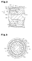
- Fig. 2 is an enlarged cross-sectional view showing the bearing structure of the refrigerant compressor in Fig. 1;
- Fig. 3 is a front cross-sectional view of the bearing structure in Fig. 2;
- Fig. 4 is a front cross-sectional view showing a bearing structure in accordance with a modified embodiment;
- Fig. 5A is a cross-sectional view showing a bearing structure of a refrigerant compressor in accordance with a background art; and
- Fig. 5B is an enlarged cross-sectional view of the bearing structure in Fig. 5A.
- A description will be given below of a bearing structure T in a rotating machine according to one embodiment of the present invention with reference to Figs. 1 to 3. The bearing structure T is employed in a
refrigerant compressor 10 of a vehicle air conditioner. In the following description, a "front" direction and a "rear" direction are defined with reference to a direction of arrow Y shown in Fig. 1. - As shown in Fig. 1, a compressor housing of the
refrigerant compressor 10 is provided with acylinder block 11, afront housing member 12 secured to a front end of thecylinder block 11, and arear housing member 13 secured to a rear end of thecylinder block 11 with a valve/port forming member 14. - A control pressure chamber C is defined in a region surrounded by the
cylinder block 11 and thefront housing member 12. Arotary shaft 18 extends within a control pressure chamber C, and is rotatably supported by thecylinder block 11 and thefront housing member 12. Thefront housing member 12 is provided with a protrudingcylindrical portion 12a so as to extend toward a front side, and a front end portion (a distal end portion) of therotary shaft 18 passes through the protrudingcylindrical portion 12a. Therotary shaft 18 is operationally coupled to a vehicle engine E serving as an external driving source via an electromagnetic clutch mechanism V, and is rotated by a power supplied from the engine E. - The front end portion of the
rotary shaft 18 is rotatably supported by the protrudingcylindrical portion 12a with the bearing structure T provided within the protrudingcylindrical portion 12a. In therotary shaft 18, a portion rearward of the front end portion is inserted to ashaft hole 12b formed in thefront housing member 12, and is rotatably supported by thefront housing member 12 with a first radial bearing 19 (a needle roller bearing) provided within theshaft hole 12b. Further, a rear end portion of therotary shaft 18 is inserted to a shaft hole 11b formed in thecylinder block 11, and is rotatably supported by thecylinder block 11 with a second radial bearing 20 (a needle roller bearing) provided in the shaft hole 11b. In other words, therotary shaft 18 is rotatably supported by the compressor housing at three positions in the axial direction thereof. - In the
front housing member 12, a shaft sealing chamber S is formed between the bearing structure T and the first radial bearing 19 along a center axis L of therotary shaft 18. Within the shaft sealing chamber S, there is provided alip seal 30 serving as a seal member sealing between an outer circumferential surface of therotary shaft 18, and an inner circumferential surface (an inner circumferential surface of theshaft hole 12b) of the shaft sealing chamber S opposing to the outer circumferential surface of therotary shaft 18. Thelip seal 30 is made of a rubber material, comes into close contact with the outer circumferential surface of therotary shaft 18 and the inner circumferential surface of the shaft sealing chamber S, and inhibits a refrigerant gas from leaking out of the compressor housing along the outer circumferential surface of therotary shaft 18. In other words, the lip seal 30 seals an internal space of the compressor housing. - Within the control pressure chamber C, a
rotary support 21 is fixed to therotary shaft 18, and therotary support 21 is integrally rotatable with therotary shaft 18. Aswash plate 22 is accommodated in the control pressure chamber C. Aninsertion hole 22a is formed in a center of theswash plate 22, and therotary shaft 18 is inserted to theinsertion hole 22a. Ahinge mechanism 23 is provided between therotary support 21 and theswash plate 22 to couple these components to each other. Thehinge mechanism 23 rotates theswash plate 22 in synchronization with therotary shaft 18 and therotary support 21, and allows theswash plate 22 to tilt with respect to therotary shaft 18 and to move in a direction along the central axis L of therotary shaft 18. - A plurality of (only one is illustrated in Fig. 1)
cylinder bores 11a are formed around therotary shaft 18 at equal angular intervals, in thecylinder block 11. Each of the cylinder bores 11a extends in a longitudinal direction, that is, in parallel to the central axis L of therotary shaft 18. A single-headedpiston 24 is accommodated in the cylinder bore 11a so as to reciprocate. Front and rear openings of thecylinder bore 11a are closed by the valve/port forming member 14 and thepistons 24, whereby acompression chamber 26 is formed within eachcylinder bore 11a. The volume of eachcompression chamber 26 is changed in correspondence to movement between the top dead center and the bottom dead center of thecorresponding piston 24. Each of thepistons 24 is engaged with an outer peripheral portion of theswash plate 22 with a pair ofshoes 25. - A
suction chamber 13a and adischarge chamber 13b are defined in therear housing member 13 in such a manner as to face the valve/port forming member 14.Suction ports 14a and intake valve flaps 15a are formed in the valve/port forming member 14 in such a manner as to correspond to thesuction chamber 13a and each of the cylinder bores 11a.Discharge ports 14b and dischargevalves 15b are formed in the valve/port forming member 14 in such a manner as to correspond to thedischarge chamber 13b and each of the cylinder bores 11a. Further, an electromagnetic displacement control valve CV is installed in therear housing member 13. - In accordance with the movement of each
piston 24 from the top dead center toward the bottom dead center accompanying the rotation of therotary shaft 18, the refrigerant gas within thesuction chamber 13a passes through the correspondingsuction port 14a and is drawn into the correspondingcompression chamber 26. The refrigerant gas within thecompression chamber 26 is compressed by the movement of thepiston 24 from the bottom dead center toward the top dead center, and passes through thecorresponding discharge port 14b so as to be discharged to thedischarge chamber 13b. The refrigerant gas discharged to thedischarge chamber 13b is led out to an externalrefrigerant circuit 28. The refrigerant gas led out to the externalrefrigerant circuit 28 is supplied to an evaporator 28c via a condenser 28a and anexpansion valve 28b. The refrigerant gas supplied to the evaporator 28c and heat-exchanged is returned to thesuction chamber 13a. Therefrigerant compressor 10 constructs a refrigerant circuit together with the externalrefrigerant circuit 28. Further, a compression mechanism in therefrigerant compressor 10 is structured by thecylinder block 11 having the cylinder bores 11a, therotary shaft 18, therotary support 21, theswash plate 22, thehinge mechanism 23, thepistons 24, and theshoes 25. The compression mechanism is driven on the basis of the rotation of therotary shaft 18. - The
refrigerant compressor 10 is provided with asupply passage 29 connecting thedischarge chamber 13b and the control pressure chamber C to each other. Thesupply passage 29 supplies the refrigerant gas in thedischarge chamber 13b as a control gas to the control pressure chamber C. The displacement control valve CV is provided on thesupply passage 29. Therefrigerant compressor 10 is provided with arelease passage 17 connecting the control pressure chamber C and thesuction chamber 13a to each other. Therelease passage 17 discharges the refrigerant gas in the control pressure chamber C to thesuction chamber 13a. The displacement control valve CV regulates the amount of the refrigerant gas supplied to the control pressure chamber C from thedischarge chamber 13b through thesupply passage 29. - The pressure in the control pressure chamber C is determined on the basis of the amount of the refrigerant gas supplied to the control pressure chamber C from the
discharge chamber 13b through thesupply passage 29, and the amount of the refrigerant gas released to thesuction chamber 13a from the control pressure chamber C through therelease passage 17. If the pressure in the control pressure chamber C is changed, a differential pressure between the inside of the control pressure chamber C and the inside of the cylinder bore 11a via thepiston 24 is changed, and the inclination angle theswash plate 22 is changed. As a result, the stroke of thepistons 24 is changed, and the displacement of therefrigerant compressor 10 is adjusted. In other words, therefrigerant compressor 10 in accordance with the present embodiment is a variable displacement compressor. - Next, a description will be given in detail of the electromagnetic clutch mechanism V. As shown in Fig. 1, a
rotor 41 serving as a second rotor is rotatably supported by the outer circumferential surface of the protrudingcylindrical portion 12a with aradial bearing 40. Therotor 41 is made of a magnetic material and is formed in a cylindrical shape. Therotor 41, that is, a pulley has an integrally formed belt receiving portion 41a. An endless belt (not shown) is wound around an output shaft of the vehicle engine E and the belt receiving portion 41a. - An
electromagnetic coil 42 formed of a magnetic material is accommodated in therotor 41, and an electric current is supplied to theelectromagnetic coil 42 in such a manner as to switch the flowing direction between forward and reverse directions. Acylindrical body 46 constructing a part of therotary shaft 18 is screwed to a front end portion of therotary shaft 18. A distal end portion (a front end portion) of thecylindrical body 46 protrudes to the outside of the protrudingcylindrical portion 12a, and ahub 45 is fixed to the distal end portion of thecylindrical body 46. Thehub 45 is integrally rotatable with therotary shaft 18 and thecylindrical body 46. Thehub 45 is formed as a disc extending in a direction orthogonal to the central axis L of therotary shaft 18. Thecylindrical body 46 integrally forms with thehub 45, and thecylindrical body 46 and thehub 45 structure a first rotor. - An
armature 48 is fixed to a radially outer portion of thehub 45 in such a manner as to oppose to therotor 41. Thearmature 48 is formed of a magnetic material. Thearmature 48 has afirst friction surface 48f opposing to therotor 41, and therotor 41 has a second friction surface 41f opposing to thefirst friction surface 48f. A uniform air gap G is defined between thefirst friction surface 48f and the second friction surface 41f. - If the
electromagnetic coil 42 is excited by applying current to theelectromagnetic coil 42 in the forward direction, an attraction force on the basis of an electromagnetic force is applied to thearmature 48. Accordingly, thearmature 48 moves toward therotor 41. On the other hand, if theelectromagnetic coil 42 is excited by applying current to theelectromagnetic coil 42 in the reverse direction, a magnetic flux is generated in theelectromagnetic coil 42 in a reverse direction to the case of applying current in the forward direction. Accordingly, thearmature 48 moves away from therotor 41. - If the
armature 48 moves toward therotor 41 on the basis of the current application in the forward direction to theelectromagnetic coil 42, the air gap G disappears. In other words, thefirst friction surface 48f is caused to contact the second friction surface 41f. Therefore, therotor 41 and thearmature 48 are coupled in accordance with friction engagement, and therotor 41 and thehub 45 are coupled so as to be integrally rotatable. Accordingly, it is possible to transmit the power from the engine E to therotary shaft 18. - On the other hand, if the
armature 48 moves away from therotor 41 on the basis of the current application in the reverse direction to theelectromagnetic coil 42, the friction engagement between the friction surfaces 48f and 41f is canceled. In other words, the electromagnetic clutch mechanism V comes to a non-coupled state, the coupling between therotor 41 and thearmature 48, that is, the coupling between therotor 41 and thehub 45 is canceled, and the power transmission from the engine E to therotary shaft 18 is shut off. - Next, a description will be given of the bearing structure T.
- As shown in Figs. 2 and 3, a
damper member 53 is fitted to an outercircumferential surface 46a of thecylindrical body 46 in such a manner as to oppose to the innercircumferential surface 12c of the protrudingcylindrical portion 12a. Thedamper member 53 is integrally formed with thecylindrical body 46, that is, therotary shaft 18. Thedamper member 53 is formed in a cylindrical shape, and is formed by an acrylic resin, which is a synthetic resin. Thedamper member 53 is elastically deformable at least in a radial direction. Thedamper member 53 has a high impact resistance by being formed by the acrylic resin. Thedamper member 53 is integrally rotated with therotary shaft 18. - A
radial bearing 50 is provided between the innercircumferential surface 12c of the protrudingcylindrical portion 12a and the outercircumferential surface 53a of thedamper member 53. The front end portion, that is, thecylindrical body 46 of therotary shaft 18 is rotatably supported by the protrudingcylindrical portion 12a with theradial bearing 50. Theradial bearing 50 is a ball bearing in which balls B (rolling elements) are interposed between anouter ring 51 and aninner ring 52. Theouter ring 51 is press-fitted to the innercircumferential surface 12c of the protrudingcylindrical portion 12a, whereby theradial bearing 50 is fixed to the protrudingcylindrical portion 12a. - The
damper member 53 is provided in an annular clearance F formed between an innercircumferential surface 52a of theinner ring 52 of theradial bearing 50 and the outercircumferential surface 46a of thecylindrical body 46 over the entire circumference of the clearance F. In other words, the entire outercircumferential surface 53a of thedamper member 53 is pressed against the entire innercircumferential surface 52a of theinner ring 52, and the entire innercircumferential surface 53b of thedamper member 53 is pressed against the outercircumferential surface 46a of thecylindrical body 46. In a state of detaching thedamper member 53, the thickness of thedamper member 53 in a radial direction is larger than the size of the clearance F in the radial direction. In other words, thedamper member 53 is arranged in a state of being compressed and deformed between the innercircumferential surface 52a and the outercircumferential surface 46a. Therotary shaft 18 is supported by the bearing structure T at a portion frontward of a portion supported by the firstradial bearing 19. - As mentioned above, the
rotary shaft 18 is supported by the firstradial bearing 19 and the secondradial bearing 20, and a portion of therotary shaft 18 that is forward of the firstradial bearing 19, that is, thecylindrical body 46 is supported by the bearing structure T including theradial bearing 50. A portion of therotary shaft 18 that is forward of theradial bearing 50 is in a state of being supported in a cantilever manner, however, a length of the position under the cantilever supported state is a little. - The bearing structure T is assembled as follows. First, the
damper member 53 is fitted to the outercircumferential surface 46a of thecylindrical body 46 screwed to therotary shaft 18. Next, theradial bearing 50 is press-fitted to the portion between the outercircumferential surface 53a of thedamper member 53 and the innercircumferential surface 12c of the protrudingcylindrical portion 12a. Accordingly, thedamper member 53 is elastically deformed in the radial direction, and the press fitting of theradial bearing 50 is allowed. When the press fitting of theradial bearing 50 is finished, the entire outercircumferential surface 53a of thedamper member 53 is pressed against the entire innercircumferential surface 52a of theinner ring 52 of theradial bearing 50, and the entire innercircumferential surface 53b of thedamper member 53 is pressed against the outercircumferential surface 46a of thecylindrical body 46. - Next, advantages of the present embodiment will be described below.
- (1) The
rotary shaft 18 is rotatably supported by the firstradial bearing 19 and the secondradial bearing 20 within the compressor housing. Further, a portion of therotary shaft 18 that is forward of the portion supported by the firstradial bearing 19 is rotatably supported by theradial bearing 50. Accordingly, a significantly short portion of therotary shaft 18 that is frontward of a portion supported by theradial bearing 50 is supported in a cantilever manner. As a result, the front end portion of therotary shaft 18 is hard to be flexed. - Further, the outer
circumferential surface 53a of thedamper member 53 is pressed against the innercircumferential surface 52a of theinner ring 52 of theradial bearing 50, and the innercircumferential surface 53b of thedamper member 53 is pressed against the outercircumferential surface 46a of the cylindrical body 46 (the first rotor). Accordingly, if the force vibrating therotary shaft 18 in the radial direction is applied, the vibration of therotary shaft 18 is suppressed by elastic deformation of thedamper member 53, and the vibration of thehub 45 in accordance with the vibration of therotary shaft 18 is suppressed. As a result, the collision of thehub 45 with respect to therotor 41 is suppressed, and it is possible to suppress noise caused by such collision. - (2) In the front end portion of the
rotary shaft 18, thedamper member 53 is arranged between the innercircumferential surface 52a of theinner ring 52 of theradial bearing 50 and the outercircumferential surface 46a of thecylindrical body 46. Accordingly, the clearance F between the innercircumferential surface 52a of theinner ring 52 of theradial bearing 50 and the outercircumferential surface 46a of thecylindrical body 46 is filled with thedamper member 53. Accordingly, it is possible to prevent therotary shaft 18 from being moved in the radial direction so that thecylindrical body 46 comes into collision with theradial bearing 50. As a result, it is possible to prevent theradial bearing 50 from being damaged by the collision between thecylindrical body 46 and theinner ring 52, and prevent the noise from being generated. - (3) A portion of the
rotary shaft 18 that is frontward of the portion supported by the firstradial bearing 19 is supported by theradial bearing 50. Thedamper member 53 is provided between the innercircumferential surface 52a of theradial bearing 50 and the outercircumferential surface 46a of thecylindrical body 46. Accordingly, it is possible to inhibit the front end portion of therotary shaft 18 from being vibrated, and it is possible to inhibit thelip seal 30 from being largely elastically deformed by the vibration of therotary shaft 18. As a result, it is possible to suppress deterioration and a damage caused by the elastic deformation of thelip seal 30, and it is possible to achieve an improved sealing performance in thelip seal 30 over a long period of time. - (4) The
damper member 53 is formed of an acrylic resin and has a high impact resistance. Accordingly, even if thecylindrical body 46 comes into contact with thedamper member 53, thedamper member 53 is hardly damaged or broken, and it is possible to reliably support therotary shaft 18. Further, since thedamper member 53 is elastically deformable, it is possible to easily execute a fitting work of thedamper member 53 to thecylindrical body 46 and an installing work of theradial bearing 50 to the outer circumference of thedamper member 53, for example, in comparison with the case that thedamper member 53 is formed by a metal material. Therefore, it is possible to easily execute the assembling work of the bearing structure T. - (5) The
damper member 53 serves as a member absorbing manufacturing tolerance and assembling tolerance. Since the tolerances are absorbed by thedamper member 53, therotary shaft 18 is supported in a stable state by three bearings arranged along the axial direction, comprising theradial bearing 50, the firstradial bearing 19, and the secondradial bearing 20. - (6) The
damper member 53 is fitted to thecylindrical body 46, and is arranged between the outercircumferential surface 46a of thecylindrical body 46 and the innercircumferential surface 52a of theradial bearing 50. Accordingly, thedamper member 53 directly bears and absorbs the vibration of therotary shaft 18, and effectively suppresses the vibration of therotary shaft 18. - (7) The
hub 45 is integrally formed in thecylindrical body 46. Since thedamper member 53 is provided between the outercircumferential surface 46a of thecylindrical body 46 and the innercircumferential surface 52a of theradial bearing 50, no gap exists between theradial bearing 50 and thecylindrical body 46. Accordingly, the vibration of therotary shaft 18, that is, the vibration of thehub 45 is directly suppressed by thedamper member 53. - (8) The
damper member 53 is formed in the cylindrical shape, and thedamper member 53 is provided over the entire circumference of the annular clearance F between the innercircumferential surface 52a of theradial bearing 50 and the outercircumferential surface 46a of thecylindrical body 46. Accordingly, the entire innercircumferential surface 53b of thedamper member 53 is pressed against the entire outercircumferential surface 46a of thecylindrical body 46, and it is possible to suppress the vibration in all the directions of the circumferential direction of therotary shaft 18. - (9) The
radial bearing 50 is constituted by the ball bearing comprising theouter ring 51, theinner ring 52, and the balls B. The force for vibrating therotary shaft 18 is applied to theradial bearing 50 via thedamper member 53, but, is also absorbed by the rolling of the balls B in theradial bearing 50. Accordingly, it is possible to support therotary shaft 18 by a smaller friction, for example, in comparison with the case that a slide bearing is used as theradial bearing 50. - The above described embodiment may be modified as follows.
- As shown in Fig. 4, the structure may be made such that the
damper member 53 is provided between the outercircumferential surface 51a of theouter ring 51 of theradial bearing 50 and the innercircumferential surface 12c of the protrudingcylindrical portion 12a opposing to the outercircumferential surface 51a, and thedamper member 53 is pressed against thecircumferential surfaces - The
damper member 53 may be divided, for example, into a plurality of narrow plates, in place of being formed in the cylindrical shape, and a plurality ofdamper members 53 may be arranged along the circumferential direction between the innercircumferential surface 52a of theradial bearing 50 and the outercircumferential surface 46a of thecylindrical body 46. - The
damper member 53 may be formed of a soft metal such as lead, tin, or copper, or a rubber material, or, polyamideimide resin, in stead of the acrylic resin. - The
hub 45 may be directly fixed to therotary shaft 18 by deleting thecylindrical body 46. In this case, thedamper member 53 is provided between the circumferential surface of therotary shaft 18 and the innercircumferential surface 52a of theradial bearing 50. - The
refrigerant compressor 10 may be constituted by a double-headed piston type compressor, in which double-headed pistons execute compressing motion in the cylinder bores 11a provided in both front and rear sides with respect to the control pressure chamber C, in place of the single-headed piston type compressor, in which the single-headedpistons 24 execute compressing motion. - In place of the structure in which the
swash plate 22 is integrally rotated with therotary shaft 18, therefrigerant compressor 10 may be a compressor of a type that theswash plate 22 is rotatably supported with respect to therotary shaft 18. For example, thecompressor 10 may be of a wobble type. - The
refrigerant compressor 10 may be structured as a fixed displacement type in which the stroke of thepistons 24 cannot be changed. - The rotating machine is embodied by the piston
type refrigerant compressor 10 in which thepistons 24 execute the reciprocating motion. However, the present invention may be applied to any types of rotating machines as long as the power is transmitted from the external driving source via the electromagnetic clutch mechanism V. - As the second rotor, a sprocket, a gear or the like may be applied, in addition to the rotor 41 (the pulley).
- The compressor may employ a clutchless system in which the
rotor 41 and thehub 45 are integrated so that power is always transmitted to therotary shaft 18 from the engine E.
Claims (13)
- A bearing structure for a rotating machine (10), the rotating machine (10) including:a housing having a protruding cylindrical portion (12a);a rotary shaft (18) rotatably supported by the housing and having a distal end portion inserted to the protruding cylindrical portion (12a);a first rotor fixed to a distal end portion of the rotary shaft (18); anda second rotor (41) that is coaxial with the first rotor and rotatably supported by an outer circumference of the protruding cylindrical portion (12a) in such a manner as to oppose to the first rotor, whereby power from an external driving source is transmittable to the rotary shaft (18) via the second rotor (41) and the first rotor,the bearing structure comprising:a radial bearing (50) provided in the protruding cylindrical portion (12a) and supporting a distal end portion of the rotary shaft (18); anda damper member (53) provided in a clearance formed either between an inner circumferential surface of the radial bearing and an outer circumferential surface of the first rotor, the outer circumferential surface opposing the inner circumferential surface in a radial direction, or between an outer circumferential surface of the radial bearing and an inner circumferential surface of the protruding cylindrical portion (12a), the inner circumferential surface opposing the outer circumferential surface in the radial direction, the damper member (53) being pressed against the inner circumferential surface and the outer circumferential surface, the inner and the outer circumferential surfaces opposing each other with the damper member (53) in between.
- The bearing structure according to claim 1, characterized in that the damper member (53) is made of an acrylic resin.
- The bearing structure according to claim 1 or 2, characterized in that the clearance is formed in an annular shape.
- The bearing structure according to any of claims 1 to 3, characterized in that the damper member (53) is formed in a cylindrical shape in such a manner as to be provided over the entire circumference of the clearance.
- The bearing structure according to any one of claims 1 to 4, characterized in that the rotating machine (10) is a refrigerant compressor provided with a comopression mechanism that is provided within the housing and compresses refrigerant gas in accordance with rotation of the rotary shaft (18).
- The bearing structure according to claim 5, wherein a seal member (30) is provided between the compression mechanism and the radial bearing (50) in an axial direction of the rotary shaft (18), the seal member (30) suppressing leakage of the refrigerant gas.
- The bearing structure according to claim 6, wherein the seal member (30) is arranged to suppress leakage from a portion between an outer circumferential surface of the rotary shaft (18) and an inner circumferential surface of the housing opposing to the outer circumferential surface of the rotary shaft (18) to the outside of the housing.
- The bearing structure according to any one of claims 1 to 7, characterized in that the first rotor and the second rotor (41) are formed as independent bodies.
- The bearing structure according to claim 8, wherein the first rotor and the second rotor (41) construct an electromagnetic clutch mechanism.
- The bearing structure according to any one of claims 1 to 7, characterized in that the first rotor and the second rotor (41) are integrally formed.
- The bearing structure according to claim 10, wherein the first rotor and the second rotor (41) are arranged so that power from the external driving source (E) is always transmitted to the rotary shaft (18).
- The bearing structure according to any one of claims 1 to 11, characterized in that the radial bearing (40) is a ball bearing.
- The bearing structure according to any one of claims 1 to 12, characterized in that the damper member (53) is arranged in a state of being compressed and deformed between the inner circumferential surface and the outer circumferential surface.
Applications Claiming Priority (1)
| Application Number | Priority Date | Filing Date | Title |
|---|---|---|---|
| JP2006296128A JP2008111519A (en) | 2006-10-31 | 2006-10-31 | Bearing structure for rotary machine |
Publications (2)
| Publication Number | Publication Date |
|---|---|
| EP1918582A2 true EP1918582A2 (en) | 2008-05-07 |
| EP1918582A3 EP1918582A3 (en) | 2011-10-05 |
Family
ID=38669961
Family Applications (1)
| Application Number | Title | Priority Date | Filing Date |
|---|---|---|---|
| EP07021251A Withdrawn EP1918582A3 (en) | 2006-10-31 | 2007-10-31 | Bearing structure in rotating machine |
Country Status (2)
| Country | Link |
|---|---|
| EP (1) | EP1918582A3 (en) |
| JP (1) | JP2008111519A (en) |
Cited By (2)
| Publication number | Priority date | Publication date | Assignee | Title |
|---|---|---|---|---|
| CN103237702A (en) * | 2010-11-30 | 2013-08-07 | 大陆-特韦斯贸易合伙股份公司及两合公司 | Motor-pump assembly |
| DE102017004087A1 (en) * | 2017-04-28 | 2018-10-31 | Wabco Gmbh | Compressor arrangement for a compressed air supply of a compressed air supply system |
Family Cites Families (9)
| Publication number | Priority date | Publication date | Assignee | Title |
|---|---|---|---|---|
| JPH05149247A (en) * | 1991-11-29 | 1993-06-15 | Sanden Corp | Compressor |
| US5380161A (en) * | 1992-12-11 | 1995-01-10 | Kabushiki Kaisha Toyoda Jidoshokki Seisakusho | Variable capacity swash-plate compressor with electromagnetic clutch |
| JP2001208055A (en) * | 2000-01-27 | 2001-08-03 | Koyo Seiko Co Ltd | Rolling bearing device |
| JP3691717B2 (en) * | 2000-03-22 | 2005-09-07 | ジヤトコ株式会社 | Hybrid vehicle transmission unit |
| JP2002098213A (en) * | 2000-09-22 | 2002-04-05 | Toyota Industries Corp | Power transmission mechanism |
| JP2003056461A (en) * | 2001-02-15 | 2003-02-26 | Denso Corp | Combined drive system for compressor |
| JP2003083395A (en) * | 2001-06-28 | 2003-03-19 | Toyota Industries Corp | Rotary machine |
| JP2006057490A (en) * | 2004-08-18 | 2006-03-02 | Calsonic Kansei Corp | Compressor |
| JP2006170420A (en) * | 2004-12-20 | 2006-06-29 | Jtekt Corp | Outer ring for split bearing and split bearing with the same |
-
2006
- 2006-10-31 JP JP2006296128A patent/JP2008111519A/en active Pending
-
2007
- 2007-10-31 EP EP07021251A patent/EP1918582A3/en not_active Withdrawn
Cited By (4)
| Publication number | Priority date | Publication date | Assignee | Title |
|---|---|---|---|---|
| CN103237702A (en) * | 2010-11-30 | 2013-08-07 | 大陆-特韦斯贸易合伙股份公司及两合公司 | Motor-pump assembly |
| CN103237702B (en) * | 2010-11-30 | 2016-11-16 | 大陆-特韦斯贸易合伙股份公司及两合公司 | Motor pump assembly |
| DE102017004087A1 (en) * | 2017-04-28 | 2018-10-31 | Wabco Gmbh | Compressor arrangement for a compressed air supply of a compressed air supply system |
| US10851894B2 (en) | 2017-04-28 | 2020-12-01 | Wabco Gmbh | Compressor assembly for a compressed-air feed of a compressed-air supply system |
Also Published As
| Publication number | Publication date |
|---|---|
| EP1918582A3 (en) | 2011-10-05 |
| JP2008111519A (en) | 2008-05-15 |
Similar Documents
| Publication | Publication Date | Title |
|---|---|---|
| US8371426B2 (en) | Power transmission mechanism | |
| EP1207316A1 (en) | Power transmission mechanism | |
| US20090107327A1 (en) | Capacity-variable type swash plate compressor | |
| KR100389013B1 (en) | Piston-type compressor and method for assembling the same | |
| US20080031749A1 (en) | Power transmission mechanism | |
| EP1197672A1 (en) | Power transmission mechanism | |
| JPH11159453A (en) | Torsional resonance dampting structure of driving system in compressor | |
| US10851842B2 (en) | Power transmission device | |
| EP2096307A2 (en) | Tilting plate type compressor | |
| US5737997A (en) | Cam plate supporting structure in a cam plate type compressor | |
| KR20120134859A (en) | compressor | |
| KR101599547B1 (en) | Swash plate compressor | |
| JP2008111519A (en) | Bearing structure for rotary machine | |
| KR200351633Y1 (en) | Compressor | |
| KR101644316B1 (en) | Swash plate type compressor | |
| KR100964532B1 (en) | Swash pate type compressor | |
| KR101452501B1 (en) | compressor | |
| KR100326163B1 (en) | Airconditioner compressor of vehicle | |
| KR101107337B1 (en) | Swash plate compressor | |
| KR101166286B1 (en) | Swash plate type compressor | |
| KR101409017B1 (en) | Compressor | |
| KR101463259B1 (en) | Compressor | |
| JP2008111408A (en) | Bearing structure in rotary machine | |
| JP2005188328A (en) | Piston type compressor | |
| KR101515643B1 (en) | Compressor |
Legal Events
| Date | Code | Title | Description |
|---|---|---|---|
| PUAI | Public reference made under article 153(3) epc to a published international application that has entered the european phase |
Free format text: ORIGINAL CODE: 0009012 |
|
| 17P | Request for examination filed |
Effective date: 20071031 |
|
| AK | Designated contracting states |
Kind code of ref document: A2 Designated state(s): AT BE BG CH CY CZ DE DK EE ES FI FR GB GR HU IE IS IT LI LT LU LV MC MT NL PL PT RO SE SI SK TR |
|
| AX | Request for extension of the european patent |
Extension state: AL BA HR MK RS |
|
| PUAL | Search report despatched |
Free format text: ORIGINAL CODE: 0009013 |
|
| AK | Designated contracting states |
Kind code of ref document: A3 Designated state(s): AT BE BG CH CY CZ DE DK EE ES FI FR GB GR HU IE IS IT LI LT LU LV MC MT NL PL PT RO SE SI SK TR |
|
| AX | Request for extension of the european patent |
Extension state: AL BA HR MK RS |
|
| RIC1 | Information provided on ipc code assigned before grant |
Ipc: F16C 27/00 20060101ALI20110831BHEP Ipc: F04B 39/00 20060101ALI20110831BHEP Ipc: F04B 27/08 20060101ALI20110831BHEP Ipc: F04B 1/20 20060101ALI20110831BHEP Ipc: F04B 1/14 20060101ALI20110831BHEP Ipc: F04B 27/10 20060101AFI20110831BHEP |
|
| 17Q | First examination report despatched |
Effective date: 20110920 |
|
| AKX | Designation fees paid |
Designated state(s): AT BE BG CH CY CZ DE DK EE ES FI FR GB GR HU IE IS IT LI LT LU LV MC MT NL PL PT RO SE SI SK TR |
|
| STAA | Information on the status of an ep patent application or granted ep patent |
Free format text: STATUS: THE APPLICATION IS DEEMED TO BE WITHDRAWN |
|
| 18D | Application deemed to be withdrawn |
Effective date: 20120131 |