EP1918463A2 - Engine load management for power machines - Google Patents
Engine load management for power machines Download PDFInfo
- Publication number
- EP1918463A2 EP1918463A2 EP07118513A EP07118513A EP1918463A2 EP 1918463 A2 EP1918463 A2 EP 1918463A2 EP 07118513 A EP07118513 A EP 07118513A EP 07118513 A EP07118513 A EP 07118513A EP 1918463 A2 EP1918463 A2 EP 1918463A2
- Authority
- EP
- European Patent Office
- Prior art keywords
- drive
- speed
- signal
- engine
- actuation
- Prior art date
- Legal status (The legal status is an assumption and is not a legal conclusion. Google has not performed a legal analysis and makes no representation as to the accuracy of the status listed.)
- Withdrawn
Links
Images



Classifications
-
- E—FIXED CONSTRUCTIONS
- E02—HYDRAULIC ENGINEERING; FOUNDATIONS; SOIL SHIFTING
- E02F—DREDGING; SOIL-SHIFTING
- E02F9/00—Component parts of dredgers or soil-shifting machines, not restricted to one of the kinds covered by groups E02F3/00 - E02F7/00
- E02F9/20—Drives; Control devices
- E02F9/22—Hydraulic or pneumatic drives
- E02F9/2253—Controlling the travelling speed of vehicles, e.g. adjusting travelling speed according to implement loads, control of hydrostatic transmission
-
- B—PERFORMING OPERATIONS; TRANSPORTING
- B62—LAND VEHICLES FOR TRAVELLING OTHERWISE THAN ON RAILS
- B62D—MOTOR VEHICLES; TRAILERS
- B62D11/00—Steering non-deflectable wheels; Steering endless tracks or the like
- B62D11/001—Steering non-deflectable wheels; Steering endless tracks or the like control systems
- B62D11/003—Electric or electronic control systems
-
- B—PERFORMING OPERATIONS; TRANSPORTING
- B62—LAND VEHICLES FOR TRAVELLING OTHERWISE THAN ON RAILS
- B62D—MOTOR VEHICLES; TRAILERS
- B62D11/00—Steering non-deflectable wheels; Steering endless tracks or the like
- B62D11/02—Steering non-deflectable wheels; Steering endless tracks or the like by differentially driving ground-engaging elements on opposite vehicle sides
- B62D11/06—Steering non-deflectable wheels; Steering endless tracks or the like by differentially driving ground-engaging elements on opposite vehicle sides by means of a single main power source
-
- E—FIXED CONSTRUCTIONS
- E02—HYDRAULIC ENGINEERING; FOUNDATIONS; SOIL SHIFTING
- E02F—DREDGING; SOIL-SHIFTING
- E02F9/00—Component parts of dredgers or soil-shifting machines, not restricted to one of the kinds covered by groups E02F3/00 - E02F7/00
- E02F9/20—Drives; Control devices
- E02F9/22—Hydraulic or pneumatic drives
- E02F9/225—Control of steering, e.g. for hydraulic motors driving the vehicle tracks
-
- E—FIXED CONSTRUCTIONS
- E02—HYDRAULIC ENGINEERING; FOUNDATIONS; SOIL SHIFTING
- E02F—DREDGING; SOIL-SHIFTING
- E02F9/00—Component parts of dredgers or soil-shifting machines, not restricted to one of the kinds covered by groups E02F3/00 - E02F7/00
- E02F9/20—Drives; Control devices
- E02F9/22—Hydraulic or pneumatic drives
- E02F9/2278—Hydraulic circuits
- E02F9/2292—Systems with two or more pumps
-
- E—FIXED CONSTRUCTIONS
- E02—HYDRAULIC ENGINEERING; FOUNDATIONS; SOIL SHIFTING
- E02F—DREDGING; SOIL-SHIFTING
- E02F9/00—Component parts of dredgers or soil-shifting machines, not restricted to one of the kinds covered by groups E02F3/00 - E02F7/00
- E02F9/20—Drives; Control devices
- E02F9/22—Hydraulic or pneumatic drives
- E02F9/2278—Hydraulic circuits
- E02F9/2296—Systems with a variable displacement pump
Definitions
- the present discussion is related to power machines. More particularly, the present discussion is related to providing a propelling force to cause power machines to move.
- Power machines such as skid steer loaders, tracked vehicles, mini-excavators, utility vehicles, wheel loaders and the like have high utility in construction, landscaping, agriculture, and many other types of applications.
- Power machines of this type have a power source such as an engine that supplies a power that can cause the power machine to be propelled under the control of an operator.
- many power machines of this type utilize tools such as buckets to engage in activities such as earth moving. Digging often involves engaging materials that provide significant resistance, which in turn applies a load onto the power source of the power machine. The applied load can result in reduced performance of the power machine because of loss of power from the power source.
- a method of controlling a drive system for a power machine having an engine includes the steps of receiving a control signal and calculating a base output value based on the control signal. The method further includes compensating the base output value for a load applied to the engine. A signal indicative of the compensated output value is then provided to a drive component.
- a power machine having an engine and a drive system including an axle with a rotatable member.
- the drive system is coupled to the engine.
- the power machine includes an operator control device that is configured to provide an input signal.
- the input signal is indicative of a desired rotational speed of the rotational member of the axle.
- the power machine also includes an engine speed sensor configured to provide an engine speed signal indicative of the speed of the engine.
- a drive system component is operably coupled to the axle.
- the drive system component has an actuation device capable of receiving an actuation signal to cause the actuation device to be actuated.
- the power machine also includes a controller.
- the controller is configured to receive the input signal and the engine speed signal.
- the controller provides the actuation signal to cause the drive system component to supply power to move the rotatable member of the axle based at least in part upon the engine speed signal.
- a drive system for a power machine that has an engine.
- the drive system includes a controller configured to receive an engine speed signal indicative of the speed of the engine and first and second rotatable axles.
- the drive system also includes first and second drive control mechanisms that are operably coupled to the engine.
- the first drive control mechanism has a first actuation device configured to receive a first actuation signal.
- the second drive control mechanism has a second actuation device configured to receive a second actuation signal.
- the controller provides first and second actuation signals to the first and second actuation devices, each of which are functions of the engine speed signal.
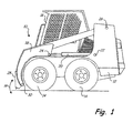
- FIG. 1 illustrates a power machine 10 of the type in which an engine load management system can be usefully employed.
- Power machine 10 includes a frame 12 that is supported by wheels 14.
- Power machine 10 has an engine (not shown in FIG. 1) that applies power to a drive system (not shown in FIG. 1), which in turn supplies power to the wheels 14 causing power machine 10 to move under the control of an operator. Examples of suitable drive systems for power machine 10 will be discussed in more detail below.
- Frame 12 supports a cab 16, which defines an operating compartment.
- An operator can be located inside the cab 16 and control the power machine 10 by manipulating control devices (not shown in FIG. 1) located therein to send operator input signals to the drive system.
- control devices not shown in FIG. 1
- power machine 10 is shown having a plurality of wheels 14, it should be appreciated that power machine 10 need not have wheels.
- power machine 10 can be equipped with one or more tracks that are configured to engage a supporting surface, such as ground, to propel the power machine over the supporting surface.
- Power machine 10, as illustrated in FIG. 1, further includes a lift arm 18.
- Lift arm 18 is coupled to frame 12 at pivot point 26.
- Actuator 20 is coupled to the frame 12 at first pivot point 22 and the lift arm at second pivot point 24.
- Actuator 20, of the power machine 10 shown in FIG. 1 is a hydraulic cylinder, although other suitable types of actuators may be used.
- a single lift arm 18 is shown in FIG. 1, but it is to be understood that a similar lift arm 18 and corresponding actuator 20 may be positioned on the opposite side of the cab and similarly attached to frame 12. Further, it should be understood that such a lift arm may be coupled to the lift arm 18 shown in FIG. 1 via a cross-member (not shown) extending between and attached to each of the lift arms 18.
- Power machine 10 further includes an attachment interface 28, which is rotatably coupled to the lift arm 18 about attachment point 30.
- One or more tilt actuators are coupled to the attachment interface 28 and the one or more lift arms 18 (or the cross-member therebetween). Actuation of the one or more tilt actuators causes the attachment interface 28 to rotate about the attachment point 30 in a direction shown by arrow 38.
- Attachment interface 28 is configured to engage and be attached to a variety of different work implements such as a bucket, a planer, a post-hole auger, and the like.
- the power machine 10 provides a desirable and suitable tool to accomplish a number of different types of tasks. For example, by attaching a bucket (not shown) to power machine 10, an operator is capable of digging earth, moving material, and any number of tasks related to landscaping, construction, material removal, or any number of different types of applications.
- the power machine 10 illustrated in FIG. 1 is a skid steer loader.
- a skid steer loader has rigid axles coupled to each of the wheels 14.
- the wheels 14 on each side of the skid steer loader are operably coupled to each so that they operate in tandem.
- Each side of the skid steer loader has its own drive system, which supplies power to the wheels on that particular side. Steering is accomplished by controlling the drive system of one or both sides of the machine to cause the machine to skid on the supporting surface in a direction that is desired by the operator.
- an operator wishing to move or turn power machine 10 to the right may cause the wheels 14 on the left side of the power machine 10 to move in a forward direction.
- the operator can cause the wheels 14 on the right side to move in a reverse direction, not at all, or in a forward direction at a lesser rate of speed than the left side wheels 14.
- the net effect is a forward force applied to the left side of the power machine 10 that is greater than the forward force applied to the right hand side.
- the power machine 10 will skid on its wheels 14 to the right.
- the discussion provided in this document need not be limited to skid steer loaders.
- the discussion herein can be applied to other power machines such as wheeled loaders with a front or rear steerable axle, excavators, utility vehicles, all-wheel steer vehicles, tracked loaders, or any other similar power machine.
- FIG. 2 illustrates a block diagram of a drive system 100 for providing a propelling power to cause power machine 10 to move in accordance with one illustrative embodiment.
- Drive system 100 receives power from an engine 102 that is located within the power machine 10.
- Engine 102 is coupled to a drive mechanism 104 to provide the drive mechanism 104 with an input power source.
- Drive mechanism 104 receives drive control signals indicated by block 106 from an operator to control the drive mechanism 104.
- Drive mechanism 104 then provides an output to wheels 108 (or alternatively, for example, tracks) to cause the power machine 10 to move.
- the drive mechanism 104 includes a hydraulic or hydrostatic drive system. Other types of drive mechanisms can be used without departing from the spirit and scope of the discussion.
- Drive control 106 provides drive signals to the drive mechanism 104 in response to manipulation by an operator of one or more control devices such as levers, buttons, dials, pedals, joysticks, or any other type of actuable control device that may be appropriate.
- control devices such as levers, buttons, dials, pedals, joysticks, or any other type of actuable control device that may be appropriate.
- the power machine 10 is illustratively described as a skid steer loader, steering the power machine 10, as well as propelling, is accomplished by the operation of the drive mechanism 104.
- steering control devices that are separate from the drive mechanism in a particular power machine may or may not be relevant to the control of that drive mechanism.
- power machine 10 can utilize various attachments to accomplish a wide variety of tasks in different applications.
- One particular application mentioned above is the use of a bucket for digging.
- the resistance that the power machine 10 can encounter from moving into and engaging tightly compacted earth causes the power to slow down and also transfers a load onto the engine 102.
- An operator can reduce the load on engine 102 by manipulating the control devices to reduce the drive signals provided by drive control 106 to the drive mechanism 104, which in turn causes the drive mechanism to reduce the power supplied to the wheels 108.
- the load on the engine 102 is reduced.
- the operator may have to vary his or her manipulation of control devices to prevent the engine 102 from stopping.
- the drive system 100 can operate the power machine 10 with an efficient load on the engine 102. Therefore, the engine 102 can operate at an optimum speed and supply an optimum torque so that the power machine 10 can accomplish work efficiently.
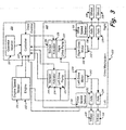
- FIG. 3 illustrates the drive system 100, which is configured to manage a load on its engine, in more detail according to one illustrative embodiment.
- Drive control 106 includes a controller 112 that is configured to receive one or more operator inputs 110.
- Operator inputs 110 include a pair of inputs, one for the left-hand side of the power machine 10 and another for the right-hand side of the power machine 10.
- the operator input 110 corresponding to the left-hand side of the power machine 10 provides a signal indicative of a desired speed and direction in which the wheels on the left-hand side should be propelled.
- controller 112 can be any type of logic device capable of receiving inputs and providing output signals to control various devices.
- controller 112 can be a microprocessor-based device.
- Controller 112 can also be configured to receive signals indicative of operating conditions of various systems in the power machine 10. For example, controller 112 receives a signal from an engine speed sensor 114, which is indicative of the rotational speed of the engine.
- Engine speed sensor 114 can be any type of device capable of measuring the rotation of an engine.
- engine speed sensor 114 can be a magnetic pickup capable of providing a signal indicative of the presence or absence of a tooth on a flywheel that is rotating in close proximity to the engine speed sensor 114.
- controller 112 is configured to receive inputs from one or more drive speed sensors 116.
- the one or more drive speed sensors 116 are each positioned to measure the rotational speed of one of the wheels 108.
- one or more of the drive speed sensors 116 can be positioned to measure the rotation of one of the axles that is rigidly coupled to one of the wheels 108.
- power machine 10 is a skid steer loader, which has the wheels 108 on each of the left and right hand sides of the power machine 10 driven together.
- a single drive speed sensor 116 measuring the speed of a wheel 108 on the left-hand side of the machine could provide information indicative of the wheel speed of each of the wheels 108 on the left-hand side of the machine.
- a drive speed sensor 116 on the right-hand side of the machine measuring the wheel speed of one of the wheels 108 can provide information indicative of the wheel speed of both of the wheels 108 on the right-hand side of the power machine 10.
- drive speed sensors 116 may be provided.
- a drive speed sensor 116 may be provided for each wheel 108.
- a single drive speed sensor 116 may be provided for the rear wheels and/or the front wheels, in embodiments where the front and/or rear wheels operate in tandem.
- the drive speed sensors 116 may measure the speed of an axle in the case of a tracked machine.
- controller 112 may not receive signals indicative of the wheel speed from any wheel speed sensors.
- the drive mechanism 104 of the illustrative embodiment includes a left drive pump 120 and a right drive pump 122, which provide hydraulic power for the left and right sides of the drive mechanism 104, respectively.
- Left drive pump 120 has an actuation mechanism 124, which, when actuated, causes oil to flow from the left drive pump 120 to a left drive motor 128.
- the actuation mechanism 124 is a variable position device, which can cause oil flow from the left drive pump 120 to the left drive motor 128 to vary in rate and direction, depending on the position of the actuation mechanism 124.
- a position sensor 144 is provided to measure the position of the actuation mechanism 124. Position sensor 144 can provide a position feedback signal to controller 112 that can be used to determine the signal sent to the actuation mechanism 124.
- providing flow in one direction will cause an output shaft 140 on the left drive motor 128 to turn in one direction.
- Providing flow in the other direction will cause the output shaft 140 on the left drive motor 128 to turn in the other direction.
- the rate and direction of flow of hydraulic oil from the left drive pump 120 to the left drive motor 128 can be controlled.
- rotation of the output shaft 140 of left drive motor 128 is controlled.
- right drive pump 122 has an actuation mechanism 126, which can be actuated in various positions to control the direction and rate of oil flow to a right drive motor 130.
- a position sensor 146 in one illustrative embodiment, provides a position signal to controller 112.
- the output shaft 140 of the left drive motor 128 is operably coupled to left front axle 132 and left rear axle 134.
- Left front axle 132 is in turn coupled to a wheel 108 and left rear axle 134 is likewise coupled to a wheel 108.
- the operable coupling of the left drive motor 128 to both the left front axle 132 and the left rear axle 134 can be accomplished, in one illustrative example, by an arrangement of chains and sprockets that engage the output shaft 140 of the left hydraulic motor 128 and the left front axle 132 and the left rear axle 134.
- a pair of left drive motors 128 are drive by the left drive pump 120.
- One of the left drive motors is coupled to the left front axle 132 and the other of which is coupled to the left rear axle 134.
- the output shaft 140 of the left drive motor 128 is thus capable of driving the left front axle 132 and the left rear axle 134 in a forward or reverse direction depending upon its direction of rotation.
- the direction of rotation of the output shaft 140 of the left drive motor 128 is controlled by the direction of flow of oil from the left drive pump 120 to the left drive motor 128.
- right drive pump 122 provides hydraulic oil to the right drive motor 130 in one of two directions.
- An output shaft 142 of the right drive motor 130 then is coupled to right front axle 136 and right rear axle 138.
- Right front axle 136 and right rear axle 138 are in turn coupled to wheels 108 on the right-hand side of the machine.
- a pair of right drive motors 130 can be incorporated, one of which is coupled to the right front axle 136 and the other of which is coupled to the left rear axle 138.
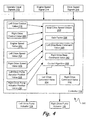
- FIG. 4 illustrates a load management schematic block diagram 200 and FIG. 5 illustrates a flow chart 300 detailing a system and method, respectively, for providing engine load management according to one illustrative embodiment.
- Controller 112 is configured to execute a control algorithm 202.
- Control algorithm 202 receives a plurality of input values, which will be discussed below. Based upon those input values, control algorithm 202 calculates left and right pump actuator command values 234 and 236, which are indicative of control signals to be provided to control left and right drive pump actuators 124 and 126. It is to be understood that control algorithm 202 is directly related to the calculation of the left and right drive command values 234 and 236. For the purposes of this discussion, it should be recognized that controller 112 can perform other tasks and execute other algorithms than the control algorithm 202, even as is related to the control of left and right drive pump actuators 124 and 126.
- Control algorithm 202 first receives a left drive control input 218 and a right drive control input 220 indicative of a desired wheel speed for the left and right sides of the power machine 10. This is indicated by block 302 of FIG. 5.
- the left drive control input 218 and the right drive control input 220 are provided by reading the one or more operator inputs 110. Based on these drive control values, the control algorithm 202 calculates left and right drive base command values 240 and 242. It should be understood that these drive base command values represent calculated values located within controller 112 based upon the signals received from the operator inputs 110.
- the actual calculation of the left and right drive base command values 240 and 242 can be done in any manner.
- the result of the calculations is, in one illustrative embodiment, left and right drive base command values 240 and 242 that are indicative of an input from the operator regarding the desired wheel speed of the left and right wheels 108 of the power machine 10.
- the left and right drive base command values 240 and 242 may include adjustment to account for any control curve that may be applied to the left and right drive control values 218 and 220.
- the input signals 110 may be filtered to reduce the introduction of noise into the left and right drive control values 218 and 220.
- the control algorithm 202 also receives a number of values related to drive system parameters. This is indicated by block 304.
- the control algorithm 202 receives an engine speed input value 222 indicative of an engine speed signal 214 received from the engine speed sensor 114 located on the power machine 10.
- the control algorithm 202 also receives left and right drive speed values 224 and 226 indicative of the signals 216 received from the drive speed sensors 116 measuring, in one illustrative embodiment, the actual speed of the left and right wheels 14 of power machine 10.
- control algorithm 202 receives a left drive pump actuator position value 228 and a right drive pump actuator position value 230, which are indicative of the position of the left and right drive pump actuators 124 and 126.
- the left and right drive pump actuator position values 228 and 230 can provide feedback information to determine whether the left and right drive pump actuators 124 and 126 are in a desired position.
- the control algorithm 202 may receive only some of these values. As one illustrative example, the control algorithm may not receive the left and right drive pump actuator position values 228 and 230. As another illustrative example, the control algorithm 202 may receive only the engine speed input value 222.
- the control algorithm 202 determines the ideal drive speeds 232 for the left and right wheels.
- the ideal drive speeds 232 are a function of the engine speed of the vehicle and the left and right drive control values 218 and 220.
- control algorithm 202 accesses previously stored ideal drive speeds 232.
- the ideal drive speeds 232 includes information that provides an ideal drive speed given a particular drive pump control value and at the given engine speed.
- the ideal drive speeds 232 are provided based on the inputs of the left drive control value 218 and the right drive control value 220 as well as the engine speed value 222.
- the ideal drive speeds 232 can be calculated or provided in a previously stored lookup table.
- the control algorithm compares the left and right drive speed values 224 and 226 to the ideal drive speeds 232. This is indicated by block 308.
- the control algorithm 202 calculates left side and right side load values, which is indicated by block 310.
- the load values have an inverse relationship to the engine speed value 222. Thus, as the engine speed of the power machine decreases, the load value will increase.
- the actual engine speed is compared to an optimum engine speed, which, in one illustrative embodiment, is the engine speed at which the engine achieves peak torque.
- the control algorithm 202 provides an appropriate left drive command value 234 and right drive command value 236.
- the left and right drive command values 234 and 236 are indicative of desired actuation of the left and right drive pump actuators 124 and 126. This is illustrated by block 312 in FIG. 5. Controller 112 can then send a signal to cause the left and right drive pump actuators 124 and 126 to a position indicated by the left and right drive command values 234 and 236.
- FIG. 6 illustrates a detailed description of block 312 of FIG. 5.
- control algorithm 202 To determine the appropriate command level to send to the left and right pump actuators, control algorithm 202 first determines the maximum load value. This is shown in block 314.
- the maximum load value in one illustrative embodiment, is the larger of the left and right load value that were previously calculated. Alternatively, other methods can be used to determine the maximum load value. For example, the average of the left and right load values could be used or the minimum of the left and right load values could be used. These are but two other illustrative examples that are not meant to be limiting.
- the control algorithm 202 calculates a gain factor 238 as is indicated by block 316.
- the gain factor 238 is calculated by accessing previously stored gain factor data as compared to the maximum load value. Alternatively, calculations can be made based on a formula to determine a gain factor.
- FIG. 7 provides a curve 400 that is a representative gain factor 238 plotted as a function of a drive command signal against a relative load applied against the engine 102.
- the left and right drive command values 234 and 236 are calculated as a function of the left and right drive base command values 240 and 242 and the gain factor 228. This is indicated by block 318.
- the left and right drive base command values 240 and 242 are multiplied by the gain factor 238 to arrive at the left and right drive command values 234 and 236.
- the gain factor has a value between zero and one. Thus, when the maximum load is zero or below a threshold value 402, the gain factor 238 is 1 and the left and right drive command values 234 and 236 equal the left and right drive base command values 240 and 242, respectively.
- the gain factor 238 decreases as is shown in curve 400. Once the gain has been determined and applied to the left and right control inputs, the gain adjusted signal is provided to the left and right outputs. This is indicated by block 320. Other calculations can be made to determine the drive command values 234 and 236 besides multiplying the gain factor 238 against the left and right drive base command values 240 and 242. In addition, in some illustrative embodiments, a gain factor 238 can have a different value for the left and right sides of the power machine 10. Of course, a power machine that is not a skid steer loader may have only a single drive command value and a single gain factor.
- the system described above provides several important advantages. For example, by reducing the output to left and right drive pump actuators, it is possible to reduce the likelihood that the engine of the power machine will stop during operation of the machine.
- the engine load management system described above provides for a way to improve the efficiency of the machine. In such situation, the machine will operate at peak efficiency, thereby providing maximum work effort without having subsequent drop-off and engine speed. Thus, an operator can operate the machine without having to adjust its control signals for perceived or actual load changes.
Landscapes
- Engineering & Computer Science (AREA)
- Mining & Mineral Resources (AREA)
- Civil Engineering (AREA)
- General Engineering & Computer Science (AREA)
- Structural Engineering (AREA)
- Automation & Control Theory (AREA)
- Chemical & Material Sciences (AREA)
- Combustion & Propulsion (AREA)
- Transportation (AREA)
- Mechanical Engineering (AREA)
- Operation Control Of Excavators (AREA)
- Control Of Vehicle Engines Or Engines For Specific Uses (AREA)
Abstract
Description
- The present discussion is related to power machines. More particularly, the present discussion is related to providing a propelling force to cause power machines to move. Power machines such as skid steer loaders, tracked vehicles, mini-excavators, utility vehicles, wheel loaders and the like have high utility in construction, landscaping, agriculture, and many other types of applications. Power machines of this type have a power source such as an engine that supplies a power that can cause the power machine to be propelled under the control of an operator. In addition, many power machines of this type utilize tools such as buckets to engage in activities such as earth moving. Digging often involves engaging materials that provide significant resistance, which in turn applies a load onto the power source of the power machine. The applied load can result in reduced performance of the power machine because of loss of power from the power source.
- In one illustrative embodiment, a method of controlling a drive system for a power machine having an engine is discussed. The method includes the steps of receiving a control signal and calculating a base output value based on the control signal. The method further includes compensating the base output value for a load applied to the engine. A signal indicative of the compensated output value is then provided to a drive component.
- In another illustrative embodiment, a power machine having an engine and a drive system including an axle with a rotatable member is discussed. The drive system is coupled to the engine. The power machine includes an operator control device that is configured to provide an input signal. The input signal is indicative of a desired rotational speed of the rotational member of the axle. The power machine also includes an engine speed sensor configured to provide an engine speed signal indicative of the speed of the engine. A drive system component is operably coupled to the axle. The drive system component has an actuation device capable of receiving an actuation signal to cause the actuation device to be actuated. The power machine also includes a controller. The controller is configured to receive the input signal and the engine speed signal. The controller provides the actuation signal to cause the drive system component to supply power to move the rotatable member of the axle based at least in part upon the engine speed signal.
- In still another illustrative embodiment, a drive system for a power machine that has an engine is discussed. The drive system includes a controller configured to receive an engine speed signal indicative of the speed of the engine and first and second rotatable axles. The drive system also includes first and second drive control mechanisms that are operably coupled to the engine. The first drive control mechanism has a first actuation device configured to receive a first actuation signal. The second drive control mechanism has a second actuation device configured to receive a second actuation signal. The controller provides first and second actuation signals to the first and second actuation devices, each of which are functions of the engine speed signal.
- This Summary is provided to introduce a selection of concepts in a simplified form that are further described below in the Detailed Description. This Summary is not intended to identify key features or essential features of the claimed subject matter, nor is it intended to be used as an aid in determining the scope of the claimed subject matter.
-
- FIG. 1 is a side elevation view of a power machine of the type in which an engine load management system discussed herein might be useful.
- FIG. 2 is block diagram illustrating a drive system for the power machine of FIG. 1 configured to provide engine load management according to one illustrative embodiment.
- FIG. 3 is a more detailed block diagram of the drive system of FIG. 2.
- FIG. 4 is a block diagram illustrating the inputs to a control algorithm for providing command values to control power components in the drive system of FIG. 3.
- FIG. 5 is a functional block diagram illustrating a method of providing engine load management according to one illustrative embodiment.
- FIG. 6 is a functional block diagram providing additional detail of the method of FIG. 5.
- FIG. 7 is a chart illustrating a representative gain control function for a drive system of a power machine for managing engine load for a power machine according to one illustrative embodiment.
- While the above-identified figures set forth one or more illustrative embodiments, other embodiments are also contemplated, as noted herein. In all cases, concepts presented herein describe the embodiments by way of representation and not by limitation. It should be understood that numerous other modifications and embodiments can be devised by those skilled in the art which fall within the scope and spirit of the principles of the discussion herein.
- FIG. 1 illustrates a
power machine 10 of the type in which an engine load management system can be usefully employed.Power machine 10 includes aframe 12 that is supported bywheels 14.Power machine 10 has an engine (not shown in FIG. 1) that applies power to a drive system (not shown in FIG. 1), which in turn supplies power to thewheels 14 causingpower machine 10 to move under the control of an operator. Examples of suitable drive systems forpower machine 10 will be discussed in more detail below.Frame 12 supports acab 16, which defines an operating compartment. - An operator can be located inside the
cab 16 and control thepower machine 10 by manipulating control devices (not shown in FIG. 1) located therein to send operator input signals to the drive system. Although thepower machine 10 is shown having a plurality ofwheels 14, it should be appreciated thatpower machine 10 need not have wheels. As one alternative example,power machine 10 can be equipped with one or more tracks that are configured to engage a supporting surface, such as ground, to propel the power machine over the supporting surface. -
Power machine 10, as illustrated in FIG. 1, further includes alift arm 18.Lift arm 18 is coupled toframe 12 atpivot point 26.Actuator 20 is coupled to theframe 12 atfirst pivot point 22 and the lift arm atsecond pivot point 24.Actuator 20, of thepower machine 10 shown in FIG. 1 is a hydraulic cylinder, although other suitable types of actuators may be used. Asingle lift arm 18 is shown in FIG. 1, but it is to be understood that asimilar lift arm 18 andcorresponding actuator 20 may be positioned on the opposite side of the cab and similarly attached toframe 12. Further, it should be understood that such a lift arm may be coupled to thelift arm 18 shown in FIG. 1 via a cross-member (not shown) extending between and attached to each of thelift arms 18. -
Power machine 10 further includes anattachment interface 28, which is rotatably coupled to thelift arm 18 aboutattachment point 30. One or more tilt actuators (not shown) are coupled to theattachment interface 28 and the one or more lift arms 18 (or the cross-member therebetween). Actuation of the one or more tilt actuators causes theattachment interface 28 to rotate about theattachment point 30 in a direction shown byarrow 38.Attachment interface 28 is configured to engage and be attached to a variety of different work implements such as a bucket, a planer, a post-hole auger, and the like. By utilizing the various attachments available to be connected to thepower machine 10 atattachment interface 28, thepower machine 10 provides a desirable and suitable tool to accomplish a number of different types of tasks. For example, by attaching a bucket (not shown) topower machine 10, an operator is capable of digging earth, moving material, and any number of tasks related to landscaping, construction, material removal, or any number of different types of applications. - The
power machine 10 illustrated in FIG. 1 is a skid steer loader. A skid steer loader has rigid axles coupled to each of thewheels 14. Thewheels 14 on each side of the skid steer loader are operably coupled to each so that they operate in tandem. Each side of the skid steer loader has its own drive system, which supplies power to the wheels on that particular side. Steering is accomplished by controlling the drive system of one or both sides of the machine to cause the machine to skid on the supporting surface in a direction that is desired by the operator. - As one illustrative example, an operator wishing to move or turn
power machine 10 to the right may cause thewheels 14 on the left side of thepower machine 10 to move in a forward direction. In addition, the operator can cause thewheels 14 on the right side to move in a reverse direction, not at all, or in a forward direction at a lesser rate of speed than theleft side wheels 14. The net effect is a forward force applied to the left side of thepower machine 10 that is greater than the forward force applied to the right hand side. As a result, thepower machine 10 will skid on itswheels 14 to the right. This is just one non-limiting example of how a skid steer loader can be operated. Other steering operations can be employed to accomplish a right turn, for example. Although the illustrative example of thepower machine 10 in FIG. 1 is a skid steer loader, the discussion provided in this document need not be limited to skid steer loaders. Alternatively, and without limitation, the discussion herein can be applied to other power machines such as wheeled loaders with a front or rear steerable axle, excavators, utility vehicles, all-wheel steer vehicles, tracked loaders, or any other similar power machine. - FIG. 2 illustrates a block diagram of a
drive system 100 for providing a propelling power to causepower machine 10 to move in accordance with one illustrative embodiment.Drive system 100 receives power from anengine 102 that is located within thepower machine 10.Engine 102 is coupled to adrive mechanism 104 to provide thedrive mechanism 104 with an input power source.Drive mechanism 104 receives drive control signals indicated byblock 106 from an operator to control thedrive mechanism 104.Drive mechanism 104 then provides an output to wheels 108 (or alternatively, for example, tracks) to cause thepower machine 10 to move. - In one embodiment, the
drive mechanism 104 includes a hydraulic or hydrostatic drive system. Other types of drive mechanisms can be used without departing from the spirit and scope of the discussion.Drive control 106 provides drive signals to thedrive mechanism 104 in response to manipulation by an operator of one or more control devices such as levers, buttons, dials, pedals, joysticks, or any other type of actuable control device that may be appropriate. As thepower machine 10 is illustratively described as a skid steer loader, steering thepower machine 10, as well as propelling, is accomplished by the operation of thedrive mechanism 104. In alternative embodiments, steering control devices that are separate from the drive mechanism in a particular power machine may or may not be relevant to the control of that drive mechanism. - As discussed above,
power machine 10 can utilize various attachments to accomplish a wide variety of tasks in different applications. One particular application mentioned above is the use of a bucket for digging. When an operator is operating thepower machine 10 for the purposes of digging a hole, for example, the resistance that thepower machine 10 can encounter from moving into and engaging tightly compacted earth causes the power to slow down and also transfers a load onto theengine 102. - It is desirable to operate the
power machine 10 at an engine speed at which theengine 102 supplies the maximum torque to thedrive mechanism 104. If an operator manipulates control devices to cause thedrive mechanism 104 to attempt to supply too much power to thewheels 108 in a loaded condition, the resultant load will cause theengine 102 to slow down and deliver less power to the drive mechanism. Operating thepower machine 10 in such a manner results in reduced efficiency of operation. Furthermore, if the speed of theengine 102 slows below a certain threshold level, the engine will reach a point where it will shut down and stop operating, even if the load is removed. An operator can restart the engine, but repeated episodes of having theengine 102 stop and be restarted also results in a loss of efficiency of operation of thepower machine 10. - An operator can reduce the load on
engine 102 by manipulating the control devices to reduce the drive signals provided bydrive control 106 to thedrive mechanism 104, which in turn causes the drive mechanism to reduce the power supplied to thewheels 108. By reducing the power supplied to thewheels 108, the load on theengine 102 is reduced. In situations where there is an extreme load on theengine 102, if the operator does so before the engine slows to the point where it cannot recover, theengine 102 will recover and begin to operate at a potentially more efficient speed. As the load applied to theengine 102 varies, the operator may have to vary his or her manipulation of control devices to prevent theengine 102 from stopping. In addition, it should be appreciated that by manually varying the control devices to control the drive mechanism, the operator may not operate thepower machine 10 at an optimum efficiency. By providing adrive system 100 that compensates for increased load on the engine, thedrive system 100 can operate thepower machine 10 with an efficient load on theengine 102. Therefore, theengine 102 can operate at an optimum speed and supply an optimum torque so that thepower machine 10 can accomplish work efficiently. - FIG. 3 illustrates the
drive system 100, which is configured to manage a load on its engine, in more detail according to one illustrative embodiment.Drive control 106 includes acontroller 112 that is configured to receive one ormore operator inputs 110.Operator inputs 110, in one illustrative embodiment, include a pair of inputs, one for the left-hand side of thepower machine 10 and another for the right-hand side of thepower machine 10. Theoperator input 110 corresponding to the left-hand side of thepower machine 10 provides a signal indicative of a desired speed and direction in which the wheels on the left-hand side should be propelled. Similarly, theoperator input 110 corresponding to the right-hand side of thepower machine 10 provides a signal indicative of a desired speed and direction in which the wheels on the right-hand side should be propelled. Other configurations ofoperator inputs 110 can be provided. As just one illustrative example, a drive input can be provided to indicate the desired speed and direction (forward or reverse) in whichpower machine 10 should be propelled and a steering input can be provided to indicate whether and how much the power machine should be turned.Controller 112 can be any type of logic device capable of receiving inputs and providing output signals to control various devices. For example,controller 112 can be a microprocessor-based device. -
Controller 112 can also be configured to receive signals indicative of operating conditions of various systems in thepower machine 10. For example,controller 112 receives a signal from anengine speed sensor 114, which is indicative of the rotational speed of the engine.Engine speed sensor 114 can be any type of device capable of measuring the rotation of an engine. For example,engine speed sensor 114 can be a magnetic pickup capable of providing a signal indicative of the presence or absence of a tooth on a flywheel that is rotating in close proximity to theengine speed sensor 114. - In addition,
controller 112 is configured to receive inputs from one or moredrive speed sensors 116. The one or moredrive speed sensors 116, in one illustrative embodiment, are each positioned to measure the rotational speed of one of thewheels 108. Alternatively, one or more of thedrive speed sensors 116 can be positioned to measure the rotation of one of the axles that is rigidly coupled to one of thewheels 108. - As discussed above,
power machine 10 is a skid steer loader, which has thewheels 108 on each of the left and right hand sides of thepower machine 10 driven together. Thus, a singledrive speed sensor 116 measuring the speed of awheel 108 on the left-hand side of the machine could provide information indicative of the wheel speed of each of thewheels 108 on the left-hand side of the machine. Similarly, adrive speed sensor 116 on the right-hand side of the machine measuring the wheel speed of one of thewheels 108 can provide information indicative of the wheel speed of both of thewheels 108 on the right-hand side of thepower machine 10. - In alternative embodiments, other configurations of
drive speed sensors 116 may be provided. For example, adrive speed sensor 116 may be provided for eachwheel 108. Alternatively, a singledrive speed sensor 116 may be provided for the rear wheels and/or the front wheels, in embodiments where the front and/or rear wheels operate in tandem. Alternatively still, thedrive speed sensors 116 may measure the speed of an axle in the case of a tracked machine. Alternatively still,controller 112 may not receive signals indicative of the wheel speed from any wheel speed sensors. - Referring again to FIG. 3, the
drive mechanism 104 of the illustrative embodiment includes aleft drive pump 120 and aright drive pump 122, which provide hydraulic power for the left and right sides of thedrive mechanism 104, respectively.Left drive pump 120 has anactuation mechanism 124, which, when actuated, causes oil to flow from theleft drive pump 120 to aleft drive motor 128. Theactuation mechanism 124 is a variable position device, which can cause oil flow from theleft drive pump 120 to theleft drive motor 128 to vary in rate and direction, depending on the position of theactuation mechanism 124. In one illustrative embodiment, a position sensor 144 is provided to measure the position of theactuation mechanism 124. Position sensor 144 can provide a position feedback signal tocontroller 112 that can be used to determine the signal sent to theactuation mechanism 124. - As will be discussed in more detail below, providing flow in one direction will cause an
output shaft 140 on theleft drive motor 128 to turn in one direction. Providing flow in the other direction will cause theoutput shaft 140 on theleft drive motor 128 to turn in the other direction. By varying the position of theactuation mechanism 124, the rate and direction of flow of hydraulic oil from theleft drive pump 120 to theleft drive motor 128 can be controlled. Thus, rotation of theoutput shaft 140 ofleft drive motor 128 is controlled. Similarly,right drive pump 122 has anactuation mechanism 126, which can be actuated in various positions to control the direction and rate of oil flow to aright drive motor 130. Aposition sensor 146, in one illustrative embodiment, provides a position signal tocontroller 112. - The
output shaft 140 of theleft drive motor 128 is operably coupled to leftfront axle 132 and leftrear axle 134. Leftfront axle 132 is in turn coupled to awheel 108 and leftrear axle 134 is likewise coupled to awheel 108. The operable coupling of theleft drive motor 128 to both the leftfront axle 132 and the leftrear axle 134 can be accomplished, in one illustrative example, by an arrangement of chains and sprockets that engage theoutput shaft 140 of the lefthydraulic motor 128 and the leftfront axle 132 and the leftrear axle 134. In an alternative embodiment, a pair ofleft drive motors 128 are drive by theleft drive pump 120. One of the left drive motors is coupled to the leftfront axle 132 and the other of which is coupled to the leftrear axle 134. - The
output shaft 140 of theleft drive motor 128 is thus capable of driving the leftfront axle 132 and the leftrear axle 134 in a forward or reverse direction depending upon its direction of rotation. Of course, as described above, the direction of rotation of theoutput shaft 140 of theleft drive motor 128 is controlled by the direction of flow of oil from theleft drive pump 120 to theleft drive motor 128. - Similarly,
right drive pump 122 provides hydraulic oil to theright drive motor 130 in one of two directions. Anoutput shaft 142 of theright drive motor 130 then is coupled to rightfront axle 136 and rightrear axle 138. Rightfront axle 136 and rightrear axle 138 are in turn coupled towheels 108 on the right-hand side of the machine. Alternatively, too, a pair ofright drive motors 130 can be incorporated, one of which is coupled to the rightfront axle 136 and the other of which is coupled to the leftrear axle 138. - FIG. 4 illustrates a load management schematic block diagram 200 and FIG. 5 illustrates a
flow chart 300 detailing a system and method, respectively, for providing engine load management according to one illustrative embodiment.Controller 112 is configured to execute acontrol algorithm 202.Control algorithm 202 receives a plurality of input values, which will be discussed below. Based upon those input values,control algorithm 202 calculates left and right pumpactuator command values drive pump actuators control algorithm 202 is directly related to the calculation of the left and right drive command values 234 and 236. For the purposes of this discussion, it should be recognized thatcontroller 112 can perform other tasks and execute other algorithms than thecontrol algorithm 202, even as is related to the control of left and rightdrive pump actuators -
Control algorithm 202 first receives a leftdrive control input 218 and a right drive control input 220 indicative of a desired wheel speed for the left and right sides of thepower machine 10. This is indicated byblock 302 of FIG. 5. The leftdrive control input 218 and the right drive control input 220 are provided by reading the one ormore operator inputs 110. Based on these drive control values, thecontrol algorithm 202 calculates left and right drive base command values 240 and 242. It should be understood that these drive base command values represent calculated values located withincontroller 112 based upon the signals received from theoperator inputs 110. - The actual calculation of the left and right drive base command values 240 and 242 can be done in any manner. The result of the calculations is, in one illustrative embodiment, left and right drive base command values 240 and 242 that are indicative of an input from the operator regarding the desired wheel speed of the left and
right wheels 108 of thepower machine 10. For example, the left and right drive base command values 240 and 242 may include adjustment to account for any control curve that may be applied to the left and rightdrive control values 218 and 220. In addition, the input signals 110 may be filtered to reduce the introduction of noise into the left and rightdrive control values 218 and 220. - The
control algorithm 202 also receives a number of values related to drive system parameters. This is indicated by block 304. Thecontrol algorithm 202 receives an enginespeed input value 222 indicative of anengine speed signal 214 received from theengine speed sensor 114 located on thepower machine 10. Thecontrol algorithm 202 also receives left and right drive speed values 224 and 226 indicative of thesignals 216 received from thedrive speed sensors 116 measuring, in one illustrative embodiment, the actual speed of the left andright wheels 14 ofpower machine 10. - In addition, the
control algorithm 202 receives a left drive pumpactuator position value 228 and a right drive pumpactuator position value 230, which are indicative of the position of the left and rightdrive pump actuators drive pump actuators control algorithm 202 may receive only some of these values. As one illustrative example, the control algorithm may not receive the left and right drive pump actuator position values 228 and 230. As another illustrative example, thecontrol algorithm 202 may receive only the enginespeed input value 222. - As shown in
block 306, thecontrol algorithm 202 then determines the ideal drive speeds 232 for the left and right wheels. In one illustrative embodiment, the ideal drive speeds 232 are a function of the engine speed of the vehicle and the left and rightdrive control values 218 and 220. In one illustrative embodiment,control algorithm 202 accesses previously stored ideal drive speeds 232. The ideal drive speeds 232 includes information that provides an ideal drive speed given a particular drive pump control value and at the given engine speed. Thus, the ideal drive speeds 232 are provided based on the inputs of the leftdrive control value 218 and the right drive control value 220 as well as theengine speed value 222. The ideal drive speeds 232 can be calculated or provided in a previously stored lookup table. - Next, the control algorithm compares the left and right drive speed values 224 and 226 to the ideal drive speeds 232. This is indicated by
block 308. Left and right drive speed differences are calculated that indicate a difference between the ideal drive speed and the drive speed values as follows:

where DSD is the drive speed difference, IDS is the ideal drive speed and DSV is the actual drive speed. Becausepower machine 10 in the illustrative embodiment is a skid steer loader, the ideal and actual drive speeds for the left side may differ from the ideal and actual drive speeds for the right side. Other types of power machines may have only one ideal drive speed number and all wheels on the power machine will be compared against the one ideal drive speed value. Only those situations where the actual drive speed is less than the ideal drive speed are relevant to any engine load management situations. Therefore, if either (or both) of the Left DSD or Right DSD is less than zero, the DSD is set to zero. - After the
control algorithm 202 has determined the left and right drive speed differences, thecontrol algorithm 202 calculates left side and right side load values, which is indicated byblock 310. The load values have an inverse relationship to theengine speed value 222. Thus, as the engine speed of the power machine decreases, the load value will increase. The actual engine speed is compared to an optimum engine speed, which, in one illustrative embodiment, is the engine speed at which the engine achieves peak torque. The left load and right load values are calculated as follows:

where OES is the optimum engine speed and AES is theengine speed value 222. - Once the left and right load values are calculated, the
control algorithm 202 provides an appropriate leftdrive command value 234 and rightdrive command value 236. The left and right drive command values 234 and 236 are indicative of desired actuation of the left and rightdrive pump actuators block 312 in FIG. 5.Controller 112 can then send a signal to cause the left and rightdrive pump actuators - FIG. 6 illustrates a detailed description of
block 312 of FIG. 5. To determine the appropriate command level to send to the left and right pump actuators,control algorithm 202 first determines the maximum load value. This is shown inblock 314. The maximum load value, in one illustrative embodiment, is the larger of the left and right load value that were previously calculated. Alternatively, other methods can be used to determine the maximum load value. For example, the average of the left and right load values could be used or the minimum of the left and right load values could be used. These are but two other illustrative examples that are not meant to be limiting. - Once the maximum load value has been determined, the
control algorithm 202 calculates again factor 238 as is indicated byblock 316. In one illustrative embodiment, thegain factor 238 is calculated by accessing previously stored gain factor data as compared to the maximum load value. Alternatively, calculations can be made based on a formula to determine a gain factor. FIG. 7 provides acurve 400 that is arepresentative gain factor 238 plotted as a function of a drive command signal against a relative load applied against theengine 102. - Once the
gain factor 238 has been obtained, the left and right drive command values 234 and 236 are calculated as a function of the left and right drive base command values 240 and 242 and thegain factor 228. This is indicated byblock 318. In one illustrative embodiment, the left and right drive base command values 240 and 242 are multiplied by thegain factor 238 to arrive at the left and right drive command values 234 and 236. For example, in one illustrative embodiment, the gain factor has a value between zero and one. Thus, when the maximum load is zero or below athreshold value 402, thegain factor 238 is 1 and the left and right drive command values 234 and 236 equal the left and right drive base command values 240 and 242, respectively. As the load increases, thegain factor 238 decreases as is shown incurve 400. Once the gain has been determined and applied to the left and right control inputs, the gain adjusted signal is provided to the left and right outputs. This is indicated byblock 320. Other calculations can be made to determine the drive command values 234 and 236 besides multiplying thegain factor 238 against the left and right drive base command values 240 and 242. In addition, in some illustrative embodiments, again factor 238 can have a different value for the left and right sides of thepower machine 10. Of course, a power machine that is not a skid steer loader may have only a single drive command value and a single gain factor. - The system described above provides several important advantages. For example, by reducing the output to left and right drive pump actuators, it is possible to reduce the likelihood that the engine of the power machine will stop during operation of the machine. In addition, the engine load management system described above provides for a way to improve the efficiency of the machine. In such situation, the machine will operate at peak efficiency, thereby providing maximum work effort without having subsequent drop-off and engine speed. Thus, an operator can operate the machine without having to adjust its control signals for perceived or actual load changes.
- Although the discussion has been focused upon illustrative embodiments, workers skilled in the art will recognize that changes may be made in form and detail without departing from the spirit and the scope of the discussion.
- Attention is directed to all papers and documents which are filed concurrently with or previous to this specification in connection with this application and which are open to public inspection with this specification, and the contents of all such papers and documents are incorporated herein by reference.
- All of the features disclosed in this specification (including any accompanying claims, abstract and drawings), and/or all of the steps of any method or process so disclosed, may be combined in any combination, except combinations where at least some of such features and/or steps are mutually exclusive.
- Each feature disclosed in this specification (including any accompanying claims, abstract and drawings) may be replaced by alternative features serving the same, equivalent or similar purpose, unless expressly stated otherwise. Thus, unless expressly stated otherwise, each feature disclosed is one example only of a generic series of equivalent or similar features.
- The invention is not restricted to the details of the foregoing embodiment(s). The invention extends to any novel one, or any novel combination, of the features disclosed in this specification (including any accompanying claims, abstract and drawings), or to any novel one, or any novel combination, of the steps of any method or process so disclosed.
Claims (20)
- A method of controlling a drive system for a power machine having an engine, comprising:receiving a control signal and calculating a base output value based on the control signal;compensating the base output value for a load applied to the engine to create a compensated output value; andproviding a signal indicative of the compensated output value to a drive component.
- The method of claim 1, wherein the step of compensating the base output value comprises:receiving an engine speed signal indicative of the engine speed; andcalculating an engine speed value as a function of the engine speed signal.
- The method of claim 2, wherein the step of compensating the base output value comprises:comparing the engine speed value with a desired engine speed value.
- The method of claim 3 the step of compensating the base output value comprises:determining a gain factor based on the engine speed value and the desired engine speed value.
- The method of claim 1, and further comprising:receiving a drive speed signal indicative of the rotational speed of an axle on the power machine; andcalculating a drive speed value as a function of the drive speed signal.
- The method of claim 5, wherein the step of receiving a drive speed signal includes receiving a signal from a sensor configured to measure the rotational speed of a wheel rigidly coupled to the axle.
- The method of claim 5, wherein the step of compensating the base output value comprises:calculating a gain as a function of the drive speed value.
- The method of claim 5, wherein the step of compensating the base output value comprises:calculating a gain as a function of the drive speed value and a desired drive speed value.
- The method of claim 5, wherein the step of compensating the base output value comprises:receiving an engine speed signal indicative of the engine speed;calculating an engine speed value based on the engine speed signal; andcalculating a gain as a function of the drive speed value and the engine speed value.
- The method of claim 1, wherein the step of compensating the base output value comprises:calculating a gain; andmultiplying the base output value by the gain.
- The method of claim 1, wherein the step of providing a signal to a drive component includes providing the signal to a drive component operably coupled to more than one wheel on one side of the power machine.
- A power machine having an engine and a drive system including an axle with a rotatable member coupled to the engine, the power machine comprising:an operator control device configured to provide an input signal indicative of a desired rotational speed of the rotational member of the axle;an engine speed sensor configured to provide an engine speed signal indicative of the speed of the engine;a drive system component operably coupled to the axle and having an actuation device capable of receiving an actuation signal to cause the actuation device to be actuated; anda controller configured to receive the input signal and the engine speed signal and provide the actuation signal to cause the drive system component to supply power to move the rotatable member of the axle based at least in part upon the engine speed signal.
- The power machine of claim 12, and further comprising:a wheel fixedly coupled to the rotatable member of the axle;a wheel speed sensor configured to provide a wheel speed signal indicative of the rotational speed of the wheel; andwherein the controller is configured to receive the wheel speed signal and wherein the actuation signal is based at least in part on the wheel speed signal.
- The power machine of claim 13, wherein the controller is configured to compare the wheel speed signal to a desired wheel speed signal and wherein the actuation signal is based at least in part on difference between the wheel speed signal and the desired wheel speed signal.
- The power machine of claim 12, wherein the controller is configured to make a comparison between the engine speed signal and a desired engine speed value and wherein the actuation signal is based at least in part upon the comparison.
- A drive system for a power machine having an engine, comprising:a controller configured to receive an engine speed signal indicative of the speed of the engine;first and second rotatable axles;a first drive control mechanism operably coupled to the engine and the first axle and having a first actuation device configured to receive a first actuation signal;a second drive control mechanism operably coupled to the engine and the second axle and having a second actuation device configured to receive a second actuation signal;wherein the controller provides the first and second actuation signals to the first and second actuation devices, and wherein the first and second actuation signals are determined as functions of the engine speed signal.
- The drive system of claim 16, wherein the controller is configured to provide the actuation signal to the actuation device of the first drive control mechanism to cause the first axle to rotate at a different speed than the second axle.
- The drive system of claim 16, and further comprising:first and second drive speed sensors configured to provide first and second drive speed signals;wherein the controller is configured to receive the first and second drive speed signals; and
wherein the first and second actuation signals are based at least in part upon the first and second drive speed signals, respectively. - The drive system of claim 18, wherein the controller determines a first desired drive speed and wherein the first actuation signal is based in part upon a difference between the first drive speed signal and the first desired drive speed.
- The drive system of claim 18, wherein the controller determines a second desired drive speed and wherein the second actuation signal is based in part upon a difference between the second drive speed signal and the second desired drive speed.
Applications Claiming Priority (1)
| Application Number | Priority Date | Filing Date | Title |
|---|---|---|---|
| US11/590,437 US8041492B2 (en) | 2006-10-31 | 2006-10-31 | Engine load management for power machines |
Publications (2)
| Publication Number | Publication Date |
|---|---|
| EP1918463A2 true EP1918463A2 (en) | 2008-05-07 |
| EP1918463A3 EP1918463A3 (en) | 2016-05-18 |
Family
ID=38984428
Family Applications (1)
| Application Number | Title | Priority Date | Filing Date |
|---|---|---|---|
| EP07118513.6A Withdrawn EP1918463A3 (en) | 2006-10-31 | 2007-10-15 | Engine load management for power machines |
Country Status (4)
| Country | Link |
|---|---|
| US (1) | US8041492B2 (en) |
| EP (1) | EP1918463A3 (en) |
| CN (1) | CN101173634B (en) |
| CA (1) | CA2608563A1 (en) |
Cited By (2)
| Publication number | Priority date | Publication date | Assignee | Title |
|---|---|---|---|---|
| WO2010046723A1 (en) * | 2008-10-23 | 2010-04-29 | Volvo Compact Equipment Sas | Skid steer machine with automatic operating ratio change system |
| US8041492B2 (en) * | 2006-10-31 | 2011-10-18 | Clark Equipment Company | Engine load management for power machines |
Families Citing this family (9)
| Publication number | Priority date | Publication date | Assignee | Title |
|---|---|---|---|---|
| US20090198414A1 (en) * | 2008-01-31 | 2009-08-06 | Caterpillar Inc. | Operator interface for controlling a vehicle |
| IT1396698B1 (en) * | 2009-11-11 | 2012-12-14 | Nilfisk Advance Spa | PERFECT VEHICLE FOR THE TREATMENT AND CLEANING OF FLOORS AND SOILS |
| JP5533344B2 (en) * | 2010-06-29 | 2014-06-25 | 日産自動車株式会社 | Driving force distribution device |
| JP5665652B2 (en) * | 2011-05-19 | 2015-02-04 | 日立建機株式会社 | Information management device for construction machinery |
| US8600621B2 (en) | 2011-12-20 | 2013-12-03 | Caterpillar Inc. | System and method for controlling slip |
| JP5805217B2 (en) * | 2012-01-11 | 2015-11-04 | 日立建機株式会社 | Hydraulic closed circuit drive |
| JP6080458B2 (en) * | 2012-09-28 | 2017-02-15 | 株式会社アイチコーポレーション | Crawler type traveling vehicle |
| US9371898B2 (en) * | 2012-12-21 | 2016-06-21 | Cnh Industrial America Llc | Control system for a machine with a dual path electronically controlled hydrostatic transmission |
| US11788250B2 (en) | 2019-07-29 | 2023-10-17 | Great Plains Manufacturing, Inc. | Loader with improved arm path |
Family Cites Families (57)
| Publication number | Priority date | Publication date | Assignee | Title |
|---|---|---|---|---|
| US3835382A (en) * | 1971-06-29 | 1974-09-10 | E Weisbart | Vehicle performance indicator system |
| US3913680A (en) | 1972-10-25 | 1975-10-21 | Allis Chalmers | Control system for percentage of wheel slippage of a tractor |
| US4046210A (en) * | 1975-05-22 | 1977-09-06 | Eaton Corporation | Multiple drive axle assembly |
| US4086563A (en) | 1975-07-10 | 1978-04-25 | Dickey-John Corporation | Wheel slippage monitor |
| US4024710A (en) * | 1976-03-25 | 1977-05-24 | Koehring Company | Load sensing hydraulic circuit having power matching means |
| US4092789A (en) * | 1976-12-20 | 1978-06-06 | Jon Craig Arfons | Mobile directional high velocity air moving apparatus |
| US4419654A (en) | 1981-07-17 | 1983-12-06 | Dickey-John Corporation | Tractor data center |
| JPS58184345A (en) * | 1982-04-23 | 1983-10-27 | Toyota Motor Corp | Speed change gear for car |
| US4667767A (en) * | 1985-02-22 | 1987-05-26 | Dana Corporation | Four wheel drive system including disengagement means |
| US4740898A (en) | 1986-07-17 | 1988-04-26 | Deere & Company | Automatic engine/transmission control system |
| DE298232T1 (en) | 1987-06-11 | 1989-06-01 | Honda Giken Kogyo K.K., Tokio/Tokyo | DRIVE WHEEL SLIP CONTROL SYSTEM FOR VEHICLES. |
| DE3811214C2 (en) * | 1988-04-02 | 1994-04-21 | Porsche Ag | Arrangement for controlling the power transmission on at least two axles of a motor vehicle |
| US5544055A (en) * | 1994-07-29 | 1996-08-06 | Vermeer Manufacturing Company | Track trencher control system and process |
| JP3654599B2 (en) * | 1994-09-09 | 2005-06-02 | 株式会社小松製作所 | Transmission device for hydraulic drive device and transmission control method therefor |
| US5823280A (en) * | 1995-01-12 | 1998-10-20 | Nevcor, Inc. | Hybrid parallel electric vehicle |
| JP3052844B2 (en) * | 1995-11-14 | 2000-06-19 | トヨタ自動車株式会社 | Power output device, control method therefor, and drive device |
| US5948029A (en) * | 1997-02-05 | 1999-09-07 | Deere & Company | Steering control system for tracked vehicle |
| US5873427A (en) * | 1997-04-03 | 1999-02-23 | Caterpillar Inc. | Method and apparatus for controlling a load of an engine associated with a hydrostatic drive system |
| DE19820830C1 (en) * | 1998-05-09 | 1999-09-23 | Daimler Chrysler Ag | Vehicle motor control device with speed control or regulation |
| US6167979B1 (en) * | 1998-05-20 | 2001-01-02 | Cummins Engine Company, Inc. | Dynamic speed governing of a vehicle |
| US6427108B1 (en) * | 1998-07-17 | 2002-07-30 | Honda Giken Kogyo Kabushiki Kaisha | Control system for automatic vehicle transmission |
| GB2339761A (en) * | 1998-07-25 | 2000-02-09 | Bamford Excavators Ltd | Load handling apparatus |
| JP3813387B2 (en) * | 1998-07-28 | 2006-08-23 | 富士写真フイルム株式会社 | Information embedding method and apparatus, and recording medium |
| US6062332A (en) | 1998-09-08 | 2000-05-16 | Eaton Corporation | Hydrostatic vehicle drive system having improved control thereof |
| JP4709390B2 (en) * | 1999-03-15 | 2011-06-22 | デカ・プロダクツ・リミテッド・パートナーシップ | Balanced personal vehicle control |
| US6799649B2 (en) * | 1999-03-15 | 2004-10-05 | Deka Products Limited Partnership | Control of a balancing personal vehicle |
| US6206798B1 (en) * | 1999-09-03 | 2001-03-27 | Meritor Heavy Vehicle Systems, Llc | Active differential |
| US6119061A (en) * | 1999-09-30 | 2000-09-12 | Caterpillar Inc. | Method and apparatus for controlling an electro-hydraulic differential steering system |
| US6216072B1 (en) | 1999-11-23 | 2001-04-10 | Deere & Company | Hitch control system with adjustable slip response |
| JP3866479B2 (en) * | 2000-04-07 | 2007-01-10 | 株式会社デンソー | Inter-vehicle control device, recording medium |
| JP2001303990A (en) * | 2000-04-24 | 2001-10-31 | Denso Corp | Variable valve timing control device for internal combustion engine |
| JP2002071188A (en) * | 2000-08-30 | 2002-03-08 | Mitsubishi Electric Building Techno Service Co Ltd | Heat medium supply abnormality detection device |
| JP3788240B2 (en) * | 2001-01-18 | 2006-06-21 | 日産自動車株式会社 | Vehicle tracking control device |
| JP2002259160A (en) * | 2001-02-27 | 2002-09-13 | Ntt Comware Corp | Test item extraction system device, test item extraction method, recording medium storing test item extraction program, and test item extraction program |
| US6650985B2 (en) * | 2001-12-28 | 2003-11-18 | Case, Llc | Skid steer vehicle having anti-rolling system |
| JP2003274511A (en) * | 2002-03-15 | 2003-09-26 | Hitachi Ltd | Control device for vehicle generator |
| US8135531B2 (en) * | 2002-06-12 | 2012-03-13 | Nmhg Oregon, Llc | Predictive vehicle controller |
| US6852064B2 (en) * | 2002-07-18 | 2005-02-08 | Sauer-Danfoss, Inc. | Hydromechanical transmission electronic control system for high speed vehicles |
| JP3610969B2 (en) * | 2002-08-27 | 2005-01-19 | 日産自動車株式会社 | Driving force control device for four-wheel drive vehicle |
| JP4039184B2 (en) * | 2002-08-29 | 2008-01-30 | 株式会社アドヴィックス | Creep travel control device |
| JP3552710B2 (en) * | 2002-09-04 | 2004-08-11 | 日産自動車株式会社 | Vehicle driving force control device |
| JP2004157295A (en) * | 2002-11-06 | 2004-06-03 | Oki Electric Ind Co Ltd | Audio reproduction device and method of correcting performance data |
| DE502004008154D1 (en) * | 2003-05-08 | 2008-11-13 | Continental Teves Ag & Co Ohg | METHOD AND DEVICE FOR REGULATING THE DRIVING DYNAMICS OF A VEHICLE |
| JP2005180643A (en) * | 2003-12-22 | 2005-07-07 | Jatco Ltd | Control device for torque transmission system |
| EP1750821A4 (en) * | 2004-02-11 | 2008-12-10 | Mattel Inc | Remote-controlled toy vehicle having multi-mode drive mechanism |
| JP4549738B2 (en) * | 2004-05-27 | 2010-09-22 | 株式会社日立製作所 | Vehicle control system, control system, and control method |
| JP4059242B2 (en) * | 2004-11-02 | 2008-03-12 | 株式会社日立製作所 | Hybrid vehicle and control method thereof |
| JP4640044B2 (en) * | 2005-06-01 | 2011-03-02 | トヨタ自動車株式会社 | Automobile and control method thereof |
| JP4265572B2 (en) * | 2005-06-01 | 2009-05-20 | トヨタ自動車株式会社 | POWER OUTPUT DEVICE, VEHICLE MOUNTING THE SAME, AND METHOD FOR CONTROLLING POWER OUTPUT DEVICE |
| JP4616112B2 (en) * | 2005-07-25 | 2011-01-19 | 住友大阪セメント株式会社 | Cement quick setting material and cement composition |
| US7233855B1 (en) * | 2005-12-08 | 2007-06-19 | Gm Global Technology Operations, Inc. | Apparatus and method for comparing the fuel consumption of an alternative fuel vehicle with that of a traditionally fueled comparison vehicle |
| WO2007072627A1 (en) * | 2005-12-21 | 2007-06-28 | Toyota Jidosha Kabushiki Kaisha | Device for judging misfire of internal combustion engine and vehicle mounting it and method for judging misfire |
| ES2394660T3 (en) * | 2006-08-11 | 2013-02-04 | Segway Inc. | Speed limitation in electric vehicles |
| US8041492B2 (en) * | 2006-10-31 | 2011-10-18 | Clark Equipment Company | Engine load management for power machines |
| JP5084295B2 (en) * | 2007-02-09 | 2012-11-28 | 日立建機株式会社 | Pump torque control device for hydraulic construction machinery |
| US20080254941A1 (en) * | 2007-04-11 | 2008-10-16 | Jeffery Scott | Controlling the operating states of a torque converter clutch in an automatic transmission |
| JP5036460B2 (en) * | 2007-09-06 | 2012-09-26 | トヨタ自動車株式会社 | Vehicle travel control device |
-
2006
- 2006-10-31 US US11/590,437 patent/US8041492B2/en active Active
-
2007
- 2007-10-15 EP EP07118513.6A patent/EP1918463A3/en not_active Withdrawn
- 2007-10-29 CA CA002608563A patent/CA2608563A1/en not_active Abandoned
- 2007-10-31 CN CN2007101700241A patent/CN101173634B/en not_active Expired - Fee Related
Cited By (3)
| Publication number | Priority date | Publication date | Assignee | Title |
|---|---|---|---|---|
| US8041492B2 (en) * | 2006-10-31 | 2011-10-18 | Clark Equipment Company | Engine load management for power machines |
| WO2010046723A1 (en) * | 2008-10-23 | 2010-04-29 | Volvo Compact Equipment Sas | Skid steer machine with automatic operating ratio change system |
| US8478504B2 (en) | 2008-10-23 | 2013-07-02 | Volvo Compact Equipment Sas | Skid steer machine with automatic operating ratio change system |
Also Published As
| Publication number | Publication date |
|---|---|
| CA2608563A1 (en) | 2008-04-30 |
| CN101173634B (en) | 2012-12-26 |
| US8041492B2 (en) | 2011-10-18 |
| CN101173634A (en) | 2008-05-07 |
| EP1918463A3 (en) | 2016-05-18 |
| US20080103638A1 (en) | 2008-05-01 |
Similar Documents
| Publication | Publication Date | Title |
|---|---|---|
| CN101173634B (en) | Engine load management for power machines | |
| EP2746469B1 (en) | Load control for a machine with a dual path electronically controlled hydrostatic transmission | |
| EP1650418B1 (en) | Traveling-type hydraulic working machine | |
| JP5996314B2 (en) | Wheel loader and wheel loader engine control method | |
| JPWO2008146846A1 (en) | Driving force control device and driving force control method for work vehicle | |
| US20130238178A1 (en) | Power management for a drive system | |
| JP6959899B2 (en) | Wheel loader | |
| JP2006097897A (en) | Control of all-wheel-drive vehicle | |
| EP3879137B1 (en) | Hydrostatic transmission for a work vehicle provided with a hill-holder system | |
| JPH1088622A (en) | Method and apparatus for modifying feedback gain of a traction control device | |
| JPH1045014A (en) | Steering device with variable steering wheel operation angle | |
| US9291105B2 (en) | Utility vehicle horsepower management | |
| CN103765054B (en) | The fluid drive of mechanical gearbox | |
| JP4933210B2 (en) | Crawler type traveling device | |
| JP4376009B2 (en) | Control device for work vehicle | |
| US10934950B2 (en) | System and method to control powertrain during directional shift | |
| CN114402150B (en) | Displacement control device for driving motor | |
| US20260103873A1 (en) | Multifunctional transmission valve with integrated load brake function | |
| JP4376018B2 (en) | Control device for work vehicle | |
| CN114270024A (en) | Engine control system, work machine, and work machine control method |
Legal Events
| Date | Code | Title | Description |
|---|---|---|---|
| PUAI | Public reference made under article 153(3) epc to a published international application that has entered the european phase |
Free format text: ORIGINAL CODE: 0009012 |
|
| AK | Designated contracting states |
Kind code of ref document: A2 Designated state(s): AT BE BG CH CY CZ DE DK EE ES FI FR GB GR HU IE IS IT LI LT LU LV MC MT NL PL PT RO SE SI SK TR |
|
| AX | Request for extension of the european patent |
Extension state: AL BA HR MK RS |
|
| PUAL | Search report despatched |
Free format text: ORIGINAL CODE: 0009013 |
|
| AK | Designated contracting states |
Kind code of ref document: A3 Designated state(s): AT BE BG CH CY CZ DE DK EE ES FI FR GB GR HU IE IS IT LI LT LU LV MC MT NL PL PT RO SE SI SK TR |
|
| AX | Request for extension of the european patent |
Extension state: AL BA HR MK RS |
|
| RIC1 | Information provided on ipc code assigned before grant |
Ipc: E02F 9/22 20060101AFI20160413BHEP Ipc: B62D 11/00 20060101ALI20160413BHEP Ipc: B60W 30/00 20060101ALI20160413BHEP Ipc: B62D 11/06 20060101ALI20160413BHEP |
|
| STAA | Information on the status of an ep patent application or granted ep patent |
Free format text: STATUS: THE APPLICATION HAS BEEN PUBLISHED |
|
| AKX | Designation fees paid |
Designated state(s): DE ES FR GB IT |
|
| AXX | Extension fees paid |
Extension state: HR Extension state: RS Extension state: AL Extension state: MK Extension state: BA |
|
| STAA | Information on the status of an ep patent application or granted ep patent |
Free format text: STATUS: THE APPLICATION IS DEEMED TO BE WITHDRAWN |
|
| 18D | Application deemed to be withdrawn |
Effective date: 20161119 |