EP1918349A1 - Light-emitting material - Google Patents
Light-emitting material Download PDFInfo
- Publication number
- EP1918349A1 EP1918349A1 EP06122205A EP06122205A EP1918349A1 EP 1918349 A1 EP1918349 A1 EP 1918349A1 EP 06122205 A EP06122205 A EP 06122205A EP 06122205 A EP06122205 A EP 06122205A EP 1918349 A1 EP1918349 A1 EP 1918349A1
- Authority
- EP
- European Patent Office
- Prior art keywords
- light emitting
- groups
- group
- emitting material
- carbon atoms
- Prior art date
- Legal status (The legal status is an assumption and is not a legal conclusion. Google has not performed a legal analysis and makes no representation as to the accuracy of the status listed.)
- Withdrawn
Links
- 0 C*1C(C(C=CCC2)=C2C(*)([C@@]2*)I(CNC)=C)=*2C=C1 Chemical compound C*1C(C(C=CCC2)=C2C(*)([C@@]2*)I(CNC)=C)=*2C=C1 0.000 description 2
Images


Classifications
-
- C—CHEMISTRY; METALLURGY
- C09—DYES; PAINTS; POLISHES; NATURAL RESINS; ADHESIVES; COMPOSITIONS NOT OTHERWISE PROVIDED FOR; APPLICATIONS OF MATERIALS NOT OTHERWISE PROVIDED FOR
- C09K—MATERIALS FOR MISCELLANEOUS APPLICATIONS, NOT PROVIDED FOR ELSEWHERE
- C09K11/00—Luminescent materials, e.g. electroluminescent or chemiluminescent
- C09K11/06—Luminescent materials, e.g. electroluminescent or chemiluminescent containing organic luminescent materials
-
- H—ELECTRICITY
- H05—ELECTRIC TECHNIQUES NOT OTHERWISE PROVIDED FOR
- H05B—ELECTRIC HEATING; ELECTRIC LIGHT SOURCES NOT OTHERWISE PROVIDED FOR; CIRCUIT ARRANGEMENTS FOR ELECTRIC LIGHT SOURCES, IN GENERAL
- H05B33/00—Electroluminescent light sources
- H05B33/12—Light sources with substantially two-dimensional [2D] radiating surfaces
- H05B33/14—Light sources with substantially two-dimensional [2D] radiating surfaces characterised by the chemical or physical composition or the arrangement of the electroluminescent material, or by the simultaneous addition of the electroluminescent material in or onto the light source
-
- H—ELECTRICITY
- H10—SEMICONDUCTOR DEVICES; ELECTRIC SOLID-STATE DEVICES NOT OTHERWISE PROVIDED FOR
- H10K—ORGANIC ELECTRIC SOLID-STATE DEVICES
- H10K50/00—Organic light-emitting devices
- H10K50/10—OLEDs or polymer light-emitting diodes [PLED]
- H10K50/11—OLEDs or polymer light-emitting diodes [PLED] characterised by the electroluminescent [EL] layers
-
- H—ELECTRICITY
- H10—SEMICONDUCTOR DEVICES; ELECTRIC SOLID-STATE DEVICES NOT OTHERWISE PROVIDED FOR
- H10K—ORGANIC ELECTRIC SOLID-STATE DEVICES
- H10K85/00—Organic materials used in the body or electrodes of devices covered by this subclass
- H10K85/30—Coordination compounds
- H10K85/341—Transition metal complexes, e.g. Ru(II)polypyridine complexes
- H10K85/342—Transition metal complexes, e.g. Ru(II)polypyridine complexes comprising iridium
-
- C—CHEMISTRY; METALLURGY
- C09—DYES; PAINTS; POLISHES; NATURAL RESINS; ADHESIVES; COMPOSITIONS NOT OTHERWISE PROVIDED FOR; APPLICATIONS OF MATERIALS NOT OTHERWISE PROVIDED FOR
- C09K—MATERIALS FOR MISCELLANEOUS APPLICATIONS, NOT PROVIDED FOR ELSEWHERE
- C09K2211/00—Chemical nature of organic luminescent or tenebrescent compounds
- C09K2211/10—Non-macromolecular compounds
- C09K2211/1018—Heterocyclic compounds
- C09K2211/1025—Heterocyclic compounds characterised by ligands
- C09K2211/1029—Heterocyclic compounds characterised by ligands containing one nitrogen atom as the heteroatom
-
- C—CHEMISTRY; METALLURGY
- C09—DYES; PAINTS; POLISHES; NATURAL RESINS; ADHESIVES; COMPOSITIONS NOT OTHERWISE PROVIDED FOR; APPLICATIONS OF MATERIALS NOT OTHERWISE PROVIDED FOR
- C09K—MATERIALS FOR MISCELLANEOUS APPLICATIONS, NOT PROVIDED FOR ELSEWHERE
- C09K2211/00—Chemical nature of organic luminescent or tenebrescent compounds
- C09K2211/18—Metal complexes
- C09K2211/185—Metal complexes of the platinum group, i.e. Os, Ir, Pt, Ru, Rh or Pd
-
- C—CHEMISTRY; METALLURGY
- C09—DYES; PAINTS; POLISHES; NATURAL RESINS; ADHESIVES; COMPOSITIONS NOT OTHERWISE PROVIDED FOR; APPLICATIONS OF MATERIALS NOT OTHERWISE PROVIDED FOR
- C09K—MATERIALS FOR MISCELLANEOUS APPLICATIONS, NOT PROVIDED FOR ELSEWHERE
- C09K2211/00—Chemical nature of organic luminescent or tenebrescent compounds
- C09K2211/18—Metal complexes
- C09K2211/186—Metal complexes of the light metals other than alkali metals and alkaline earth metals, i.e. Be, Al or Mg
-
- H—ELECTRICITY
- H10—SEMICONDUCTOR DEVICES; ELECTRIC SOLID-STATE DEVICES NOT OTHERWISE PROVIDED FOR
- H10K—ORGANIC ELECTRIC SOLID-STATE DEVICES
- H10K2101/00—Properties of the organic materials covered by group H10K85/00
- H10K2101/10—Triplet emission
Definitions
- This invention relates to a light-emitting material, to the use of said material and to light-emitting device capable of converting electric energy to light.
- electroluminescence In the contrast to photoluminescence, i.e. the light emission from an active material as a consequence of optical absorption and relaxation by radiative decay of an excited state, electroluminescence (EL) is a non-thermal generation of light resulting from the application of an electric field to a substrate. In this latter case, excitation is accomplished by recombination of charge carriers of contrary signs (electrons and holes) injected into an organic semiconductor in the presence of an external circuit.
- OLED organic light-emitting diode
- a simple prototype of an organic light-emitting diode i.e. a single layer OLED, is typically composed of a thin film of the active organic material which is sandwiched between two electrodes, one of which needs to be semitransparent in order to observe light emission from the organic layer; usually an indium tin oxide (ITO)-coated glass substrate is used as anode.
- ITO indium tin oxide
- Luminescence from a symmetry-disallowed process is known as phosphorescence. Characteristically, phosphorescence may persist for up to several seconds after excitation due to the low probability of the transition, in contrast to fluorescence which originates in the rapid decay.
- an advantage of utilizing phosphorescent materials is that all excitons (formed by combination of holes and electrons in an EL), which are (in part) triplet-based in phosphorescent devices, may participate in energy transfer and luminescence. This can be achieved either via phosphorescence emission itself, or using phosphorescent materials for improving efficiency of the fluorescence process as a phosphorescent host or a dopant in a fluorescent guest, with phosphorescence from a triplet state of the host enabling energy transfer from a triplet state of the host to a singlet state of the guest.
- US 20060008670 (UNIVERSAL DISPLAY CORPORATION) 12.01.2006 discloses an organic light emitting device having an anode, a cathode and an organic layer disposed between the anode and the cathode, said organic layer comprising a complex having one or more arylimidazole, aryltriazole or aryltetrazole derivative ligands chosen, inter alia, among those complying with formula (A) here below: wherein m is the number of photoactive ligands, which may be any integer from 1 to the maximum number of ligands that may be attached to the metal (that is to say n can be zero); (X-Y) is an ancillary ligand.
- US 2006024522 TEE UNIVERSITY OF SOUTHERN CALIFORNIA PARK
- 02.02.2006 discloses an organic light emitting device having an anode, a cathode and an organic layer disposed between the anode and the cathode, said organic layer comprising a compound bearing one or more carbene ligands (i.e. a compound having a divalent carbon atom with only six electrons in its valence shell when not coordinated to a metal).
- the light emitting material of the prior art provides electroluminescence emission in a relatively narrow band centered near selected spectral regions, and efforts are devoted to tune these emission bands to make them correspond to one of the three primary colours (red, green and blue) so that they may be used as a coloured layer in an OLED.
- white-electroluminescence emission i.e. emitting in a very broad range of wavelengths covering the whole visible wavelengths domain, so that the emitted light mimes natural white light (e.g. sun light or light emitted from an incandescent lamp).
- High-efficiency white OLEDs are also desirable as an alternative to full-color active matrix OLEDs because they can be coupled with color filters to circumvent the problematic shadow mask for RGB (Red/Green/Blue) pixelation in production and can help achieve higher display resolution.
- RGB Red/Green/Blue
- white emitting materials can be advantageously employed for manufacturing full-colour displays, e.g. flat panel displays, by fabricating an array of organic light-emitting devices that emits white light on one substrate, and incorporating a colour control or conversion array previously fabricated on the same or another substrate so as to achieve a full-color display.
- Still object of the invention are the use of said light emitting material and organic light emitting device comprising said light emitting material.
- a first object of the invention is to provide for a light emitting material comprising a neutral complex of formula (I) : wherein :
- the two chelating monoanionic ligands bound to the metal through a carbon and a nitrogen atom as above specified in formula (I), comprising the imidazole hereroaromatic ring, are generally denoted as orthometalated ligands (CAN ligands, hereinafter).
- ancillary ligand (L) The chelating ⁇ -diketonate monoanionic ligand bound to the metal through the two oxygen atoms is generally denoted as ancillary ligand (L).
- Neutral complexes complying with formula (I) here above are also preferred over ionic (cationic or anionic) complexes because they are generally less sensitive to moisture and they can be advantageously sublimated for throughout purification.
- the light emitting material of the invention comprises a neutral complex of formula (II) : wherein M, a, b, R A , R B , R C , R D and R E have the same meaning as above defined.
- Neutral complex of formula (III) comprising 2-phenyl-N-methylimidazole orthometalated ligands and an acetylacetonate as ancillary ligand is particulary advantageous for the purposes of the invention because of its broad emission in the white region with high white light emission efficiency.
- complexes of formula (I) here above i.e. metal complex comprising two orthometalated ligands (C ⁇ N ligands) and a ⁇ -diketonate ligand (L), as above specified, can be accomplished by any known method. Details of synthetic methods suitable for the preparation of complexes of formula (I) here above are notably disclosed in " Inorg. Chem.”, No. 30, pag. 1685 (1991 ); “ Inorg. Chem.”, No. 27, pag. 3464 (1988 ); “ Inorg. Chem.”, No. 33, pag. 545 (1994 ); “ Inorg. Chem. Acta", No. 181, pag. 245 (1991 ), “ J. Organomet. Chem.”, No. 35, pag. 293 (1987 ), “ J. Am. Chem. Soc.”, No. 107, pag. 1431 (1985 ).
- Acid forms of the orthometalated ligands (H-C ⁇ N) and of ancillary ligands (L-H) can be either commercially available or easily synthesized by well-known organic synthesis reaction pathways, well-known to those skilled in the art.
- orthometalated ligands can be notably prepared in good to excellent yield, using the Suzuki coupling of the substituted imidazole compound with corresponding arylboronic acids as described in LOHSE, Olivier, et al.
- transition metal be iridium
- trihalogenated iridium (III) compounds such as IrCl 3 •H 2 O
- hexahalogenated Iridium (III) compounds such as M° 3 lrX° 6 , wherein X° is a halogen, preferably Cl and M° is an alkaline metal, preferably K
- hexahalogenated iridium (IV) compounds such as M° 2 lrX° 6 , wherein X° is a halogen, preferably Cl and M° is an alkaline metal, preferably K
- Ir halogenated precursors, hereinafter can be used as starting materials to synthesize the complexes of formula (I), as above described.
- Reaction is advantageously carried out using an excess of the neutral form of the orthometalated ligand (H-C ⁇ N); high-boiling temperature solvents are preferred.
- the term high-boiling temperature solvent is intended to denote a solvent having a boiling point of at least 80 °C, preferably of at least 85 °C, more preferably of at least 90°C.
- Suitable solvents are for instance methoxyethanol, ethoxyethanol, glycerol, dimethylformamide (DMF), N-methylpyrrolidone (NMP), dimethylsulfoxide (DMSO), and the like; said solvents can be used as such or in admixture with water.
- reaction can be carried out in the presence of a suitable Bronsted base, such as metal carbonates, in particular potassium carbonate (K 2 CO 3 ), metal hydrides, in particular sodium hydride (NaH), metal ethoxide or metal methoxide, in particular NaOCH 3 , NaOC 2 H 5 , alkylammonium hydroxides, in particular tetramethylammonium hydroxide, or imidazolium hydroxides.
- a suitable Bronsted base such as metal carbonates, in particular potassium carbonate (K 2 CO 3 ), metal hydrides, in particular sodium hydride (NaH), metal ethoxide or metal methoxide, in particular NaOCH 3 , NaOC 2 H 5 , alkylammonium hydroxides, in particular tetramethylammonium hydroxide, or imidazolium hydroxides.
- a suitable Bronsted base such as metal carbonates, in particular potassium carbonate (K 2 CO 3 ), metal hydrides, in particular sodium
- Polar aprotic solvents are generally preferred for this reaction; a solvent which gave particularly good results is methylene dichloride (CH 2 Cl 2 ).
- complexes of formula (I) here above can be synthesized by first reacting a suitable halogenated precursor with the ⁇ -diketonate ligands to yield a ⁇ -diketonate intermediate (formula VII here below), and then reacting said ⁇ -diketonate intermediate with the orthometalated ligands (H-C ⁇ N), as sketched in the following scheme:
- ⁇ -diketonate intermediate (formula VII) can be commercially available from easy accessible sources; in such a case, the complex of formula (I) can be manufactured following the second step in scheme here above, by reaction with the orthometalated ligands (H-C ⁇ N).
- Nucleophilic reaction between the ⁇ -diketonate intermediate (formula VII) and the orthometalated ligands (H-C ⁇ N) can be notably carried out in the presence of a suitable Bronsted base, such as metal carbonates, in particular potassium carbonate (K 2 CO 3 ), metal hydrides, in particular sodium hydride (NaH), metal ethoxide or metal methoxide, in particular NaOCH 3 , NaOC 2 H 5 , alkylammonium hydroxides, in particular tetramethylammonium hydroxide, or imidazolium hydroxides.
- a suitable Bronsted base such as metal carbonates, in particular potassium carbonate (K 2 CO 3 ), metal hydrides, in particular sodium hydride (NaH), metal ethoxide or metal methoxide, in particular NaOCH 3 , NaOC 2 H 5 , alkylammonium hydroxides, in particular tetramethylammonium hydroxide, or imidazolium
- High-boiling temperature solvents are preferred.
- the term high-boiling temperature solvent is intended to denote a solvent having a boiling point of at least 80 °C, preferably of at least 85 °C, more preferably of at least 90°C.
- Suitable solvents are for instance ethoxyethanol, glycerol, dimethylformamide (DMF), N-methylpyrrolidone (NMP), dimethylsulfoxide (DMSO), and the like; said solvents can be used as such or in admixture with water.
- the present invention is also directed to the use of the light emitting material as above described in the emitting layer of an organic light emitting device (OLED).
- OLED organic light emitting device
- the present invention is directed to the use of the light emitting material as above described as dopant in a host layer, functioning as an emissive layer in an organic light emitting device.
- the light emitting material is generally used in an amount of at least 1 % wt, preferably of at least 3 % wt, more preferably of least 5 % wt with respect to the total weight of the host and the dopant and generally of at most 25 % wt, preferably at most 20 % wt, more preferably at most 15 % wt.
- the present invention is also directed to an organic light emitting device (OLED) comprising an emissive layer (EML), said emissive layer comprising the light emitting material as above described, optionally with a host material (wherein the light emitting material as above described is preferably present as a dopant), said host material being notably adapted to luminesce when a voltage is applied across the device structure.
- OLED organic light emitting device
- EML emissive layer
- EML emissive layer
- a host material wherein the light emitting material as above described is preferably present as a dopant
- the OLED generally comprises :
- a hole conducting emissive layer For a hole conducting emissive layer, one may have an exciton blocking layer, notably a hole blocking layer (HBL) between the emissive layer and the electron transporting layer.
- an exciton blocking layer notably an electron blocking layer (EBL) between the emissive layer and the hole transporting layer.
- the emissive layer may be equal to the hole transporting layer (in which case the exciton blocking layer is near or at the anode) or to the electron transporting layer (in which case the exciton blocking layer is near or at the cathode).
- the emissive layer may be formed with a host material in which the light emitting material as above described resides as a guest or the emissive layer may consist essentially of the light emitting material as above described itself.
- the host material may be a hole-transporting material selected from the group of substituted tri-aryl amines.
- the emissive layer is formed with a host material in which the light emitting material resides as a guest.
- the host material may be an electron-transporting material selected from the group of metal quinoxolates (e.g. aluminium quinolate (Alq 3 ), lithium quinolate (Liq)), oxadiazoles and triazoles.
- An example of a host material is 4,4'-N,N'-dicarbazole-biphenyl ["CBP"], which has the formula :
- the emissive layer may also contain a polarization molecule, present as a dopant in said host material and having a dipole moment, that generally affects the wavelength of light emitted when said light emitting material as above described, used as dopant, luminesces.
- a polarization molecule present as a dopant in said host material and having a dipole moment, that generally affects the wavelength of light emitted when said light emitting material as above described, used as dopant, luminesces.
- a layer formed of an electron transporting material is advantageously used to transport electrons into the emissive layer comprising the light emitting material and the (optional) host material.
- the electron transporting material may be an electron-transporting matrix selected from the group of metal quinoxolates (e.g. Alq 3 , Liq), oxadiazoles and triazoles.
- An example of an electron transporting material is tris-(8-hydroxyquinoline)aluminum of formula ["Alq 3 "] :
- a layer formed of a hole transporting material is advantageously used to transport holes into the emissive layer comprising the light emitting material as above described and the (optional) host material.
- a hole transporting material is 4,4'-bis[N-(1-naphthyl)-N-phenylamino] biphenyl [" ⁇ -NPD"].
- an exciton blocking layer (barrier layer) to confine excitons within the luminescent layer ("luminescent zone") is greatly preferred.
- the blocking layer may be placed between the emissive layer and the electron transport layer.
- An example of a material for such a barrier layer is 2,9-dimethyl-4,7-diphenyl-1,10-phenanthroline (also called bathocuproine or "BCP"), which has the formula
- the OLED has preferably a multilayer structure, as depicted in Figure 1, wherein 1 is a glass substrate, 2 is an ITO layer, 3 is a HTL layer comprising ⁇ -NPD, 4 is an EML comprising CBP as host material and the light emitting material as above defined as dopant in an amount of about 8 % wt with respect to the total weight of host plus dopant; 5 is a HBL comprising BCP; 6 is an ETL comprising Alq 3 ; 7 is an Al layer cathode.
- 1 is a glass substrate
- 2 is an ITO layer
- 3 is a HTL layer comprising ⁇ -NPD
- 4 is an EML comprising CBP as host material and the light emitting material as above defined as dopant in an amount of about 8 % wt with respect to the total weight of host plus dopant
- 5 is a HBL comprising BCP
- 6 is an ETL comprising Alq 3
- 7 is an Al layer cathode.
- 2-phenylimidazole (5 g) was taken into 150 ml of THF. To this solution 2.3 g of NaH were added. After refluxing for an hour under nitrogen 5.9 g of methyl iodide were added. The reaction mixture was refluxed for another 3 hours under nitrogen and then quenched with 5ml of water. The solution was evaporated to dryness, and 200 ml of ethylacetate were added. The solution was washed with water and dried over MgSO 4 . The resulting product was column purified on a SiO 2 using dichloromethane methane solvent mixture (95:5). The purified product is colourless oil.
- Figure 2 shows the 1 H-NMR spectrum of the complex (III) measured in CDCl 3 at 298°C, which was found to be consistent with the proposed structure; the abscissa stands for ⁇ in ppm.
- Figure 3 shows the absorption spectra registered from a complex (III) solution in dichloromethane at 273 K by excitation at 380 nm; the abscissa stands for the wavelength in nm and the ordinate stands for absorbance (OD).
- Figure 4 shows the emission spectra registered from a complex (III) solution in dichloromethane at 273 K by excitation at 380 nm; the abscissa stands for the wavelength in nm and the ordinate stands for emission intensity (cps).
Landscapes
- Chemical & Material Sciences (AREA)
- Engineering & Computer Science (AREA)
- Materials Engineering (AREA)
- Organic Chemistry (AREA)
- Physics & Mathematics (AREA)
- Optics & Photonics (AREA)
- Crystallography & Structural Chemistry (AREA)
- Inorganic Chemistry (AREA)
- Electroluminescent Light Sources (AREA)
- Organic Low-Molecular-Weight Compounds And Preparation Thereof (AREA)
Abstract
This invention pertains to light emitting materials comprising novel ortho-metalated transition metal complexes [C^N]2ML comprising two orthometalated ligands having imidazole moieties and an ancillary ligand of β-diketonate type.
It has been surprisingly found that when the metal has bound thereto both orthometalated ligands comprising imidazole moieties and an ancillary ligand of β-diketonate type, said ligands advantageously participate in the emission process, significantly broadening emission in the visible region and enabling appreciable improvement of the white emission efficiency of complexes [C^N]2ML. Still objects of the invention are the use of said light emitting materials and organic light emitting device comprising said light emitting material.
Description
- This invention relates to a light-emitting material, to the use of said material and to light-emitting device capable of converting electric energy to light.
- Today, various display devices have been under active study and development, in particular those based on electroluminescence (EL) from organic materials.
- In the contrast to photoluminescence, i.e. the light emission from an active material as a consequence of optical absorption and relaxation by radiative decay of an excited state, electroluminescence (EL) is a non-thermal generation of light resulting from the application of an electric field to a substrate. In this latter case, excitation is accomplished by recombination of charge carriers of contrary signs (electrons and holes) injected into an organic semiconductor in the presence of an external circuit.
- A simple prototype of an organic light-emitting diode (OLED), i.e. a single layer OLED, is typically composed of a thin film of the active organic material which is sandwiched between two electrodes, one of which needs to be semitransparent in order to observe light emission from the organic layer; usually an indium tin oxide (ITO)-coated glass substrate is used as anode.
- If an external voltage is applied to the two electrodes, charge carriers, i.e. holes, at the anode and electrons at the cathode are injected to the organic layer beyond a specific threshold voltage depending on the organic material applied. In the presence of an electric field, charge carriers move through the active layer and are non-radiatively discharged when they reach the oppositely charged electrode. However, if a hole and an electron encounter one another while drifting through the organic layer, excited singlet (anti-symmetric) and triplet (symmetric) states, so-called excitons, are formed. Light is thus generated in the organic material from the decay of molecular excited states (or excitons). For every three triplet excitons that are formed by electrical excitation in an OLED, only one anti-symmetric state (singlet) exciton is created.
- Many organic materials exhibit fluorescence (i.e. luminescence from a symmetry-allowed process) from singlet excitons: since this process occurs between states of same symmetry it may be very efficient. On the contrary, if the symmetry of an exciton is different from the one of the ground state, then the radiative relaxation of the exciton is disallowed and luminescence will be slow and inefficient. Because the ground state is usually anti-symmetric, decay from a triplet breaks symmetry: the process is thus disallowed and efficiency of EL is very low. Thus the energy contained in the triplet states is mostly wasted.
- Luminescence from a symmetry-disallowed process is known as phosphorescence. Characteristically, phosphorescence may persist for up to several seconds after excitation due to the low probability of the transition, in contrast to fluorescence which originates in the rapid decay.
- However, only a few organic materials have been identified which show efficient room temperature phosphorescence from triplets.
- Successful utilization of phosphorescent materials holds enormous promises for organic electroluminescent devices. For example, an advantage of utilizing phosphorescent materials is that all excitons (formed by combination of holes and electrons in an EL), which are (in part) triplet-based in phosphorescent devices, may participate in energy transfer and luminescence. This can be achieved either via phosphorescence emission itself, or using phosphorescent materials for improving efficiency of the fluorescence process as a phosphorescent host or a dopant in a fluorescent guest, with phosphorescence from a triplet state of the host enabling energy transfer from a triplet state of the host to a singlet state of the guest.
- As a means for improving the properties of light-emitting devices, there has been reported a green light-emitting device utilizing the emission from ortho-metalated iridium complex. (Ir(ppy)3 : tris-ortho-metalated complex of iridium (III) with 2-phenylpyridine (ppy). Appl. phys. lett.. 1999, vol.75, p.4..
- Moreover,
US 20060008670 (UNIVERSAL DISPLAY CORPORATION) 12.01.2006 discloses an organic light emitting device having an anode, a cathode and an organic layer disposed between the anode and the cathode, said organic layer comprising a complex having one or more arylimidazole, aryltriazole or aryltetrazole derivative ligands chosen, inter alia, among those complying with formula (A) here below:

- Also,
US 2006024522 (THE UNIVERSITY OF SOUTHERN CALIFORNIA PARK) 02.02.2006 discloses an organic light emitting device having an anode, a cathode and an organic layer disposed between the anode and the cathode, said organic layer comprising a compound bearing one or more carbene ligands (i.e. a compound having a divalent carbon atom with only six electrons in its valence shell when not coordinated to a metal). Among a wide class of complexes bearing carbine ligands, mention is notably made of those comprising a 1-phenyl-3-methyl-imidazolin -2-ylidene ligand, as sketched in formula (C) here below, wherein the imidazole ring and the phenyl moiety are linked via the nitrogen atom in 1-position of said imidazole ring:
- Generally, the light emitting material of the prior art provides electroluminescence emission in a relatively narrow band centered near selected spectral regions, and efforts are devoted to tune these emission bands to make them correspond to one of the three primary colours (red, green and blue) so that they may be used as a coloured layer in an OLED.
- Nevertheless, another approach which is currently intensively pursued is to develop white-electroluminescence emission, i.e. emitting in a very broad range of wavelengths covering the whole visible wavelengths domain, so that the emitted light mimes natural white light (e.g. sun light or light emitted from an incandescent lamp).
- Earlier white-light LEDs were made from a combination of atoms or molecules with different energy gaps, so that the LED emitted light at many wavelengths, each of them corresponding to one molecule, simulating white light. In practice, however, the different materials used in these devices degrade at different rates, so the spectrum of such white-light LEDs changes over time. This makes them unsuitable for use as lights, which must have a stable spectrum over their entire lifetime.
- This spawned one of today's hottest application areas for illuminating homes, offices, and industrial plants.
- High-efficiency white OLEDs are also desirable as an alternative to full-color active matrix OLEDs because they can be coupled with color filters to circumvent the problematic shadow mask for RGB (Red/Green/Blue) pixelation in production and can help achieve higher display resolution.
- Also white emitting materials can be advantageously employed for manufacturing full-colour displays, e.g. flat panel displays, by fabricating an array of organic light-emitting devices that emits white light on one substrate, and incorporating a colour control or conversion array previously fabricated on the same or another substrate so as to achieve a full-color display.
- However, since the foregoing light-emitting materials of the prior art do not display emission in the whole visible region, i.e. their emission bands, generally limited to green, are relatively narrow and centered near selected spectral regions, these materials cannot be successfully employed in application wherein a white emission is required.
- It has thus been desired to develop light-emitting materials capable of emitting white light.
- Efficient long-lived white-light emitters with good colour coordinates are a recognized current shortfall in the field of organic electroluminescent devices.
- It is thus a first object of the invention to provide a light emitting material comprising a neutral ortho-metalated complex comprising ancillary ligands as detailed here below.
- Still object of the invention are the use of said light emitting material and organic light emitting device comprising said light emitting material.
- A first object of the invention is to provide for a light emitting material comprising a neutral complex of formula (I) :

- M represents a transition metal of atomic number of at least 40, preferably of groups 8 to 12, more preferably Ir or Pt, most preferably Ir;
- Y is a group chosen among the group consisting of-CH=CH-, -CR=CH-, -CR=CR-, N-H, N-R1, O, S or Se; preferably Y is a group selected among -CH=CH-, -CR=CH- or S; most preferably Y is -CH=CH-;
- R is the same or different at each occurrence and is -F, -Cl, -Br, -NO2, -CN; a straight-chain or branched or cyclic alkyl or alkoxy group or dialkylamino group having from 1 to 20 carbon atoms, in each of which one or more nonadjacent -CH2- groups may be replaced by -O-, -S-, -NR1 -, or -CONR2-, and in each of which one or more hydrogen atoms may be replaced by F; an aryl or heteroaryl group having from 4 to 14 carbon atoms which may be substituted by one or more non aromatic radicals; and a plurality of substituents R, either on the same ring or on the two different rings, may in turn together form a further mono- or polycyclic ring system, optionally aromatic;
- R1, R2, the same or different from each other and at each occurrence, are independently H or an aliphatic or aromatic hydrocarbon radical having from 1 to 20 carbon atoms;
- R A and R B, equal or different from each other and at each occurrence are independently selected among -F, -Cl, -Br, -NO2, -CN; a straight-chain or branched or cyclic alkyl or alkoxy group having from 1 to 20 carbon atoms, in each of which one or more nonadjacent -CH2- groups may be replaced by -O-, -S-, -NR1-, or -CONR2-, and in each of which one or more hydrogen atoms may be replaced by F; an aryl or heteroaryl group having from 4 to 14 carbon atoms which may be substituted by one or more nonaromatic radicals; and a plurality of substituents RA and/or RB, either on the same ring or on the two different rings, may in turn together form a further mono- or polycyclic ring system, optionally aromatic; preferably R A and/or R B are fluorine group(s) (-F) and/or alkoxy group(s) having from 1 to 20 carbon atoms;
- R C , R D and R E, equal or different from each other and at each occurrence, are independently chosen among C1-C6 alkyl or aryl, fluoro- or perfluoro-alkyl or aryl groups, e.g. -CH3, , -C6H5, -C6H4(CH3), -nC4H9, -iC3H7, -CF3, -C2F5, -C6F5, -C3F7 or C1-C6 alkyl, fluoro- or perfluoroalkyl groups having one or more ether groups; preferably R C, R D and R E are independently chosen among C1-C6 alkyl groups; more preferably R C, R D and R E being selected from methyl, ethyl, n-propyl, i-propyl, n-butyl groups;
- a is an integer from 0 to 4;
- b is an integer from 0 to 2.
- The two chelating monoanionic ligands bound to the metal through a carbon and a nitrogen atom as above specified in formula (I), comprising the imidazole hereroaromatic ring, are generally denoted as orthometalated ligands (CAN ligands, hereinafter).
- The chelating β-diketonate monoanionic ligand bound to the metal through the two oxygen atoms is generally denoted as ancillary ligand (L).
- It has been surprisingly found that when the metal has bound thereto both orthometalated ligands comprising imidazole moieties and an ancillary ligand of β-diketonate type, said ligands advantageously participate in the emission process, significantly broadening emission in the visible region and enabling appreciable improvement of the white emission efficiency of complexes [C^N]2ML.
- Neutral complexes complying with formula (I) here above are also preferred over ionic (cationic or anionic) complexes because they are generally less sensitive to moisture and they can be advantageously sublimated for throughout purification.
- Preferably, the light emitting material of the invention comprises a neutral complex of formula (II) :

- A neutral complex which gave excellent result is complex of formula (III) here below:

- Neutral complex of formula (III) comprising 2-phenyl-N-methylimidazole orthometalated ligands and an acetylacetonate as ancillary ligand is particulary advantageous for the purposes of the invention because of its broad emission in the white region with high white light emission efficiency.
- The synthesis of complexes of formula (I) here above, i.e. metal complex comprising two orthometalated ligands (C^N ligands) and a β-diketonate ligand (L), as above specified, can be accomplished by any known method. Details of synthetic methods suitable for the preparation of complexes of formula (I) here above are notably disclosed in "Inorg. Chem.", No. 30, pag. 1685 (1991); "Inorg. Chem.", No. 27, pag. 3464 (1988); "Inorg. Chem.", No. 33, pag. 545 (1994); "Inorg. Chem. Acta", No. 181, pag. 245 (1991), "J. Organomet. Chem.", No. 35, pag. 293 (1987), "J. Am. Chem. Soc.", No. 107, pag. 1431 (1985).
- Generally, according to a first embodiment, complexes complying with formula (I) here above can be prepared according to the following reaction scheme:


- Acid forms of the orthometalated ligands (H-C^N) and of ancillary ligands (L-H) can be either commercially available or easily synthesized by well-known organic synthesis reaction pathways, well-known to those skilled in the art.
- In particular, orthometalated ligands (H-C^N) can be notably prepared in good to excellent yield, using the Suzuki coupling of the substituted imidazole compound with corresponding arylboronic acids as described in LOHSE, Olivier, et al. The Palladium Catalyzed Suzuki Coupling of 2- and 4-chloropyridines. Syn. Lett.. 1999, no.1, p.15-18. and in
US 6670645 (DU PONT DE NEMOURS) 30.12.2003 . - Synthetic methods particularly adapted to the preparation of fluorinated orthometalated ligands (H-C^N) are described in
JP 2003113164 A JP 2003113163 A - Should the transition metal be iridium, trihalogenated iridium (III) compounds such as IrCl3•H2O, hexahalogenated Iridium (III) compounds, such as M°3lrX°6, wherein X° is a halogen, preferably Cl and M° is an alkaline metal, preferably K, and hexahalogenated iridium (IV) compounds such as M°2lrX°6, wherein X° is a halogen, preferably Cl and M° is an alkaline metal, preferably K (Ir halogenated precursors, hereinafter) can be used as starting materials to synthesize the complexes of formula (I), as above described.
- [C^N]2lr(µ-X°)2lr[C^N]2 complexes (compound VI, wherein M=Ir), with X° being a halogen, preferably Cl, can be thus prepared from said Ir halogenated precursors and the appropriate orthometalated ligand by literature procedures (S. Sprouse, K. A. King, P. J. Spellane, R. J. Watts, J. Am. Chem. Soc., 1984, 106, 6647-6653; M.E. Thompson et al., Inorg. Chem., 2001, 40(7), 1704; M.E. Thompson et al., J. Am. Chem. Soc., 2001, 123(18), 4304-4312).
- Reaction is advantageously carried out using an excess of the neutral form of the orthometalated ligand (H-C^N); high-boiling temperature solvents are preferred.
- To the purpose of the invention, the term high-boiling temperature solvent is intended to denote a solvent having a boiling point of at least 80 °C, preferably of at least 85 °C, more preferably of at least 90°C. Suitable solvents are for instance methoxyethanol, ethoxyethanol, glycerol, dimethylformamide (DMF), N-methylpyrrolidone (NMP), dimethylsulfoxide (DMSO), and the like; said solvents can be used as such or in admixture with water.
- Optionally reaction can be carried out in the presence of a suitable Bronsted base, such as metal carbonates, in particular potassium carbonate (K2CO3), metal hydrides, in particular sodium hydride (NaH), metal ethoxide or metal methoxide, in particular NaOCH3, NaOC2H5, alkylammonium hydroxides, in particular tetramethylammonium hydroxide, or imidazolium hydroxides.
- A nucleophilic substitution at the metal atom with a suitable ligand L, as above defined to form corresponding [C^N]2lrL (formula I, wherein Me = Ir here above) is advantageously carried out by contacting roughly stoichiometric amount of ligand L with bridged intermediate (VI) in a suitable solvent.
- Polar aprotic solvents are generally preferred for this reaction; a solvent which gave particularly good results is methylene dichloride (CH2Cl2).
- Otherwise, according to a second embodiment, complexes of formula (I) here above can be synthesized by first reacting a suitable halogenated precursor with the β-diketonate ligands to yield a β-diketonate intermediate (formula VII here below), and then reacting said β-diketonate intermediate with the orthometalated ligands (H-C^N), as sketched in the following scheme:


- It is also understood that the β-diketonate intermediate (formula VII) can be commercially available from easy accessible sources; in such a case, the complex of formula (I) can be manufactured following the second step in scheme here above, by reaction with the orthometalated ligands (H-C^N).
- Nucleophilic reaction between the β-diketonate intermediate (formula VII) and the orthometalated ligands (H-C^N) can be notably carried out in the presence of a suitable Bronsted base, such as metal carbonates, in particular potassium carbonate (K2CO3), metal hydrides, in particular sodium hydride (NaH), metal ethoxide or metal methoxide, in particular NaOCH3, NaOC2H5, alkylammonium hydroxides, in particular tetramethylammonium hydroxide, or imidazolium hydroxides.
- High-boiling temperature solvents are preferred. To the purpose of the invention, the term high-boiling temperature solvent is intended to denote a solvent having a boiling point of at least 80 °C, preferably of at least 85 °C, more preferably of at least 90°C. Suitable solvents are for instance ethoxyethanol, glycerol, dimethylformamide (DMF), N-methylpyrrolidone (NMP), dimethylsulfoxide (DMSO), and the like; said solvents can be used as such or in admixture with water.
- The present invention is also directed to the use of the light emitting material as above described in the emitting layer of an organic light emitting device (OLED).
- Furthermore, the present invention is directed to the use of the light emitting material as above described as dopant in a host layer, functioning as an emissive layer in an organic light emitting device.
- Should the light emitting material be used as dopant in a host layer, it is generally used in an amount of at least 1 % wt, preferably of at least 3 % wt, more preferably of least 5 % wt with respect to the total weight of the host and the dopant and generally of at most 25 % wt, preferably at most 20 % wt, more preferably at most 15 % wt.
- The present invention is also directed to an organic light emitting device (OLED) comprising an emissive layer (EML), said emissive layer comprising the light emitting material as above described, optionally with a host material (wherein the light emitting material as above described is preferably present as a dopant), said host material being notably adapted to luminesce when a voltage is applied across the device structure.
- The OLED generally comprises :
- a glass substrate;
- an anode, generally transparent anode, such as an indium-tin oxide (ITO) anode;
- a hole transporting layer (HTL);
- an emissive layer (EML);
- an electron transporting layer (ETL);
- a cathode, generally a metallic cathode, such as an Al layer.
- For a hole conducting emissive layer, one may have an exciton blocking layer, notably a hole blocking layer (HBL) between the emissive layer and the electron transporting layer. For an electron conducting emissive layer, one may have an exciton blocking layer, notably an electron blocking layer (EBL) between the emissive layer and the hole transporting layer. The emissive layer may be equal to the hole transporting layer (in which case the exciton blocking layer is near or at the anode) or to the electron transporting layer (in which case the exciton blocking layer is near or at the cathode).
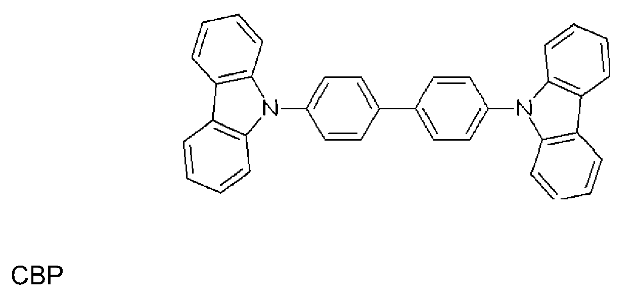
- The emissive layer may be formed with a host material in which the light emitting material as above described resides as a guest or the emissive layer may consist essentially of the light emitting material as above described itself. In the former case, the host material may be a hole-transporting material selected from the group of substituted tri-aryl amines. Preferably, the emissive layer is formed with a host material in which the light emitting material resides as a guest. The host material may be an electron-transporting material selected from the group of metal quinoxolates (e.g. aluminium quinolate (Alq3), lithium quinolate (Liq)), oxadiazoles and triazoles. An example of a host material is 4,4'-N,N'-dicarbazole-biphenyl ["CBP"], which has the formula :
-
- Optionally, the emissive layer may also contain a polarization molecule, present as a dopant in said host material and having a dipole moment, that generally affects the wavelength of light emitted when said light emitting material as above described, used as dopant, luminesces.
- A layer formed of an electron transporting material is advantageously used to transport electrons into the emissive layer comprising the light emitting material and the (optional) host material. The electron transporting material may be an electron-transporting matrix selected from the group of metal quinoxolates (e.g. Alq3, Liq), oxadiazoles and triazoles. An example of an electron transporting material is tris-(8-hydroxyquinoline)aluminum of formula ["Alq3"] :

- A layer formed of a hole transporting material is advantageously used to transport holes into the emissive layer comprising the light emitting material as above described and the (optional) host material. An example of a hole transporting material is 4,4'-bis[N-(1-naphthyl)-N-phenylamino] biphenyl ["α-NPD"].

- The use of an exciton blocking layer ("barrier layer") to confine excitons within the luminescent layer ("luminescent zone") is greatly preferred. For a hole-transporting host, the blocking layer may be placed between the emissive layer and the electron transport layer. An example of a material for such a barrier layer is 2,9-dimethyl-4,7-diphenyl-1,10-phenanthroline (also called bathocuproine or "BCP"), which has the formula

- The OLED has preferably a multilayer structure, as depicted in Figure 1, wherein 1 is a glass substrate, 2 is an ITO layer, 3 is a HTL layer comprising α-NPD, 4 is an EML comprising CBP as host material and the light emitting material as above defined as dopant in an amount of about 8 % wt with respect to the total weight of host plus dopant; 5 is a HBL comprising BCP; 6 is an ETL comprising Alq3; 7 is an Al layer cathode.
- Examples
- Synthesis of the 1-methyl-2-phenyl-imidazole
-

- Synthesis of [(1-methyl-2-phenyl-imidazole) 2 IrC|] 2 complex [complex (VI II)]

- Synthesis of [(1-methyl-2-phenyl-imidazole) 2 Ir(acac)] complex [complex ( III )]
- 271 mg (0.25 mmol) of complex (VIII) were dissolved in 50 ml of dichloromethane under inert atmosphere. Separately, 100 mg (1.00 mmol) of acetylacetone were mixed in 1 ml of ethanol with 400 mg (0.5 mmol) of tetrabutylammonium hydroxide [(C4H9)4NOH·30 H2O].
The so obtained solutions were mixed and heated at reflux during 4 hours. Complex (III) was isolated as a yellow pale green air-stable complex. 250 mg of solid were obtained (yield: 82 %), which were characterized by 1H-NMR in CH2Cl2.
1H-NMR (CDCl3, 298 K, 200 MHz, δ ppm) δ 1.79 (s, 6H of acetyl acetonate CH3), 4.1 (s, 6H of imidazole CH3), 5.16 (s, 1H of acetyl acetonate CH), 6.4 (dd, J = 7.46 and 1 Hz, 2H), 6.65 (dt, J = 7.26 and 1 Hz, 2H), 6.69 (dt, J = 7.3 and 1.3 Hz, 2H), 6.90 (d, J = 1.46 Hz, 2H), 7.00 (d, J = 1.49 Hz, 2H), and 7.38 (dd, J = 7.55 and 1.46 Hz, 2H). - Figure 2 shows the 1H-NMR spectrum of the complex (III) measured in CDCl3 at 298°C, which was found to be consistent with the proposed structure; the abscissa stands for δ in ppm.
- Figure 3 shows the absorption spectra registered from a complex (III) solution in dichloromethane at 273 K by excitation at 380 nm; the abscissa stands for the wavelength in nm and the ordinate stands for absorbance (OD).
- Figure 4 shows the emission spectra registered from a complex (III) solution in dichloromethane at 273 K by excitation at 380 nm; the abscissa stands for the wavelength in nm and the ordinate stands for emission intensity (cps).
Claims (6)
- A light emitting material comprising a neutral complex of formula (I) :

- The light emitting material of claim 1, said material comprising a neutral complex of formula (II) :

- The light emitting material of claim 2, said material comprising a neutral complex of formula (III):

- Use of the light emitting material according to anyone of claims 1 to 3 in the emitting layer of an organic light emitting device.
- Use of the light emitting material according to anyone of claims 1 to 3 as dopant in a host layer, functioning as an emissive layer in an organic light emitting device.
- An organic light emitting device (OLED) comprising an emissive layer (EML), said emissive layer comprising the light emitting material according to anyone of claims 1 to 3, optionally with a host material.
Priority Applications (5)
| Application Number | Priority Date | Filing Date | Title |
|---|---|---|---|
| EP06122205A EP1918349A1 (en) | 2006-10-12 | 2006-10-12 | Light-emitting material |
| PCT/EP2007/060836 WO2008043815A1 (en) | 2006-10-12 | 2007-10-11 | Light-emitting material |
| EP07821203A EP2076580A1 (en) | 2006-10-12 | 2007-10-11 | Light-emitting material |
| US12/444,793 US8518557B2 (en) | 2006-10-12 | 2007-10-11 | Light emitting materials comprising novel ortho-metalated transition metal complexes |
| JP2009531848A JP2010505915A (en) | 2006-10-12 | 2007-10-11 | Luminescent substance |
Applications Claiming Priority (1)
| Application Number | Priority Date | Filing Date | Title |
|---|---|---|---|
| EP06122205A EP1918349A1 (en) | 2006-10-12 | 2006-10-12 | Light-emitting material |
Publications (1)
| Publication Number | Publication Date |
|---|---|
| EP1918349A1 true EP1918349A1 (en) | 2008-05-07 |
Family
ID=37831489
Family Applications (2)
| Application Number | Title | Priority Date | Filing Date |
|---|---|---|---|
| EP06122205A Withdrawn EP1918349A1 (en) | 2006-10-12 | 2006-10-12 | Light-emitting material |
| EP07821203A Withdrawn EP2076580A1 (en) | 2006-10-12 | 2007-10-11 | Light-emitting material |
Family Applications After (1)
| Application Number | Title | Priority Date | Filing Date |
|---|---|---|---|
| EP07821203A Withdrawn EP2076580A1 (en) | 2006-10-12 | 2007-10-11 | Light-emitting material |
Country Status (4)
| Country | Link |
|---|---|
| US (1) | US8518557B2 (en) |
| EP (2) | EP1918349A1 (en) |
| JP (1) | JP2010505915A (en) |
| WO (1) | WO2008043815A1 (en) |
Families Citing this family (6)
| Publication number | Priority date | Publication date | Assignee | Title |
|---|---|---|---|---|
| EP1842854A1 (en) | 2006-04-07 | 2007-10-10 | SOLVAY (Société Anonyme) | Light-emitting material |
| TW200911821A (en) | 2007-06-08 | 2009-03-16 | Solvay | Light emitting material |
| TWI412528B (en) | 2007-06-08 | 2013-10-21 | Solvay | Light-emitting material |
| CN102317405A (en) * | 2008-07-16 | 2012-01-11 | 索尔维公司 | Light-emitting material comprising multinuclear complexes |
| EP2393820A4 (en) | 2009-02-06 | 2013-03-13 | Solvay | Phosphorescent light-emitting iridium complex containing pyridyltriazole ligand |
| GB2530748A (en) * | 2014-09-30 | 2016-04-06 | Cambridge Display Tech Ltd | Organic Light Emitting Device |
Citations (2)
| Publication number | Priority date | Publication date | Assignee | Title |
|---|---|---|---|---|
| US6687266B1 (en) * | 2002-11-08 | 2004-02-03 | Universal Display Corporation | Organic light emitting materials and devices |
| EP1486552A1 (en) * | 2003-06-12 | 2004-12-15 | Sony Corporation | Organic electroluminescent material, organic electroluminescent device, and heterocycle-containing iridium complex compound |
Family Cites Families (14)
| Publication number | Priority date | Publication date | Assignee | Title |
|---|---|---|---|---|
| US6670645B2 (en) * | 2000-06-30 | 2003-12-30 | E. I. Du Pont De Nemours And Company | Electroluminescent iridium compounds with fluorinated phenylpyridines, phenylpyrimidines, and phenylquinolines and devices made with such compounds |
| JP3991728B2 (en) | 2001-07-31 | 2007-10-17 | 三菱マテリアル株式会社 | Method for producing fluorine-substituted iridium complex |
| JP3991727B2 (en) | 2001-07-31 | 2007-10-17 | 三菱マテリアル株式会社 | Fluorine-substituted iridium complex, intermediate thereof and method for producing the same |
| JP5135660B2 (en) | 2001-09-27 | 2013-02-06 | コニカミノルタホールディングス株式会社 | Organic electroluminescence device |
| JP2004200141A (en) * | 2002-10-24 | 2004-07-15 | Toyota Industries Corp | Organic EL device |
| FR2846786B1 (en) * | 2002-11-05 | 2005-06-17 | PROCESS FOR QUICK THERMAL RECOVERY OF CROWN WAFERS | |
| DE10314102A1 (en) * | 2003-03-27 | 2004-10-14 | Covion Organic Semiconductors Gmbh | Process for the production of high-purity organo-iridium compounds |
| CN1829724B (en) * | 2003-07-22 | 2012-10-10 | 出光兴产株式会社 | Metal complex compound and organic electroluminescent element using the same |
| JP4337475B2 (en) | 2003-08-27 | 2009-09-30 | 三菱化学株式会社 | Organometallic complex, luminescent material, and organic electroluminescent device |
| US7393599B2 (en) * | 2004-05-18 | 2008-07-01 | The University Of Southern California | Luminescent compounds with carbene ligands |
| US20060008670A1 (en) * | 2004-07-06 | 2006-01-12 | Chun Lin | Organic light emitting materials and devices |
| EP2178348B1 (en) | 2004-07-23 | 2012-11-21 | Konica Minolta Holdings, Inc. | Organic electroluminescent element, display and illuminator |
| GB2476003B (en) * | 2005-06-09 | 2011-09-14 | Konica Minolta Holdings Inc | Organic electroluminescent element, illuminator and display |
| EP1936714A1 (en) | 2005-10-11 | 2008-06-25 | Konica Minolta Holdings, Inc. | Organic electroluminescent device, liquid crystal display and illuminating device |
-
2006
- 2006-10-12 EP EP06122205A patent/EP1918349A1/en not_active Withdrawn
-
2007
- 2007-10-11 EP EP07821203A patent/EP2076580A1/en not_active Withdrawn
- 2007-10-11 US US12/444,793 patent/US8518557B2/en not_active Expired - Fee Related
- 2007-10-11 JP JP2009531848A patent/JP2010505915A/en active Pending
- 2007-10-11 WO PCT/EP2007/060836 patent/WO2008043815A1/en not_active Ceased
Patent Citations (2)
| Publication number | Priority date | Publication date | Assignee | Title |
|---|---|---|---|---|
| US6687266B1 (en) * | 2002-11-08 | 2004-02-03 | Universal Display Corporation | Organic light emitting materials and devices |
| EP1486552A1 (en) * | 2003-06-12 | 2004-12-15 | Sony Corporation | Organic electroluminescent material, organic electroluminescent device, and heterocycle-containing iridium complex compound |
Also Published As
| Publication number | Publication date |
|---|---|
| US8518557B2 (en) | 2013-08-27 |
| JP2010505915A (en) | 2010-02-25 |
| EP2076580A1 (en) | 2009-07-08 |
| WO2008043815A1 (en) | 2008-04-17 |
| US20100102711A1 (en) | 2010-04-29 |
Similar Documents
| Publication | Publication Date | Title |
|---|---|---|
| KR101979179B1 (en) | Pyridyl carbene phosphorescent emitters | |
| KR102637435B1 (en) | Organic electroluminescent materials and devices | |
| JP2020114859A (en) | Phosphorescent material | |
| EP2007780B1 (en) | Light-emitting material | |
| JP5153161B2 (en) | Organometallic complex and organic EL device using the same | |
| US11765971B2 (en) | Luminescent tetradentate gold(III) compounds for organic light-emitting devices and their preparation | |
| KR20140052501A (en) | Method for mnufacturing of blue phosphorescence composition and organic light emittin diode comprising the same | |
| KR101863375B1 (en) | Ion-pairing soft salts based on organometallic complexes and their applications in organic light emitting diodes | |
| US8518557B2 (en) | Light emitting materials comprising novel ortho-metalated transition metal complexes | |
| US8357800B2 (en) | Bipyridine metal complexes for use as light-emitting material | |
| KR20080066672A (en) | Light emitting material | |
| KR20190127584A (en) | Organic electroluminescent materials and devices | |
| KR20200130669A (en) | Heteroleptic osmium complex and method of making the same | |
| KR20110099243A (en) | Phosphorescent material | |
| US8357799B2 (en) | Light emitting material | |
| EP1772507A1 (en) | Light-emitting material | |
| Dahule et al. | Optical Properties of Iridium Organic Complexes in Different Solvents | |
| HK1147760A (en) | Bipyridine metal complexes for use as light-emitting material |
Legal Events
| Date | Code | Title | Description |
|---|---|---|---|
| PUAI | Public reference made under article 153(3) epc to a published international application that has entered the european phase |
Free format text: ORIGINAL CODE: 0009012 |
|
| AK | Designated contracting states |
Kind code of ref document: A1 Designated state(s): AT BE BG CH CY CZ DE DK EE ES FI FR GB GR HU IE IS IT LI LT LU LV MC NL PL PT RO SE SI SK TR |
|
| AX | Request for extension of the european patent |
Extension state: AL BA HR MK RS |
|
| AKX | Designation fees paid | ||
| REG | Reference to a national code |
Ref country code: DE Ref legal event code: 8566 |
|
| STAA | Information on the status of an ep patent application or granted ep patent |
Free format text: STATUS: THE APPLICATION IS DEEMED TO BE WITHDRAWN |
|
| 18D | Application deemed to be withdrawn |
Effective date: 20081110 |