EP1918006A1 - Combination filter for a lubrication system - Google Patents
Combination filter for a lubrication system Download PDFInfo
- Publication number
- EP1918006A1 EP1918006A1 EP07119684A EP07119684A EP1918006A1 EP 1918006 A1 EP1918006 A1 EP 1918006A1 EP 07119684 A EP07119684 A EP 07119684A EP 07119684 A EP07119684 A EP 07119684A EP 1918006 A1 EP1918006 A1 EP 1918006A1
- Authority
- EP
- European Patent Office
- Prior art keywords
- filter
- bowl
- combination
- housing
- outlet port
- Prior art date
- Legal status (The legal status is an assumption and is not a legal conclusion. Google has not performed a legal analysis and makes no representation as to the accuracy of the status listed.)
- Withdrawn
Links
- 238000005461 lubrication Methods 0.000 title claims description 52
- 239000012530 fluid Substances 0.000 claims abstract description 65
- 238000004891 communication Methods 0.000 claims abstract description 14
- 238000001914 filtration Methods 0.000 claims abstract description 14
- 239000000463 material Substances 0.000 claims description 6
- 230000004888 barrier function Effects 0.000 claims description 5
- 239000011148 porous material Substances 0.000 claims description 4
- 230000008878 coupling Effects 0.000 description 16
- 238000010168 coupling process Methods 0.000 description 16
- 238000005859 coupling reaction Methods 0.000 description 16
- 238000004519 manufacturing process Methods 0.000 description 2
- 229910052751 metal Inorganic materials 0.000 description 2
- 239000002184 metal Substances 0.000 description 2
- 238000000034 method Methods 0.000 description 2
- 241001481828 Glyptocephalus cynoglossus Species 0.000 description 1
- 229910052782 aluminium Inorganic materials 0.000 description 1
- XAGFODPZIPBFFR-UHFFFAOYSA-N aluminium Chemical compound [Al] XAGFODPZIPBFFR-UHFFFAOYSA-N 0.000 description 1
- 230000006866 deterioration Effects 0.000 description 1
- 239000000835 fiber Substances 0.000 description 1
- 239000010419 fine particle Substances 0.000 description 1
- 238000009434 installation Methods 0.000 description 1
- 238000002955 isolation Methods 0.000 description 1
- 238000012423 maintenance Methods 0.000 description 1
- 239000011236 particulate material Substances 0.000 description 1
Images

Classifications
-
- B—PERFORMING OPERATIONS; TRANSPORTING
- B01—PHYSICAL OR CHEMICAL PROCESSES OR APPARATUS IN GENERAL
- B01D—SEPARATION
- B01D35/00—Filtering devices having features not specifically covered by groups B01D24/00 - B01D33/00, or for applications not specifically covered by groups B01D24/00 - B01D33/00; Auxiliary devices for filtration; Filter housing constructions
- B01D35/30—Filter housing constructions
- B01D35/301—Constructions of two or more housings
-
- B—PERFORMING OPERATIONS; TRANSPORTING
- B01—PHYSICAL OR CHEMICAL PROCESSES OR APPARATUS IN GENERAL
- B01D—SEPARATION
- B01D29/00—Filters with filtering elements stationary during filtration, e.g. pressure or suction filters, not covered by groups B01D24/00 - B01D27/00; Filtering elements therefor
- B01D29/11—Filters with filtering elements stationary during filtration, e.g. pressure or suction filters, not covered by groups B01D24/00 - B01D27/00; Filtering elements therefor with bag, cage, hose, tube, sleeve or like filtering elements
- B01D29/114—Filters with filtering elements stationary during filtration, e.g. pressure or suction filters, not covered by groups B01D24/00 - B01D27/00; Filtering elements therefor with bag, cage, hose, tube, sleeve or like filtering elements arranged for inward flow filtration
-
- B—PERFORMING OPERATIONS; TRANSPORTING
- B01—PHYSICAL OR CHEMICAL PROCESSES OR APPARATUS IN GENERAL
- B01D—SEPARATION
- B01D29/00—Filters with filtering elements stationary during filtration, e.g. pressure or suction filters, not covered by groups B01D24/00 - B01D27/00; Filtering elements therefor
- B01D29/11—Filters with filtering elements stationary during filtration, e.g. pressure or suction filters, not covered by groups B01D24/00 - B01D27/00; Filtering elements therefor with bag, cage, hose, tube, sleeve or like filtering elements
- B01D29/117—Filters with filtering elements stationary during filtration, e.g. pressure or suction filters, not covered by groups B01D24/00 - B01D27/00; Filtering elements therefor with bag, cage, hose, tube, sleeve or like filtering elements arranged for outward flow filtration
-
- B—PERFORMING OPERATIONS; TRANSPORTING
- B01—PHYSICAL OR CHEMICAL PROCESSES OR APPARATUS IN GENERAL
- B01D—SEPARATION
- B01D29/00—Filters with filtering elements stationary during filtration, e.g. pressure or suction filters, not covered by groups B01D24/00 - B01D27/00; Filtering elements therefor
- B01D29/50—Filters with filtering elements stationary during filtration, e.g. pressure or suction filters, not covered by groups B01D24/00 - B01D27/00; Filtering elements therefor with multiple filtering elements, characterised by their mutual disposition
-
- B—PERFORMING OPERATIONS; TRANSPORTING
- B01—PHYSICAL OR CHEMICAL PROCESSES OR APPARATUS IN GENERAL
- B01D—SEPARATION
- B01D46/00—Filters or filtering processes specially modified for separating dispersed particles from gases or vapours
- B01D46/0002—Casings; Housings; Frame constructions
- B01D46/0005—Mounting of filtering elements within casings, housings or frames
- B01D46/0008—Two or more filter elements not fluidly connected positioned in the same housing
Definitions
- the present invention generally relates to a filter for a lubrication system, and more particularly relates to a combination filter for a lubrication system having a coarse filter and a fine filter.
- Lubrication systems for aircraft engines such as an auxiliary power unit (APU) generally include a coarse screen filter in an oil scavenge passage between a gearbox mounted generator and a lubrication pump.
- a second, fine screen filter is included between the lubrication pump and the components to be lubricated in the gearbox.
- the coarse screen filter is intended to collect relatively large pieces of debris that can result from generator wear or failure. If the relatively large pieces of debris are allowed to reach the lubrication pump, significant damage to the rotating pump elements can occur. This can result in a failure of the APU.
- the APU should be able to continue to operate after a generator failure, and if the pump elements continue to pump, the APU typically can continue to operate after a generator failure.
- the coarse screen filter is typically a small screen such as a witches hat installed directly in the oil passage. This configuration typically requires an access point in the oil passage to allow for filter installation and removal. Moreover, because the screens are relatively small, they can plug up quickly. If the coarse screen filter plugs, the resulting backpressure can lead to further undesirable consequences.
- the combination filter includes a filter housing having first and second inlet ports and first and second outlet ports; a first filter bowl coupled to the housing, the first filter bowl having at least an inner surface and an outer surface, the first filter bowl inner surface defining a first cavity that is in fluid communication with the first inlet port and the first outlet port; a second filter bowl coupled to the housing and at least partially disposed within the first cavity of the first filter bowl, the second filter bowl having at least an inner surface and an outer surface, the second filter bowl inner surface defining a second cavity that is in fluid communication with the second inlet port and the second outlet port, the second filter bowl outer surface defining a barrier that fluidly isolates the first inlet port and the first outlet port from the second inlet port and the second outlet port; a first filter disposed within the first filter bowl for filtering fluid that flows between the first inlet port and the first outlet port; and a second filter disposed within the second filter bowl for filtering fluid that flows between the second inlet port and the second outlet port.
- a lubrication system for an auxiliary power unit includes a clutch, an engine, a lubrication fluid sump for receiving scavenged lubrication fluid from components in the clutch and engine, a generator, a lubrication fluid pump, and a combination filter.
- the combination filter includes a filter housing having first and second inlet ports and first and second outlet ports; a first filter bowl coupled to the housing, the first filter bowl having at least an inner surface and an outer surface, the first filter bowl inner surface defining a first cavity that is in fluid communication with the first inlet port and the first outlet port; a second filter bowl coupled to the housing and at least partially disposed within the first cavity of the first filter bowl, the second filter bowl having at least an inner surface and an outer surface, the second filter bowl inner surface defining a second cavity that is in fluid communication with the second inlet port and the second outlet port, the second filter bowl outer surface defining a barrier that fluidly isolates the first inlet port and the first outlet port from the second inlet port and the second outlet port; a first filter disposed within the first filter bowl for filtering fluid that flows between the first inlet port and the first outlet port; and a second filter disposed within the second filter bowl for filtering fluid that flows between the second inlet port and the second outlet port.
- a method of manufacturing a combination filter includes providing a filter housing having first and second inlet ports and first and second outlet ports; coupling a first filter bowl to the housing, the first filter bowl having at least an inner surface and an outer surface, the first filter bowl inner surface defining a first cavity that is in fluid communication with the first inlet port and the first outlet port; coupling a second filter bowl to the housing and at least partially disposed within the first cavity of the first filter bowl, the second filter bowl having at least an inner surface and an outer surface, the second filter bowl inner surface defining a second cavity that is in fluid communication with the second inlet port and the second outlet port, the second filter bowl outer surface defining a barrier that fluidly isolates the first inlet port and the first outlet port from the second inlet port and the second outlet port; providing a first filter within the first filter bowl for filtering fluid that flows between the first inlet port and the first outlet port; and providing a second filter within the second filter bowl for filtering fluid that flows between the second inlet port and the second outlet port.
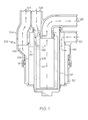
- FIG. 1 is a cross sectional view of an exemplary embodiment of the combination filter of the present invention.
- FIG. 2 is a schematic view of a lubrication system including the combination filter shown in FIG. 1.
- an exemplary embodiment of the combination filter 102 includes a housing 104, a first filter 106, and a second filter 108.
- the housing 104 includes a first inlet port 122, a second inlet port 126, a first outlet port 124, and a second outlet port 128.
- the housing 104 is selectively attachable to the first filter 106 and the second filter 108 at coupling 114 and coupling 116, respectively.
- the first filter 106 is a coarse filter and the second filter 108 is a fine filter.
- the central longitudinal axis of both the first filter 106 and the second filter 108 can correspond to a center axis 150 of the combination filter 102. In other words, the first and second filters 106, 108 can be generally centered within the combination filter 102.
- a first filter bowl 110 is selectively attachable to the housing 104 at coupling 118.
- the first filter bowl 110 defines a cavity for enclosing the first filter 106.
- the cavity of the first filter bowl 110 is in fluid communication with the first inlet port 122 and the first outlet port 124.
- a second filter bowl 112 is selectively attachable to the housing 104.
- the second filter bowl 112 can be attached to the first filter bowl 110 to couple the second filter bowl 112 to the housing 104 at seal 120.
- the second filter bowl 112 includes an inner surface defining a cavity to enclose the second filter 108.
- the cavity of the second filter bowl 112 is in fluid communication with the second inlet port 126 and the second outlet port 128.
- the second filter bowl 112 further includes an outer surface that defines a barrier that fluidly isolates the first inlet port 122 and the first outlet port 124 from the second inlet port 126 and the second outlet port 128 to thus maintain a fluid isolation between the first filter 106 and the second filter 108.
- the first and second filter bowls 110, 112 can be machined into one piece to define two cavities and to respectively fluidly isolate the first filter 106 and the second filter 108. Generally, debris filtered by the first filter 106 remains in the first filter 106 or the first filter bowl 110, and debris filtered by the second filter 108 remains in the second filter 108 or the second filter bowl 112.
- the first and second filters 106, 108 can be cylindrically shaped, and the first filter 106 can surround the second filter 108. Other shapes of the first and second filters 106, 108 and the first and second filter bowls 110, 112 are possible. Similarly, the first filter bowl 110 and the second filter bowl 112 are cylindrically shaped, and the first filter bowl 110 can at least partially surround the second filter bowl 112. Other shapes of the first and second filters 106, 108 and the first and second filter bowls 110, 112 are possible.
- the diameter of the second filter 108 can be slightly larger than the diameter of the second outlet port 128.
- the first and second filters 106, 108 can be replaced or cleaned by uncoupling the filters 106, 108 at couplings 114, 116.
- the first and second filters 106, 108 are generally self-supporting, although support structures can accompany a filtering material that makes up the first and second filters 106, 108.
- Coupling 114 can be a notch in the housing 104 that maintains the position of the first filter 106.
- Coupling 116 can be an O-ring seal that forms a friction fit between the second filter 108 and the housing 104.
- the coupling 118 between the first filter bowl 110 and the housing 104 is an O-ring seal and additionally includes threaded portions to screw the first filter bowl 110 to the housing 104.
- the coupling 118 can be on the interior surface of the housing 104 facing the central axis 150 of the combination filter 102 and on the exterior surface of the first filter bowl filter 110 facing away from the central axis 150 of the combination filter 102.
- the first filter bowl 110 can extend beyond the coupling 118 such that the first filter bowl 110 and the housing 104 overlap.
- the coupling 120 between the second filter bowl 112 and the housing 104 can be on a surface of the second filter bowl 112 facing away from the central axis 150 of the combination filter 102 and on a surface of the housing 104 facing the central axis 150 of the combination filter 102.
- the coupling 120 can be an O-ring seal that extends circumferentially from adjacent the second inlet port 126 to a portion of the housing 104 between the first inlet port 122 and the second outlet port 128.
- the second filter bowl 112 can be additionally supported by its connection with the first filter bowl 110.
- the coupling 116 between the second filter 108 and the housing 104 can be on a surface of the housing 104 facing away from the central axis 150 of the combination filter 102 and on a surface of the second filter 108 facing the central axis 150 of the combination filter 102.
- the coupling 116 generally circumscribes the second outlet port 128 with at least a portion of the coupling 116 adjacent the second inlet port 126.
- the first inlet port 122 is generally perpendicular to the central axis 150 of the combination filter 102
- the first outlet port 124 is generally parallel to the central axis 150 of the combination filter 102
- the second inlet port 126 can be generally parallel to the central axis 150 of the combination filter 102
- the second outlet port 128 can extend parallel to the central axis 150 of the combination filter 102 and then bend 90° to be perpendicular to the central axis 150.
- combination filter 102 includes the operation of the combination filter 102 within a lubrication system 100 is described with reference to FIG. 1 and additionally with reference to FIG. 2.
- the lubrication system 100 includes a lubrication fluid sump 130 that scavenges lubrication fluid from a gearbox 154 and an engine 140.
- the lubrication fluid sump 130 includes a conduit that is coupled to a lubrication fluid pump 134.
- the lubrication fluid pump 124 pumps the lubrication fluid to a generator 152 and the engine 140.
- the lubrication fluid that flows through the generator 152 then flows to the first inlet port 122 in the housing 104 of the combination filter 102.
- the first inlet port 122 is in fluid communication with the first filter 106, and the first filter 106 filters the lubrication fluid from the generator 152.
- the lubrication fluid is passed outwardly through the first filter 106.
- the lubrication fluid from the generator 152 can contain relatively large pieces of debris that are filtered out by the first filter 106.
- the lubrication fluid that has undergone initial filtration flows circumferentially between the first filter 106 and the first filter bowl 110 to the first outlet port 124 in the housing 104.
- the housing 104 can define an annular passage 148 to accommodate the lubrication fluid passing through the first filter 108 and transitioning to the first outlet port 124.
- the lubrication fluid flows out of the first outlet port 124 to a lube pump inlet conduit and subsequently to the lubrication fluid pump 134.
- the lubrication fluid flows through the lubrication fluid pump 134 and back to the combination filter 102.
- the lubrication fluid enters the combination filter 102 from the lubrication fluid pump 134 at the second inlet port 126 in the housing 104.
- the second inlet port 126 is in fluid communication with the second filter 108.
- the lubrication fluid is filtered by the second filter 108 to filter out relatively fine particles of debris.
- the lubrication fluid is passed inwardly through the second filter 108.
- the lubrication fluid then flows circumferentially between the second filter bowl 112 and the second filter 108 to a second outlet port 128 in the housing 104.
- the lubrication fluid exits the combination filter 102 via the second outlet port 128.
- the lubrication fluid then flows to a clutch in the gearbox 154.
- the lubrication fluid which is now at its cleanest after being filtered by the first filter 106 and the second filter 108, lubricates the components within the clutch in the gearbox 154.
- the lubrication fluid flows back to the lubrication fluid sump 130, which completes the circuit of the lubrication system 100.
- the first filter 106 can include a wire mesh or metal screen.
- the first filter 106 can be a metal tube, for example aluminum, with laser drilled holes.
- the second filter 108 is preferably a corrugated, mesh, fiber or paper filter and adapted to provide removal of fine particulate material that could prove harmful to the clutch in the gearbox 154.
- the pore size of the first filter 106 can be about 700 to 1000 microns, and the pore size of the second filter can be 3 to 5 microns.
- the position of second filter 108 on the downstream side of the lubrication fluid pump 134 also serves to capture materials that may enter the system due to deterioration of components of the lubrication fluid pump 134. As a result, potential damage to downstream system components is minimized.
- the combination filter 102 prevents the second filter 108 from being clogged with relatively large pieces of debris and prolongs the life of the second filter 108 and prevents debris from damaging the lubrication fluid pump 134. Furthermore, since the first filter 106 surrounds the second filter 108, a relatively larger filter surface area can be provided. Moreover, the first filter 106 can be easier to remove and clean than the second filter 108.
- both the first filter 106 and the second filter 108 are packaged into the same filter housing 104 and within the larger, first filter bowl 110. This results in lower machine and fabrication costs, maintenance, and weight. Moreover, the first filter 106 has a larger filtering surface area as compared to conventional filters because of the cylindrical shape, as well as having the first filter 106 located outside of the smaller, second filter 108.
- the combination filter 102 can further include a bracket (not shown) for mounting the combination filter 102 in an engine, for example, an auxiliary power unit (APU). Alternately, the combination filter 102 can be combined integrally with the gearbox 154 or the lubrication fluid pump 134.
- a bracket for mounting the combination filter 102 in an engine, for example, an auxiliary power unit (APU). Alternately, the combination filter 102 can be combined integrally with the gearbox 154 or the lubrication fluid pump 134.
- the lubrication fluid can flow in opposite directions as that shown in FIG. 1.
- the lubrication fluid can flow into the combination filter 102 at port 124, flow inwardly through the first filter 106, and exit the combination filter 102 at port 122.
- the lubrication fluid can flow into the combination filter 102 at port 128, flow outwardly through the second filter 108, and exit the combination filter 102 at port 126.
- the positions of the first and second filters 106, 108 can be reversed.
Landscapes
- Chemical & Material Sciences (AREA)
- Chemical Kinetics & Catalysis (AREA)
- Lubrication Details And Ventilation Of Internal Combustion Engines (AREA)
- General Details Of Gearings (AREA)
Abstract
Description
- The present invention generally relates to a filter for a lubrication system, and more particularly relates to a combination filter for a lubrication system having a coarse filter and a fine filter.
- Lubrication systems for aircraft engines such as an auxiliary power unit (APU) generally include a coarse screen filter in an oil scavenge passage between a gearbox mounted generator and a lubrication pump. A second, fine screen filter is included between the lubrication pump and the components to be lubricated in the gearbox. The coarse screen filter is intended to collect relatively large pieces of debris that can result from generator wear or failure. If the relatively large pieces of debris are allowed to reach the lubrication pump, significant damage to the rotating pump elements can occur. This can result in a failure of the APU. Generally, the APU should be able to continue to operate after a generator failure, and if the pump elements continue to pump, the APU typically can continue to operate after a generator failure. Moreover, the coarse screen filter is typically a small screen such as a witches hat installed directly in the oil passage. This configuration typically requires an access point in the oil passage to allow for filter installation and removal. Moreover, because the screens are relatively small, they can plug up quickly. If the coarse screen filter plugs, the resulting backpressure can lead to further undesirable consequences.
- One method that has been proposed for reducing backpressure is to increase the coarse screen filter flow area. This solution, however, exhibits its own drawbacks. For example, increasing the surface area of the coarse screen filter may require a larger filter in a separate housing. This solution may add cost, weight, complexity, and spatial volume to the gearbox.
- Accordingly, it is desirable to increase the surface area of the coarse screen filter without adding significant weight, costs, complexities, or spatial volume to the gearbox. Furthermore, other desirable features and characteristics of the present invention will become apparent from the subsequent detailed description of the invention and the appended claims, taken in conjunction with the accompanying drawings and this background of the invention.
- A combination filter is provided. The combination filter includes a filter housing having first and second inlet ports and first and second outlet ports; a first filter bowl coupled to the housing, the first filter bowl having at least an inner surface and an outer surface, the first filter bowl inner surface defining a first cavity that is in fluid communication with the first inlet port and the first outlet port; a second filter bowl coupled to the housing and at least partially disposed within the first cavity of the first filter bowl, the second filter bowl having at least an inner surface and an outer surface, the second filter bowl inner surface defining a second cavity that is in fluid communication with the second inlet port and the second outlet port, the second filter bowl outer surface defining a barrier that fluidly isolates the first inlet port and the first outlet port from the second inlet port and the second outlet port; a first filter disposed within the first filter bowl for filtering fluid that flows between the first inlet port and the first outlet port; and a second filter disposed within the second filter bowl for filtering fluid that flows between the second inlet port and the second outlet port.
- A lubrication system for an auxiliary power unit includes a clutch, an engine, a lubrication fluid sump for receiving scavenged lubrication fluid from components in the clutch and engine, a generator, a lubrication fluid pump, and a combination filter. The combination filter includes a filter housing having first and second inlet ports and first and second outlet ports; a first filter bowl coupled to the housing, the first filter bowl having at least an inner surface and an outer surface, the first filter bowl inner surface defining a first cavity that is in fluid communication with the first inlet port and the first outlet port; a second filter bowl coupled to the housing and at least partially disposed within the first cavity of the first filter bowl, the second filter bowl having at least an inner surface and an outer surface, the second filter bowl inner surface defining a second cavity that is in fluid communication with the second inlet port and the second outlet port, the second filter bowl outer surface defining a barrier that fluidly isolates the first inlet port and the first outlet port from the second inlet port and the second outlet port; a first filter disposed within the first filter bowl for filtering fluid that flows between the first inlet port and the first outlet port; and a second filter disposed within the second filter bowl for filtering fluid that flows between the second inlet port and the second outlet port.
- A method of manufacturing a combination filter is provided. The method includes providing a filter housing having first and second inlet ports and first and second outlet ports; coupling a first filter bowl to the housing, the first filter bowl having at least an inner surface and an outer surface, the first filter bowl inner surface defining a first cavity that is in fluid communication with the first inlet port and the first outlet port; coupling a second filter bowl to the housing and at least partially disposed within the first cavity of the first filter bowl, the second filter bowl having at least an inner surface and an outer surface, the second filter bowl inner surface defining a second cavity that is in fluid communication with the second inlet port and the second outlet port, the second filter bowl outer surface defining a barrier that fluidly isolates the first inlet port and the first outlet port from the second inlet port and the second outlet port; providing a first filter within the first filter bowl for filtering fluid that flows between the first inlet port and the first outlet port; and providing a second filter within the second filter bowl for filtering fluid that flows between the second inlet port and the second outlet port.
- The present invention will hereinafter be described in conjunction with the following drawing figures, wherein like numerals denote like elements, and
- FIG. 1 is a cross sectional view of an exemplary embodiment of the combination filter of the present invention; and
- FIG. 2 is a schematic view of a lubrication system including the combination filter shown in FIG. 1.
- The following detailed description of the invention is merely exemplary in nature and is not intended to limit the invention or the application and uses of the invention. Furthermore, there is no intention to be bound by any theory presented in the preceding background of the invention or the following detailed description of the invention.
- Referring to FIG. 1, an exemplary embodiment of the
combination filter 102 includes ahousing 104, afirst filter 106, and asecond filter 108. Thehousing 104 includes afirst inlet port 122, asecond inlet port 126, afirst outlet port 124, and asecond outlet port 128. Thehousing 104 is selectively attachable to thefirst filter 106 and thesecond filter 108 atcoupling 114 andcoupling 116, respectively. In one embodiment, thefirst filter 106 is a coarse filter and thesecond filter 108 is a fine filter. The central longitudinal axis of both thefirst filter 106 and thesecond filter 108 can correspond to a center axis 150 of thecombination filter 102. In other words, the first andsecond filters combination filter 102. - A
first filter bowl 110 is selectively attachable to thehousing 104 atcoupling 118. Thefirst filter bowl 110 defines a cavity for enclosing thefirst filter 106. The cavity of thefirst filter bowl 110 is in fluid communication with thefirst inlet port 122 and thefirst outlet port 124. Asecond filter bowl 112 is selectively attachable to thehousing 104. In one embodiment, thesecond filter bowl 112 can be attached to thefirst filter bowl 110 to couple thesecond filter bowl 112 to thehousing 104 at seal 120. Thesecond filter bowl 112 includes an inner surface defining a cavity to enclose thesecond filter 108. The cavity of thesecond filter bowl 112 is in fluid communication with thesecond inlet port 126 and thesecond outlet port 128. Thesecond filter bowl 112 further includes an outer surface that defines a barrier that fluidly isolates thefirst inlet port 122 and thefirst outlet port 124 from thesecond inlet port 126 and thesecond outlet port 128 to thus maintain a fluid isolation between thefirst filter 106 and thesecond filter 108. In an alternate embodiment, the first andsecond filter bowls first filter 106 and thesecond filter 108. Generally, debris filtered by thefirst filter 106 remains in thefirst filter 106 or thefirst filter bowl 110, and debris filtered by thesecond filter 108 remains in thesecond filter 108 or thesecond filter bowl 112. - The first and
second filters first filter 106 can surround thesecond filter 108. Other shapes of the first andsecond filters second filter bowls first filter bowl 110 and thesecond filter bowl 112 are cylindrically shaped, and thefirst filter bowl 110 can at least partially surround thesecond filter bowl 112. Other shapes of the first andsecond filters second filter bowls second filter 108 can be slightly larger than the diameter of thesecond outlet port 128. - The first and
second filters filters couplings second filters second filters Coupling 114 can be a notch in thehousing 104 that maintains the position of thefirst filter 106.Coupling 116 can be an O-ring seal that forms a friction fit between thesecond filter 108 and thehousing 104. In one embodiment, thecoupling 118 between thefirst filter bowl 110 and thehousing 104 is an O-ring seal and additionally includes threaded portions to screw thefirst filter bowl 110 to thehousing 104. Thecoupling 118 can be on the interior surface of thehousing 104 facing the central axis 150 of thecombination filter 102 and on the exterior surface of the firstfilter bowl filter 110 facing away from the central axis 150 of thecombination filter 102. Thefirst filter bowl 110 can extend beyond thecoupling 118 such that thefirst filter bowl 110 and thehousing 104 overlap. The coupling 120 between thesecond filter bowl 112 and thehousing 104 can be on a surface of thesecond filter bowl 112 facing away from the central axis 150 of thecombination filter 102 and on a surface of thehousing 104 facing the central axis 150 of thecombination filter 102. The coupling 120 can be an O-ring seal that extends circumferentially from adjacent thesecond inlet port 126 to a portion of thehousing 104 between thefirst inlet port 122 and thesecond outlet port 128. As noted above, thesecond filter bowl 112 can be additionally supported by its connection with thefirst filter bowl 110. Thecoupling 116 between thesecond filter 108 and thehousing 104 can be on a surface of thehousing 104 facing away from the central axis 150 of thecombination filter 102 and on a surface of thesecond filter 108 facing the central axis 150 of thecombination filter 102. Thecoupling 116 generally circumscribes thesecond outlet port 128 with at least a portion of thecoupling 116 adjacent thesecond inlet port 126. - In one embodiment, the
first inlet port 122 is generally perpendicular to the central axis 150 of thecombination filter 102, and thefirst outlet port 124 is generally parallel to the central axis 150 of thecombination filter 102. Thesecond inlet port 126 can be generally parallel to the central axis 150 of thecombination filter 102, and thesecond outlet port 128 can extend parallel to the central axis 150 of thecombination filter 102 and then bend 90° to be perpendicular to the central axis 150. - Further details of the
combination filter 102, including the operation of thecombination filter 102 within a lubrication system 100 is described with reference to FIG. 1 and additionally with reference to FIG. 2. - The lubrication system 100 includes a
lubrication fluid sump 130 that scavenges lubrication fluid from agearbox 154 and anengine 140. Thelubrication fluid sump 130 includes a conduit that is coupled to alubrication fluid pump 134. Thelubrication fluid pump 124 pumps the lubrication fluid to agenerator 152 and theengine 140. The lubrication fluid that flows through thegenerator 152 then flows to thefirst inlet port 122 in thehousing 104 of thecombination filter 102. Thefirst inlet port 122 is in fluid communication with thefirst filter 106, and thefirst filter 106 filters the lubrication fluid from thegenerator 152. As shown bypath 144 of FIG. 1, the lubrication fluid is passed outwardly through thefirst filter 106. The lubrication fluid from thegenerator 152 can contain relatively large pieces of debris that are filtered out by thefirst filter 106. - From the
first filter 106, the lubrication fluid that has undergone initial filtration flows circumferentially between thefirst filter 106 and thefirst filter bowl 110 to thefirst outlet port 124 in thehousing 104. Thehousing 104 can define anannular passage 148 to accommodate the lubrication fluid passing through thefirst filter 108 and transitioning to thefirst outlet port 124. The lubrication fluid flows out of thefirst outlet port 124 to a lube pump inlet conduit and subsequently to thelubrication fluid pump 134. - The lubrication fluid flows through the
lubrication fluid pump 134 and back to thecombination filter 102. The lubrication fluid enters thecombination filter 102 from thelubrication fluid pump 134 at thesecond inlet port 126 in thehousing 104. Thesecond inlet port 126 is in fluid communication with thesecond filter 108. The lubrication fluid is filtered by thesecond filter 108 to filter out relatively fine particles of debris. As shown bypath 146 of FIG. 1, the lubrication fluid is passed inwardly through thesecond filter 108. The lubrication fluid then flows circumferentially between thesecond filter bowl 112 and thesecond filter 108 to asecond outlet port 128 in thehousing 104. The lubrication fluid exits thecombination filter 102 via thesecond outlet port 128. - The lubrication fluid then flows to a clutch in the
gearbox 154. The lubrication fluid, which is now at its cleanest after being filtered by thefirst filter 106 and thesecond filter 108, lubricates the components within the clutch in thegearbox 154. Once the lubrication fluid has lubricated the components of the clutch in thegearbox 154, the lubrication fluid flows back to thelubrication fluid sump 130, which completes the circuit of the lubrication system 100. - The
first filter 106 can include a wire mesh or metal screen. Thefirst filter 106 can be a metal tube, for example aluminum, with laser drilled holes. Thesecond filter 108 is preferably a corrugated, mesh, fiber or paper filter and adapted to provide removal of fine particulate material that could prove harmful to the clutch in thegearbox 154. In one embodiment, the pore size of thefirst filter 106 can be about 700 to 1000 microns, and the pore size of the second filter can be 3 to 5 microns. The position ofsecond filter 108 on the downstream side of thelubrication fluid pump 134 also serves to capture materials that may enter the system due to deterioration of components of thelubrication fluid pump 134. As a result, potential damage to downstream system components is minimized. - By first filtering the lubrication fluid with the
first filter 106, thecombination filter 102 prevents thesecond filter 108 from being clogged with relatively large pieces of debris and prolongs the life of thesecond filter 108 and prevents debris from damaging thelubrication fluid pump 134. Furthermore, since thefirst filter 106 surrounds thesecond filter 108, a relatively larger filter surface area can be provided. Moreover, thefirst filter 106 can be easier to remove and clean than thesecond filter 108. - In one embodiment of the present invention, both the
first filter 106 and thesecond filter 108 are packaged into thesame filter housing 104 and within the larger,first filter bowl 110. This results in lower machine and fabrication costs, maintenance, and weight. Moreover, thefirst filter 106 has a larger filtering surface area as compared to conventional filters because of the cylindrical shape, as well as having thefirst filter 106 located outside of the smaller,second filter 108. - The
combination filter 102 can further include a bracket (not shown) for mounting thecombination filter 102 in an engine, for example, an auxiliary power unit (APU). Alternately, thecombination filter 102 can be combined integrally with thegearbox 154 or thelubrication fluid pump 134. - In alternate embodiments, the lubrication fluid can flow in opposite directions as that shown in FIG. 1. For example, the lubrication fluid can flow into the
combination filter 102 atport 124, flow inwardly through thefirst filter 106, and exit thecombination filter 102 atport 122. Similarly, the lubrication fluid can flow into thecombination filter 102 atport 128, flow outwardly through thesecond filter 108, and exit thecombination filter 102 atport 126. In another embodiment, the positions of the first andsecond filters - While at least one exemplary embodiment has been presented in the foregoing detailed description of the invention, it should be appreciated that a vast number of variations exist. It should also be appreciated that the exemplary embodiment or exemplary embodiments are only examples, and are not intended to limit the scope, applicability, or configuration of the invention in any way. Rather, the foregoing detailed description will provide those skilled in the art with a convenient road map for implementing an exemplary embodiment of the invention. It being understood that various changes may be made in the function and arrangement of elements described in an exemplary embodiment without departing from the scope of the invention as set forth in the appended claims.
Claims (10)
- A combination filter (102), comprising:a filter housing (104) having first and second inlet ports (122, 126) and first and second outlet ports (124, 128);a first filter bowl (110) coupled to the housing (104), the first filter bowl (110) having at least an inner surface and an outer surface, the first filter bowl inner surface defining a first cavity that is in fluid communication with the first inlet port and the first outlet port;a second filter bowl (112) coupled to the housing (104) and at least partially disposed within the first cavity of the first filter bowl (110), the second filter bowl (112) having at least an inner surface and an outer surface, the second filter bowl inner surface defining a second cavity that is in fluid communication with the second inlet port (126) and the second outlet port (128), the second filter bowl outer surface defining a barrier that fluidly isolates the first inlet port (122) and the first outlet port (124) from the second inlet port (126) and the second outlet port (128);a first filter (106) disposed within the first filter bowl (110) for filtering fluid that flows between the first inlet port (122) and the first outlet port (124); anda second filter (108) disposed within the second filter bowl (112) for filtering fluid that flows between the second inlet port (126) and the second outlet port (128).
- The combination filter (102) of claim 1, wherein the first and second filters (106, 108) are cylindrical
- The combination filter (102) of claim 2, wherein the first filter (106) surrounds the second filter (108).
- The combination filter (102) of claim 1, wherein the first filter (106) includes a coarse filter material and the second filter (108) includes a fine filter material.
- The combination filter (102) of claim 1, wherein the first and second filters (106, 108) are coupled to the housing (104).
- The combination filter (102) of claim 1, wherein the combination filter (102) includes a central longitudinal axis (150), the first inlet port (122) and the first outlet port (124) being configured such that the lubrication fluid flows outwardly through the first filter (106), away from the central longitudinal axis (150).
- The combination filter (102) of claim 1, wherein the combination filter (102) includes a central longitudinal axis (150), the second inlet port (126) and the second outlet port (128) being configured such that the lubrication fluid flows inwardly through the second filter (108), toward the central longitudinal axis (150).
- The combination filter (102) of claim 1, wherein the first filter (106) includes a filter material with a pore size of about 700 microns to about 1000 microns.
- The combination filter (102) of claim 1, wherein the second filter (108) includes a filter material with a pore size of about 3 microns to about 5 microns.
- The combination filter (102) of claim 1, wherein the first filter (106) and the second filter (108) are releasably attached to the housing (104).
Applications Claiming Priority (1)
| Application Number | Priority Date | Filing Date | Title |
|---|---|---|---|
| US11/590,358 US20080099388A1 (en) | 2006-10-31 | 2006-10-31 | Combination filter for a lubrication system |
Publications (1)
| Publication Number | Publication Date |
|---|---|
| EP1918006A1 true EP1918006A1 (en) | 2008-05-07 |
Family
ID=38983287
Family Applications (1)
| Application Number | Title | Priority Date | Filing Date |
|---|---|---|---|
| EP07119684A Withdrawn EP1918006A1 (en) | 2006-10-31 | 2007-10-30 | Combination filter for a lubrication system |
Country Status (2)
| Country | Link |
|---|---|
| US (1) | US20080099388A1 (en) |
| EP (1) | EP1918006A1 (en) |
Cited By (1)
| Publication number | Priority date | Publication date | Assignee | Title |
|---|---|---|---|---|
| WO2011057716A1 (en) * | 2009-11-10 | 2011-05-19 | Hydac Filtertechnik Gmbh | Filter |
Families Citing this family (3)
| Publication number | Priority date | Publication date | Assignee | Title |
|---|---|---|---|---|
| WO2012145372A2 (en) * | 2011-04-18 | 2012-10-26 | Cummins Filtration Ip, Inc. | Filter-in-filter with funnel shaped passageway |
| US9849411B2 (en) * | 2014-05-28 | 2017-12-26 | United Technologies Corporation | Scavenge filter system for a gas turbine engine |
| US12263432B2 (en) | 2021-12-17 | 2025-04-01 | Pratt & Whitney Canada Corp. | Filter assembly with sedimentation pocket |
Citations (4)
| Publication number | Priority date | Publication date | Assignee | Title |
|---|---|---|---|---|
| US5922199A (en) * | 1993-09-15 | 1999-07-13 | Parker Hannifin Corporation | Double pass fuel filter assembly |
| WO2003078821A2 (en) * | 2002-03-14 | 2003-09-25 | Delphi Technologies, Inc. | Fuel system |
| US20060191832A1 (en) * | 2005-02-14 | 2006-08-31 | Richie Bryant L | Dual media fuel filter and fuel/water separator cartridge filter system |
| WO2007110049A1 (en) * | 2006-03-20 | 2007-10-04 | Hengst Gmbh & Co. Kg | Filter insert having a closure for a second filter chamber |
Family Cites Families (15)
| Publication number | Priority date | Publication date | Assignee | Title |
|---|---|---|---|---|
| US2253636A (en) * | 1940-02-12 | 1941-08-26 | Matha Emil | Apparatus and method of cutting articles from sheets and the like |
| US5078877A (en) * | 1989-09-25 | 1992-01-07 | Baldwin Filters, Inc. | Dual flow and dual stage lubricant filter assembly |
| US5766468A (en) * | 1997-01-06 | 1998-06-16 | Baldwin Filters, Inc. | Dual media primary/secondary fuel filter |
| DE19752376A1 (en) * | 1997-11-26 | 1999-05-27 | Mann & Hummel Filter | Filter, for liquids |
| US6206090B1 (en) * | 1999-05-20 | 2001-03-27 | Pratt & Whitney Canada Corp. | Concentric fuel/oil filters and heat exchanger package |
| US6174438B1 (en) * | 1999-10-15 | 2001-01-16 | Parker-Hannifin Corporation | Dual pass fuel filter assembly and element therefor |
| DE19955635A1 (en) * | 1999-11-20 | 2001-05-31 | Argo Gmbh Fuer Fluidtechnik | Filtering device, for filtering hydraulic fluids, comprises filter housing containing filter element with partial filter elements |
| DE20012736U1 (en) * | 2000-07-22 | 2000-09-21 | Filterwerk Mann + Hummel GmbH, 71638 Ludwigsburg | Assembly for an internal combustion engine with an oil filter |
| EP1381441A4 (en) * | 2001-04-26 | 2005-01-26 | Engineered Machined Products I | AUXILIARY FILTERING SYSTEM AND ASSOCIATED METHOD |
| US6596195B2 (en) * | 2001-06-01 | 2003-07-22 | General Electric Company | Broad-spectrum terbium-containing garnet phosphors and white-light sources incorporating the same |
| US6746600B2 (en) * | 2001-10-31 | 2004-06-08 | Arvin Technologies, Inc. | Fluid filter with integrated cooler |
| US6800200B2 (en) * | 2002-04-18 | 2004-10-05 | Cuno Incorporated | Dual-flow filter cartridge |
| US6818122B2 (en) * | 2002-08-23 | 2004-11-16 | Pti Technologies, Inc. | Dual stage filter element bypass valve |
| JP3947098B2 (en) * | 2002-12-04 | 2007-07-18 | 和興フィルタテクノロジー株式会社 | Hydraulic oil filtration device |
| US7610927B2 (en) * | 2005-12-12 | 2009-11-03 | Schmitz Geoffrey W | Apparatus, system and method for monitoring fluid flows and/or filter conditions and/or distributing a single fluid |
-
2006
- 2006-10-31 US US11/590,358 patent/US20080099388A1/en not_active Abandoned
-
2007
- 2007-10-30 EP EP07119684A patent/EP1918006A1/en not_active Withdrawn
Patent Citations (4)
| Publication number | Priority date | Publication date | Assignee | Title |
|---|---|---|---|---|
| US5922199A (en) * | 1993-09-15 | 1999-07-13 | Parker Hannifin Corporation | Double pass fuel filter assembly |
| WO2003078821A2 (en) * | 2002-03-14 | 2003-09-25 | Delphi Technologies, Inc. | Fuel system |
| US20060191832A1 (en) * | 2005-02-14 | 2006-08-31 | Richie Bryant L | Dual media fuel filter and fuel/water separator cartridge filter system |
| WO2007110049A1 (en) * | 2006-03-20 | 2007-10-04 | Hengst Gmbh & Co. Kg | Filter insert having a closure for a second filter chamber |
Cited By (3)
| Publication number | Priority date | Publication date | Assignee | Title |
|---|---|---|---|---|
| WO2011057716A1 (en) * | 2009-11-10 | 2011-05-19 | Hydac Filtertechnik Gmbh | Filter |
| JP2013509996A (en) * | 2009-11-10 | 2013-03-21 | ハイダック フィルターテヒニク ゲゼルシャフト ミット ベシュレンクテル ハフツング | filter |
| US8945388B2 (en) | 2009-11-10 | 2015-02-03 | Hydac Filtertechnik Gmbh | Filter |
Also Published As
| Publication number | Publication date |
|---|---|
| US20080099388A1 (en) | 2008-05-01 |
Similar Documents
| Publication | Publication Date | Title |
|---|---|---|
| EP1813337A1 (en) | Coaxial full-flow and bypass oil filter apparatus and method | |
| JP5635296B2 (en) | Assembly, lubricating fluid filtration assembly, cyclone separator, and method for monitoring particulates in a fluid | |
| EP1870148A1 (en) | Coaxial full-flow and bypass oil filter apparatus and method | |
| CA2974640C (en) | Filter assembly including flow cap | |
| US7090773B2 (en) | Coaxial full-flow and bypass oil filter | |
| JPS648563B2 (en) | ||
| WO2016122823A1 (en) | Flow cap and method for directing a fluid through a filter | |
| EP1870147A1 (en) | Coaxial full-flow and bypass oil filter apparatus and method | |
| JP5139509B2 (en) | Removable shield on engine oil strainer | |
| EP3147016B1 (en) | Filter element and filter assembly for separating fluids | |
| US12576352B2 (en) | System and method for fluid filtration | |
| US20080099388A1 (en) | Combination filter for a lubrication system | |
| US8534424B2 (en) | Automotive turbocharger with integral lubricating oil filter | |
| CN110185516A (en) | One kind can external oil filter single-cylinder air-cooled diesel engine oil channel structures | |
| JP5930592B2 (en) | System for storing and filtering engine oil of an internal combustion engine and method for circulating and filtering engine oil of an internal combustion engine | |
| CN204126691U (en) | Integrated by-pass type oil filter | |
| US20230256362A1 (en) | Filtration system with dual lip seal | |
| CA2934884A1 (en) | Filter element having dual filtration capacity and filter assembly | |
| US7357865B1 (en) | Automatic transmission fluid filtration system | |
| US8522925B2 (en) | Debris flush system for balance shaft bearings | |
| CN109937301A (en) | Screw compressor for commercial vehicle | |
| CN118705080B (en) | Cylinder block integrated with oil pan, engine and vehicle | |
| JP5808621B2 (en) | Oil strainer structure | |
| CN221547070U (en) | Lubrication system and vehicle | |
| WO2025024597A1 (en) | A system and method for fluid filtration |
Legal Events
| Date | Code | Title | Description |
|---|---|---|---|
| PUAI | Public reference made under article 153(3) epc to a published international application that has entered the european phase |
Free format text: ORIGINAL CODE: 0009012 |
|
| 17P | Request for examination filed |
Effective date: 20071030 |
|
| AK | Designated contracting states |
Kind code of ref document: A1 Designated state(s): AT BE BG CH CY CZ DE DK EE ES FI FR GB GR HU IE IS IT LI LT LU LV MC MT NL PL PT RO SE SI SK TR |
|
| AX | Request for extension of the european patent |
Extension state: AL BA HR MK RS |
|
| 17Q | First examination report despatched |
Effective date: 20080624 |
|
| AKX | Designation fees paid |
Designated state(s): FR |
|
| REG | Reference to a national code |
Ref country code: DE Ref legal event code: 8566 |
|
| STAA | Information on the status of an ep patent application or granted ep patent |
Free format text: STATUS: THE APPLICATION IS DEEMED TO BE WITHDRAWN |
|
| 18D | Application deemed to be withdrawn |
Effective date: 20100615 |