EP1917742B1 - Method and apparatus for control of dpsk and dqpsk receivers and transmitters - Google Patents
Method and apparatus for control of dpsk and dqpsk receivers and transmitters Download PDFInfo
- Publication number
- EP1917742B1 EP1917742B1 EP06802255.7A EP06802255A EP1917742B1 EP 1917742 B1 EP1917742 B1 EP 1917742B1 EP 06802255 A EP06802255 A EP 06802255A EP 1917742 B1 EP1917742 B1 EP 1917742B1
- Authority
- EP
- European Patent Office
- Prior art keywords
- optical
- signal
- data
- resultant
- signals
- Prior art date
- Legal status (The legal status is an assumption and is not a legal conclusion. Google has not performed a legal analysis and makes no representation as to the accuracy of the status listed.)
- Active
Links
- 238000000034 method Methods 0.000 title claims description 41
- 230000003287 optical effect Effects 0.000 claims description 131
- 238000004891 communication Methods 0.000 claims description 4
- 238000012544 monitoring process Methods 0.000 claims description 4
- 230000010363 phase shift Effects 0.000 description 38
- 238000010586 diagram Methods 0.000 description 15
- 230000003595 spectral effect Effects 0.000 description 9
- 238000001514 detection method Methods 0.000 description 6
- 230000008901 benefit Effects 0.000 description 5
- 230000005540 biological transmission Effects 0.000 description 4
- 230000032683 aging Effects 0.000 description 2
- 238000012937 correction Methods 0.000 description 2
- 230000001934 delay Effects 0.000 description 2
- 239000006185 dispersion Substances 0.000 description 2
- 230000001939 inductive effect Effects 0.000 description 2
- 239000000463 material Substances 0.000 description 2
- 238000005259 measurement Methods 0.000 description 2
- 230000035945 sensitivity Effects 0.000 description 2
- 230000008054 signal transmission Effects 0.000 description 2
- 238000001228 spectrum Methods 0.000 description 2
- 230000001419 dependent effect Effects 0.000 description 1
- 238000010438 heat treatment Methods 0.000 description 1
- 238000007689 inspection Methods 0.000 description 1
- 230000002452 interceptive effect Effects 0.000 description 1
- 230000007774 longterm Effects 0.000 description 1
- 230000005693 optoelectronics Effects 0.000 description 1
- 230000037361 pathway Effects 0.000 description 1
- 230000010287 polarization Effects 0.000 description 1
- 238000011084 recovery Methods 0.000 description 1
- 230000006641 stabilisation Effects 0.000 description 1
- 238000011105 stabilization Methods 0.000 description 1
- 230000000087 stabilizing effect Effects 0.000 description 1
Images


Classifications
-
- H—ELECTRICITY
- H04—ELECTRIC COMMUNICATION TECHNIQUE
- H04B—TRANSMISSION
- H04B10/00—Transmission systems employing electromagnetic waves other than radio-waves, e.g. infrared, visible or ultraviolet light, or employing corpuscular radiation, e.g. quantum communication
- H04B10/50—Transmitters
- H04B10/501—Structural aspects
- H04B10/503—Laser transmitters
- H04B10/505—Laser transmitters using external modulation
- H04B10/5051—Laser transmitters using external modulation using a series, i.e. cascade, combination of modulators
-
- G—PHYSICS
- G02—OPTICS
- G02F—OPTICAL DEVICES OR ARRANGEMENTS FOR THE CONTROL OF LIGHT BY MODIFICATION OF THE OPTICAL PROPERTIES OF THE MEDIA OF THE ELEMENTS INVOLVED THEREIN; NON-LINEAR OPTICS; FREQUENCY-CHANGING OF LIGHT; OPTICAL LOGIC ELEMENTS; OPTICAL ANALOGUE/DIGITAL CONVERTERS
- G02F1/00—Devices or arrangements for the control of the intensity, colour, phase, polarisation or direction of light arriving from an independent light source, e.g. switching, gating or modulating; Non-linear optics
- G02F1/01—Devices or arrangements for the control of the intensity, colour, phase, polarisation or direction of light arriving from an independent light source, e.g. switching, gating or modulating; Non-linear optics for the control of the intensity, phase, polarisation or colour
- G02F1/0121—Operation of devices; Circuit arrangements, not otherwise provided for in this subclass
- G02F1/0123—Circuits for the control or stabilisation of the bias voltage, e.g. automatic bias control [ABC] feedback loops
-
- G—PHYSICS
- G02—OPTICS
- G02F—OPTICAL DEVICES OR ARRANGEMENTS FOR THE CONTROL OF LIGHT BY MODIFICATION OF THE OPTICAL PROPERTIES OF THE MEDIA OF THE ELEMENTS INVOLVED THEREIN; NON-LINEAR OPTICS; FREQUENCY-CHANGING OF LIGHT; OPTICAL LOGIC ELEMENTS; OPTICAL ANALOGUE/DIGITAL CONVERTERS
- G02F1/00—Devices or arrangements for the control of the intensity, colour, phase, polarisation or direction of light arriving from an independent light source, e.g. switching, gating or modulating; Non-linear optics
- G02F1/01—Devices or arrangements for the control of the intensity, colour, phase, polarisation or direction of light arriving from an independent light source, e.g. switching, gating or modulating; Non-linear optics for the control of the intensity, phase, polarisation or colour
- G02F1/21—Devices or arrangements for the control of the intensity, colour, phase, polarisation or direction of light arriving from an independent light source, e.g. switching, gating or modulating; Non-linear optics for the control of the intensity, phase, polarisation or colour by interference
- G02F1/225—Devices or arrangements for the control of the intensity, colour, phase, polarisation or direction of light arriving from an independent light source, e.g. switching, gating or modulating; Non-linear optics for the control of the intensity, phase, polarisation or colour by interference in an optical waveguide structure
- G02F1/2255—Devices or arrangements for the control of the intensity, colour, phase, polarisation or direction of light arriving from an independent light source, e.g. switching, gating or modulating; Non-linear optics for the control of the intensity, phase, polarisation or colour by interference in an optical waveguide structure controlled by a high-frequency electromagnetic component in an electric waveguide structure
-
- H—ELECTRICITY
- H04—ELECTRIC COMMUNICATION TECHNIQUE
- H04B—TRANSMISSION
- H04B10/00—Transmission systems employing electromagnetic waves other than radio-waves, e.g. infrared, visible or ultraviolet light, or employing corpuscular radiation, e.g. quantum communication
- H04B10/50—Transmitters
- H04B10/501—Structural aspects
- H04B10/503—Laser transmitters
- H04B10/505—Laser transmitters using external modulation
- H04B10/5053—Laser transmitters using external modulation using a parallel, i.e. shunt, combination of modulators
-
- H—ELECTRICITY
- H04—ELECTRIC COMMUNICATION TECHNIQUE
- H04B—TRANSMISSION
- H04B10/00—Transmission systems employing electromagnetic waves other than radio-waves, e.g. infrared, visible or ultraviolet light, or employing corpuscular radiation, e.g. quantum communication
- H04B10/50—Transmitters
- H04B10/501—Structural aspects
- H04B10/503—Laser transmitters
- H04B10/505—Laser transmitters using external modulation
- H04B10/5057—Laser transmitters using external modulation using a feedback signal generated by analysing the optical output
- H04B10/50575—Laser transmitters using external modulation using a feedback signal generated by analysing the optical output to control the modulator DC bias
-
- H—ELECTRICITY
- H04—ELECTRIC COMMUNICATION TECHNIQUE
- H04B—TRANSMISSION
- H04B10/00—Transmission systems employing electromagnetic waves other than radio-waves, e.g. infrared, visible or ultraviolet light, or employing corpuscular radiation, e.g. quantum communication
- H04B10/50—Transmitters
- H04B10/501—Structural aspects
- H04B10/503—Laser transmitters
- H04B10/505—Laser transmitters using external modulation
- H04B10/5057—Laser transmitters using external modulation using a feedback signal generated by analysing the optical output
- H04B10/50577—Laser transmitters using external modulation using a feedback signal generated by analysing the optical output to control the phase of the modulating signal
-
- H—ELECTRICITY
- H04—ELECTRIC COMMUNICATION TECHNIQUE
- H04B—TRANSMISSION
- H04B10/00—Transmission systems employing electromagnetic waves other than radio-waves, e.g. infrared, visible or ultraviolet light, or employing corpuscular radiation, e.g. quantum communication
- H04B10/50—Transmitters
- H04B10/516—Details of coding or modulation
- H04B10/548—Phase or frequency modulation
- H04B10/556—Digital modulation, e.g. differential phase shift keying [DPSK] or frequency shift keying [FSK]
- H04B10/5561—Digital phase modulation
-
- H—ELECTRICITY
- H04—ELECTRIC COMMUNICATION TECHNIQUE
- H04B—TRANSMISSION
- H04B10/00—Transmission systems employing electromagnetic waves other than radio-waves, e.g. infrared, visible or ultraviolet light, or employing corpuscular radiation, e.g. quantum communication
- H04B10/60—Receivers
- H04B10/66—Non-coherent receivers, e.g. using direct detection
- H04B10/67—Optical arrangements in the receiver
- H04B10/676—Optical arrangements in the receiver for all-optical demodulation of the input optical signal
- H04B10/677—Optical arrangements in the receiver for all-optical demodulation of the input optical signal for differentially modulated signal, e.g. DPSK signals
Definitions
- DPSK Differential Phased Shift Keying
- DBPSK Differential Binary Phased Shift Keying
- DQPSK Differential Quadrature Phased Shift Keying
- DWDM Dense Wavelength Division Multiplexing
- DQPSK has a symbol rate that is half of the data rate. For example, for a 43Gb/s data rate, a 21.5 gigasymbol per second rate is used.
- DQPSK has a narrower spectral bandwidth, greater chromatic dispersion tolerance and greater tolerance with respect to polarization mode dispersion (PMD) than traditional formats or DPSK.
- PMD polarization mode dispersion
- DPSK and DQPSK can be non-return-to-zero NRZ-type modulated, or, if a return-to-zero (RZ) pulse carver is added to the transmitter, RZ-type modulated.
- RZ-type usually outperforms NRZ-type formats in performance based on optical signal-to-noise ratio (OSNR) sensitivity and robustness with respect to nonlinearity.
- OSNR optical signal-to-noise ratio
- DPSK and DQPSK modulation formats require rather complicated transmitters and receivers.
- Figs. 1-3 illustrate transmitters 20, 24 and receivers 22, 26 for DPSK and DQPSK modulation formats.
- transmitters 20,24 and receivers 22, 26 should be properly tuned.
- control loops are implemented to contribute to proper tuning and to maintain proper conditions in the operation of transmitters 20, 24 and receivers 22, 26.
- Optical receivers include asymmetric Mach-Zehnder interferometers, also commonly referred to as delay interferometers (DIs), which act as optical DPSK/DQPSK demodulators, and balanced photodetectors.
- DIs delay interferometers
- An optical demodulator converts the DPSK/DQPSK phase-modulated signal into an amplitude-modulated optical signal at one output and into an inverted amplitude-modulated optical signal at the other output.
- a balanced detector that consists of two high-speed detectors such as PIN diodes 23, 27 illustrated in receivers 22, 26.
- the outputs of the detectors are electrically subtracted from each other, and the resultant electrical signal is sent to data recovery circuits.
- DPSK receiver 22 uses one DI 21, and the optimum phase bias between the two arms is ⁇ or 0.
- DQPSK receiver 26 uses two DIs 25, 28. One DI is tuned to a + ⁇ /4 bias, and the other DI is tuned to a - ⁇ /4 bias.
- the modulators in DPSK and DQPSK transmitters 20, 24 also should be properly biased.
- Typical parameters known to influence modulator control include modulator biases, relative timing between the RZ pulse carving by the RZ modulator and the data modulation and a time alignment between the two data streams (for DQPSK transmitter 24).
- DQPSK transmitter 24 consists of two parallel Mach-Zehnder (MZ) modulators 29.
- MZ Mach-Zehnder
- the optical signals from modulators 29 are combined to produce an RZ DQPSK output.
- the proper relative optical phase or bias between these signals of n/2 is set by a phase shifter 32.
- phase shifter 32 operates on the basis of optical power feedback.
- EP1513273(A2 ) discloses a method for receiving an optical signal, comprising: splitting an ingress signal into a first portion and second portion; inducing a relative delay between the first portion and the second portion; optically interfering the first and second portions to generate at least one interfered signal; monitoring an optical power of a monitored signal at least based on the at least one interfered signal; and adjusting the relative delay based on the optical power.
- US20050088659 proposes a method for feedback control, in which a portion of a data signal is split and rectified and the signal intensity is detected with slow speed electronics for improving the control of a delay line interferometer (DLI) used in optical data transmission. A control signal is generated and fed back to the DLI based on the detected signal intensity.
- the invention further proposes a device provided with a DLI, a first and second optoelectronic component, and a differential amplifier.
- WO2004005972 discloses an optical device, comprising: a first Mach-Zehnder modulator that produces a first output; a second Mach-Zehnder modulator that produces a second output; a splitter coupled to the first and second Mach-Zehnder modulators; a combiner that combines the first and second outputs; and a phase shifter coupled to the first and second Mach-Zehnder modulators, wherein the first Mach-Zehnder modulator, the second Mach-Zehnder modulator, the splitter, the combiner and the phase shifter are formed as part of a single planar chip made of electro-optical material.
- a method for controlling an optical modulator or demodulator, and an optical modulator or demodulator, a DPSK or DQPSK transmitter, and a DPSK or DQPSK receiver as set forth in the appended claims.
- the present disclosure provides a system and method for an improved control of optical transmitters and receivers to provide stable operation with changes in system parameters such as may be caused by temperature or aging.
- the disclosed system and method identifies and utilizes a peak intensity measurement of an output signal in the transmitter or receiver to optimize control settings for transmitter or receiver components.
- bias settings for an optical communication device are controlled based on feedback influenced by output signal peak intensity.
- the output signal peak intensity provides a measurement dependent upon the phase difference between two optical data signals. Accordingly, the output signal peak intensity feedback is used to control the phase bias between two optical signals to optimize the phase difference.
- the minimum output signal peak intensity determines the optimum bias settings for the phase difference between the two optical signals.
- the maximum output signal peak intensity is used.
- a dither tone applied to a phase shifter component controls the phase shift to obtain an improved phase difference stability.
- the dither tone can be developed based on the feedback from the optical communication device output applied to a voltage peak detector.
- the feedback may include a fast photodiode coupled to the output optical signal.
- the feedback signal can be an available electrical output from the optical communication device.
- the present invention is applicable to DPSK and DQPSK transmitters and receivers, operating with RZ or NRZ modulation.
- Transmitters typically include an optical modulator, while receivers typically include an optical demodulator.
- the voltage peak detector signal In the case of a DQPSK transmitter, the voltage peak detector signal generates bias control settings to adjust the phase shifter in one branch of the two data signals to minimize the output signal peak intensity.
- the appropriate bias applied to the phase shifter is n/2 or 3n/2.
- the n/2 bias setting optimizes the phase difference of the two data branches, while the 3n/2 bias setting corresponds to optimizing the inverted data.
- the feedback loop for optimizing phase difference between the two optical branches may additionally include an RF power detector for measuring RF power in the spectral band between zero and the symbol rate frequencies.
- the RF power detector can detect midrange spectral components to determine if the modulation bias is correct. With incorrect modulation bias, a significant fraction of signal energy lies in midrange spectral components. Correct modulation produces an RF power signature with less concentrated energy in the midrange spectral components.
- the control loop can adjust phase bias settings to reduce the amount of energy in midrange spectral components to optimize system output.
- the disclosed system and method optimizes operation of a DPSK receiver by inspection of a voltage peak detector feedback.
- a phase shifter bias is controlled to maximize the peak voltage at the output of the DPSK receiver.
- Optimum settings for the bias are 0, +n and -n.
- the stabilization phase bias is chosen based on one of the two maxima during calibration or system initialization.
- the output of a DQPSK receiver is optimized on the basis of detection of a peak voltage feedback.
- the output voltage is applied to a voltage peak detector, which in turn supplies a proportional signal to phase bias electronics that control the phase shifter to attain an optimal phase shift.
- the DQPSK receiver includes two branches, and can have two separate voltage peak detectors and bias control for two different phase shifters in the separate branches.
- the optimum phase shifter bias corresponds to a minima of the peak voltage detected in the feedback control loop. There are two minima at +n/4 and -n/4 corresponding to the two DI modulators, and another two minima at +3n/4 and -3n/4 that correspond to modulator settings for inverted data.
- phase shifter bias applied by the feedback control loops seeks to adjust the phase shift to minimize the peak output voltage for each of the corresponding balanced receivers in the DQPSK receiver.
- the choice of the minima used to control the phase shift of the two DI demodulators may be chosen during calibration or receiver initialization.
- an RF power detector may additionally be used to control the phase shift bias to minimize the RF power related to the receiver output of the DQPSK receiver.
- the peak voltage feedback signal may be obtained at an output of the balanced detector or at the optical output of one or more arms of the separate DI demodulators.
- the phase shift bias control may be based on voltage peak detection from a single optical arm of the balanced detector in the DQPSK receiver, or both optical arms. Alternately, or in addition, the peak voltage detection may be obtained at the electrical output of the different arms of the balance detector, or both arms together.
- a feedback control loop for an optical transmitter or receiver may additionally use a signal that is proportional to a data error rate to provide a bias for a phase shifter.
- the control loop attempts to adjust the bias on the phase shifter to minimize the signal proportional to the data error rate.
- the data error rate may be taken from a Forward Error Correction (FEC) chip, for example.
- FEC Forward Error Correction
- the control loops using the signal that is proportional to the data error rate are active in different time slots in a time division multiplexing (TDM) type system to avoid interference between control loops for two separate DI demodulators.
- TDM time division multiplexing
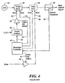
- FIG. 4 a diagram of an optical transmitter with a pulse modulator 36 and a data modulator 38 is shown.
- An optical feedback signal 39 provides control information to modulator controller 42.
- Modulator controller 42 provides three control signals related to producing the modulated optical signal.
- a pulse bias control signal 44 provides bias control to pulse modulator 36
- a data bias control signal 46 provides bias control to data modulator 38
- a phase control signal 48 provides phase control for phase shifters 50.
- modulator controller 42 monitors output optical power in optical feedback 39 and maintains a desired value for data bias signal 46, pulse bias signal 44 and phase control signal 48.
- Modulator controller 42 sets bias signals 44 and 46 and phase control signal 48 using a series of dithers to produce and maintain an optimal optical waveform over temperature, aging and other drift inducing characteristics.
- One way to measure the optimal optical waveform is to provide a low Bit Error Rate (BER) at the receiver to which the modulated optical signal is provided.
- BER Bit Error Rate
- Fluctuations in output optical power are influenced as a function of pulse bias 44, data bias 46 and phase control 48, to provide a three-dimensional basis for control of system operation in the optical transmitter of Fig. 4 .
- Transmitters typically include an optical modulator
- receivers typically include an optical demodulator
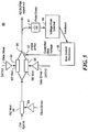
- Fig. 5 additional control parameters for a DQPSK transmitter 60 are used beyond those used for the RZ DPSK transmitter illustrated in Fig. 4 .
- DATA1 and DATA2 into data modulators 62, 63, respectively.
- biases for the data modulators there are two controls for pulse modulator 66, one for timing between clock signal 64 and input DATA1, and one for timing between clock signal 64 and input DATA2.
- pulse modulator 66 one for timing between clock signal 64 and input DATA1
- clock signal 64 and input DATA2 there are two controls for pulse modulator 66, one for timing between clock signal 64 and input DATA1, and one for timing between clock signal 64 and input DATA2.
- These two controls are similar to RZ DPSK clock controls for pulse modulator 36 shown in Fig. 4 and may be omitted for an RZ or DPSK modulation.
- a bias of ⁇ /2 between optical inputs DATA1 and DATA2 should be controlled to optimize transmitter performance. Furthermore, appropriate timing between input DATA1 and DATA2 at a data level should also be controlled.
- the control loops for DQPSK transmitter 60 are similar to those described for Fig. 4 with respect to the data modulator and the RZ timing in pulse modulator 66. In general, those control schemes use an optical power feedback to maintain appropriate bias settings. For example, referring to Fig. 4 , if the driving voltage of data modulator 38 is less than approximately 1.53 V ⁇ , the correct bias setting corresponds to a minimum of optical power output versus bias.
- RZ pulse modulator 36 may be a Mach-Zehnder (MZ) modulator, which can be driven by a full clock rate sinusoidal signal. That is, the signal frequency can equal the data signal rate frequency. Alternately, the RZ modulator can be driven by a half-rate signal. In the case of the full clock rate signal, the RZ bias is set to a quadrature. In the case of the half clock rate signal, the RZ bias can be set to a minimum or to a maximum transmission point.
- MZ Mach-Zehnder
- RZ DQPSK transmitter 60 there are some advantages available in RZ DQPSK transmitter 60 illustrated in Fig. 5 over prior optical transmitters. Because there are two data modulators, additional timing slots may be added in the second modulator in a Time Division Multiplexing (TDM) scheme. Also, different dither tone frequencies may be used for the two different data modulators. In addition, timing control between the RZ pulse carving and data streams can be controlled in different ways. For example, the system may control the path delays for input DATA1 and input DATA2, while omitting control for the delay path in RZ modulator 66. Alternately, the system may control the delays for paths in RZ modulator 66 and input DATA1, while omitting control for the path delay in input DATA2.
- TDM Time Division Multiplexing
- a parameter that should be controlled in RZ DQPSK transmitter 60 is the phase difference between an optical DATA1 signal and an optical DATA2 signal.
- This parameter can be referred to generally as a data bias phase shift.
- the data bias phase shift like other control parameters, depends upon a feedback value to stabilize or control variables in the system to produce the desired output. However, attempts to control the data bias phase shift using an optical power feedback, similar to other control parameters in the system, does not provide satisfactory control.
- the concept of using average output optical power as the feedback appears to provide some stability in the control loop to maintain the phase shift at the desired value of ⁇ /2.
- some desirable control parameters are achieved.
- a bias tone applied to a phase shifter obtains a control loop that minimizes the second harmonic frequency of the tone.
- the control loop feedback based on average output optical power is not as stable as desirable, due to the presence of random signal transmissions.
- the average output optical power should be independent of the relative bias between the two data signals. Accordingly, because the average output optical power feedback does not provide a consistent control result in the presence of random signal transmissions, alternate control schemes with improved control stability would be desirable.
- the disclosed system and method provide a technique for generating a feedback signal in an optical transmitter or receiver to achieve improved control of the phase difference between optical data signals applied to the transmitter or observed in the receiver.
- the disclosed system and method uses a combination of the two optical data signals to produce an optical signal that depends upon the mutual phase of the data signals.
- a schematic block diagram of the control loop in an RZ DQPSK transmitter 60 is illustrated in Fig. 5 .
- Transmitter 60 is similar to transmitter 24 illustrated in Fig. 2 , in which two different data paths are provided to encode a data stream 18.
- the two different data streams DATA1 and DATA2 provide modulation for MZ modulators 62, 63 to produce optical data signals transmitted from transmitter 60.
- a phase shifter 67 controls the phase shift between the optical DATA1 and DATA2 signals.
- the desired phase shift for the RZ DQPSK transmitter 60 between optical data signals DATA1 and DATA2 is ⁇ /2. Maintaining this phase shift can be challenging with component tolerances, non-linearities, operational variations over temperature and age and other system variations that contribute to changing the phase relationship between optical data signals DATA1 and DATA2. Accordingly, a control loop for the phase difference between data signals DATA1 and DATA2 should be robust, consistent and be precise over a long term period to accommodate variations in system parameters.
- Figs. 6a-6c various phase shifts between optical data signals DATA1 and DATA2 are illustrated.
- Fig. 6a is a graph illustrating light intensity output versus time for a phase shift that is 0 or ⁇ .
- the instantaneous optical fields interfere strongly with each other.
- the two input optical signals are phase modulated by the data streams, the resulting signal after combination of the streams is a strongly intensity modulated signal. A significant difference between the light intensity of various bits is observed.
- optical data signals taken at the outputs of modulator 62, 63 have data bits that can be cancelled or multiplied when combined to interfere with each other at point 68 in Fig. 5 .
- a bias shift of 3 ⁇ /4 results in high peak intensities and low level signal bit intensities similar to the situation illustrated in Fig. 6a .
- the biases provided in Fig. 6a and 6b illustrate how an inappropriate bias results in high signal peaks and low level signal bit values due to the interference of the signals and their respective phases.
- Fig. 6c the light intensities resulting from the correct bias phase shift between optical data signals DATA1 and DATA2 is illustrated.
- This desired signal phase shift results in the intensities of all data bits being substantially closer to each other in magnitude.
- the instantaneous optical fields are orthogonal to each other.
- the instantaneous intensities of each data bit adds to each other during interference, so that the combined output produces data bit intensities that are approximately 2 times that of the signal intensities prior to combination.
- Figs. 6a-6c are approximately the same.
- an optimum bias setting corresponding to ⁇ /2 or 3 ⁇ /2 for the phase difference between the data signals, can be controlled based on a minimum peak intensity of the combined data signals. This relationship is illustrated in Fig. 7 . Accordingly, peak signal intensity may be used as a feedback to control the phase difference between the different data paths.
- Voltage peak detector 69 obtains an input from photodiode 61, which converts optical signals to electrical signals in the feedback loop. Voltage peak detector 69 produces an indication of the output optical signal peak intensity, which is used by bias control 65 to control phase shifter 67 to minimize signal peak intensity.
- bias control 65 may produce a dither tone to be applied to phase shifter 67. Minimizing signal peak intensity should result in the desired phase shift of ⁇ /2 or 3 ⁇ /2.
- Photodiode 61 may be a fast photodiode to contribute to maintaining an appropriate loop speed and stability. By minimizing the signal from voltage peak detector 69, transmitter 60 can maintain an appropriate phase difference of ⁇ /2 or 3 ⁇ /2 between the two optical data signals DATA1 and DATA2.
- a graph of peak voltage versus phase difference for transmitter 60 is illustrated.
- the desired phase difference settings of 0.5 ⁇ and 1.5 ⁇ are observed as corresponding to minimums in the peak voltage. Accordingly, the control scheme that minimizes the peak voltage observed in the feedback loop provides the appropriate phase difference bias.
- the phase difference of ⁇ /2 corresponds to the non-inverted data, while the phase difference 3 ⁇ /2 corresponds to inverted data.
- the choice of bias of either ⁇ /2 or 3 ⁇ /2 for minimizing the feedback signal peak intensity may be made at calibration or during device initialization.
- phase shifter 67 Another technique for identifying appropriate control loop settings for the bias on phase shifter 67 is to observe the RF spectra of the feedback signals. As indicated by Figs. 6a-6c , the desired optical output has a very different RF spectra from the undesired optical output.
- the undesired optical output intensity signals have a strong intensity modulation and therefore contain a significant fraction of energy in midrange spectral components.
- the desired phase shift and resulting optical output intensity signals do not have a large fraction of energy in the midrange spectral components.
- voltage peak detector 69 illustrated in Fig. 5 may be replaced with an RF power detector that measures RF power in a spectral band between zero and the symbol rate frequencies. The RF power measured by the detector can be minimized to obtain the appropriate phase shift bias for controlling phase shifter 67.
- One advantage provided by the disclosed system and method is that there is no requirement to modify timing between data inputs DATA1 and DATA2 at a data level. That is, the actual data information provided by data paths DATA1 and DATA2 need not be shifted or modified in accordance with the present invention.
- the timing between input data paths DATA1 and DATA2 at a data level can be set during calibration or during device initialization, and is then maintained with the control loops related to RZ modulation and data modulation.
- Tunable DI 84 includes a phase shifter 86 for tuning through the application of a voltage from bias control 88.
- the actual control of the phase shift in DI 84 may be achieved with a number of techniques, including heating a portion of the mechanism of DI 84 or changing an optical path characteristic through stretching/compressing a material with a piezoelectric element, among other available techniques.
- Receiver 80 demodulates an input optical DPSK data signal, and should have an optimized phase shift control to appropriately deconstruct the input data signal with DI 84.
- an output electrical signal from balanced detector 85 is applied to voltage peak detector 82 to produce a feedback signal that may be used by bias control 88 to appropriately control phase shifter 86.
- bias control 88 to appropriately control phase shifter 86.
- the use of voltage peak detector 82 permits the determination of the appropriate control to apply to phase shifter 86 to maintaining the desired phase shift in DI 84.
- a graph of peak voltage versus phase offset is illustrated.
- the optimum bias settings for phase shifter 86 are 0, + ⁇ and - ⁇ .
- the graph is Fig. 9 demonstrates that the desired operational points for phase shifter 86 depends upon the points at which the peak voltage intensity at the output of balance detector 85 is maximized.
- the maximums of 0, + ⁇ and - ⁇ correspond to the non-inverted data and the inverted data, one of which can be chosen during calibration or device initialization.
- the appropriate phase shift for DI 84 can be maintained. Accordingly, a practical implementation of a control loop for the phase shift bias in DI 84 can be provided.
- receiver 80 may also use an RF power detector to produce a signal that can be maximized.
- the output voltage peak intensity or RF power changes to produce an indication of the appropriate control to be applied to phase shifter 86.
- the voltage peak intensity a maximum is desired.
- the RF power detector it is desirable to maximize RF power. Maximum RF power is generally obtained when the two optical pathways in DI 84 are appropriately shifted in phase so that each of the combined signal bits add up with constructive interference.
- Receiver 100 includes two DIs 103, 104, with controllable phase shifters 105, 106, respectively.
- Each branch 101, 102 of receiver 100 has a separate control loop that operates similarly to receiver 80 in Fig. 8 . Accordingly, a voltage peak intensity feedback is used to control phase shifters 105, 106 from each of the separate electrical outputs of balanced detectors 107, 108, respectively.
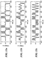
- Figs. 11a-11c illustrate the output signals at one of balanced detectors 107, 108.
- Fig. 11a corresponds to an incorrect phase shift setting of 0 or ⁇ , resulting in cancellation of some of the signal bits and increased magnitude of other signal bits.
- Fig. 11b illustrates a phase shift of ⁇ /8, where less cancellation takes place, but the phase shift is not optimal.
- Fig. 11c illustrates the desired phase shift of ⁇ /4 and the addition of signal bits upon being recombined to interfere with each other.
- the output voltage peak intensity therefore provides a useful means for controlling phase shifters 105, 106 to produce the desired phase shift, which can be maintained with a fair amount of precision.
- Figs. 12a-12c eye diagrams for different values of phase shift bias for DQPSK receiver 100 are illustrated. As can be seen, the eye diagrams of Fig. 12c are wide open with the desired phase shift bias of ⁇ /4.
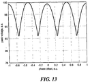
- a graph of peak voltage versus phase offset for an output of one of balanced detectors 107, 108 is illustrated.
- the desired phase shift bias settings for DQPSK receiver 100 are ⁇ /4, - ⁇ /4, 3 ⁇ /4 and -3 ⁇ /4.
- the desired operating points for phase shift bias correspond to minimums of the wave form plotted in Fig. 13 .
- the feedback control loop based on output voltage peak intensity detection seeks to control phase shifters 105, 106 to minimize output voltage peak intensity.
- the four minima illustrated in Fig. 13 correspond to non-inverted and inverted data, the use of either of which can be chosen during calibration or device initialization.
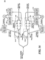
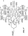
- Figs. 14-17 DQPSK receivers with various techniques for detecting peak signal intensity are illustrated.
- one arm of balanced detectors 107, 108 is used to obtain a voltage peak intensity indication.
- the output is taken from one of the 2 photodiodes in balanced detectors 107, 108 to determine output voltage peak intensity.
- a single path of the optical output of DI 103, 104 in a receiver 150 is supplied to a fast photodetector 151, 152, respectively.
- the fast photodetector used in receiver 150 for each of DI 103, 104 can provide a faster response time for the control loop to obtain a fine phase adjustment.
- the use of a fast photodetector also permits implementation of the present invention without modifying existing receiver components.
- a receiver 160 includes output voltage peak detection in both paths of balanced detectors 107, 108.
- the output voltage of each path is supplied to a voltage peak intensity detector.
- the output of the voltage peak intensity detector is summed to produce the proportional signal provided to a bias control 162, 169.
- the output of voltage peak intensity detector 165 and 167 is summed and applied to a bias control 169 to control phase shifter 105.
- the peak intensity signals generated in voltage peak detectors 165, 167 and 166, 168 add together to produce a greater amplitude feedback signal that produces enhanced control of phase shifters 105, 106, respectively.
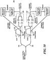
- receiver 170 detects signal peak intensity from feedback taken in both optical paths in each of balanced detectors 107, 108.
- the feedback is taken before the PIN diodes in balanced detectors 107, 108, so that an optical signal is processed for feedback purposes.
- Fast photodetectors 171-174 convert the optical signals that are output from DIs 103, 104 into a voltage applied to voltage peak intensity detectors 175-178, respectively.
- Summing junctions 179, 180 sum the output of voltage peak intensity detectors 175, 177 and 176, 178, respectively, with the summed voltage signal being applied to a bias control 181, 182.
- Bias control 181 and 182 control phase shifters 105, 106 to maintain the desired phase difference in DIs 103, 104 based on minimizing the peak signal intensity of the feedback signal.
- One advantage provided by this configuration is to permit the present invention to be applied to existing systems without modifying the system components, such as DIs 103, 104 or balanced detectors 107, 108.
- optical signal peak intensity detector without having to convert feedback signals to electrical form.
- Such a detector can provide faster control loop response and improved stability control.
- a feedback signal may be generated that is proportional to a data error rate in a Forward Error Correction (FEC) IC, for example.
- FEC Forward Error Correction
- the optical transmitter or receiver control loops use the proportional signal derived from the FEC to drive the data error rate to a minimum.
- control loops using the FEC are active in different time slots to avoid interference with each other.
- the time slot configuration may be a Time Division Multiplexing (TDM) scheme, as previously described.
Description
- This application claims benefit of
U.S. Provisional Application No. 60/710,749 filed August 24, 2005 - Differential Phased Shift Keying (DPSK, also known as Differential Binary Phased Shift Keying DBPSK) and Differential Quadrature Phased Shift Keying (DQPSK) are very attractive modulation formats for optical data transmission. When used with a balanced direct detection receiver, DPSK outperforms conventional on-off keying receiver sensitivity by approximately 3 dB. Dense Wavelength Division Multiplexing (DWDM) transmission up to 10,000km has been demonstrated at 40Gbit/s using DPSK modulation format. DQPSK has a symbol rate that is half of the data rate. For example, for a 43Gb/s data rate, a 21.5 gigasymbol per second rate is used. As a result, DQPSK has a narrower spectral bandwidth, greater chromatic dispersion tolerance and greater tolerance with respect to polarization mode dispersion (PMD) than traditional formats or DPSK.
- DPSK and DQPSK can be non-return-to-zero NRZ-type modulated, or, if a return-to-zero (RZ) pulse carver is added to the transmitter, RZ-type modulated. RZ-type usually outperforms NRZ-type formats in performance based on optical signal-to-noise ratio (OSNR) sensitivity and robustness with respect to nonlinearity.
- DPSK and DQPSK modulation formats require rather complicated transmitters and receivers.
Figs. 1-3 illustratetransmitters receivers transmitters receivers transmitters receivers - Optical receivers include asymmetric Mach-Zehnder interferometers, also commonly referred to as delay interferometers (DIs), which act as optical DPSK/DQPSK demodulators, and balanced photodetectors. The time delay between the two arms of the interferometer is approximately an integer number of the time symbol slots of the optical DPSK/DQPSK data signal:

PIN diodes receivers - For a DPSK receiver to operate properly, the asymmetric Mach-Zehnder interferometer or DI should be accurately phased-tuned or biased. DPSK
receiver 22 uses oneDI 21, and the optimum phase bias between the two arms is π or 0. DQPSKreceiver 26 uses twoDIs - The modulators in DPSK and
DQPSK transmitters DQPSK transmitter 24 consists of two parallel Mach-Zehnder (MZ)modulators 29. The optical signals frommodulators 29 are combined to produce an RZ DQPSK output. The proper relative optical phase or bias between these signals of n/2 is set by aphase shifter 32. In known systems,phase shifter 32 operates on the basis of optical power feedback. -
EP1513273(A2 ) discloses a method for receiving an optical signal, comprising: splitting an ingress signal into a first portion and second portion; inducing a relative delay between the first portion and the second portion; optically interfering the first and second portions to generate at least one interfered signal; monitoring an optical power of a monitored signal at least based on the at least one interfered signal; and adjusting the relative delay based on the optical power. -
US20050088659 proposes a method for feedback control, in which a portion of a data signal is split and rectified and the signal intensity is detected with slow speed electronics for improving the control of a delay line interferometer (DLI) used in optical data transmission. A control signal is generated and fed back to the DLI based on the detected signal intensity. The invention further proposes a device provided with a DLI, a first and second optoelectronic component, and a differential amplifier. -
WO2004005972 discloses an optical device, comprising: a first Mach-Zehnder modulator that produces a first output; a second Mach-Zehnder modulator that produces a second output; a splitter coupled to the first and second Mach-Zehnder modulators; a combiner that combines the first and second outputs; and a phase shifter coupled to the first and second Mach-Zehnder modulators, wherein the first Mach-Zehnder modulator, the second Mach-Zehnder modulator, the splitter, the combiner and the phase shifter are formed as part of a single planar chip made of electro-optical material. - According to the present invention, there is provided a method for controlling an optical modulator or demodulator, and an optical modulator or demodulator, a DPSK or DQPSK transmitter, and a DPSK or DQPSK receiver, as set forth in the appended claims.
- Briefly described, the present disclosure provides a system and method for an improved control of optical transmitters and receivers to provide stable operation with changes in system parameters such as may be caused by temperature or aging. The disclosed system and method identifies and utilizes a peak intensity measurement of an output signal in the transmitter or receiver to optimize control settings for transmitter or receiver components.
- According to an exemplary embodiment, bias settings for an optical communication device are controlled based on feedback influenced by output signal peak intensity. The output signal peak intensity provides a measurement dependent upon the phase difference between two optical data signals. Accordingly, the output signal peak intensity feedback is used to control the phase bias between two optical signals to optimize the phase difference. In one embodiment, the minimum output signal peak intensity determines the optimum bias settings for the phase difference between the two optical signals. In another embodiment, the maximum output signal peak intensity is used.
- According to an aspect of the disclosed system and method, a dither tone applied to a phase shifter component controls the phase shift to obtain an improved phase difference stability. The dither tone can be developed based on the feedback from the optical communication device output applied to a voltage peak detector. The feedback may include a fast photodiode coupled to the output optical signal. Alternately, or in addition, the feedback signal can be an available electrical output from the optical communication device.
- The present invention is applicable to DPSK and DQPSK transmitters and receivers, operating with RZ or NRZ modulation. Transmitters typically include an optical modulator, while receivers typically include an optical demodulator.
- In the case of a DQPSK transmitter, the voltage peak detector signal generates bias control settings to adjust the phase shifter in one branch of the two data signals to minimize the output signal peak intensity. The appropriate bias applied to the phase shifter is n/2 or 3n/2. The n/2 bias setting optimizes the phase difference of the two data branches, while the 3n/2 bias setting corresponds to optimizing the inverted data.
- The feedback loop for optimizing phase difference between the two optical branches may additionally include an RF power detector for measuring RF power in the spectral band between zero and the symbol rate frequencies. The RF power detector can detect midrange spectral components to determine if the modulation bias is correct. With incorrect modulation bias, a significant fraction of signal energy lies in midrange spectral components. Correct modulation produces an RF power signature with less concentrated energy in the midrange spectral components. The control loop can adjust phase bias settings to reduce the amount of energy in midrange spectral components to optimize system output.
- According to another exemplary embodiment, the disclosed system and method optimizes operation of a DPSK receiver by inspection of a voltage peak detector feedback. A phase shifter bias is controlled to maximize the peak voltage at the output of the DPSK receiver. Optimum settings for the bias are 0, +n and -n. According to an aspect of the present invention, the stabilization phase bias is chosen based on one of the two maxima during calibration or system initialization.
- According to another exemplary embodiment, the output of a DQPSK receiver is optimized on the basis of detection of a peak voltage feedback. The output voltage is applied to a voltage peak detector, which in turn supplies a proportional signal to phase bias electronics that control the phase shifter to attain an optimal phase shift. The DQPSK receiver includes two branches, and can have two separate voltage peak detectors and bias control for two different phase shifters in the separate branches. In the DQPSK receiver, the optimum phase shifter bias corresponds to a minima of the peak voltage detected in the feedback control loop. There are two minima at +n/4 and -n/4 corresponding to the two DI modulators, and another two minima at +3n/4 and -3n/4 that correspond to modulator settings for inverted data. The phase shifter bias applied by the feedback control loops seeks to adjust the phase shift to minimize the peak output voltage for each of the corresponding balanced receivers in the DQPSK receiver. The choice of the minima used to control the phase shift of the two DI demodulators may be chosen during calibration or receiver initialization.
- In the disclosed system and method, an RF power detector may additionally be used to control the phase shift bias to minimize the RF power related to the receiver output of the DQPSK receiver.
- According to an advantage of the present invention, the peak voltage feedback signal may be obtained at an output of the balanced detector or at the optical output of one or more arms of the separate DI demodulators. The phase shift bias control may be based on voltage peak detection from a single optical arm of the balanced detector in the DQPSK receiver, or both optical arms. Alternately, or in addition, the peak voltage detection may be obtained at the electrical output of the different arms of the balance detector, or both arms together.
- A feedback control loop for an optical transmitter or receiver may additionally use a signal that is proportional to a data error rate to provide a bias for a phase shifter. The control loop attempts to adjust the bias on the phase shifter to minimize the signal proportional to the data error rate. The data error rate may be taken from a Forward Error Correction (FEC) chip, for example. The control loops using the signal that is proportional to the data error rate are active in different time slots in a time division multiplexing (TDM) type system to avoid interference between control loops for two separate DI demodulators.
- The disclosed system and method are described in greater detail below, with reference to the accompanying drawings, in which:
-
Figs. 1a, 1b illustrate a DPSK transmitter and receiver, respectively; -
Fig. 2 is a schematic block diagram of an RZ DQPSK transmitter; -
Fig. 3 is a schematic block diagram of an RZ DQPSK receiver. -
Fig. 4 is a block diagram of a known optical transmitter; -
Fig. 5 is a schematic block diagram of an RZ DQPSK transmitter in accordance with the present invention; -
Figs. 6a-6c are graphical plots of output light intensity versus time for an RZ DQPSK transmitter; -
Fig. 7 is a graphical plot of output peak intensity voltage versus phase difference for a DQPSK transmitter; -
Fig. 8 is a schematic block diagram of a DPSK receiver with a feedback control loop in accordance with the present invention; -
Fig. 9 is a graphical plot of output peak intensity voltage versus phase difference for a DPSK balanced detector; -
Fig. 10 is a schematic block diagram of a DQPSK receiver with feedback signals taken from outputs of balanced detectors; -
Figs. 11a-11c are graphical plots of output signal voltage versus time for an RZ DQPSK balanced detector; -
Figs. 12a-12c are eye diagrams for the respective signal plots shown inFigs. 11a-11c ; -
Fig. 13 is a graphical plot of output peak intensity voltage versus phase difference at an output of a DQPSK balanced detector; -
Fig. 14 is a schematic block diagram of a DQPSK receiver with feedback signals taken from a photodiode in each balanced detector; -
Fig. 15 is a schematic block diagram of a DQPSK receiver with feedback signals taken from an optical output of a delay interferometer; -
Fig. 16 is a schematic block diagram of a DQPSK receiver with feedback signals taken from two photodiodes in each of the balanced detectors; and -
Fig. 17 is a schematic block diagram of a DQPSK receiver with feedback signals taken from two optical outputs at each of the delay interferometers. - Reference is made to
U.S. Provisional Application No. 60/710,749, filed august 24, 2005 - Referring now to
Fig. 4 , a diagram of an optical transmitter with apulse modulator 36 and adata modulator 38 is shown. Anoptical feedback signal 39 provides control information tomodulator controller 42.Modulator controller 42 provides three control signals related to producing the modulated optical signal. A pulse bias control signal 44 provides bias control topulse modulator 36, a databias control signal 46 provides bias control todata modulator 38 and aphase control signal 48 provides phase control forphase shifters 50. - In general,
modulator controller 42 monitors output optical power inoptical feedback 39 and maintains a desired value for data biassignal 46, pulse bias signal 44 andphase control signal 48.Modulator controller 42 sets bias signals 44 and 46 andphase control signal 48 using a series of dithers to produce and maintain an optimal optical waveform over temperature, aging and other drift inducing characteristics. One way to measure the optimal optical waveform is to provide a low Bit Error Rate (BER) at the receiver to which the modulated optical signal is provided. Fluctuations in output optical power are influenced as a function of pulse bias 44, data bias 46 andphase control 48, to provide a three-dimensional basis for control of system operation in the optical transmitter ofFig. 4 . - The disclosed system and method described below applies to DPSK and DQPSK transmitters and receivers, operating with RZ or NRZ modulation. Transmitters typically include an optical modulator, while receivers typically include an optical demodulator.
- Referring now to
Fig. 5 , additional control parameters for aDQPSK transmitter 60 are used beyond those used for the RZ DPSK transmitter illustrated inFig. 4 . Because there are two data inputs, DATA1 and DATA2, intodata modulators pulse modulator 66, one for timing betweenclock signal 64 and input DATA1, and one for timing betweenclock signal 64 and input DATA2. These two controls are similar to RZ DPSK clock controls forpulse modulator 36 shown inFig. 4 and may be omitted for an RZ or DPSK modulation. - In addition to the above-described signals and controls, a bias of π/2 between optical inputs DATA1 and DATA2 should be controlled to optimize transmitter performance. Furthermore, appropriate timing between input DATA1 and DATA2 at a data level should also be controlled. The control loops for
DQPSK transmitter 60 are similar to those described forFig. 4 with respect to the data modulator and the RZ timing inpulse modulator 66. In general, those control schemes use an optical power feedback to maintain appropriate bias settings. For example, referring toFig. 4 , if the driving voltage ofdata modulator 38 is less than approximately 1.53 Vπ, the correct bias setting corresponds to a minimum of optical power output versus bias. If the driving voltage fordata modulator 38 is higher than approximately 1.53 Vπ, the correct bias setting corresponds to a maximum of optical energy output versus bias. In addition, RZ versus data timing in the optical transmitter ofFig. 4 is set to a maximum optical energy output.RZ pulse modulator 36 may be a Mach-Zehnder (MZ) modulator, which can be driven by a full clock rate sinusoidal signal. That is, the signal frequency can equal the data signal rate frequency. Alternately, the RZ modulator can be driven by a half-rate signal. In the case of the full clock rate signal, the RZ bias is set to a quadrature. In the case of the half clock rate signal, the RZ bias can be set to a minimum or to a maximum transmission point. - There are some advantages available in
RZ DQPSK transmitter 60 illustrated inFig. 5 over prior optical transmitters. Because there are two data modulators, additional timing slots may be added in the second modulator in a Time Division Multiplexing (TDM) scheme. Also, different dither tone frequencies may be used for the two different data modulators. In addition, timing control between the RZ pulse carving and data streams can be controlled in different ways. For example, the system may control the path delays for input DATA1 and input DATA2, while omitting control for the delay path inRZ modulator 66. Alternately, the system may control the delays for paths inRZ modulator 66 and input DATA1, while omitting control for the path delay in input DATA2. - A parameter that should be controlled in
RZ DQPSK transmitter 60 is the phase difference between an optical DATA1 signal and an optical DATA2 signal. This parameter can be referred to generally as a data bias phase shift. The data bias phase shift, like other control parameters, depends upon a feedback value to stabilize or control variables in the system to produce the desired output. However, attempts to control the data bias phase shift using an optical power feedback, similar to other control parameters in the system, does not provide satisfactory control. - The concept of using average output optical power as the feedback appears to provide some stability in the control loop to maintain the phase shift at the desired value of π/2. For example, with the control loop set to achieve the maximum derivative of the average output optical power with respect to the controlled data bias phase shift, some desirable control parameters are achieved. In this type of control, a bias tone applied to a phase shifter obtains a control loop that minimizes the second harmonic frequency of the tone. However, the control loop feedback based on average output optical power is not as stable as desirable, due to the presence of random signal transmissions. When a random signal is transmitted, the average output optical power should be independent of the relative bias between the two data signals. Accordingly, because the average output optical power feedback does not provide a consistent control result in the presence of random signal transmissions, alternate control schemes with improved control stability would be desirable.
- The disclosed system and method provide a technique for generating a feedback signal in an optical transmitter or receiver to achieve improved control of the phase difference between optical data signals applied to the transmitter or observed in the receiver. The disclosed system and method uses a combination of the two optical data signals to produce an optical signal that depends upon the mutual phase of the data signals. A schematic block diagram of the control loop in an
RZ DQPSK transmitter 60 is illustrated inFig. 5 .Transmitter 60 is similar totransmitter 24 illustrated inFig. 2 , in which two different data paths are provided to encode adata stream 18. Referring toFig. 5 , the two different data streams DATA1 and DATA2 provide modulation forMZ modulators transmitter 60. Aphase shifter 67 controls the phase shift between the optical DATA1 and DATA2 signals. The desired phase shift for theRZ DQPSK transmitter 60 between optical data signals DATA1 and DATA2 is π/2. Maintaining this phase shift can be challenging with component tolerances, non-linearities, operational variations over temperature and age and other system variations that contribute to changing the phase relationship between optical data signals DATA1 and DATA2. Accordingly, a control loop for the phase difference between data signals DATA1 and DATA2 should be robust, consistent and be precise over a long term period to accommodate variations in system parameters. - Various combinations of the two optical signals DATA1 and DATA2 were experimented with to attempt to obtain a desired control with an appropriate phase shift. Referring for a moment to
Figs. 6a-6c , various phase shifts between optical data signals DATA1 and DATA2 are illustrated.Fig. 6a is a graph illustrating light intensity output versus time for a phase shift that is 0 or π. In the light intensity peaks observed inFig. 6a , the instantaneous optical fields interfere strongly with each other. Because the two input optical signals are phase modulated by the data streams, the resulting signal after combination of the streams is a strongly intensity modulated signal. A significant difference between the light intensity of various bits is observed. That is, while some bits have an intensity that is close to 0, other bits have an intensity that is approximately 4 times that of the signal bits prior to interference through the combination of optical data signals DATA1 and DATA2. That is, the optical data signals taken at the outputs ofmodulator point 68 inFig. 5 . - Referring to
Fig. 6b , a bias shift of 3π/4 results in high peak intensities and low level signal bit intensities similar to the situation illustrated inFig. 6a . The biases provided inFig. 6a and 6b illustrate how an inappropriate bias results in high signal peaks and low level signal bit values due to the interference of the signals and their respective phases. - Referring now to
Fig. 6c , the light intensities resulting from the correct bias phase shift between optical data signals DATA1 and DATA2 is illustrated. This desired signal phase shift results in the intensities of all data bits being substantially closer to each other in magnitude. With the π/2 or 3π/2 phase shift biases for the phase shift between the optical data paths, the instantaneous optical fields are orthogonal to each other. As a result, the instantaneous intensities of each data bit adds to each other during interference, so that the combined output produces data bit intensities that are approximately 2 times that of the signal intensities prior to combination. By observing the differences between the graph inFig. 6c and those inFigs. 6a and 6b , a control scheme might be envisioned that focuses on peak signal intensity values. - Interestingly, the average optical power in each of the case of
Figs. 6a-6c are approximately the same. However, because of the differences in the peak signal intensities versus phase bias, a consistent and stable control may be realized based on the peak signal intensities. For example, an optimum bias setting, corresponding to π/2 or 3π/2 for the phase difference between the data signals, can be controlled based on a minimum peak intensity of the combined data signals. This relationship is illustrated inFig. 7 . Accordingly, peak signal intensity may be used as a feedback to control the phase difference between the different data paths. - Referring again to
Fig. 5 , a feedback loop illustrating the use of avoltage peak detector 69 is illustrated.Voltage peak detector 69 obtains an input fromphotodiode 61, which converts optical signals to electrical signals in the feedback loop.Voltage peak detector 69 produces an indication of the output optical signal peak intensity, which is used bybias control 65 to controlphase shifter 67 to minimize signal peak intensity. In practice,bias control 65 may produce a dither tone to be applied tophase shifter 67. Minimizing signal peak intensity should result in the desired phase shift of π/2 or 3π/2. -
Photodiode 61 may be a fast photodiode to contribute to maintaining an appropriate loop speed and stability. By minimizing the signal fromvoltage peak detector 69,transmitter 60 can maintain an appropriate phase difference of π/2 or 3π/2 between the two optical data signals DATA1 and DATA2. - Referring now to
Fig. 7 , a graph of peak voltage versus phase difference fortransmitter 60 is illustrated. The desired phase difference settings of 0.5π and 1.5π are observed as corresponding to minimums in the peak voltage. Accordingly, the control scheme that minimizes the peak voltage observed in the feedback loop provides the appropriate phase difference bias. The phase difference of π/2 corresponds to the non-inverted data, while the phase difference 3π/2 corresponds to inverted data. The choice of bias of either π/2 or 3π/2 for minimizing the feedback signal peak intensity may be made at calibration or during device initialization. - Another technique for identifying appropriate control loop settings for the bias on
phase shifter 67 is to observe the RF spectra of the feedback signals. As indicated byFigs. 6a-6c , the desired optical output has a very different RF spectra from the undesired optical output. The undesired optical output intensity signals have a strong intensity modulation and therefore contain a significant fraction of energy in midrange spectral components. The desired phase shift and resulting optical output intensity signals do not have a large fraction of energy in the midrange spectral components. Accordingly,voltage peak detector 69 illustrated inFig. 5 may be replaced with an RF power detector that measures RF power in a spectral band between zero and the symbol rate frequencies. The RF power measured by the detector can be minimized to obtain the appropriate phase shift bias for controllingphase shifter 67. - One advantage provided by the disclosed system and method is that there is no requirement to modify timing between data inputs DATA1 and DATA2 at a data level. That is, the actual data information provided by data paths DATA1 and DATA2 need not be shifted or modified in accordance with the present invention. The timing between input data paths DATA1 and DATA2 at a data level can be set during calibration or during device initialization, and is then maintained with the control loops related to RZ modulation and data modulation.
- Referring now to
Fig. 8 , aDPSK receiver 80 is illustrated with avoltage peak detector 82 in accordance with the present invention.Tunable DI 84 includes aphase shifter 86 for tuning through the application of a voltage frombias control 88. The actual control of the phase shift inDI 84 may be achieved with a number of techniques, including heating a portion of the mechanism ofDI 84 or changing an optical path characteristic through stretching/compressing a material with a piezoelectric element, among other available techniques.Receiver 80 demodulates an input optical DPSK data signal, and should have an optimized phase shift control to appropriately deconstruct the input data signal withDI 84. In accordance with the present invention, an output electrical signal frombalanced detector 85 is applied tovoltage peak detector 82 to produce a feedback signal that may be used bybias control 88 to appropriately controlphase shifter 86. The use ofvoltage peak detector 82 permits the determination of the appropriate control to apply tophase shifter 86 to maintaining the desired phase shift inDI 84. - Referring to
Fig. 9 , a graph of peak voltage versus phase offset is illustrated. ForDPSK receiver 80 illustrated inFig. 8 , the optimum bias settings forphase shifter 86 are 0, +π and -π. The graph isFig. 9 demonstrates that the desired operational points forphase shifter 86 depends upon the points at which the peak voltage intensity at the output ofbalance detector 85 is maximized. The maximums of 0, +π and -π correspond to the non-inverted data and the inverted data, one of which can be chosen during calibration or device initialization. By maximizing the output peak voltage intensity of the receiver ofFig. 8 , the appropriate phase shift forDI 84 can be maintained. Accordingly, a practical implementation of a control loop for the phase shift bias inDI 84 can be provided. - In addition to using the output voltage peak intensity,
receiver 80 may also use an RF power detector to produce a signal that can be maximized. As described above, ifphase shifter 86 operates at a point away from the desired phase offset, the output voltage peak intensity or RF power changes to produce an indication of the appropriate control to be applied tophase shifter 86. In the case of the voltage peak intensity, a maximum is desired. In the case of the RF power detector, it is desirable to maximize RF power. Maximum RF power is generally obtained when the two optical pathways inDI 84 are appropriately shifted in phase so that each of the combined signal bits add up with constructive interference. - Referring now to
Fig. 10 , aDQPSK receiver 100 is illustrated.Receiver 100 includes twoDIs controllable phase shifters branch receiver 100 has a separate control loop that operates similarly toreceiver 80 inFig. 8 . Accordingly, a voltage peak intensity feedback is used to controlphase shifters balanced detectors -
Figs. 11a-11c illustrate the output signals at one ofbalanced detectors Fig. 11a corresponds to an incorrect phase shift setting of 0 or π, resulting in cancellation of some of the signal bits and increased magnitude of other signal bits.Fig. 11b illustrates a phase shift of π/8, where less cancellation takes place, but the phase shift is not optimal.Fig. 11c illustrates the desired phase shift of π/4 and the addition of signal bits upon being recombined to interfere with each other. The output voltage peak intensity therefore provides a useful means for controllingphase shifters - Referring to
Figs. 12a-12c , eye diagrams for different values of phase shift bias forDQPSK receiver 100 are illustrated. As can be seen, the eye diagrams ofFig. 12c are wide open with the desired phase shift bias of π/4. - Referring to
Fig. 13 , a graph of peak voltage versus phase offset for an output of one ofbalanced detectors DQPSK receiver 100 are π/4, -π/4, 3π/4 and -3π/4. The desired operating points for phase shift bias correspond to minimums of the wave form plotted inFig. 13 . Accordingly, the feedback control loop based on output voltage peak intensity detection seeks to controlphase shifters Fig. 13 correspond to non-inverted and inverted data, the use of either of which can be chosen during calibration or device initialization. - Referring now to
Figs. 14-17 , DQPSK receivers with various techniques for detecting peak signal intensity are illustrated. InFig. 14 , one arm ofbalanced detectors balanced detectors - Referring to
Fig. 15 , a single path of the optical output ofDI receiver 150 is supplied to afast photodetector receiver 150 for each ofDI - Referring to
Fig. 16 , areceiver 160 includes output voltage peak detection in both paths ofbalanced detectors bias control peak intensity detector bias control 169 to controlphase shifter 105. By providing two feedback signals for eachbalanced detector voltage peak detectors phase shifters - Referring to
Fig. 17 ,receiver 170 detects signal peak intensity from feedback taken in both optical paths in each ofbalanced detectors balanced detectors DIs junctions peak intensity detectors bias control Bias control control phase shifters DIs DIs balanced detectors - It is also possible to use an optical signal peak intensity detector without having to convert feedback signals to electrical form. Such a detector can provide faster control loop response and improved stability control.
- While a control scheme for stabilizing a phase difference in optical transmitters and receivers based on peak signal intensity has been described, additional or alternate control criteria are available. For example, a feedback signal may be generated that is proportional to a data error rate in a Forward Error Correction (FEC) IC, for example. The optical transmitter or receiver control loops use the proportional signal derived from the FEC to drive the data error rate to a minimum. In the cases where two DIs are used in the optical device, control loops using the FEC are active in different time slots to avoid interference with each other. The time slot configuration may be a Time Division Multiplexing (TDM) scheme, as previously described.
Claims (26)
- In an optical communication system, a method for controlling an optical modulator or demodulator having at least two optical paths (DATA 1, DATA 2) therein, each optical path being configured to carry an optical data signal, comprising:combining in the modulator or demodulator the optical data signals from the at least two optical paths to produce at least one resultant signal;characterized bymonitoring peak intensities of the at least one resultant signal; andadjusting a phase difference between the optical data signals to influence the peak intensity of the at least one resultant signal to achieve a predetermined characteristic.
- The method according to claim 1, further comprising adjusting the phase difference between the optical data signals to minimize the peak intensity of the at least one resultant signal.
- The method according to claim 1, further comprising adjusting the phase difference between the optical data signals to maximize the peak intensity of the at least one resultant signal.
- The method according to claim 1, further comprising employing the method to control the modulator in a DPSK transmitter.
- The method according to claim 1, further comprising employing the method to control the modulator in a DQPSK transmitter.
- The method according to claim 1, further comprising employing the method to control the demodulator in a DPSK receiver.
- The method according to claim 1, further comprising employing the method to control the demodulator in a DQPSK receiver.
- The method according to claim 4, further comprising employing RZ modulation in the DPSK transmitter.
- The method according to claim 4, further comprising employing NRZ modulation in the DPSK transmitter.
- The method according to claim 4, further comprising producing an optical signal as the at least one resultant signal.
- The method according to claim 5, further comprising employing RZ modulation in the DQPSK transmitter.
- The method according to claim 5, further comprising employing NRZ modulation in the DQPSK transmitter.
- The method according to claim 5, further comprising producing an optical signal as the at least one resultant signal.
- The method according to claim 6, further comprising:combining the optical data signals to produce two resultant optical signals; andapplying the two resultant optical signals to a balanced detector to produce an electrical signal as the at least one resultant signal.
- The method according to claim 7, further comprising:combining the optical data signals to produce two resultant optical signals; andapplying the two resultant optical signals to a balanced detector to produce an electrical signal as the at least one resultant signal.
- The method according to claim 6, further comprising:monitoring a data error rate of a received optical signal; andadjusting the phase difference based on the data error rate.
- The method according to claim 7, further comprising:monitoring a data error rate of a received optical signal; andadjusting the phase difference based on the data error rate.
- The method according to claim 1, further comprising employing an RF power detector to monitor peak intensities.
- An optical modulator or demodulator having at least two optical paths, each path being configured to carry an optical data signal, the modulator or demodulator comprising:an interferometer having at least two optical paths configured to combine at least two optical data signals (DATA 1, DATA 2) to produce at least one resultant signal;characterized by:a peak intensity detector (69) configured to detect a peak intensity of the at least one resultant signal; andat least one phase shifter (67) coupled to the peak intensity detector (69) and one of the at least two optical paths and configured to adjust a phase difference between the at least two optical data signals to influence the peak intensity of the at least one resultant signal to achieve a predetermined characteristic.
- The optical modulator or demodulator according to claim 19, wherein the peak intensity detector further comprises an RF power detector.
- A DPSK transmitter comprising the modulator according to claim 19.
- A DQPSK transmitter comprising the modulator according to claim 19.
- A DPSK receiver comprising the demodulator according to claim 19.
- A DQPSK receiver comprising the demodulator according to claim 19.
- The receiver according to claim 23, further comprising:two resultant optical signals produced by the interferometer; anda balanced detector coupled to the interferometer to receive the two resultant optical signals and produce at least one electrical signal as the at least one resultant signal.
- The receiver according to claim 24, further comprising:two resultant optical signals produced by the interferometer; anda balanced detector coupled to the interferometer to receive the two resultant optical signals and produce at least one electrical signal as the at least one resultant signal.
Applications Claiming Priority (2)
| Application Number | Priority Date | Filing Date | Title |
|---|---|---|---|
| US71074905P | 2005-08-24 | 2005-08-24 | |
| PCT/US2006/033064 WO2007025037A2 (en) | 2005-08-24 | 2006-08-24 | Method and apparatus for control of dpsk and dqpsk receivers and transmitters |
Publications (3)
| Publication Number | Publication Date |
|---|---|
| EP1917742A2 EP1917742A2 (en) | 2008-05-07 |
| EP1917742A4 EP1917742A4 (en) | 2012-08-08 |
| EP1917742B1 true EP1917742B1 (en) | 2016-07-06 |
Family
ID=37772382
Family Applications (1)
| Application Number | Title | Priority Date | Filing Date |
|---|---|---|---|
| EP06802255.7A Active EP1917742B1 (en) | 2005-08-24 | 2006-08-24 | Method and apparatus for control of dpsk and dqpsk receivers and transmitters |
Country Status (6)
| Country | Link |
|---|---|
| US (2) | US7986885B2 (en) |
| EP (1) | EP1917742B1 (en) |
| JP (1) | JP4818367B2 (en) |
| CN (2) | CN101297489A (en) |
| CA (1) | CA2620836A1 (en) |
| WO (1) | WO2007025037A2 (en) |
Families Citing this family (59)
| Publication number | Priority date | Publication date | Assignee | Title |
|---|---|---|---|---|
| US7995925B2 (en) * | 2003-09-22 | 2011-08-09 | Celight, Inc. | Optical receiver using beam combining and system using the same |
| US7974543B2 (en) * | 2003-09-22 | 2011-07-05 | Celight, Inc. | Optical receiver and a free-space optical communications using the same |
| US7961997B2 (en) * | 2003-09-22 | 2011-06-14 | Celight, Inc. | Space diversity optical receiver and system and method using the same |
| US7949262B2 (en) * | 2003-09-22 | 2011-05-24 | Celight, Inc. | Space diversity receiver for optical communications |
| US20060088321A1 (en) * | 2004-10-25 | 2006-04-27 | Cheung Peter Y | Closed loop RZ-DPSK alignment for optical communications |
| CN101297489A (en) * | 2005-08-24 | 2008-10-29 | 名坛若公司 | Method and apparatus for control of DPSK and DQPSK receivers and transmitters |
| DE102005041368A1 (en) * | 2005-08-31 | 2007-03-01 | Siemens Ag | Demodulation method for optical differential phase shift keying (DPSK) binary signals, involves demodulating phase-modulated and amplitude-modulated optical DPSK binary signal and evaluating phase and amplitude data of demodulated signal |
| ATE390768T1 (en) * | 2005-11-25 | 2008-04-15 | Alcatel Lucent | FIBER OPTICAL TRANSMISSION SYSTEM, TRANSMITTER AND RECEIVER FOR DQPSK MODULATED SIGNALS AND ASSOCIATED STABILIZATION METHOD |
| EP2011258B1 (en) | 2006-04-26 | 2017-05-17 | Oclaro, Inc. | Partial dpsk (pdpsk) transmission systems |
| JP4678653B2 (en) * | 2006-05-09 | 2011-04-27 | 富士通株式会社 | Optical transmitter |
| JP4983178B2 (en) * | 2006-09-15 | 2012-07-25 | 富士通株式会社 | Differential quadrature phase-shift keying optical receiver circuit |
| JP2008141670A (en) * | 2006-12-05 | 2008-06-19 | Fujitsu Ltd | Dqpsk modulation apparatus, optical transmission device and dqpsk modulation method |
| JP2008219765A (en) * | 2007-03-07 | 2008-09-18 | Nec Corp | Optical receiver and balance adjusting method |
| JP5211528B2 (en) * | 2007-03-29 | 2013-06-12 | 富士通株式会社 | Optical modulation device and optical modulation system switching method |
| JP5092827B2 (en) * | 2007-03-29 | 2012-12-05 | 富士通株式会社 | Optical DQPSK receiver and abnormality detection control method |
| US20090214224A1 (en) * | 2007-04-03 | 2009-08-27 | Celight, Inc. | Method and apparatus for coherent analog rf photonic transmission |
| US8275257B2 (en) * | 2007-04-17 | 2012-09-25 | Cisco Technology, Inc. | Differential quadrature phase-shift keying transmission system with variable transmission rate |
| US8208816B2 (en) | 2007-04-20 | 2012-06-26 | Finisar Corporation | Method and apparatus for dispersion mitigation in optical links |
| JP4973362B2 (en) * | 2007-07-24 | 2012-07-11 | 富士通株式会社 | Optical receiver and control method thereof |
| JP5227408B2 (en) * | 2007-09-14 | 2013-07-03 | セムテック コーポレイション | High speed serializer, related components, system, and method |
| EP2206306B1 (en) * | 2007-10-16 | 2017-03-29 | Oclaro Subsystems, Inc. | Balanced phase-shaped binary transmission in optical communications |
| WO2009105777A2 (en) * | 2008-02-24 | 2009-08-27 | Finisar Corporation | Method and apparatus for demodulating and regenerating phase modulated optical signals |
| WO2009107247A1 (en) * | 2008-02-26 | 2009-09-03 | Nec Corporation | Method of and system for setting and controlling demodulator in optical communication system |
| EP2099186A1 (en) * | 2008-03-06 | 2009-09-09 | CoreOptics Inc. | Phase control circuit and method for optical receivers |
| US8014686B2 (en) * | 2008-03-20 | 2011-09-06 | Infinera Corporation | Polarization demultiplexing optical receiver using polarization oversampling and electronic polarization tracking |
| JP2009232330A (en) * | 2008-03-25 | 2009-10-08 | Yokogawa Electric Corp | Optical receiver |
| JP5038219B2 (en) * | 2008-04-11 | 2012-10-03 | 株式会社日立製作所 | Optical receiver |
| US8320777B2 (en) | 2008-05-08 | 2012-11-27 | Finisar Corporation | Temperature controlled interferometer for phase demodulation |
| WO2010004658A1 (en) * | 2008-07-08 | 2010-01-14 | Nec Corporation | Method and system for setting timing of phase modulation of xpsk transmitter |
| DE602008003566D1 (en) * | 2008-07-16 | 2010-12-30 | Alcatel Lucent | Adaptive nonlinearity compensation in a coherent receiver |
| JP5176150B2 (en) * | 2009-01-13 | 2013-04-03 | 富士通株式会社 | Optical device and optical transmitter |
| FI20095288A0 (en) * | 2009-03-19 | 2009-03-19 | Luxdyne Oy | Noise reduction in an optical receiver |
| WO2011027409A1 (en) * | 2009-09-07 | 2011-03-10 | 独立行政法人情報通信研究機構 | Method for evaluating characteristic of optical modulator having mach-zehnder interferometer |
| WO2011030763A1 (en) * | 2009-09-08 | 2011-03-17 | 日本電信電話株式会社 | Optical signal transmitter, and bias voltage control method |
| JP5009963B2 (en) * | 2009-09-24 | 2012-08-29 | 日本電信電話株式会社 | QPSK modulator |
| EP2309663A1 (en) * | 2009-10-09 | 2011-04-13 | The Provost, Fellows and Scholars of the College of the Holy and Undivided Trinity of Queen Elizabeth near Dublin | System and method for measuring optical signal-to-noise ratio |
| CN101808063B (en) * | 2010-03-30 | 2014-01-01 | 中兴通讯股份有限公司 | Method and device for controlling phase delay bias point of modulator |
| EP3930217A3 (en) * | 2010-05-20 | 2022-03-16 | Lumentum Optics Inc. | Method of adjusting a characteristic of an optical receiver based on an estimated amount of optical filtering present in the optical link |
| KR101347294B1 (en) * | 2010-07-21 | 2014-01-03 | 한국전자통신연구원 | Optical receiving apparatus and method for controlling phase offset for differential quadrature phase shift keying |
| US8606114B2 (en) * | 2011-05-17 | 2013-12-10 | Oclaro Technology Limited | Alignment of a data signal to an alignment signal |
| KR20120133160A (en) | 2011-05-30 | 2012-12-10 | 한국전자통신연구원 | Method and Apparatus for controlling optical receiver with delay interferometer |
| US20130141772A1 (en) * | 2011-12-02 | 2013-06-06 | Futurewei Technologies, Co. | Sensitivity Improvement of Mach-Zehnder Modulator Bias Control |
| JP6003687B2 (en) * | 2013-01-31 | 2016-10-05 | 富士通株式会社 | Optical transmitter and modulated optical signal generation method |
| US9344194B2 (en) * | 2013-02-21 | 2016-05-17 | Fujitsu Limited | System and method for monitoring and control of an optical modulator for an M-QAM transmitter |
| US9172471B2 (en) * | 2013-03-15 | 2015-10-27 | The United States Of America, As Represented By The Secretary Of The Navy | System and method for suppression of even-order photodiode distortions |
| JP6354553B2 (en) * | 2014-12-02 | 2018-07-11 | 住友電気工業株式会社 | Bias control circuit and optical transmitter including the same |
| WO2016190866A1 (en) * | 2015-05-27 | 2016-12-01 | Hewlett Packard Enterprise Development Lp | Bias-based mach-zehnder modulation (mzm) systems |
| CN108028702B (en) * | 2015-09-22 | 2021-04-30 | 英特尔公司 | Electro-optic modulator with differential bias control |
| CN110050421B (en) * | 2016-12-06 | 2020-08-14 | 华为技术有限公司 | Device and method for generating optical signal |
| US10509243B2 (en) * | 2017-03-15 | 2019-12-17 | Elenion Technologies, Llc | Bias control of optical modulators |
| US10509295B2 (en) * | 2017-03-15 | 2019-12-17 | Elenion Technologies, Llc | Bias control of optical modulators |
| US10333627B2 (en) * | 2017-06-26 | 2019-06-25 | Inphi Corporation | Rx delay line inteferometer tracking in closed-loop module control for communication |
| US11509275B2 (en) * | 2018-04-20 | 2022-11-22 | Neophotonics Corporation | Method and apparatus for bias control with a large dynamic range for Mach-Zehnder modulators |
| CN109039462B (en) * | 2018-07-19 | 2020-04-03 | 中国科学院西安光学精密机械研究所 | Multi-modulation format compatible high-speed laser signal phase-lock-free receiving system and method |
| US10942377B2 (en) * | 2018-10-08 | 2021-03-09 | Cisco Technology, Inc. | High swing AC-coupled Mach-Zehnder interferometer (MZI) driver |
| WO2020110956A1 (en) | 2018-11-29 | 2020-06-04 | 日本電気株式会社 | Optical receiver and optical space communication system |
| US10715256B1 (en) * | 2019-02-18 | 2020-07-14 | Nokia Solutions And Networks Oy | Recovery of phase-modulated data from an optical signal via intensity measurements |
| CN112600610B (en) * | 2020-12-09 | 2023-03-24 | 内蒙古电力(集团)有限责任公司内蒙古电力科学研究院分公司 | Beidou communication module testing method, device, equipment and storage medium |
| US11604369B2 (en) * | 2021-03-19 | 2023-03-14 | Sumitomo Electric Industries, Ltd. | Bias control method of optical modulator and optical transmission module |
Family Cites Families (29)
| Publication number | Priority date | Publication date | Assignee | Title |
|---|---|---|---|---|
| FR2457505A1 (en) * | 1979-05-23 | 1980-12-19 | Thomson Csf | LIGHT INTENSITY MODULATOR WITH INTEGRATED OPTICAL DIGITAL CONTROL AND ANALOG DIGITAL CONVERTER COMPRISING SUCH A MODULATOR |
| US5125100A (en) * | 1990-07-02 | 1992-06-23 | Katznelson Ron D | Optimal signal synthesis for distortion cancelling multicarrier systems |
| US5376894A (en) * | 1992-12-31 | 1994-12-27 | Pacific Communication Sciences, Inc. | Phase estimation and synchronization using a PSK demodulator |
| JP4086912B2 (en) * | 1995-09-11 | 2008-05-14 | 富士通株式会社 | Control device for optical modulator |
| US6072615A (en) * | 1997-06-13 | 2000-06-06 | Lucent Technologies Inc. | Phase modulator-based generation of high-quality high bit rate return-to-zero optical data streams |
| US6233085B1 (en) * | 1999-10-19 | 2001-05-15 | The Boeing Company | Apparatus, method, and computer program product for controlling an interferromic phased array |
| JP4108254B2 (en) * | 2000-07-11 | 2008-06-25 | 富士通株式会社 | Optical transmitter and optical transmission system |
| US7181097B2 (en) | 2001-03-15 | 2007-02-20 | Massachusetts Institute Of Technology | Methods of achieving optimal communications performance |
| US20040210790A1 (en) | 2001-11-26 | 2004-10-21 | Yongsam Moon | 0.6-2.5 GBaud CMOS tracked 3X oversampling transceiver with dead zone phase detection for robust clock/data recovery |
| GB2383706B (en) * | 2001-11-30 | 2005-03-30 | Marconi Optical Components Ltd | Modulation control |
| US7394992B2 (en) | 2002-03-15 | 2008-07-01 | Mintera Corporation | Control of an optical modulator for desired biasing of data and pulse modulators |
| US7366425B2 (en) * | 2002-03-15 | 2008-04-29 | Mintera Corporation | Methods and apparatus for spectrally efficient optical modulation |
| EP1518142A2 (en) | 2002-07-02 | 2005-03-30 | Celight, Inc. | Electro-optical integrated transmitter chip for arbitrary quadrature modulation of optical signals |
| US7515834B2 (en) * | 2003-03-22 | 2009-04-07 | Fujitsu Limited | Upgraded optical communication system with increased transmission capacity and method |
| JP4149298B2 (en) * | 2003-03-27 | 2008-09-10 | 富士通株式会社 | Control device for optical modulator |
| US6972842B2 (en) * | 2003-08-25 | 2005-12-06 | Lucent Technologies Inc. | Monitoring alignment between pulse carvers and phase modulators in optical systems |
| US7603045B2 (en) | 2003-08-28 | 2009-10-13 | Fujitsu Limited | Method and system for automatic feedback control for fine tuning a delay interferometer |
| KR100546376B1 (en) * | 2003-09-05 | 2006-01-26 | 삼성전자주식회사 | Phase optimum apparatus and method for outputting the maximum extinction ratio in mach-wehnder interferometer wavelength converter using cross phase modulation appearance of semiconductor optical amplifier |
| US7266306B1 (en) * | 2003-10-03 | 2007-09-04 | Nortel Networks Limited | Method for optical carrier suppression and quadrature control |
| DE10349736A1 (en) | 2003-10-23 | 2005-06-09 | Lucent Technologies Network Systems Gmbh | Feedback control of an interferometer |
| DE602004026123D1 (en) * | 2004-12-28 | 2010-04-29 | Mitsubishi Electric Corp | OPTICAL RECEPTION DEVICE |
| US7389055B1 (en) * | 2005-03-17 | 2008-06-17 | Nortel Networks Limited | DQPSK receiver phase control |
| US20060232848A1 (en) * | 2005-04-14 | 2006-10-19 | Nec Laboratories America, Inc. | Colorless Differential Phase Shift Keyed and Low Crosstalk Demodulators |
| JP4922594B2 (en) * | 2005-05-23 | 2012-04-25 | 富士通株式会社 | Optical transmitter, optical receiver, and optical communication system including them |
| US20060263097A1 (en) * | 2005-05-23 | 2006-11-23 | Fujitsu Limited | Optical transmitting apparatus, optical receiving apparatus, and optical communication system comprising them |
| JP4429973B2 (en) * | 2005-06-17 | 2010-03-10 | 日本電信電話株式会社 | Optical receiver circuit |
| CN1893324A (en) * | 2005-07-08 | 2007-01-10 | 富士通株式会社 | Phase monitoring device of optical DQPSK receiver, phase controlling device and method |
| CN101297489A (en) * | 2005-08-24 | 2008-10-29 | 名坛若公司 | Method and apparatus for control of DPSK and DQPSK receivers and transmitters |
| ATE390768T1 (en) * | 2005-11-25 | 2008-04-15 | Alcatel Lucent | FIBER OPTICAL TRANSMISSION SYSTEM, TRANSMITTER AND RECEIVER FOR DQPSK MODULATED SIGNALS AND ASSOCIATED STABILIZATION METHOD |
-
2006
- 2006-08-24 CN CNA2006800395546A patent/CN101297489A/en active Pending
- 2006-08-24 EP EP06802255.7A patent/EP1917742B1/en active Active
- 2006-08-24 US US11/509,489 patent/US7986885B2/en active Active
- 2006-08-24 CN CN201510300020.5A patent/CN104883225B/en active Active
- 2006-08-24 JP JP2008528146A patent/JP4818367B2/en active Active
- 2006-08-24 CA CA002620836A patent/CA2620836A1/en not_active Abandoned
- 2006-08-24 WO PCT/US2006/033064 patent/WO2007025037A2/en active Application Filing
-
2011
- 2011-06-17 US US13/163,062 patent/US20120033964A1/en not_active Abandoned
Also Published As
| Publication number | Publication date |
|---|---|
| US20120033964A1 (en) | 2012-02-09 |
| WO2007025037A2 (en) | 2007-03-01 |
| JP2009506666A (en) | 2009-02-12 |
| CN104883225B (en) | 2017-11-07 |
| US20070047954A1 (en) | 2007-03-01 |
| US7986885B2 (en) | 2011-07-26 |
| EP1917742A2 (en) | 2008-05-07 |
| WO2007025037B1 (en) | 2007-08-09 |
| JP4818367B2 (en) | 2011-11-16 |
| CA2620836A1 (en) | 2007-03-01 |
| CN101297489A (en) | 2008-10-29 |
| CN104883225A (en) | 2015-09-02 |
| EP1917742A4 (en) | 2012-08-08 |
| WO2007025037A3 (en) | 2007-06-28 |
Similar Documents
| Publication | Publication Date | Title |
|---|---|---|
| EP1917742B1 (en) | Method and apparatus for control of dpsk and dqpsk receivers and transmitters | |
| JP6717294B2 (en) | Optical transmitter and control method thereof | |
| CA2588585C (en) | Method and apparatus for bias and alignment control in an optical signal transmitter | |
| EP1816763B1 (en) | Optical receiving apparatus and optical communication system comprising it | |
| US8412047B2 (en) | Polarization multiplexed light transmitter and control method thereof | |
| EP2107418B1 (en) | Optical qam system including an optical modulator and a controlling apparatus and method of controlling the optical modulator | |
| JP5316631B2 (en) | Optical transmitter, optical receiver, and optical communication system including them | |
| EP1764935B1 (en) | Optical transmission system | |
| JP5724792B2 (en) | Optical transmitter, optical communication system, and optical transmission method | |
| EP2197165A1 (en) | Quadrature amplitude modulation signal generating device | |
| EP2042913A2 (en) | Optical quaternary phase modulator | |
| US10234704B2 (en) | Optical module that includes optical modulator and bias control method for optical modulator | |
| US8606114B2 (en) | Alignment of a data signal to an alignment signal | |
| JP2013174761A (en) | Optical transmitter, optical communication system and optical transmission method |
Legal Events
| Date | Code | Title | Description |
|---|---|---|---|
| PUAI | Public reference made under article 153(3) epc to a published international application that has entered the european phase |
Free format text: ORIGINAL CODE: 0009012 |
|
| 17P | Request for examination filed |
Effective date: 20080222 |
|
| AK | Designated contracting states |
Kind code of ref document: A2 Designated state(s): AT BE BG CH CY CZ DE DK EE ES FI FR GB GR HU IE IS IT LI LT LU LV MC NL PL PT RO SE SI SK TR |
|
| DAX | Request for extension of the european patent (deleted) | ||
| A4 | Supplementary search report drawn up and despatched |
Effective date: 20120705 |
|
| RIC1 | Information provided on ipc code assigned before grant |
Ipc: H04B 10/155 20060101AFI20120629BHEP Ipc: G02F 1/225 20060101ALI20120629BHEP Ipc: G02F 1/01 20060101ALI20120629BHEP Ipc: H04B 10/158 20060101ALI20120629BHEP |
|
| RAP1 | Party data changed (applicant data changed or rights of an application transferred) |
Owner name: OCLARO (NORTH AMERICA), INC. |
|
| RAP1 | Party data changed (applicant data changed or rights of an application transferred) |
Owner name: OCLARO, INC. |
|
| REG | Reference to a national code |
Ref country code: DE Ref legal event code: R079 Ref document number: 602006049537 Country of ref document: DE Free format text: PREVIOUS MAIN CLASS: H04B0010080000 Ipc: G02F0001010000 |
|
| GRAP | Despatch of communication of intention to grant a patent |
Free format text: ORIGINAL CODE: EPIDOSNIGR1 |
|
| RIC1 | Information provided on ipc code assigned before grant |
Ipc: G02F 1/01 20060101AFI20160118BHEP Ipc: G02F 1/225 20060101ALI20160118BHEP Ipc: H04B 10/67 20130101ALI20160118BHEP Ipc: H04B 10/556 20130101ALI20160118BHEP |
|
| INTG | Intention to grant announced |
Effective date: 20160212 |
|
| RAP1 | Party data changed (applicant data changed or rights of an application transferred) |
Owner name: OCLARO, INC. |
|
| GRAS | Grant fee paid |
Free format text: ORIGINAL CODE: EPIDOSNIGR3 |
|
| GRAA | (expected) grant |
Free format text: ORIGINAL CODE: 0009210 |
|
| AK | Designated contracting states |
Kind code of ref document: B1 Designated state(s): AT BE BG CH CY CZ DE DK EE ES FI FR GB GR HU IE IS IT LI LT LU LV MC NL PL PT RO SE SI SK TR |
|
| REG | Reference to a national code |
Ref country code: GB Ref legal event code: FG4D |
|
| REG | Reference to a national code |
Ref country code: AT Ref legal event code: REF Ref document number: 811124 Country of ref document: AT Kind code of ref document: T Effective date: 20160715 Ref country code: CH Ref legal event code: EP |
|
| REG | Reference to a national code |
Ref country code: IE Ref legal event code: FG4D |
|
| REG | Reference to a national code |
Ref country code: DE Ref legal event code: R096 Ref document number: 602006049537 Country of ref document: DE |
|
| REG | Reference to a national code |
Ref country code: FR Ref legal event code: PLFP Year of fee payment: 11 |
|
| REG | Reference to a national code |
Ref country code: NL Ref legal event code: MP Effective date: 20160706 |
|
| REG | Reference to a national code |
Ref country code: LT Ref legal event code: MG4D |
|
| REG | Reference to a national code |
Ref country code: AT Ref legal event code: MK05 Ref document number: 811124 Country of ref document: AT Kind code of ref document: T Effective date: 20160706 |
|
| PG25 | Lapsed in a contracting state [announced via postgrant information from national office to epo] |
Ref country code: BE Free format text: LAPSE BECAUSE OF NON-PAYMENT OF DUE FEES Effective date: 20160831 |
|
| PG25 | Lapsed in a contracting state [announced via postgrant information from national office to epo] |
Ref country code: NL Free format text: LAPSE BECAUSE OF FAILURE TO SUBMIT A TRANSLATION OF THE DESCRIPTION OR TO PAY THE FEE WITHIN THE PRESCRIBED TIME-LIMIT Effective date: 20160706 Ref country code: FI Free format text: LAPSE BECAUSE OF FAILURE TO SUBMIT A TRANSLATION OF THE DESCRIPTION OR TO PAY THE FEE WITHIN THE PRESCRIBED TIME-LIMIT Effective date: 20160706 Ref country code: LT Free format text: LAPSE BECAUSE OF FAILURE TO SUBMIT A TRANSLATION OF THE DESCRIPTION OR TO PAY THE FEE WITHIN THE PRESCRIBED TIME-LIMIT Effective date: 20160706 Ref country code: IS Free format text: LAPSE BECAUSE OF FAILURE TO SUBMIT A TRANSLATION OF THE DESCRIPTION OR TO PAY THE FEE WITHIN THE PRESCRIBED TIME-LIMIT Effective date: 20161106 |
|
| PG25 | Lapsed in a contracting state [announced via postgrant information from national office to epo] |
Ref country code: SE Free format text: LAPSE BECAUSE OF FAILURE TO SUBMIT A TRANSLATION OF THE DESCRIPTION OR TO PAY THE FEE WITHIN THE PRESCRIBED TIME-LIMIT Effective date: 20160706 Ref country code: ES Free format text: LAPSE BECAUSE OF FAILURE TO SUBMIT A TRANSLATION OF THE DESCRIPTION OR TO PAY THE FEE WITHIN THE PRESCRIBED TIME-LIMIT Effective date: 20160706 Ref country code: PT Free format text: LAPSE BECAUSE OF FAILURE TO SUBMIT A TRANSLATION OF THE DESCRIPTION OR TO PAY THE FEE WITHIN THE PRESCRIBED TIME-LIMIT Effective date: 20161107 Ref country code: PL Free format text: LAPSE BECAUSE OF FAILURE TO SUBMIT A TRANSLATION OF THE DESCRIPTION OR TO PAY THE FEE WITHIN THE PRESCRIBED TIME-LIMIT Effective date: 20160706 Ref country code: GR Free format text: LAPSE BECAUSE OF FAILURE TO SUBMIT A TRANSLATION OF THE DESCRIPTION OR TO PAY THE FEE WITHIN THE PRESCRIBED TIME-LIMIT Effective date: 20161007 Ref country code: BE Free format text: LAPSE BECAUSE OF FAILURE TO SUBMIT A TRANSLATION OF THE DESCRIPTION OR TO PAY THE FEE WITHIN THE PRESCRIBED TIME-LIMIT Effective date: 20160706 Ref country code: AT Free format text: LAPSE BECAUSE OF FAILURE TO SUBMIT A TRANSLATION OF THE DESCRIPTION OR TO PAY THE FEE WITHIN THE PRESCRIBED TIME-LIMIT Effective date: 20160706 Ref country code: LV Free format text: LAPSE BECAUSE OF FAILURE TO SUBMIT A TRANSLATION OF THE DESCRIPTION OR TO PAY THE FEE WITHIN THE PRESCRIBED TIME-LIMIT Effective date: 20160706 |
|
| REG | Reference to a national code |
Ref country code: CH Ref legal event code: PL |
|
| REG | Reference to a national code |
Ref country code: DE Ref legal event code: R097 Ref document number: 602006049537 Country of ref document: DE |
|
| PG25 | Lapsed in a contracting state [announced via postgrant information from national office to epo] |
Ref country code: EE Free format text: LAPSE BECAUSE OF FAILURE TO SUBMIT A TRANSLATION OF THE DESCRIPTION OR TO PAY THE FEE WITHIN THE PRESCRIBED TIME-LIMIT Effective date: 20160706 Ref country code: RO Free format text: LAPSE BECAUSE OF FAILURE TO SUBMIT A TRANSLATION OF THE DESCRIPTION OR TO PAY THE FEE WITHIN THE PRESCRIBED TIME-LIMIT Effective date: 20160706 Ref country code: MC Free format text: LAPSE BECAUSE OF FAILURE TO SUBMIT A TRANSLATION OF THE DESCRIPTION OR TO PAY THE FEE WITHIN THE PRESCRIBED TIME-LIMIT Effective date: 20160706 Ref country code: CH Free format text: LAPSE BECAUSE OF NON-PAYMENT OF DUE FEES Effective date: 20160831 Ref country code: LI Free format text: LAPSE BECAUSE OF NON-PAYMENT OF DUE FEES Effective date: 20160831 |
|
| PLBE | No opposition filed within time limit |
Free format text: ORIGINAL CODE: 0009261 |
|
| STAA | Information on the status of an ep patent application or granted ep patent |
Free format text: STATUS: NO OPPOSITION FILED WITHIN TIME LIMIT |
|
| PG25 | Lapsed in a contracting state [announced via postgrant information from national office to epo] |
Ref country code: BG Free format text: LAPSE BECAUSE OF FAILURE TO SUBMIT A TRANSLATION OF THE DESCRIPTION OR TO PAY THE FEE WITHIN THE PRESCRIBED TIME-LIMIT Effective date: 20161006 Ref country code: SK Free format text: LAPSE BECAUSE OF FAILURE TO SUBMIT A TRANSLATION OF THE DESCRIPTION OR TO PAY THE FEE WITHIN THE PRESCRIBED TIME-LIMIT Effective date: 20160706 Ref country code: CZ Free format text: LAPSE BECAUSE OF FAILURE TO SUBMIT A TRANSLATION OF THE DESCRIPTION OR TO PAY THE FEE WITHIN THE PRESCRIBED TIME-LIMIT Effective date: 20160706 Ref country code: DK Free format text: LAPSE BECAUSE OF FAILURE TO SUBMIT A TRANSLATION OF THE DESCRIPTION OR TO PAY THE FEE WITHIN THE PRESCRIBED TIME-LIMIT Effective date: 20160706 |
|
| REG | Reference to a national code |
Ref country code: IE Ref legal event code: MM4A |
|
| 26N | No opposition filed |
Effective date: 20170407 |
|
| REG | Reference to a national code |
Ref country code: FR Ref legal event code: PLFP Year of fee payment: 12 |
|
| PG25 | Lapsed in a contracting state [announced via postgrant information from national office to epo] |
Ref country code: IE Free format text: LAPSE BECAUSE OF NON-PAYMENT OF DUE FEES Effective date: 20160824 |
|
| PG25 | Lapsed in a contracting state [announced via postgrant information from national office to epo] |
Ref country code: LU Free format text: LAPSE BECAUSE OF NON-PAYMENT OF DUE FEES Effective date: 20160824 Ref country code: SI Free format text: LAPSE BECAUSE OF FAILURE TO SUBMIT A TRANSLATION OF THE DESCRIPTION OR TO PAY THE FEE WITHIN THE PRESCRIBED TIME-LIMIT Effective date: 20160706 |
|
| PG25 | Lapsed in a contracting state [announced via postgrant information from national office to epo] |
Ref country code: CY Free format text: LAPSE BECAUSE OF FAILURE TO SUBMIT A TRANSLATION OF THE DESCRIPTION OR TO PAY THE FEE WITHIN THE PRESCRIBED TIME-LIMIT Effective date: 20160706 Ref country code: HU Free format text: LAPSE BECAUSE OF FAILURE TO SUBMIT A TRANSLATION OF THE DESCRIPTION OR TO PAY THE FEE WITHIN THE PRESCRIBED TIME-LIMIT; INVALID AB INITIO Effective date: 20060824 |
|
| PG25 | Lapsed in a contracting state [announced via postgrant information from national office to epo] |
Ref country code: TR Free format text: LAPSE BECAUSE OF FAILURE TO SUBMIT A TRANSLATION OF THE DESCRIPTION OR TO PAY THE FEE WITHIN THE PRESCRIBED TIME-LIMIT Effective date: 20160706 |
|
| REG | Reference to a national code |
Ref country code: FR Ref legal event code: PLFP Year of fee payment: 13 |
|
| REG | Reference to a national code |
Ref country code: DE Ref legal event code: R081 Ref document number: 602006049537 Country of ref document: DE Owner name: LUMENTUM OPTICS INC. (N. D. GESETZEN DES STAAT, US Free format text: FORMER OWNER: OCLARO, INC., SAN JOSE, CALIF., US Ref country code: DE Ref legal event code: R082 Ref document number: 602006049537 Country of ref document: DE Representative=s name: MARKS & CLERK (LUXEMBOURG) LLP, LU |
|
| PGFP | Annual fee paid to national office [announced via postgrant information from national office to epo] |
Ref country code: IT Payment date: 20230828 Year of fee payment: 18 Ref country code: GB Payment date: 20230830 Year of fee payment: 18 |
|
| PGFP | Annual fee paid to national office [announced via postgrant information from national office to epo] |
Ref country code: FR Payment date: 20230830 Year of fee payment: 18 Ref country code: DE Payment date: 20230829 Year of fee payment: 18 |