EP1917450B1 - Self aligning brake kit - Google Patents
Self aligning brake kit Download PDFInfo
- Publication number
- EP1917450B1 EP1917450B1 EP06802272A EP06802272A EP1917450B1 EP 1917450 B1 EP1917450 B1 EP 1917450B1 EP 06802272 A EP06802272 A EP 06802272A EP 06802272 A EP06802272 A EP 06802272A EP 1917450 B1 EP1917450 B1 EP 1917450B1
- Authority
- EP
- European Patent Office
- Prior art keywords
- discs
- brake
- shaft
- stationary
- brake according
- Prior art date
- Legal status (The legal status is an assumption and is not a legal conclusion. Google has not performed a legal analysis and makes no representation as to the accuracy of the status listed.)
- Not-in-force
Links
- 230000000712 assembly Effects 0.000 claims abstract description 7
- 238000000429 assembly Methods 0.000 claims abstract description 7
- 125000006850 spacer group Chemical group 0.000 claims description 9
- 239000012530 fluid Substances 0.000 claims description 8
- 230000007246 mechanism Effects 0.000 description 6
- 238000009434 installation Methods 0.000 description 4
- 210000005069 ears Anatomy 0.000 description 3
- 238000010276 construction Methods 0.000 description 2
- 230000013011 mating Effects 0.000 description 2
- 229910001018 Cast iron Inorganic materials 0.000 description 1
- 229910000831 Steel Inorganic materials 0.000 description 1
- 230000006835 compression Effects 0.000 description 1
- 238000007906 compression Methods 0.000 description 1
- 238000000034 method Methods 0.000 description 1
- 238000012986 modification Methods 0.000 description 1
- 230000004048 modification Effects 0.000 description 1
- 230000000717 retained effect Effects 0.000 description 1
- 239000010959 steel Substances 0.000 description 1
Images




Classifications
-
- F—MECHANICAL ENGINEERING; LIGHTING; HEATING; WEAPONS; BLASTING
- F16—ENGINEERING ELEMENTS AND UNITS; GENERAL MEASURES FOR PRODUCING AND MAINTAINING EFFECTIVE FUNCTIONING OF MACHINES OR INSTALLATIONS; THERMAL INSULATION IN GENERAL
- F16D—COUPLINGS FOR TRANSMITTING ROTATION; CLUTCHES; BRAKES
- F16D65/00—Parts or details
- F16D65/14—Actuating mechanisms for brakes; Means for initiating operation at a predetermined position
- F16D65/16—Actuating mechanisms for brakes; Means for initiating operation at a predetermined position arranged in or on the brake
- F16D65/18—Actuating mechanisms for brakes; Means for initiating operation at a predetermined position arranged in or on the brake adapted for drawing members together, e.g. for disc brakes
- F16D65/186—Actuating mechanisms for brakes; Means for initiating operation at a predetermined position arranged in or on the brake adapted for drawing members together, e.g. for disc brakes with full-face force-applying member, e.g. annular
-
- F—MECHANICAL ENGINEERING; LIGHTING; HEATING; WEAPONS; BLASTING
- F16—ENGINEERING ELEMENTS AND UNITS; GENERAL MEASURES FOR PRODUCING AND MAINTAINING EFFECTIVE FUNCTIONING OF MACHINES OR INSTALLATIONS; THERMAL INSULATION IN GENERAL
- F16D—COUPLINGS FOR TRANSMITTING ROTATION; CLUTCHES; BRAKES
- F16D2121/00—Type of actuator operation force
- F16D2121/02—Fluid pressure
- F16D2121/12—Fluid pressure for releasing a normally applied brake, the type of actuator being irrelevant or not provided for in groups F16D2121/04 - F16D2121/10
-
- F—MECHANICAL ENGINEERING; LIGHTING; HEATING; WEAPONS; BLASTING
- F16—ENGINEERING ELEMENTS AND UNITS; GENERAL MEASURES FOR PRODUCING AND MAINTAINING EFFECTIVE FUNCTIONING OF MACHINES OR INSTALLATIONS; THERMAL INSULATION IN GENERAL
- F16D—COUPLINGS FOR TRANSMITTING ROTATION; CLUTCHES; BRAKES
- F16D2250/00—Manufacturing; Assembly
- F16D2250/0084—Assembly or disassembly
Definitions
- This invention relates to a brake especially adapted for use with construction machinery, such as backhoes, excavators and the like. More specifically, this invention relates to such a brake wherein no end plate is included and the brake kit is held together with pins until installation.
- a typical fail-safe braking mechanism uses springs to urge braking discs against rotating discs when no hydraulic pressure is being supplied to the system. When the engine is running, hydraulic pressure is supplied to annular pistons, which in turn compress the fail-safe springs and allow the shaft to turn freely.
- US Patent No. 6,681,903 relates to a wheel hub for vehicles that has a built-in brake assembly for stopping and parking the vehicle.
- a parking brake for parking the vehicle has a piston and a spring assembly, which are arranged within a ring gear support member and impact on the brake piston of a multi-plate friction type wet brake and on the ring gear support member.
- the parking brake has elements for manually de-activating the parking brake from outside the hub.
- a brake made in accordance with the present invention is adapted to be carried by a rotatable shaft and includes a housing having an open end, a plurality of stationary discs in the housing and a plurality of rotatable discs.
- the rotatable discs are adapted to rotate with the shaft and are positioned to be engaged by the stationary discs.
- a plurality of springs bias the stationary discs to engage the rotatable discs, and a piston is movable to oppose the force of the springs.
- the housing, the rotatable discs and the stationary discs each have at least one bore. The bores each receive a shipping bolt, which is removed after positioning the brake on the shaft to allow the free rotation of the rotating discs.
- a spring retaining ring is slidably mounted to a pin assembly. The springs are thereby retained between the spring retaining ring and one of the stationary discs prior to positioning the brake on the shaft.
- Brake 10 includes a housing, generally indicated by the numeral 11 , which is preferably formed of cast iron and which is generally cylindrical in configuration having an open end 12 and a closed end 13.
- housing 11 When mounted on a vehicle, the open end 12 of housing 11 is mounted flush against a vehicle frame (not shown), and housing 11 is attached to the vehicle by a plurality of bolts (not shown).
- the bolts are inserted through holes in the vehicle frame and received in matching circumferentially spaced bores 14 formed in housing 11.
- An o-ring 15 may be provided between the mating surfaces of housing 11 and the vehicle body, and a plurality of o-rings 16 may be provided around the bolts at the mating surfaces of housing 11 and the vehicle frame.
- Housing 11 further includes at least two circumferentially spaced pin holes 17, each hole 17 being adapted to receive a torque pin 18.
- pin holes 17 are axially aligned with pin holes provided in the vehicle frame, thus securing the torque pins 18 therebetween.
- Torque pins 18 are cylindrical in shape and are preferably made of steel.
- Housing 11 further includes a circumferential channel 20 located radially inward of bores 14 and centered about an axis 23.
- Channel 20 is adapted to receive an annular piston 21.
- Channel 20 serves as a piston housing, and to that end, when annular piston 21 is so inserted, a reservoir 22 is created.
- An input bore (not shown) communicates pressurized fluid from an external pressure source to the reservoir 22 thus selectively actuating the piston 21. Because of the orientation of the ring shaped reservoir, a large surface area is created with which the pressurized fluid may act on annular piston 21. Further, because of the ring configuration, the actuated piston 21 exerts a substantially uniform load primarily along an axis 23.
- Housing 11 further includes a plurality of shipping bolt bores 24 located on the closed end 13. Shipping bolt bores 24 are located radially inward of bores 14 and are adapted to slidably receive shipping bolts 25. As will hereinafter be described, bolts 25 maintain the components of brake 10 together during shipping and mounting to a vehicle.
- a shaft When mounted to a vehicle or machine, the end of a shaft (not shown) projects into housing 11 through open end 12.
- the shaft is coupled to the drive mechanism of the vehicle or machine, such that when a braking force is applied to the shaft, it is transmitted to the drive mechanism.
- a portion of the shaft located inside housing 11 is splined, which allows for mounting to a plurality of rotating discs 29, which are part of a disc brake assembly generally indicated by numeral 30.
- Rotating discs 29 are provided with splines 31 on the radially inner surface, which are adapted to mesh with the shaft splines.
- Disc brake assembly 30 further includes a plurality of stationary discs 32 which have a radially inner surface which fits over, but are not engaged by, the splined surface of the shaft.
- stationary discs 32 and rotatable discs 29 alternate to form a stack, which constitutes disc brake assembly 30.
- Stationary discs 32 and rotating discs 29 each include a pair of disc bores 34, each of which are adapted to slidably receive one of the plurality of shipping bolts 25. It should be appreciated that the inclusion of just two bores 34 is exemplary, and any number of disc bores 34 may be provided.
- Disc brake assembly 30 further includes a primary stationary disc 33, which is located at the end of the disc stack proximate to the open end 12 of the housing 11.
- Primary stationary disc 33 has a radially inner surface which may fit over, but is not engaged by, the splined surface of the shaft.
- Primary stationary disc 33 includes a first pair of threaded holes 35 and a second pair of threaded holes 36. It should be appreciated that the inclusion of pairs of holes 35 and 36 is exemplary, and any number may be included.
- bores 34 of discs 29 and 32, bores 24 of the housing 11 and first threaded holes 35 of the primary stationary disc 33 Prior to or during mounting, bores 34 of discs 29 and 32, bores 24 of the housing 11 and first threaded holes 35 of the primary stationary disc 33 are axially aligned.
- Shipping bolts 25 are slidably received into housing bores 24 and disc bores 34 and the threaded portion of shipping bolt 25 is received in first threaded holes 35.
- shipping bolts 25 hold the disc assembly 30 axially aligned.
- the splines 31 of rotating discs 29 are aligned such that the during installation, the splined shaft easily slides into the disc assembly 30.
- the annular piston 21 and disc assembly 30 are held inside the housing 11 preventing disassembly of these elements.
- the primary stationary disc 33 and stationary discs 32 are each provided with at least one pair of diametrically opposed ears 37 extending outwardly therefrom.
- Ears 37 include a groove 38, which receives one of the plurality of torque pins 18, which are fixedly positioned between housing 11 and the vehicle frame when mounted. When mounted to a vehicle or machine, this orientation prevents rotation of the stationary discs 32 and primary stationary disc 33 relative to rotating discs 30, while concurrently allowing them to slide axially along axis 23.
- Brake 10 further includes a spring retaining ring 40, which is generally a thin annular disc and includes a plurality of circumferentially spaced projections 41 ( Figs. 6 and 7 ). Projections 41 are cylindrical and are each adapted to receive one of a plurality of springs 42. Spring retaining ring 40 further includes a plurality of bores 43 which are adapted to slidably receive one of a plurality of pin assemblies 44. It should be appreciated that while the drawings indicate only two spring assemblies 44, any number may be provided. Spring retaining ring 40 is oriented such that projections 41 extend toward primary stationary disc 33. Springs 42 are therefore located between spring retaining ring 40 and primary stationary disc 33.
- Each pin assembly 44 includes a spacer 45, screw 46 and washer 47.
- the spacer 45 is generally a hollow tube sized to slidably receive screw 46.
- the washer 47 is positioned between the screw head 48 and spacer 45.
- Screw 46 is received in the second pair of threaded holes 36 on primary stationary disc 33, thereby holding the spacer 45 and washer 47 between the screw head 48 and primary stationary disc 33.
- Spring retaining ring 40 is free to slide axially on spacer 45 between the washer 47 and primary stationary disc 33. Prior to mounting on a vehicle or machine, the force of the springs 42 maintain spring retaining ring 40 spaced from the primary stationary disc 33.
- Spring retaining ring 40 is free to slide axially along spacer 45, and therefore, the force of the springs 42 press the spring retaining ring 40 against washer 47.
- Springs 42 and spacer 45 are necessarily sized such that when spring retaining ring 40 is contacting washer 47, springs 42 remain under compression. Springs 42 are thus held in place between spring retaining ring 40 and primary stationary disc 33 and will not fall out during shipping or while mounting.
- Brake 10 thus has a pre-mounting orientation in that the shipping bolts 25 hold the disc assembly 30 together and within the housing 11. Further, the springs 42 are held in place by the spring retaining ring 40, primary stationary disc 33 and the pin assembly 44. This orientation enables brake 10 to be easily mounted because the components stay assembled in a single unit during mounting. Further, rotating discs 29 are prevented from rotating and held aligned by the shipping bolts 25 such that the splines 31 of each rotating disc 29 are aligned. This allows the rotating discs 29 to easily slide onto the and couple with the shaft splines.
- the shipping bolts 25 are no longer necessary to keep the disc assembly 30 together and may be removed. Once removed, rotating discs 29 are free to rotate with the shaft. A plug (not shown) is inserted into bores 24 following the removal of the shipping bolts 25.
- the vehicle or machine is provided with bores which are sized to allow pin assembly 44 to project therethrough when mounted.
- the spring retaining ring 40 no longer rests against washers 47, but now rests against the vehicle body.
- spring retaining ring 40 is coplanar with the open end 12 of housing 11.
- the springs 42 exert a spring force on the primary stationary disc 33, and because the rotating and stationary discs 29 and 32 are free to slide axially, the springs act to clamp together the disc assembly 30.
- Piston 21 is positioned for movement within circumferential channel 20 formed in housing 11.
- Piston 21 includes an annular body portion 50, which is adapted to slide within circumferential channel 20.
- the body portion 50 is provided with an annular radially exterior groove 51 a and an annular radially interior groove 51b.
- Grooves 51 a and 51 b allow a pair of seals 52a and 52b to be positioned therein such that seals 52a and 52b contact the piston 21 and circumferential channel 20, so that a brake fluid, such as oil, is maintained within reservoir 22.
- This oil communicates with reservoir 22 through the aforementioned input bore.
- Piston 21 is further provided with a plurality of projections 53 which project axially from the body portion and contact the primary stationary disc 33. In this manner, piston 21 bypasses rotating and stationary discs 29 and 32 and acts directly on the primary stationary disc 33. When piston 21 is actuated, projections 53 push the primary stationary disc toward the vehicle body thereby compressing springs 42.
- brake 10 applies a braking torque when no hydraulic fluid under pressure is supplied to the brake.
- This type of brake is commonly referred to as a failsafe brake, because its natural unactuated state prevents shaft rotation.
- Braking force is supplied by the springs 42, which push primary stationary disc 33 away from the vehicle body. With no other axial forces present, springs 42 will clamp the disc assembly 30 together between primary stationary disc 33 and housing 11. In this condition, friction between the rotating discs 29 and the stationary and primary stationary discs 32 and 33 applies a torque to the stationary discs urging them to rotate.
- ears 37 are confined by torque pins 18, stationary discs 32 and the primary stationary disc 33 will not rotate and a braking torque is applied to the shaft.
- This failsafe mechanism prevents unwanted and often times dangerous shaft movement.
- hydraulic fluid may be supplied to the circumferential channel either automatically or by operator control.
- the hydraulic fluid under pressure is received in the circumferential channel 20, it acts on piston 21 pushing it axially away from the closed end 13 of housing 11.
- Projections 53 transfer the piston force to primary stationary disc 33, countering the force of springs 42. If sufficient pressure is supplied within circumferential channel 20, the force of piston 21 will overcome the spring force, thereby moving primary stationary disc 33 axially towards the vehicle body to disengage the disc stack and allowing the free rotation of rotatable discs 29.
Landscapes
- Engineering & Computer Science (AREA)
- General Engineering & Computer Science (AREA)
- Mechanical Engineering (AREA)
- Braking Arrangements (AREA)
- Polishing Bodies And Polishing Tools (AREA)
Abstract
Description
- This invention relates to a brake especially adapted for use with construction machinery, such as backhoes, excavators and the like. More specifically, this invention relates to such a brake wherein no end plate is included and the brake kit is held together with pins until installation.
- Construction machinery often times requires braking systems that incorporate fail-safe mechanisms. As a safety precaution, these mechanisms prevent shaft rotation when the machinery engine is not operating thus preventing machine and/or tool movement when the machine is shut down. A typical fail-safe braking mechanism uses springs to urge braking discs against rotating discs when no hydraulic pressure is being supplied to the system. When the engine is running, hydraulic pressure is supplied to annular pistons, which in turn compress the fail-safe springs and allow the shaft to turn freely.
- Due to design and cost constraints, it is sometimes desirous to minimize the size and weight of the fail-safe brake. Some prior art braking systems have accomplished this by eliminating the end plate which typically closes the brake housing, thereby eliminating a portion of the weight and size of the brake. Brakes utilizing this design then use a part of the vehicle body to complete the brake enclosure. While such designs accomplish the goal of reducing brake size and weight, such makes brake installation more difficult, as the assembled housing and end plate holds the various components together during shipping and mounting. Prior art fail-safe brakes that do not include an end plate often require complex assembly procedures, as special care must be taken to align all of the brake components. Also, without the end plate it is difficult to install the brake assembly on a horizontal shaft because the components, such as discs and springs, tend to become disassembled in this orientation.
-
US Patent No. 6,681,903 relates to a wheel hub for vehicles that has a built-in brake assembly for stopping and parking the vehicle. A parking brake for parking the vehicle has a piston and a spring assembly, which are arranged within a ring gear support member and impact on the brake piston of a multi-plate friction type wet brake and on the ring gear support member. Moreover, the parking brake has elements for manually de-activating the parking brake from outside the hub. - In view of these problems, it is evident that the need exists for a failsafe brake system which eliminates an end plate but which maintains the integrity of the brake assembly before and during installation.
- It is thus an object of the present invention to provide a brake for industrial machinery or a vehicle, which is compact.
- It is a further object of the present invention to provide a brake, as above, which is lightweight. It is an additional object of the present invention to provide a brake, as above, in which is easy to install.
- It is yet another object of the present invention to provide a brake, as above, which will not disassemble prior to or during mounting.
- These and other objects of the present invention, as well as the advantages thereof over existing prior art brakes, which will become apparent from the description to follow, are accomplished by the improvements hereinafter described and claimed.
- In general, a brake made in accordance with the present invention is adapted to be carried by a rotatable shaft and includes a housing having an open end, a plurality of stationary discs in the housing and a plurality of rotatable discs. The rotatable discs are adapted to rotate with the shaft and are positioned to be engaged by the stationary discs. A plurality of springs bias the stationary discs to engage the rotatable discs, and a piston is movable to oppose the force of the springs. The housing, the rotatable discs and the stationary discs each have at least one bore. The bores each receive a shipping bolt, which is removed after positioning the brake on the shaft to allow the free rotation of the rotating discs.
- In accordance with an embodiment a spring retaining ring is slidably mounted to a pin assembly. The springs are thereby retained between the spring retaining ring and one of the stationary discs prior to positioning the brake on the shaft.
- A preferred exemplary brake incorporating the concepts of the present invention is shown by way of example in the accompanying drawings without attempting to show all the various forms and modifications in which the invention might be embodied, the invention being measured by the appended claims and not by the details of the specification.
-
-
Fig. 1 is an exploded perspective view showing the components of a brake assembly made in accordance with the present invention. -
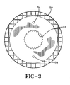
Fig. 2 is a sectional view of the assembled brake assembly ofFig. 1 as mounted and before the removal of shipping pins.Fig. 3 is an elevational view of a rotating disc. -
Fig. 4 is an elevational view of a stationary disc. -
Fig. 5 is an elevational view of the primary stationary disc. -
Fig. 6 is an elevational view of the spring retaining ring. -
Fig. 7 is a sectional view of the spring retaining ring taken substantially along line 7-7 ofFig. 6 . - A brake made in accordance with the present invention is indicated generally by the
numeral 10 in the drawings, the components of which are shown in the exploded viewFig. 1 .Brake 10 includes a housing, generally indicated by thenumeral 11 , which is preferably formed of cast iron and which is generally cylindrical in configuration having anopen end 12 and a closedend 13. When mounted on a vehicle, theopen end 12 ofhousing 11 is mounted flush against a vehicle frame (not shown), andhousing 11 is attached to the vehicle by a plurality of bolts (not shown). The bolts are inserted through holes in the vehicle frame and received in matching circumferentially spacedbores 14 formed inhousing 11. An o-ring 15 may be provided between the mating surfaces ofhousing 11 and the vehicle body, and a plurality of o-rings 16 may be provided around the bolts at the mating surfaces ofhousing 11 and the vehicle frame. -
Housing 11 further includes at least two circumferentially spacedpin holes 17, eachhole 17 being adapted to receive atorque pin 18. When mounted to a machine or vehicle,pin holes 17 are axially aligned with pin holes provided in the vehicle frame, thus securing thetorque pins 18 therebetween.Torque pins 18 are cylindrical in shape and are preferably made of steel. -
Housing 11 further includes acircumferential channel 20 located radially inward ofbores 14 and centered about anaxis 23. Channel 20 is adapted to receive anannular piston 21. Channel 20 serves as a piston housing, and to that end, whenannular piston 21 is so inserted, areservoir 22 is created. An input bore (not shown) communicates pressurized fluid from an external pressure source to thereservoir 22 thus selectively actuating thepiston 21. Because of the orientation of the ring shaped reservoir, a large surface area is created with which the pressurized fluid may act onannular piston 21. Further, because of the ring configuration, the actuatedpiston 21 exerts a substantially uniform load primarily along anaxis 23. -
Housing 11 further includes a plurality of shipping bolt bores 24 located on the closedend 13. Shipping bolt bores 24 are located radially inward ofbores 14 and are adapted to slidably receiveshipping bolts 25. As will hereinafter be described,bolts 25 maintain the components ofbrake 10 together during shipping and mounting to a vehicle. - When mounted to a vehicle or machine, the end of a shaft (not shown) projects into
housing 11 throughopen end 12. The shaft is coupled to the drive mechanism of the vehicle or machine, such that when a braking force is applied to the shaft, it is transmitted to the drive mechanism. A portion of the shaft located insidehousing 11 is splined, which allows for mounting to a plurality of rotatingdiscs 29, which are part of a disc brake assembly generally indicated bynumeral 30. Rotatingdiscs 29 are provided withsplines 31 on the radially inner surface, which are adapted to mesh with the shaft splines.Disc brake assembly 30 further includes a plurality ofstationary discs 32 which have a radially inner surface which fits over, but are not engaged by, the splined surface of the shaft. As best shown inFig. 1 ,stationary discs 32 androtatable discs 29 alternate to form a stack, which constitutesdisc brake assembly 30.Stationary discs 32 and rotatingdiscs 29 each include a pair ofdisc bores 34, each of which are adapted to slidably receive one of the plurality ofshipping bolts 25. It should be appreciated that the inclusion of just twobores 34 is exemplary, and any number of disc bores 34 may be provided. -
Disc brake assembly 30 further includes a primarystationary disc 33, which is located at the end of the disc stack proximate to theopen end 12 of thehousing 11. Primarystationary disc 33 has a radially inner surface which may fit over, but is not engaged by, the splined surface of the shaft. Primarystationary disc 33 includes a first pair of threadedholes 35 and a second pair of threadedholes 36. It should be appreciated that the inclusion of pairs ofholes discs housing 11 and first threadedholes 35 of the primarystationary disc 33 are axially aligned. Shippingbolts 25 are slidably received into housing bores 24 and disc bores 34 and the threaded portion ofshipping bolt 25 is received in first threaded holes 35. Thus, while in this orientation, shippingbolts 25 hold thedisc assembly 30 axially aligned. Further, in this orientation, thesplines 31 ofrotating discs 29 are aligned such that the during installation, the splined shaft easily slides into thedisc assembly 30. Also, theannular piston 21 anddisc assembly 30 are held inside thehousing 11 preventing disassembly of these elements. - The primary
stationary disc 33 andstationary discs 32 are each provided with at least one pair of diametricallyopposed ears 37 extending outwardly therefrom.Ears 37 include agroove 38, which receives one of the plurality of torque pins 18, which are fixedly positioned betweenhousing 11 and the vehicle frame when mounted. When mounted to a vehicle or machine, this orientation prevents rotation of thestationary discs 32 and primarystationary disc 33 relative torotating discs 30, while concurrently allowing them to slide axially alongaxis 23. -
Brake 10 further includes aspring retaining ring 40, which is generally a thin annular disc and includes a plurality of circumferentially spaced projections 41 (Figs. 6 and 7 ).Projections 41 are cylindrical and are each adapted to receive one of a plurality ofsprings 42.Spring retaining ring 40 further includes a plurality ofbores 43 which are adapted to slidably receive one of a plurality ofpin assemblies 44. It should be appreciated that while the drawings indicate only twospring assemblies 44, any number may be provided.Spring retaining ring 40 is oriented such thatprojections 41 extend toward primarystationary disc 33.Springs 42 are therefore located betweenspring retaining ring 40 and primarystationary disc 33. - Each
pin assembly 44 includes aspacer 45,screw 46 andwasher 47. Thespacer 45 is generally a hollow tube sized to slidably receivescrew 46. Thewasher 47 is positioned between thescrew head 48 andspacer 45.Screw 46 is received in the second pair of threadedholes 36 on primarystationary disc 33, thereby holding thespacer 45 andwasher 47 between thescrew head 48 and primarystationary disc 33.Spring retaining ring 40 is free to slide axially onspacer 45 between thewasher 47 and primarystationary disc 33. Prior to mounting on a vehicle or machine, the force of thesprings 42 maintainspring retaining ring 40 spaced from the primarystationary disc 33.Spring retaining ring 40 is free to slide axially alongspacer 45, and therefore, the force of thesprings 42 press thespring retaining ring 40 againstwasher 47.Springs 42 andspacer 45 are necessarily sized such that whenspring retaining ring 40 is contactingwasher 47, springs 42 remain under compression.Springs 42 are thus held in place betweenspring retaining ring 40 and primarystationary disc 33 and will not fall out during shipping or while mounting. -
Brake 10 thus has a pre-mounting orientation in that theshipping bolts 25 hold thedisc assembly 30 together and within thehousing 11. Further, thesprings 42 are held in place by thespring retaining ring 40, primarystationary disc 33 and thepin assembly 44. This orientation enablesbrake 10 to be easily mounted because the components stay assembled in a single unit during mounting. Further, rotatingdiscs 29 are prevented from rotating and held aligned by theshipping bolts 25 such that thesplines 31 of eachrotating disc 29 are aligned. This allows therotating discs 29 to easily slide onto the and couple with the shaft splines. - Once the
brake 10 is mounted to a shaft, theshipping bolts 25 are no longer necessary to keep thedisc assembly 30 together and may be removed. Once removed, rotatingdiscs 29 are free to rotate with the shaft. A plug (not shown) is inserted into bores 24 following the removal of theshipping bolts 25. - Further, the vehicle or machine is provided with bores which are sized to allow
pin assembly 44 to project therethrough when mounted. When mounted, thespring retaining ring 40 no longer rests againstwashers 47, but now rests against the vehicle body. As is evident fromFig. 2 , when mounted,spring retaining ring 40 is coplanar with theopen end 12 ofhousing 11. As mounted, thesprings 42 exert a spring force on the primarystationary disc 33, and because the rotating andstationary discs disc assembly 30. - As previously described,
piston 21 is positioned for movement withincircumferential channel 20 formed inhousing 11.Piston 21 includes anannular body portion 50, which is adapted to slide withincircumferential channel 20. Thebody portion 50 is provided with an annular radiallyexterior groove 51 a and an annular radiallyinterior groove 51b.Grooves seals seals piston 21 andcircumferential channel 20, so that a brake fluid, such as oil, is maintained withinreservoir 22. This oil communicates withreservoir 22 through the aforementioned input bore. -
Piston 21 is further provided with a plurality ofprojections 53 which project axially from the body portion and contact the primarystationary disc 33. In this manner,piston 21 bypasses rotating andstationary discs stationary disc 33. Whenpiston 21 is actuated,projections 53 push the primary stationary disc toward the vehicle body thereby compressing springs 42. - As mounted,
brake 10 applies a braking torque when no hydraulic fluid under pressure is supplied to the brake. This type of brake is commonly referred to as a failsafe brake, because its natural unactuated state prevents shaft rotation. Braking force is supplied by thesprings 42, which push primarystationary disc 33 away from the vehicle body. With no other axial forces present, springs 42 will clamp thedisc assembly 30 together between primarystationary disc 33 andhousing 11. In this condition, friction between therotating discs 29 and the stationary and primarystationary discs ears 37 are confined bytorque pins 18,stationary discs 32 and the primarystationary disc 33 will not rotate and a braking torque is applied to the shaft. This failsafe mechanism prevents unwanted and often times dangerous shaft movement. - When the vehicle or machine is turned on, hydraulic fluid may be supplied to the circumferential channel either automatically or by operator control. As the hydraulic fluid under pressure is received in the
circumferential channel 20, it acts onpiston 21 pushing it axially away from theclosed end 13 ofhousing 11.Projections 53 transfer the piston force to primarystationary disc 33, countering the force ofsprings 42. If sufficient pressure is supplied withincircumferential channel 20, the force ofpiston 21 will overcome the spring force, thereby moving primarystationary disc 33 axially towards the vehicle body to disengage the disc stack and allowing the free rotation ofrotatable discs 29. - In view of the foregoing, it should thus be evident that a brake as described herein accomplishes the objects of the present invention and otherwise substantially improves the art.
Claims (14)
- A brake (10) adapted to be carried by a rotatable shaft comprising a housing (11) having an open end (12); a plurality of stationary discs (32) in said housing; a plurality of rotatable discs (29) adapted to rotate with the shaft; said rotatable discs being positioned to be engaged by said stationary discs; a plurality of springs (42) biasing said stationary discs to engage said rotatable discs; a piston (21) movable to oppose the force of said springs; characterised in that said housing, said rotatable discs and said stationary discs each have at least one bore (24, 34); and a shipping bolt (25) received in each said bore, said bolts being removed after positioning the brake on the shaft to allow free rotation of said rotating discs.
- A brake according to claim 1 wherein said bolt (25) includes a threaded portion, one of said bores of said stationary discs (35) being provided with threads, said threads receiving said bolt threaded portion.
- A brake according to claim 1 wherein said open end (12) of said housing is adapted to be mounted to a vehicle body.
- A brake according to claim 1 wherein said rotating discs (29) include splines (31) on the radially interior portion, said splines are adapted to mesh with splines on the rotating shaft.
- A brake according to claim 4 wherein when said bolts (29) are received in said bores (24, 34), said splines of said rotating discs are aligned.
- A brake according to claim 1 wherein said piston (21) includes an annular body portion (50) and a plurality of projections (53), said piston being moveable by a pressurized fluid to cause said projections to apply a force to the stationary disc (32) which is proximate to said springs.
- A brake according to claim 6 wherein when no pressurized fluid is provided, saidsprings (42) cause said stationary discs (32) to engage said rotatable discs (29), applying a torque to the shaft.
- A brake according to a claim 1 wherein when said piston (21) is actuated and applies a force greater than the force of said springs (42), said stationary discs (32) and said rotatable discs (29) disengage.
- A brake according to claim 1, further comprising a plurality of pin assemblies (44), and a spring retaining ring (40) slidably mounted to said pin assemblies.
- A brake according to claim 9 wherein said pin assemblies (44) are carried by one of said stationary discs (32).
- A brake according to claim 10 wherein prior to positioning the brake (10) on the shaft, the force of said springs (42) maintains said spring retaining ring (40) spaced from said one of said stationary discs (32).
- A brake according to claim 11 wherein said pin assembly (44) includes a washer (47) which provides a stop for said spring retaining ring (40).
- A brake according to claim 9 wherein said pin assembly includes, a screw (46) and a spacer (45), said screw including a screw head (48) and wherein said spacer and said washer are held between said screw head and said stationary disc (32).
- A brake according to claim 9 wherein when said brake (10) is positioned on the shaft, said spring retaining ring (40) is adapted to interface with a vehicle body, wherein the body is provided with holes which are adapted to allow said pin assemblies (44) to reside therein.
Applications Claiming Priority (2)
| Application Number | Priority Date | Filing Date | Title |
|---|---|---|---|
| US11/210,285 US7353921B2 (en) | 2005-08-25 | 2005-08-25 | Self aligning brake kit |
| PCT/US2006/033128 WO2007025071A2 (en) | 2005-08-25 | 2006-08-23 | Pre-aligned brake disk stack for shipping and mounting facilitation |
Publications (3)
| Publication Number | Publication Date |
|---|---|
| EP1917450A2 EP1917450A2 (en) | 2008-05-07 |
| EP1917450A4 EP1917450A4 (en) | 2009-07-01 |
| EP1917450B1 true EP1917450B1 (en) | 2010-07-28 |
Family
ID=37772406
Family Applications (1)
| Application Number | Title | Priority Date | Filing Date |
|---|---|---|---|
| EP06802272A Not-in-force EP1917450B1 (en) | 2005-08-25 | 2006-08-23 | Self aligning brake kit |
Country Status (6)
| Country | Link |
|---|---|
| US (1) | US7353921B2 (en) |
| EP (1) | EP1917450B1 (en) |
| AT (1) | ATE475814T1 (en) |
| DE (1) | DE602006015817D1 (en) |
| ES (1) | ES2349134T3 (en) |
| WO (1) | WO2007025071A2 (en) |
Families Citing this family (7)
| Publication number | Priority date | Publication date | Assignee | Title |
|---|---|---|---|---|
| WO2007038693A2 (en) * | 2005-09-28 | 2007-04-05 | Baldwin Wilson Development Corporation | Disc brake assembly |
| US9068610B2 (en) * | 2012-12-11 | 2015-06-30 | Arvinmeritor Technology, Llc | Brake caliper assembly having a spacer tape and a method of manufacture |
| USD800198S1 (en) | 2016-01-21 | 2017-10-17 | Auburn Gear, Inc. | Combined electric motor and planetary transmission |
| USD783474S1 (en) * | 2016-04-28 | 2017-04-11 | Ausco Products, Inc. | Brake |
| US10174798B2 (en) * | 2016-05-18 | 2019-01-08 | Ausco Products, Inc. | Spring applied, hydraulically released wheel-mount brake having improved stationary disc support |
| US9915305B2 (en) * | 2016-06-08 | 2018-03-13 | Deere & Company | Retention pin having foot for holding spring in disc brake pack reaction plate during assembly and for operating stator disc |
| GB2575076B (en) * | 2018-06-28 | 2021-10-20 | Bamford Excavators Ltd | An actuation mechanism for a multi-plate brake |
Family Cites Families (12)
| Publication number | Priority date | Publication date | Assignee | Title |
|---|---|---|---|---|
| US3863038A (en) * | 1973-06-26 | 1975-01-28 | Lambert & Brake Corp | Disc brake |
| US4358001A (en) * | 1975-05-21 | 1982-11-09 | Iverson Roger A | Wet disc friction brake circulation system |
| US4368652A (en) * | 1978-04-27 | 1983-01-18 | Caterpillar Tractor Co. | Friction assemblies for use in planetary transmissions |
| FR2517003B1 (en) * | 1981-11-23 | 1985-12-27 | Soma Europ Transmissions | REDUCING WHEEL HUB AND INTEGRATED BRAKE |
| US4615418A (en) * | 1984-09-07 | 1986-10-07 | Atwell William L | Hydraulic safety brake |
| DE3900075A1 (en) * | 1989-01-03 | 1990-07-12 | Magyar Vagon Es Gepgyar | WHEEL HEAD FOR VEHICLES |
| US5389049A (en) * | 1992-03-05 | 1995-02-14 | Easom Engineering And Manufacturing Corp. | Pre-assembled disc stack having preset tolerance for use in drives, brakes and combinations thereof |
| US6089357A (en) * | 1997-09-30 | 2000-07-18 | Jackson; David C. | Dual piston swing brake system for cranes |
| US6145635A (en) * | 1998-06-23 | 2000-11-14 | White Hydraulics Inc. | Spring brake |
| US6405837B1 (en) * | 2000-02-10 | 2002-06-18 | Mico Incorporated | Combined parking and service brake |
| HU223863B1 (en) * | 2000-03-08 | 2005-02-28 | RÁBA Magyar Vagon- és Gépgyár Rt. | Hub for vehicle driven shaft |
| US6604613B2 (en) * | 2000-03-24 | 2003-08-12 | Performance Friction Corporation | Brake hub with floating rotor and mounting flange allowing simplified rotor removal and replacement |
-
2005
- 2005-08-25 US US11/210,285 patent/US7353921B2/en not_active Expired - Lifetime
-
2006
- 2006-08-23 AT AT06802272T patent/ATE475814T1/en not_active IP Right Cessation
- 2006-08-23 ES ES06802272T patent/ES2349134T3/en active Active
- 2006-08-23 WO PCT/US2006/033128 patent/WO2007025071A2/en not_active Ceased
- 2006-08-23 EP EP06802272A patent/EP1917450B1/en not_active Not-in-force
- 2006-08-23 DE DE602006015817T patent/DE602006015817D1/en active Active
Also Published As
| Publication number | Publication date |
|---|---|
| US20070045059A1 (en) | 2007-03-01 |
| ES2349134T3 (en) | 2010-12-28 |
| DE602006015817D1 (en) | 2010-09-09 |
| US7353921B2 (en) | 2008-04-08 |
| WO2007025071A3 (en) | 2007-11-08 |
| EP1917450A4 (en) | 2009-07-01 |
| ATE475814T1 (en) | 2010-08-15 |
| WO2007025071A2 (en) | 2007-03-01 |
| EP1917450A2 (en) | 2008-05-07 |
Similar Documents
| Publication | Publication Date | Title |
|---|---|---|
| EP2020524B1 (en) | Caliper brake system | |
| US7900752B2 (en) | Dual actuator friction brake assembly | |
| EP2932131B1 (en) | Disk brake with a parking brake, mechanical thrust assembly, and method of assembling | |
| EP0890037B1 (en) | Multi-disc brake actuator for vibration damping | |
| EP1255934B1 (en) | Combined parking and service brake | |
| EP0941419B1 (en) | Multi-disk brake actuator for vibration damping | |
| US3835961A (en) | Disk type brake | |
| US5133439A (en) | Fluid pressure actuated actuator mechanism for clutches and the like | |
| US4480531A (en) | Mechanical quick-release mechanism for spring-loaded brake cylinders | |
| US4328883A (en) | Hydraulic actuator mechanism for a friction clutch | |
| US7258208B1 (en) | Vertical mount disc brake with disc separator | |
| US4610331A (en) | Wheel hub with built-in brake | |
| US7353921B2 (en) | Self aligning brake kit | |
| US11846332B2 (en) | Open-ended, spring applied, hydraulically released brake with full alignment of components | |
| US6415896B1 (en) | Torque-receiving member and brake cylinder arrangement for drum brake | |
| EP2048402A1 (en) | Floating disc brake | |
| EP1801449B1 (en) | Ball ramp brake | |
| EP2450590A1 (en) | Caliper disc brake | |
| US10821827B1 (en) | Truck clutch conversion kit | |
| US7743893B2 (en) | Compact integrated brake system | |
| US8250967B2 (en) | Automatic transmission servo | |
| EP0495311A1 (en) | Brake actuator | |
| US4053036A (en) | Wheel brake assembly | |
| JPS5997330A (en) | Disc brake gear | |
| EP1565361B1 (en) | Compact integrated brake system |
Legal Events
| Date | Code | Title | Description |
|---|---|---|---|
| PUAI | Public reference made under article 153(3) epc to a published international application that has entered the european phase |
Free format text: ORIGINAL CODE: 0009012 |
|
| 17P | Request for examination filed |
Effective date: 20080305 |
|
| AK | Designated contracting states |
Kind code of ref document: A2 Designated state(s): AT BE BG CH CY CZ DE DK EE ES FI FR GB GR HU IE IS IT LI LT LU LV MC NL PL PT RO SE SI SK TR |
|
| AX | Request for extension of the european patent |
Extension state: AL BA HR MK RS |
|
| A4 | Supplementary search report drawn up and despatched |
Effective date: 20090603 |
|
| 17Q | First examination report despatched |
Effective date: 20090917 |
|
| GRAP | Despatch of communication of intention to grant a patent |
Free format text: ORIGINAL CODE: EPIDOSNIGR1 |
|
| DAX | Request for extension of the european patent (deleted) | ||
| GRAS | Grant fee paid |
Free format text: ORIGINAL CODE: EPIDOSNIGR3 |
|
| GRAA | (expected) grant |
Free format text: ORIGINAL CODE: 0009210 |
|
| AK | Designated contracting states |
Kind code of ref document: B1 Designated state(s): AT BE BG CH CY CZ DE DK EE ES FI FR GB GR HU IE IS IT LI LT LU LV MC NL PL PT RO SE SI SK TR |
|
| REG | Reference to a national code |
Ref country code: GB Ref legal event code: FG4D |
|
| REG | Reference to a national code |
Ref country code: CH Ref legal event code: EP |
|
| REG | Reference to a national code |
Ref country code: IE Ref legal event code: FG4D |
|
| REF | Corresponds to: |
Ref document number: 602006015817 Country of ref document: DE Date of ref document: 20100909 Kind code of ref document: P |
|
| REG | Reference to a national code |
Ref country code: SE Ref legal event code: TRGR |
|
| REG | Reference to a national code |
Ref country code: NL Ref legal event code: VDEP Effective date: 20100728 |
|
| LTIE | Lt: invalidation of european patent or patent extension |
Effective date: 20100728 |
|
| REG | Reference to a national code |
Ref country code: ES Ref legal event code: FG2A Effective date: 20101215 |
|
| PG25 | Lapsed in a contracting state [announced via postgrant information from national office to epo] |
Ref country code: LT Free format text: LAPSE BECAUSE OF FAILURE TO SUBMIT A TRANSLATION OF THE DESCRIPTION OR TO PAY THE FEE WITHIN THE PRESCRIBED TIME-LIMIT Effective date: 20100728 Ref country code: FI Free format text: LAPSE BECAUSE OF FAILURE TO SUBMIT A TRANSLATION OF THE DESCRIPTION OR TO PAY THE FEE WITHIN THE PRESCRIBED TIME-LIMIT Effective date: 20100728 Ref country code: AT Free format text: LAPSE BECAUSE OF FAILURE TO SUBMIT A TRANSLATION OF THE DESCRIPTION OR TO PAY THE FEE WITHIN THE PRESCRIBED TIME-LIMIT Effective date: 20100728 Ref country code: NL Free format text: LAPSE BECAUSE OF FAILURE TO SUBMIT A TRANSLATION OF THE DESCRIPTION OR TO PAY THE FEE WITHIN THE PRESCRIBED TIME-LIMIT Effective date: 20100728 |
|
| PG25 | Lapsed in a contracting state [announced via postgrant information from national office to epo] |
Ref country code: PL Free format text: LAPSE BECAUSE OF FAILURE TO SUBMIT A TRANSLATION OF THE DESCRIPTION OR TO PAY THE FEE WITHIN THE PRESCRIBED TIME-LIMIT Effective date: 20100728 Ref country code: SI Free format text: LAPSE BECAUSE OF FAILURE TO SUBMIT A TRANSLATION OF THE DESCRIPTION OR TO PAY THE FEE WITHIN THE PRESCRIBED TIME-LIMIT Effective date: 20100728 Ref country code: PT Free format text: LAPSE BECAUSE OF FAILURE TO SUBMIT A TRANSLATION OF THE DESCRIPTION OR TO PAY THE FEE WITHIN THE PRESCRIBED TIME-LIMIT Effective date: 20101129 Ref country code: BG Free format text: LAPSE BECAUSE OF FAILURE TO SUBMIT A TRANSLATION OF THE DESCRIPTION OR TO PAY THE FEE WITHIN THE PRESCRIBED TIME-LIMIT Effective date: 20101028 Ref country code: IS Free format text: LAPSE BECAUSE OF FAILURE TO SUBMIT A TRANSLATION OF THE DESCRIPTION OR TO PAY THE FEE WITHIN THE PRESCRIBED TIME-LIMIT Effective date: 20101128 Ref country code: CY Free format text: LAPSE BECAUSE OF FAILURE TO SUBMIT A TRANSLATION OF THE DESCRIPTION OR TO PAY THE FEE WITHIN THE PRESCRIBED TIME-LIMIT Effective date: 20100728 |
|
| PG25 | Lapsed in a contracting state [announced via postgrant information from national office to epo] |
Ref country code: GR Free format text: LAPSE BECAUSE OF FAILURE TO SUBMIT A TRANSLATION OF THE DESCRIPTION OR TO PAY THE FEE WITHIN THE PRESCRIBED TIME-LIMIT Effective date: 20101029 Ref country code: MC Free format text: LAPSE BECAUSE OF NON-PAYMENT OF DUE FEES Effective date: 20100831 Ref country code: LV Free format text: LAPSE BECAUSE OF FAILURE TO SUBMIT A TRANSLATION OF THE DESCRIPTION OR TO PAY THE FEE WITHIN THE PRESCRIBED TIME-LIMIT Effective date: 20100728 |
|
| REG | Reference to a national code |
Ref country code: CH Ref legal event code: PL |
|
| PG25 | Lapsed in a contracting state [announced via postgrant information from national office to epo] |
Ref country code: LI Free format text: LAPSE BECAUSE OF NON-PAYMENT OF DUE FEES Effective date: 20100831 Ref country code: DK Free format text: LAPSE BECAUSE OF FAILURE TO SUBMIT A TRANSLATION OF THE DESCRIPTION OR TO PAY THE FEE WITHIN THE PRESCRIBED TIME-LIMIT Effective date: 20100728 Ref country code: CH Free format text: LAPSE BECAUSE OF NON-PAYMENT OF DUE FEES Effective date: 20100831 |
|
| PG25 | Lapsed in a contracting state [announced via postgrant information from national office to epo] |
Ref country code: EE Free format text: LAPSE BECAUSE OF FAILURE TO SUBMIT A TRANSLATION OF THE DESCRIPTION OR TO PAY THE FEE WITHIN THE PRESCRIBED TIME-LIMIT Effective date: 20100728 Ref country code: CZ Free format text: LAPSE BECAUSE OF FAILURE TO SUBMIT A TRANSLATION OF THE DESCRIPTION OR TO PAY THE FEE WITHIN THE PRESCRIBED TIME-LIMIT Effective date: 20100728 Ref country code: SK Free format text: LAPSE BECAUSE OF FAILURE TO SUBMIT A TRANSLATION OF THE DESCRIPTION OR TO PAY THE FEE WITHIN THE PRESCRIBED TIME-LIMIT Effective date: 20100728 Ref country code: RO Free format text: LAPSE BECAUSE OF FAILURE TO SUBMIT A TRANSLATION OF THE DESCRIPTION OR TO PAY THE FEE WITHIN THE PRESCRIBED TIME-LIMIT Effective date: 20100728 |
|
| PLBE | No opposition filed within time limit |
Free format text: ORIGINAL CODE: 0009261 |
|
| STAA | Information on the status of an ep patent application or granted ep patent |
Free format text: STATUS: NO OPPOSITION FILED WITHIN TIME LIMIT |
|
| 26N | No opposition filed |
Effective date: 20110429 |
|
| PG25 | Lapsed in a contracting state [announced via postgrant information from national office to epo] |
Ref country code: IE Free format text: LAPSE BECAUSE OF NON-PAYMENT OF DUE FEES Effective date: 20100823 |
|
| REG | Reference to a national code |
Ref country code: DE Ref legal event code: R097 Ref document number: 602006015817 Country of ref document: DE Effective date: 20110429 |
|
| PG25 | Lapsed in a contracting state [announced via postgrant information from national office to epo] |
Ref country code: LU Free format text: LAPSE BECAUSE OF NON-PAYMENT OF DUE FEES Effective date: 20100823 Ref country code: HU Free format text: LAPSE BECAUSE OF FAILURE TO SUBMIT A TRANSLATION OF THE DESCRIPTION OR TO PAY THE FEE WITHIN THE PRESCRIBED TIME-LIMIT Effective date: 20110129 |
|
| PG25 | Lapsed in a contracting state [announced via postgrant information from national office to epo] |
Ref country code: TR Free format text: LAPSE BECAUSE OF FAILURE TO SUBMIT A TRANSLATION OF THE DESCRIPTION OR TO PAY THE FEE WITHIN THE PRESCRIBED TIME-LIMIT Effective date: 20100728 |
|
| REG | Reference to a national code |
Ref country code: FR Ref legal event code: PLFP Year of fee payment: 11 |
|
| REG | Reference to a national code |
Ref country code: FR Ref legal event code: PLFP Year of fee payment: 12 |
|
| REG | Reference to a national code |
Ref country code: FR Ref legal event code: PLFP Year of fee payment: 13 |
|
| PGFP | Annual fee paid to national office [announced via postgrant information from national office to epo] |
Ref country code: ES Payment date: 20200901 Year of fee payment: 15 Ref country code: GB Payment date: 20200813 Year of fee payment: 15 Ref country code: FR Payment date: 20200715 Year of fee payment: 15 Ref country code: DE Payment date: 20200812 Year of fee payment: 15 |
|
| PGFP | Annual fee paid to national office [announced via postgrant information from national office to epo] |
Ref country code: IT Payment date: 20200713 Year of fee payment: 15 Ref country code: BE Payment date: 20200715 Year of fee payment: 15 Ref country code: SE Payment date: 20200811 Year of fee payment: 15 |
|
| REG | Reference to a national code |
Ref country code: DE Ref legal event code: R119 Ref document number: 602006015817 Country of ref document: DE |
|
| REG | Reference to a national code |
Ref country code: SE Ref legal event code: EUG |
|
| REG | Reference to a national code |
Ref country code: BE Ref legal event code: MM Effective date: 20210831 |
|
| GBPC | Gb: european patent ceased through non-payment of renewal fee |
Effective date: 20210823 |
|
| PG25 | Lapsed in a contracting state [announced via postgrant information from national office to epo] |
Ref country code: SE Free format text: LAPSE BECAUSE OF NON-PAYMENT OF DUE FEES Effective date: 20210824 |
|
| PG25 | Lapsed in a contracting state [announced via postgrant information from national office to epo] |
Ref country code: IT Free format text: LAPSE BECAUSE OF NON-PAYMENT OF DUE FEES Effective date: 20210823 Ref country code: GB Free format text: LAPSE BECAUSE OF NON-PAYMENT OF DUE FEES Effective date: 20210823 Ref country code: FR Free format text: LAPSE BECAUSE OF NON-PAYMENT OF DUE FEES Effective date: 20210831 Ref country code: DE Free format text: LAPSE BECAUSE OF NON-PAYMENT OF DUE FEES Effective date: 20220301 Ref country code: BE Free format text: LAPSE BECAUSE OF NON-PAYMENT OF DUE FEES Effective date: 20210831 |
|
| REG | Reference to a national code |
Ref country code: ES Ref legal event code: FD2A Effective date: 20221003 |
|
| PG25 | Lapsed in a contracting state [announced via postgrant information from national office to epo] |
Ref country code: ES Free format text: LAPSE BECAUSE OF NON-PAYMENT OF DUE FEES Effective date: 20210824 |