EP1916846A1 - Device and method for monitoring vehicle surroundings - Google Patents
Device and method for monitoring vehicle surroundings Download PDFInfo
- Publication number
- EP1916846A1 EP1916846A1 EP06781992A EP06781992A EP1916846A1 EP 1916846 A1 EP1916846 A1 EP 1916846A1 EP 06781992 A EP06781992 A EP 06781992A EP 06781992 A EP06781992 A EP 06781992A EP 1916846 A1 EP1916846 A1 EP 1916846A1
- Authority
- EP
- European Patent Office
- Prior art keywords
- image
- obstacle
- vehicle
- obstacle detection
- camera
- Prior art date
- Legal status (The legal status is an assumption and is not a legal conclusion. Google has not performed a legal analysis and makes no representation as to the accuracy of the status listed.)
- Granted
Links
Images






Classifications
-
- B—PERFORMING OPERATIONS; TRANSPORTING
- B60—VEHICLES IN GENERAL
- B60R—VEHICLES, VEHICLE FITTINGS, OR VEHICLE PARTS, NOT OTHERWISE PROVIDED FOR
- B60R1/00—Optical viewing arrangements; Real-time viewing arrangements for drivers or passengers using optical image capturing systems, e.g. cameras or video systems specially adapted for use in or on vehicles
- B60R1/20—Real-time viewing arrangements for drivers or passengers using optical image capturing systems, e.g. cameras or video systems specially adapted for use in or on vehicles
- B60R1/22—Real-time viewing arrangements for drivers or passengers using optical image capturing systems, e.g. cameras or video systems specially adapted for use in or on vehicles for viewing an area outside the vehicle, e.g. the exterior of the vehicle
- B60R1/23—Real-time viewing arrangements for drivers or passengers using optical image capturing systems, e.g. cameras or video systems specially adapted for use in or on vehicles for viewing an area outside the vehicle, e.g. the exterior of the vehicle with a predetermined field of view
- B60R1/27—Real-time viewing arrangements for drivers or passengers using optical image capturing systems, e.g. cameras or video systems specially adapted for use in or on vehicles for viewing an area outside the vehicle, e.g. the exterior of the vehicle with a predetermined field of view providing all-round vision, e.g. using omnidirectional cameras
-
- B—PERFORMING OPERATIONS; TRANSPORTING
- B60—VEHICLES IN GENERAL
- B60R—VEHICLES, VEHICLE FITTINGS, OR VEHICLE PARTS, NOT OTHERWISE PROVIDED FOR
- B60R11/00—Arrangements for holding or mounting articles, not otherwise provided for
- B60R11/04—Mounting of cameras operative during drive; Arrangement of controls thereof relative to the vehicle
-
- B—PERFORMING OPERATIONS; TRANSPORTING
- B60—VEHICLES IN GENERAL
- B60R—VEHICLES, VEHICLE FITTINGS, OR VEHICLE PARTS, NOT OTHERWISE PROVIDED FOR
- B60R19/00—Wheel guards; Radiator guards, e.g. grilles; Obstruction removers; Fittings damping bouncing force in collisions
- B60R19/02—Bumpers, i.e. impact receiving or absorbing members for protecting vehicles or fending off blows from other vehicles or objects
- B60R19/48—Bumpers, i.e. impact receiving or absorbing members for protecting vehicles or fending off blows from other vehicles or objects combined with, or convertible into, other devices or objects, e.g. bumpers combined with road brushes, bumpers convertible into beds
- B60R19/483—Bumpers, i.e. impact receiving or absorbing members for protecting vehicles or fending off blows from other vehicles or objects combined with, or convertible into, other devices or objects, e.g. bumpers combined with road brushes, bumpers convertible into beds with obstacle sensors of electric or electronic type
-
- B—PERFORMING OPERATIONS; TRANSPORTING
- B60—VEHICLES IN GENERAL
- B60R—VEHICLES, VEHICLE FITTINGS, OR VEHICLE PARTS, NOT OTHERWISE PROVIDED FOR
- B60R2300/00—Details of viewing arrangements using cameras and displays, specially adapted for use in a vehicle
- B60R2300/10—Details of viewing arrangements using cameras and displays, specially adapted for use in a vehicle characterised by the type of camera system used
- B60R2300/102—Details of viewing arrangements using cameras and displays, specially adapted for use in a vehicle characterised by the type of camera system used using 360 degree surveillance camera system
-
- B—PERFORMING OPERATIONS; TRANSPORTING
- B60—VEHICLES IN GENERAL
- B60R—VEHICLES, VEHICLE FITTINGS, OR VEHICLE PARTS, NOT OTHERWISE PROVIDED FOR
- B60R2300/00—Details of viewing arrangements using cameras and displays, specially adapted for use in a vehicle
- B60R2300/10—Details of viewing arrangements using cameras and displays, specially adapted for use in a vehicle characterised by the type of camera system used
- B60R2300/105—Details of viewing arrangements using cameras and displays, specially adapted for use in a vehicle characterised by the type of camera system used using multiple cameras
-
- B—PERFORMING OPERATIONS; TRANSPORTING
- B60—VEHICLES IN GENERAL
- B60R—VEHICLES, VEHICLE FITTINGS, OR VEHICLE PARTS, NOT OTHERWISE PROVIDED FOR
- B60R2300/00—Details of viewing arrangements using cameras and displays, specially adapted for use in a vehicle
- B60R2300/30—Details of viewing arrangements using cameras and displays, specially adapted for use in a vehicle characterised by the type of image processing
- B60R2300/301—Details of viewing arrangements using cameras and displays, specially adapted for use in a vehicle characterised by the type of image processing combining image information with other obstacle sensor information, e.g. using RADAR/LIDAR/SONAR sensors for estimating risk of collision
-
- B—PERFORMING OPERATIONS; TRANSPORTING
- B60—VEHICLES IN GENERAL
- B60R—VEHICLES, VEHICLE FITTINGS, OR VEHICLE PARTS, NOT OTHERWISE PROVIDED FOR
- B60R2300/00—Details of viewing arrangements using cameras and displays, specially adapted for use in a vehicle
- B60R2300/30—Details of viewing arrangements using cameras and displays, specially adapted for use in a vehicle characterised by the type of image processing
- B60R2300/304—Details of viewing arrangements using cameras and displays, specially adapted for use in a vehicle characterised by the type of image processing using merged images, e.g. merging camera image with stored images
- B60R2300/305—Details of viewing arrangements using cameras and displays, specially adapted for use in a vehicle characterised by the type of image processing using merged images, e.g. merging camera image with stored images merging camera image with lines or icons
-
- B—PERFORMING OPERATIONS; TRANSPORTING
- B60—VEHICLES IN GENERAL
- B60R—VEHICLES, VEHICLE FITTINGS, OR VEHICLE PARTS, NOT OTHERWISE PROVIDED FOR
- B60R2300/00—Details of viewing arrangements using cameras and displays, specially adapted for use in a vehicle
- B60R2300/60—Details of viewing arrangements using cameras and displays, specially adapted for use in a vehicle characterised by monitoring and displaying vehicle exterior scenes from a transformed perspective
- B60R2300/607—Details of viewing arrangements using cameras and displays, specially adapted for use in a vehicle characterised by monitoring and displaying vehicle exterior scenes from a transformed perspective from a bird's eye viewpoint
-
- B—PERFORMING OPERATIONS; TRANSPORTING
- B60—VEHICLES IN GENERAL
- B60R—VEHICLES, VEHICLE FITTINGS, OR VEHICLE PARTS, NOT OTHERWISE PROVIDED FOR
- B60R2300/00—Details of viewing arrangements using cameras and displays, specially adapted for use in a vehicle
- B60R2300/70—Details of viewing arrangements using cameras and displays, specially adapted for use in a vehicle characterised by an event-triggered choice to display a specific image among a selection of captured images
-
- B—PERFORMING OPERATIONS; TRANSPORTING
- B60—VEHICLES IN GENERAL
- B60R—VEHICLES, VEHICLE FITTINGS, OR VEHICLE PARTS, NOT OTHERWISE PROVIDED FOR
- B60R2300/00—Details of viewing arrangements using cameras and displays, specially adapted for use in a vehicle
- B60R2300/80—Details of viewing arrangements using cameras and displays, specially adapted for use in a vehicle characterised by the intended use of the viewing arrangement
- B60R2300/806—Details of viewing arrangements using cameras and displays, specially adapted for use in a vehicle characterised by the intended use of the viewing arrangement for aiding parking
-
- B—PERFORMING OPERATIONS; TRANSPORTING
- B60—VEHICLES IN GENERAL
- B60R—VEHICLES, VEHICLE FITTINGS, OR VEHICLE PARTS, NOT OTHERWISE PROVIDED FOR
- B60R2300/00—Details of viewing arrangements using cameras and displays, specially adapted for use in a vehicle
- B60R2300/80—Details of viewing arrangements using cameras and displays, specially adapted for use in a vehicle characterised by the intended use of the viewing arrangement
- B60R2300/8093—Details of viewing arrangements using cameras and displays, specially adapted for use in a vehicle characterised by the intended use of the viewing arrangement for obstacle warning
Definitions
- the present invention relates to a device and a method for monitoring vehicle surroundings, which enable a driver to recognize obstacles or the like present around a vehicle.
- An example is a rear-view camera device which arranges a camera in a car body rear part such as a rear trunk part, and displays a camera video imaged by the camera with a vehicle rear part set as an imaging direction on a display monitor of a dashboard to be viewed by the driver.
- this rear-view camera device there has been available a type which overlay-displays a predicted track in a camera video according to steering angles of own vehicle front wheels so that a positional relation between a traveling direction of the own vehicle and an obstacle can be easily determined by the camera video.
- a device which uses an image synthesis technology to display a bird's-eye image looking down on an own vehicle from a virtual camera above the own vehicle, and displays a virtual object in a detection range of an obstacle detection sensor, a safe area having no obstacle according to a distance to an obstacle, or a road surface boundary of the object in this bird's-eye image.
- a warning sound is issued when the obstacle is detected by the obstacle detection sensor.
- the bird's-eye image is displayed by combining the detection range of the obstacle detection sensor with the bird's-eye image, and the warning is simultaneously given, if the obstacle detected by the obstacle detection sensor is present in space away from a ground surface, irrespective of actual presence of the obstacle within the detection range of the obstacle detection sensor, the obstacle is displayed in a manner of not being present within the detection range of the obstacle detection sensor in the bird's-eye image, giving uncomfortable feelings.
- the present invention has been proposed with the aforementioned situation in mind, and objects of the invention are to provide a device and a method for monitoring vehicle surroundings, which display, when an obstacle detection range is displayed in a view point converted image, the obstacle detection range without giving any uncomfortable feelings in a positional relation between the obstacle detection range and an obstacle.
- a vehicle surrounding monitoring device of the present invention includes at least one camera installed in an own vehicle to image a video around the own vehicle, obstacle detection means installed in the own vehicle to detect an obstacle in an obstacle detection area, image processing means for converting a camera image imaged by the camera into a view point converted image seen from a virtual view point above the own vehicle, and display means for displaying the view point conversion image converted by the image processing means.
- a warning is given by a warning sound upon entry of an obstacle within an obstacle detection range of the obstacle detection means, and simultaneously the image processing means combines an image of the obstacle detection range of the obstacle detection means with an obstacle image which is imaged by the camera and included in the view point converted image so that the both images are to be in contact.
- a vehicle surrounding monitoring method includes imaging a video around an own vehicle by a camera installed in the own vehicle, detecting an obstacle within an imaging range of the camera, and to solve the aforementioned problem, when presence of an obstacle is detected, giving a warning by a warning sound upon entry of the obstacle within an obstacle detection range of obstacle detection means, and simultaneously synthesizing an image of the obstacle detection range of the obstacle detection means to be in contact with an obstacle imaged by the camera and included in a view point converted image.
- the present invention is applied to a vehicle surrounding monitoring device configured, for example, as shown in FIG. 1 .
- a vehicle surrounding monitoring device configured, for example, as shown in FIG. 1 .
- at least one or more cameras 2-1, 2-2, ..., 2-N (simply referred to as “camera 2" generically hereinafter), a plurality of obstacle detection sensors (obstacle detection means) 3-1, 3-2, ..., 3-N (simply referred to as "obstacle sensor 3" generically hereinafter), and a display device 4 are connected to an image processing unit (image processing means) 1.
- the cameras 2-1, 2-2, ..., 2-N are arranged in different positions of an own vehicle, and imaging directions are different from one another.
- the obstacle sensors 3-1, 3-2, ..., 3-3 are arranged in different positions of the own vehicle, and obstacle detection ranges are different from one another.
- the cameras 2-1, 2-2, ..., 2-N are, for example, super-wide-angle cameras where horizontal field angles are 180°, and include four cameras, i.e., a camera 2F for imaging a front side of the vehicle, a camera 2B for imaging a rear side, a camera 2R for imaging a right side, and a camera 2L for imaging a left side.
- the cameras 2F, 2B, 2R, and 2L include, by the image processing unit 1 described below, as in the case of a bird's-eye image (view point converted image) 100 subjected to image synthesis processing (view point conversion processing) to be displayed by the display unit 4 shown in FIG. 3 , a front camera display area 101F, a rear camera display area 101B, a right camera display area 101R, and a left camera display area 101L, and can form images for understanding all the surroundings of the own vehicle.
- the bird's-eye image 100 is an image subjected to view point conversion processing as if to look down the own vehicle from above by using camera image data imaged by the cameras 2F, 2B, 2R, and 2L shown in FIG. 2 .
- An image drawn roughly in the center of the bird's-eye image is an own vehicle overlay image 102 having a size corresponding to a floor area of the own vehicle stored beforehand in an overlay image storage unit which is not shown.
- Black beltlike partition lines are arranged between the display areas of the bird's-eye image 100. Note that each display area can be allocated differently from the example according to an actual imaging area.
- the obstacle sensors 3-1, 3-2, ..., 3-3 ranges (obstacle detection ranges) provided with widths of angle of about 90° to 140° from installation positions in fan shapes to detect obstacles present in a distance of about 1 m from the own vehicle are set.
- the obstacle sensors 3-1, 3-2, ..., 3-3 include four obstacle sensors, i.e., an obstacle sensor 3FR for detecting obstacles of front right direction, an obstacle sensor 3FL for detecting obstacles of front left direction, an obstacle sensor 3BR for detecting obstacles of rear right direction, and an obstacle sensor 3BL for detecting obstacles of rear left direction.
- These obstacle sensors 3FR, 3FL, 3BR, and 3BL are configured so that in FIG.
- obstacles present in a front camera display area 101F can be detected by the obstacle sensors 3FR and 3FL
- obstacles present in a rear camera display area 101B can be detected by the obstacle sensors 3BR and 3BL
- obstacles present in a right camera display area 101R can be detected by the obstacle sensors 3FR and 3BR
- obstacles present in a left camera display area 101L can be detected by the obstacle sensors 3FL and 3BL.
- the cameras 2-1, 2-2, ..., 2-N consist of cameras 2F, 2B, 2R, and 2L respectively
- the obstacle sensors 3-1, 3-2, ,..., 3-3 consist of obstacle sensors 3FR, 3FL, 3BR, and 3BL respectively
- the image processing unit 1 enters camera image data of the vehicle surroundings imaged by the cameras 2F, 2B, 2R, and 2L to frame buffers 11-1, 11-2, ..., 11-N (simply referred to as "frame buffer 11" generically hereinafter) which are input buffers corresponding to the cameras 2F, 2B, 2R, and 2L to temporarily store the data.
- a plurality of camera image data stored in the frame buffer 11 are used for forming a bird's-eye image 100 by image synthesis processing of a pixel synthesis unit 13.
- the image processing unit 1 enters sensor signals from the obstacle sensors 3FR, 3FL, 3BR, and 3BL to a single obstacle determination unit 12.
- the obstacle determination unit 12 calculates presence of an obstacle around the own vehicle, and a position and a distance when an obstacle is present based on each entered sensor signal.
- the obstacle determination unit 12 outputs the calculated presence of the obstacle, and the calculated position and distance of the obstacle to a table switching unit 14.
- the table switching unit 14 switches a table (address conversion table) to be referred to in the image synthesis processing of the pixel synthesis unit 13 to one of a plurality of address conversion tables among the plurality of address conversion tables stored in a table storage unit 15.
- each pixel of the bird's-eye image 100 which is an output image output to the display device 4 and information for specifying image data to be stored in the pixel is described. Specifically, in the address conversion table, whether to store camera image data in each pixel of the bird's-eye image 100 which is the output image, whether to store an overlay image indicating the own vehicle or the obstacle, which of addresses in which of the frame buffers 11 image data is taken out from when the camera image data is stored, and which of pieces of color information is stored when the overlay image is stored are described.
- the pixel synthesis unit 13 refers to the address conversion table selected by the video signal generation unit 16 to take out the camera image data stored in the frame buffer 11 or the overlay image indicating the own vehicle or the obstacle, and stores the image in the output buffer of the video signal generation unit 16. Accordingly, the pixel synthesis unit 13 stores the bird's-eye image 100 obtained by synthesizing the plurality of camera image data imaged by the cameras 2F, 2B, 2R, and 2L in the video signal generation unit 16.
- the video signal generation unit 16 Upon storage of the bird's-eye image 100 of one frame in the output buffer by the pixel synthesis unit 13, the video signal generation unit 16 outputs the bird's-eye image 100 to the display device 4 to display the image therein. Output timing of the bird's-eye image 100 from the output buffer of the video signal generation unit 16 to the display device 4 has been preset in advance together with timing of the image synthesis processing of the pixel synthesis unit 13.
- This warning output unit 17 includes a speaker for outputting a predetermined warning sound to the driver.
- the bird's-eye image 100 when a pole 110 is present as an obstacle in a rear right side of the own vehicle, the bird's-eye image 100 includes, as shown in FIG. 4C , an obstacle image 120 in the rear camera display area 101B below a right side of the own vehicle overlay image 102.
- the pole 110 when the obstacle stands vertically in contact with the ground surface, in the bird's-eye image 100, a contact surface between the pole 110 and the ground surface can be displayed in a correct position with respect to the own vehicle.
- the image processing unit 1 forms an obstacle image 120' where the pole 110 of the rear camera display area 101B is displayed to be distorted so that the obstacle image 120' can be displayed in contact with the own vehicle overlay image 102.
- an obstacle present in a position closest to the own vehicle is a bumper of the other vehicle 130, and present at a predetermined height from the ground surface different from the pole 110.
- the phenomenon of the shifting of the positional relation between the own vehicle and the other vehicle 130 in the bird's-eye image 100 is caused, as shown in FIG. 8 , by a principle of generating a bird's-eye image 100 itself where depending on a relation between a ground height H1 of the camera 2 and a ground height H2 of the obstacle, as for the obstacle above the ground, a distance from the camera 2 to the obstacle is imaged as if the obstacle is present in a position more away from the camera 2 than that in an actual case.
- the obstacle is imaged at a distance D2 within a camera imaging range, and thus the bird's-eye image 100 includes the obstacle in the position of the distance D2 greater than the distance D1.
- the obstacle detection range 3a imaged by the camera 2 includes, as shown in FIG. 10 , not only an area 3b where the obstacle detection range 3a is projected on the ground surface but also an area 3c of a range passed from the installation position of the camera 2 through an end of the obstacle detection range 3a and projected on the ground surface.
- the image of the obstacle detection range 3a of the obstacle sensor 3 is, as shown in FIG. 10 , an overlay image (referred to as obstacle detection range image hereinafter) indicating the area 3c of a range where the obstacle detection range 3a is projected on the ground surface with the attaching position of the camera 2 set as a view point when the obstacle detection range 3a is imaged by the camera 2.
- obstacle detection range image an overlay image indicating the area 3c of a range where the obstacle detection range 3a is projected on the ground surface with the attaching position of the camera 2 set as a view point when the obstacle detection range 3a is imaged by the camera 2.
- Such a vehicle surrounding monitoring device directly displays the bird's-eye image 100 processed by the pixel synthesis unit 13 at a normal time when the obstacle determination unit 12 detects no obstacle, and synthesizes an obstacle detection range image with the bird's-eye image 100 to display it thereon when the obstacle determination unit 12 detects an obstacle. Accordingly, in the vehicle surrounding monitoring device, upon detection of the obstacle, if the obstacle is present above and thus not in contact with the ground surface, presence of the obstacle within the obstacle detection range 3a of the obstacle sensor 3 is recognized in the bird's-eye image 100 subjected to the view point conversion.
- the bird's-eye image 100 shown in FIGS. 11A and 11B is switched to displaying shown in any one of FIGS. 12 to 14 .
- the obstacle determination unit 12 detects no more obstacle, the displaying is returned to the bird's-eye image 100 of FIGS. 11A and 11B .
- a bird's eye image 100 shown in FIG. 12 is an image obtained by displaying an other vehicle image 140 which is an obstacle detected in the rear right side of the own vehicle in the rear camera display area 101B, and synthesizing semi-transparently an obstacle detection range image 151 indicating an area 3c of a range passed from the installation position of the camera 2 through the end of the obstacle detection range 3a and projected on the ground surface with a predetermined area in the rear side of the own vehicle.
- the obstacle determination unit 12 notifies the detection of the obstacle in the rear right side of the own vehicle to the table switching unit 14.
- the table switching unit 14 selects an address conversion table to display the obstacle detection range image 151 in a rear side of the own vehicle overlay image 102.
- the pixel synthesis unit 13 can form a bird's-eye image 100 where not the camera image data but the obstacle detection range image 151 is displayed in the rear side of the own vehicle overlay image 102.
- the obstacle determination unit 12 operates the warning output unit 17 to give a warning about presence of the other vehicle 130 within the obstacle detection range 3a.
- a bird's-eye image 100 shown in FIG. 13 is an image obtained by synthesizing a steric obstacle detection range image 152 with the obstacle detection range 3a of the obstacle sensor 3BR which has detected the other vehicle 130.
- This obstacle detection range image 152 is configured by setting an area a (area 3b of FIG. 10 ) where the obstacle detection range 3a is projected on the ground surface seen from above as a bottom surface, and connecting planes b and c corresponding to the area 3c shown in FIG. 10 to the area a of the bottom surface.
- These planes b and c are planes extending vertically from a boundary of the area where the obstacle detection range 3a of the obstacle sensor 3 is projected on the ground surface with the attaching position of the camera 2 as a view point.
- An end point d of the obstacle detection range image 152 is, as shown in FIG. 10 , a point passed from the installation position of the camera 2 through one upper end part of the obstacle detection range 3a and projected on the ground surface.
- An end point e of the obstacle detection range image 152 is, as shown in FIG. 10 , a point passed from the installation position of the camera 2 through the other upper end part of the obstacle detection range 3a and projected on the ground surface.
- the table switching unit 14 selects an address conversion table for displaying the steric obstacle detection range image 152 in the rear side of the own vehicle overlay image 102.
- Steric surfaces b and c of the steric obstacle detection range image 152 are preferably displayed by different colors to facilitate differentiation of the steric surfaces b and c from each other.
- the steric obstacle detection range image 152 as the image of the obstacle detection range 3a, presence of the other vehicle 130 within the obstacle detection range 3a of the obstacle sensor 3 in its separated state from the ground surface can be presented.
- a bird's-eye image 100 shown in FIG. 14 is an image obtained by synthesizing a guide line 153 in a position where the other vehicle image 140 present away from and above the ground surface is projected on the ground surface with the obstacle detection range image 150 of the area (area 3b of FIG. 10 ) where the obstacle detection range 3a is projected on the ground surface.
- the guide line 153 is a line where a car body part and a bumper part as ends of the other vehicle 130 are projected on the ground surface, and displayed in contact with the obstacle detection range image 150.
- the table switching unit 14 selects an address conversion table for displaying the obstacle detection range image 150 in the rear side of the own vehicle overlay image 102.
- the pixel synthesis unit 13 forms a bird's-eye image 100 by synthesizing the guide line 153 with a position of a distance calculated by the obstacle determination unit 12 where a part of the other vehicle 130 away from the ground surface is present.
- the pixel synthesis unit 13 prestores distance coordinates from the obstacle sensor 3 in the bird's-eye image 100, and synthesizes the guide line 153 with the position of the distance to the other vehicle 130 calculated by the obstacle determination unit 12 in the bird's-eye image 100. Accordingly, the guide line 153 is displayed in a form where the other vehicle image 140 is projected on the ground surface.
- the guide line 153 is synthesized with the bird's-eye image 100 in a form of being stacked on the obstacle detection range image 150, whereby the presence of the other vehicle 130 within the obstacle detection range 3a can be presented to the driver.
- the display form of the own vehicle overlay image 102 drawn roughly in the center of the bird's-eye image 100 may be changed.
- the other vehicle image 140 is displayed in a rear right side, overlay images 160A and 160B are formed in left and right sides of the own vehicle overlay image 102, and the overlay image 160B in a direction where the other vehicle image 140 is present is displayed by a warning color.
- the table switching unit 14 selects an address conversion table for displaying respectively the semitransparent overlay image 160A and the warning color overlay image 160B on both sides of the own vehicle overlay image 102. Accordingly, an area of the own vehicle overlay image 102 is set larger than a floor area of the own vehicle.
- the own vehicle overlay image 102 is changed to a virtual own vehicle overlay image 102' enlarged in a horizontal direction.
- the table switching unit 14 selects an address conversion table for displaying an own vehicle overlay image 102' where a width of the own vehicle overlay image 102 is increased.
- the own vehicle overlay image 102 is enlarged horizontally and sterically to be changed to a virtual own vehicle overlay image 102'.
- the table switching unit 14 selects an address conversion table for increasing a width of the own vehicle overlay image 102, and displaying the steric own vehicle overlay image 102'.
- the warning output unit 17 when the own vehicle overlay image 102 is enlarged to be displayed, by the warning output unit 17, the presence of the other vehicle 130 within the obstacle detection range 3a may be understood by a warning sound. Accordingly, in reality, there is a possibility of contact between the obstacle detected by the obstacle sensor 3 and the own vehicle, and this possibility can be surely presented to the driver.
- the obstacle detection range image is displayed in the semitransparent manner. Not limited to this, however, the obstacle detection range image may be flashed.
- the present invention when an obstacle is detected, a warning is given, and images are synthesized so that an image of the obstacle is brought into contact with the obstacle detection range.
- a warning is given, and images are synthesized so that an image of the obstacle is brought into contact with the obstacle detection range.
Landscapes
- Engineering & Computer Science (AREA)
- Multimedia (AREA)
- Mechanical Engineering (AREA)
- Closed-Circuit Television Systems (AREA)
- Traffic Control Systems (AREA)
- Fittings On The Vehicle Exterior For Carrying Loads, And Devices For Holding Or Mounting Articles (AREA)
Abstract
Description
- The present invention relates to a device and a method for monitoring vehicle surroundings, which enable a driver to recognize obstacles or the like present around a vehicle.
- There has conventionally been known a driving support system which enables a driver to recognize a possibility of contact with an obstacle or a pedestrian during low-speed traveling such as moving-back or parking by monitoring the surroundings of his own vehicle through a camera to easily check dead angles of the vehicle surroundings which cannot be directly checked visually.
- For this driving support system, various technologies have been proposed. An example is a rear-view camera device which arranges a camera in a car body rear part such as a rear trunk part, and displays a camera video imaged by the camera with a vehicle rear part set as an imaging direction on a display monitor of a dashboard to be viewed by the driver. Regarding this rear-view camera device, there has been available a type which overlay-displays a predicted track in a camera video according to steering angles of own vehicle front wheels so that a positional relation between a traveling direction of the own vehicle and an obstacle can be easily determined by the camera video. Conventionally, in addition to the system for visually supporting driving by displaying the camera video, there has been known a system which uses an ultrasonic sensor or the like for detecting an obstacle present around a vehicle by reflection of an ultrasonic wave to give a warning about presence of the obstacle, a positional relation between the own vehicle and the obstacle, or a distance from the own vehicle through a warning sound or a light emitted from a light emitting diode (LED).
- Recently, as disclosed in
Japanese Patent Application Laid-Open No. 2001-315603 Japanese Patent Application Laid-Open No. 2001-315603 - However, as described above, when the bird's-eye image is displayed by combining the detection range of the obstacle detection sensor with the bird's-eye image, and the warning is simultaneously given, if the obstacle detected by the obstacle detection sensor is present in space away from a ground surface, irrespective of actual presence of the obstacle within the detection range of the obstacle detection sensor, the obstacle is displayed in a manner of not being present within the detection range of the obstacle detection sensor in the bird's-eye image, giving uncomfortable feelings.
- The present invention has been proposed with the aforementioned situation in mind, and objects of the invention are to provide a device and a method for monitoring vehicle surroundings, which display, when an obstacle detection range is displayed in a view point converted image, the obstacle detection range without giving any uncomfortable feelings in a positional relation between the obstacle detection range and an obstacle.
- A vehicle surrounding monitoring device of the present invention includes at least one camera installed in an own vehicle to image a video around the own vehicle, obstacle detection means installed in the own vehicle to detect an obstacle in an obstacle detection area, image processing means for converting a camera image imaged by the camera into a view point converted image seen from a virtual view point above the own vehicle, and display means for displaying the view point conversion image converted by the image processing means. To solve the aforementioned problem, a warning is given by a warning sound upon entry of an obstacle within an obstacle detection range of the obstacle detection means, and simultaneously the image processing means combines an image of the obstacle detection range of the obstacle detection means with an obstacle image which is imaged by the camera and included in the view point converted image so that the both images are to be in contact.
- A vehicle surrounding monitoring method according to the present invention includes imaging a video around an own vehicle by a camera installed in the own vehicle, detecting an obstacle within an imaging range of the camera, and to solve the aforementioned problem, when presence of an obstacle is detected, giving a warning by a warning sound upon entry of the obstacle within an obstacle detection range of obstacle detection means, and simultaneously synthesizing an image of the obstacle detection range of the obstacle detection means to be in contact with an obstacle imaged by the camera and included in a view point converted image.
-
-
FIG. 1 is a block diagram showing a configuration of a vehicle surrounding monitoring device to which the present invention is applied. -
FIG. 2 is a top view showing arrangement positions of a camera and an obstacle sensor fixed to an own vehicle. -
FIG. 3 is a diagram showing a bird's-eye image formed by an image processing unit. -
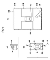
FIGS. 4A to 4C are respectively a back diagram of the own vehicle, a top diagram of the own vehicle, and a bird's-eye image diagram showing a bird's-eye image when a pole is present in a right rear side of the own vehicle. -
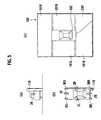
FIGS. 5A to 5C are respectively back diagram of the own vehicle, a top diagram of the own vehicle, and a bird's-eye image diagram showing an explanation about another bird's-eye image when the own vehicle approaches the pole. -
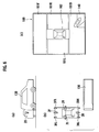
FIGS. 6A to 6C are respectively a back diagram of the own vehicle, a top diagram of the own vehicle, and a bird's-eye image diagram showing an explanation about a bird's-eye image when another vehicle is present in the right rear side of the own vehicle. -
FIGS. 7A to 7C are respectively a back diagram of the own vehicle, a top diagram of the own vehicle, and a bird's-eye image diagram showing an explanation about a bird's-eye image when the own vehicle approaches the other vehicle. -
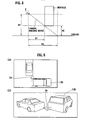
FIG. 8 is a diagram showing a cause of positional shifting of an obstacle in the bird's-eye image. -
FIGS. 9A and 9B are respectively a top diagram showing an actual state where the other vehicle is present within an obstacle detection range of the obstacle detection sensor of the own vehicle, and a perspective diagram showing the actual state where the other vehicle is present within the obstacle detection range of the obstacle detection sensor of the own vehicle. -
FIG. 10 is a perspective diagram showing an area where the obstacle detection range of the obstacle detection sensor is projected on a ground surface from a view point of the camera. -
FIGS. 11A and 11B are respectively a diagram showing a bird's-eye image when no other vehicle is present within the obstacle detection range of the own vehicle, and a diagram showing a bird's-eye image where the other vehicle is not in contact with the obstacle detection range of the own vehicle even if the other vehicle is present within the obstacle detection range of the own vehicle. -
FIG. 12 is a diagram showing a bird's-eye image where the area having the obstacle detection range of the obstacle detection sensor being projected on the ground surface from a view point of the camera is synthesized as an obstacle detection range image by the vehicle surrounding monitoring device to which the present invention is applied. -
FIG. 13 is a diagram showing a bird's-eye image where the obstacle detection range is sterically synthesized by the vehicle surrounding monitoring device to which the present invention is applied. -
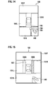
FIG. 14 is a diagram showing a bird's-eye image where an obstacle detection range image having the obstacle detection range projected on the ground surface is synthesized with a guide line indicating a projected position of the other vehicle on the ground surface by the vehicle surrounding monitoring device to which the present invention is applied. -
FIG. 15 is another diagram showing a bird's-eye image where an overlay image is synthesized to make a driver understand positional shifting of the obstacle. -
FIG. 16 is another diagram showing a bird's-eye image where an overlay image is synthesized to make a driver understand positional shifting of the obstacle. -
FIG. 17 is another diagram showing a bird's-eye image where an overlay image is synthesized to make a driver understand positional shifting of the obstacle. - Below, the embodiments of the present invention will be described with reference to the drawings.
- The present invention is applied to a vehicle surrounding monitoring device configured, for example, as shown in
FIG. 1 . In the vehicle surrounding monitoring device, at least one or more cameras 2-1, 2-2, ..., 2-N (simply referred to as "camera 2" generically hereinafter), a plurality of obstacle detection sensors (obstacle detection means) 3-1, 3-2, ..., 3-N (simply referred to as "obstacle sensor 3" generically hereinafter), and a display device 4 are connected to an image processing unit (image processing means) 1. The cameras 2-1, 2-2, ..., 2-N are arranged in different positions of an own vehicle, and imaging directions are different from one another. As in the case of thecamera 2, the obstacle sensors 3-1, 3-2, ..., 3-3 are arranged in different positions of the own vehicle, and obstacle detection ranges are different from one another. - Specifically, as shown in
FIG. 2 , the cameras 2-1, 2-2, ..., 2-N are, for example, super-wide-angle cameras where horizontal field angles are 180°, and include four cameras, i.e., acamera 2F for imaging a front side of the vehicle, acamera 2B for imaging a rear side, acamera 2R for imaging a right side, and acamera 2L for imaging a left side. Accordingly, thecameras image processing unit 1 described below, as in the case of a bird's-eye image (view point converted image) 100 subjected to image synthesis processing (view point conversion processing) to be displayed by the display unit 4 shown inFIG. 3 , a frontcamera display area 101F, a rearcamera display area 101B, a rightcamera display area 101R, and a leftcamera display area 101L, and can form images for understanding all the surroundings of the own vehicle. - The bird's-
eye image 100 is an image subjected to view point conversion processing as if to look down the own vehicle from above by using camera image data imaged by thecameras FIG. 2 . An image drawn roughly in the center of the bird's-eye image is an ownvehicle overlay image 102 having a size corresponding to a floor area of the own vehicle stored beforehand in an overlay image storage unit which is not shown. Black beltlike partition lines are arranged between the display areas of the bird's-eye image 100. Note that each display area can be allocated differently from the example according to an actual imaging area. - For the obstacle sensors 3-1, 3-2, ..., 3-3, ranges (obstacle detection ranges) provided with widths of angle of about 90° to 140° from installation positions in fan shapes to detect obstacles present in a distance of about 1 m from the own vehicle are set. As shown in
FIG. 2 , the obstacle sensors 3-1, 3-2, ..., 3-3 include four obstacle sensors, i.e., an obstacle sensor 3FR for detecting obstacles of front right direction, an obstacle sensor 3FL for detecting obstacles of front left direction, an obstacle sensor 3BR for detecting obstacles of rear right direction, and an obstacle sensor 3BL for detecting obstacles of rear left direction. These obstacle sensors 3FR, 3FL, 3BR, and 3BL are configured so that inFIG. 3 , obstacles present in a frontcamera display area 101F can be detected by the obstacle sensors 3FR and 3FL, obstacles present in a rearcamera display area 101B can be detected by the obstacle sensors 3BR and 3BL, obstacles present in a rightcamera display area 101R can be detected by the obstacle sensors 3FR and 3BR, and obstacles present in a leftcamera display area 101L can be detected by the obstacle sensors 3FL and 3BL. - As shown in
FIG. 2 , a case where the cameras 2-1, 2-2, ..., 2-N consist ofcameras - As shown in
FIG. 1 , theimage processing unit 1 enters camera image data of the vehicle surroundings imaged by thecameras frame buffer 11" generically hereinafter) which are input buffers corresponding to thecameras frame buffer 11 are used for forming a bird's-eye image 100 by image synthesis processing of apixel synthesis unit 13. - The
image processing unit 1 enters sensor signals from the obstacle sensors 3FR, 3FL, 3BR, and 3BL to a singleobstacle determination unit 12. Theobstacle determination unit 12 calculates presence of an obstacle around the own vehicle, and a position and a distance when an obstacle is present based on each entered sensor signal. Theobstacle determination unit 12 outputs the calculated presence of the obstacle, and the calculated position and distance of the obstacle to atable switching unit 14. - The
table switching unit 14 switches a table (address conversion table) to be referred to in the image synthesis processing of thepixel synthesis unit 13 to one of a plurality of address conversion tables among the plurality of address conversion tables stored in atable storage unit 15. - In the address conversion table stored in the
table storage unit 15, correspondence relationship between each pixel of the bird's-eye image 100 which is an output image output to the display device 4 and information for specifying image data to be stored in the pixel is described. Specifically, in the address conversion table, whether to store camera image data in each pixel of the bird's-eye image 100 which is the output image, whether to store an overlay image indicating the own vehicle or the obstacle, which of addresses in which of theframe buffers 11 image data is taken out from when the camera image data is stored, and which of pieces of color information is stored when the overlay image is stored are described. In other words, in the address conversion table, contents of image synthesis processing for which of the frame buffers or overlay image storage units not shown the camera image to form the bird's-eye image 100 is taken out from, and which of the address in the output buffer of a videosignal generation unit 16 the taken-out camera image data or the overlay image is stored are described. - The
pixel synthesis unit 13 refers to the address conversion table selected by the videosignal generation unit 16 to take out the camera image data stored in theframe buffer 11 or the overlay image indicating the own vehicle or the obstacle, and stores the image in the output buffer of the videosignal generation unit 16. Accordingly, thepixel synthesis unit 13 stores the bird's-eye image 100 obtained by synthesizing the plurality of camera image data imaged by thecameras signal generation unit 16. - Upon storage of the bird's-
eye image 100 of one frame in the output buffer by thepixel synthesis unit 13, the videosignal generation unit 16 outputs the bird's-eye image 100 to the display device 4 to display the image therein. Output timing of the bird's-eye image 100 from the output buffer of the videosignal generation unit 16 to the display device 4 has been preset in advance together with timing of the image synthesis processing of thepixel synthesis unit 13. - A
warning output unit 17 for outputting, when presence of an obstacle within the obstacle detection range of theobstacle sensor 3 is detected by theobstacle determination unit 12, a warning sound indicating the detection is connected to theobstacle determination unit 12. Thiswarning output unit 17 includes a speaker for outputting a predetermined warning sound to the driver. - Next, a specific example where the vehicle surrounding monitoring device configured in the aforementioned manner causes the display device 4 to display the bird's-
eye image 100 will be described. - For example, as shown in
FIGS. 4A and 4B , when apole 110 is present as an obstacle in a rear right side of the own vehicle, the bird's-eye image 100 includes, as shown inFIG. 4C , anobstacle image 120 in the rearcamera display area 101B below a right side of the ownvehicle overlay image 102. As in the case of thepole 110, when the obstacle stands vertically in contact with the ground surface, in the bird's-eye image 100, a contact surface between thepole 110 and the ground surface can be displayed in a correct position with respect to the own vehicle. When the vehicle is moved back straight in a state ofFIG. 4A , as shown inFIGS. 5A and 5B , contact of the own vehicle with thepole 110 can be understood. Additionally, as shown inFIG. 5C , theimage processing unit 1 forms an obstacle image 120' where thepole 110 of the rearcamera display area 101B is displayed to be distorted so that the obstacle image 120' can be displayed in contact with the ownvehicle overlay image 102. - As shown in
FIGS. 6A to 6C andFIGS. 7A to 7C , when theother vehicle 130 stopped in the position of thepole 110 is present inFIGS. 4A to 4C andFIGS. 5A to 5C , an obstacle present in a position closest to the own vehicle is a bumper of theother vehicle 130, and present at a predetermined height from the ground surface different from thepole 110. - When the obstacle is present above the ground surface as in the aforementioned case, depending on a positional relation with attaching heights of the
cameras other vehicle 130 in the bird's-eye image 100, occurs. In other words, as shown inFIGS. 6A and 6B , when the own vehicle is moved back straight, irrespective of a positional relation of potential contact with theother vehicle 130, as shown inFIG. 6C , there is a possibility of forming a bird's-eye image 100 where the own vehicle is not in contact with theother vehicle 130. Even when a stage is changed from the state ofFIGS. 6A and 6B , by straight movement-back of the own vehicle, to a state where the own vehicle is actually brought into contact with theother vehicle 130 as shown inFIGS. 7A and 7B , there is a possibility of forming a bird's-eye image 100 which includes an other vehicle image 140' which is not in contact as shown inFIG. 7C . - The phenomenon of the shifting of the positional relation between the own vehicle and the
other vehicle 130 in the bird's-eye image 100 is caused, as shown inFIG. 8 , by a principle of generating a bird's-eye image 100 itself where depending on a relation between a ground height H1 of thecamera 2 and a ground height H2 of the obstacle, as for the obstacle above the ground, a distance from thecamera 2 to the obstacle is imaged as if the obstacle is present in a position more away from thecamera 2 than that in an actual case. In other words, in reality, irrespective of only a distance D1 from thecamera 2 to the obstacle, the obstacle is imaged at a distance D2 within a camera imaging range, and thus the bird's-eye image 100 includes the obstacle in the position of the distance D2 greater than the distance D1. - More specifically, a case where the
other vehicle 130 is actually present as an obstacle within anobstacle detection range 3a of the obstacle sensor 3BR as shown in a diagram ofFIG. 9A where the own vehicle is seen from above and a diagram ofFIG. 9B where the own vehicle is seen from an oblique rear side will be considered. In this case, when an installation position of thecamera 2 is higher than an installation position of theobstacle sensor 3, theobstacle detection range 3a imaged by thecamera 2 includes, as shown inFIG. 10 , not only an area 3b where theobstacle detection range 3a is projected on the ground surface but also an area 3c of a range passed from the installation position of thecamera 2 through an end of theobstacle detection range 3a and projected on the ground surface. - Accordingly, in reality, even if the
other vehicle 130 is present within theobstacle detection range 3a, even when an obstacledetection range image 150 indicating the area 3b where theobstacle detection range 3a is projected vertically on the ground surface is synthesized with the bird's-eye image 100 shown inFIG. 11A , as shown inFIG. 11B , in a bird's-eye image 100 imaged by thecamera 2 and subjected to view point conversion, contact of another vehicle image 140 within theobstacle detection range 3a cannot be presented. - On the other hand, in the case of the vehicle surrounding monitoring device to which the present invention is applied, when an obstacle enters the
obstacle detection range 3a of theobstacle sensor 3, a warning sound is output from thewarning output unit 17, an image of theobstacle detection range 3a of theobstacle sensor 3 is simultaneously synthesized with an image of an obstacle imaged by thecamera 2 and included in the bird's-eye image 100 to be contact therewith, and the bird's-eye image 100 is displayed by the display device 4. - The image of the
obstacle detection range 3a of theobstacle sensor 3 is, as shown inFIG. 10 , an overlay image (referred to as obstacle detection range image hereinafter) indicating the area 3c of a range where theobstacle detection range 3a is projected on the ground surface with the attaching position of thecamera 2 set as a view point when theobstacle detection range 3a is imaged by thecamera 2. - Such a vehicle surrounding monitoring device directly displays the bird's-
eye image 100 processed by thepixel synthesis unit 13 at a normal time when theobstacle determination unit 12 detects no obstacle, and synthesizes an obstacle detection range image with the bird's-eye image 100 to display it thereon when theobstacle determination unit 12 detects an obstacle. Accordingly, in the vehicle surrounding monitoring device, upon detection of the obstacle, if the obstacle is present above and thus not in contact with the ground surface, presence of the obstacle within theobstacle detection range 3a of theobstacle sensor 3 is recognized in the bird's-eye image 100 subjected to the view point conversion. - Specifically, in the case of the positional relation between the own vehicle and the
other vehicle 130 shown inFIGS. 9A and 9B , when theobstacle determination unit 12 detects presence of an obstacle in the rear right side of the own vehicle, the bird's-eye image 100 shown inFIGS. 11A and 11B is switched to displaying shown in any one ofFIGS. 12 to 14 . When theobstacle determination unit 12 detects no more obstacle, the displaying is returned to the bird's-eye image 100 ofFIGS. 11A and 11B . - A bird's
eye image 100 shown inFIG. 12 is an image obtained by displaying another vehicle image 140 which is an obstacle detected in the rear right side of the own vehicle in the rearcamera display area 101B, and synthesizing semi-transparently an obstacledetection range image 151 indicating an area 3c of a range passed from the installation position of thecamera 2 through the end of theobstacle detection range 3a and projected on the ground surface with a predetermined area in the rear side of the own vehicle. - In the case of executing such displaying, the
obstacle determination unit 12 notifies the detection of the obstacle in the rear right side of the own vehicle to thetable switching unit 14. Thetable switching unit 14 selects an address conversion table to display the obstacledetection range image 151 in a rear side of the ownvehicle overlay image 102. Accordingly, thepixel synthesis unit 13 can form a bird's-eye image 100 where not the camera image data but the obstacledetection range image 151 is displayed in the rear side of the ownvehicle overlay image 102. Simultaneously, theobstacle determination unit 12 operates thewarning output unit 17 to give a warning about presence of theother vehicle 130 within theobstacle detection range 3a. - A bird's-
eye image 100 shown inFIG. 13 is an image obtained by synthesizing a steric obstacledetection range image 152 with theobstacle detection range 3a of the obstacle sensor 3BR which has detected theother vehicle 130. This obstacledetection range image 152 is configured by setting an area a (area 3b ofFIG. 10 ) where theobstacle detection range 3a is projected on the ground surface seen from above as a bottom surface, and connecting planes b and c corresponding to the area 3c shown inFIG. 10 to the area a of the bottom surface. These planes b and c are planes extending vertically from a boundary of the area where theobstacle detection range 3a of theobstacle sensor 3 is projected on the ground surface with the attaching position of thecamera 2 as a view point. - An end point d of the obstacle
detection range image 152 is, as shown inFIG. 10 , a point passed from the installation position of thecamera 2 through one upper end part of theobstacle detection range 3a and projected on the ground surface. An end point e of the obstacledetection range image 152 is, as shown inFIG. 10 , a point passed from the installation position of thecamera 2 through the other upper end part of theobstacle detection range 3a and projected on the ground surface. In this case, thetable switching unit 14 selects an address conversion table for displaying the steric obstacledetection range image 152 in the rear side of the ownvehicle overlay image 102. Steric surfaces b and c of the steric obstacledetection range image 152 are preferably displayed by different colors to facilitate differentiation of the steric surfaces b and c from each other. - Thus, by displaying the steric obstacle
detection range image 152 as the image of theobstacle detection range 3a, presence of theother vehicle 130 within theobstacle detection range 3a of theobstacle sensor 3 in its separated state from the ground surface can be presented. - Additionally, a bird's-
eye image 100 shown inFIG. 14 is an image obtained by synthesizing aguide line 153 in a position where theother vehicle image 140 present away from and above the ground surface is projected on the ground surface with the obstacledetection range image 150 of the area (area 3b ofFIG. 10 ) where theobstacle detection range 3a is projected on the ground surface. Theguide line 153 is a line where a car body part and a bumper part as ends of theother vehicle 130 are projected on the ground surface, and displayed in contact with the obstacledetection range image 150. - In this case, the
table switching unit 14 selects an address conversion table for displaying the obstacledetection range image 150 in the rear side of the ownvehicle overlay image 102. Thepixel synthesis unit 13 forms a bird's-eye image 100 by synthesizing theguide line 153 with a position of a distance calculated by theobstacle determination unit 12 where a part of theother vehicle 130 away from the ground surface is present. Thepixel synthesis unit 13 prestores distance coordinates from theobstacle sensor 3 in the bird's-eye image 100, and synthesizes theguide line 153 with the position of the distance to theother vehicle 130 calculated by theobstacle determination unit 12 in the bird's-eye image 100. Accordingly, theguide line 153 is displayed in a form where theother vehicle image 140 is projected on the ground surface. - Thus, the
guide line 153 is synthesized with the bird's-eye image 100 in a form of being stacked on the obstacledetection range image 150, whereby the presence of theother vehicle 130 within theobstacle detection range 3a can be presented to the driver. - Furthermore, as another method for enabling understanding of shifting of a positional relation between the own
vehicle overlay image 102 and theother vehicle image 140 in the bird's-eye image 100 from an actual positional relation between the own vehicle and theother vehicle 130, as shown inFIGS. 15 to 17 , the display form of the ownvehicle overlay image 102 drawn roughly in the center of the bird's-eye image 100 may be changed. - In a bird's-
eye image 100 shown inFIG. 15 , theother vehicle image 140 is displayed in a rear right side,overlay images vehicle overlay image 102, and theoverlay image 160B in a direction where theother vehicle image 140 is present is displayed by a warning color. Thetable switching unit 14 selects an address conversion table for displaying respectively thesemitransparent overlay image 160A and the warningcolor overlay image 160B on both sides of the ownvehicle overlay image 102. Accordingly, an area of the ownvehicle overlay image 102 is set larger than a floor area of the own vehicle. - In a bird's-
eye image 100 shown inFIG. 16 , the ownvehicle overlay image 102 is changed to a virtual own vehicle overlay image 102' enlarged in a horizontal direction. In this case, thetable switching unit 14 selects an address conversion table for displaying an own vehicle overlay image 102' where a width of the ownvehicle overlay image 102 is increased. - Furthermore, as shown in
FIG. 17 , the ownvehicle overlay image 102 is enlarged horizontally and sterically to be changed to a virtual own vehicle overlay image 102'. In this case, thetable switching unit 14 selects an address conversion table for increasing a width of the ownvehicle overlay image 102, and displaying the steric own vehicle overlay image 102'. - Thus, when the obstacle is detected, by enlarging the own
vehicle overlay image 102 of the size corresponding to the floor area of the own vehicle in the width direction, a positional relation between the own vehicle and theother vehicle image 140 which are brought into contact with each other when the own vehicle is moved back straight can be understood by the driver. - As shown in
FIGS. 15 to 17 , when the ownvehicle overlay image 102 is enlarged to be displayed, by thewarning output unit 17, the presence of theother vehicle 130 within theobstacle detection range 3a may be understood by a warning sound. Accordingly, in reality, there is a possibility of contact between the obstacle detected by theobstacle sensor 3 and the own vehicle, and this possibility can be surely presented to the driver. - The aforementioned embodiment is only an example of the present invention. The invention is not limited to the embodiment. Needless to say, even other embodiments can be employed, and various changes can be made according to design or the like without departing from the technical ideas of the invention.
- In other words, in the aforementioned display example of the bird's-
eye image 100, the obstacle detection range image is displayed in the semitransparent manner. Not limited to this, however, the obstacle detection range image may be flashed. - According to the present invention, when an obstacle is detected, a warning is given, and images are synthesized so that an image of the obstacle is brought into contact with the obstacle detection range. Thus, even when the obstacle is present away from the ground surface, and even when positional shifting of the obstacle occurs in a view point converted image, displaying can be realized where no uncomfortable feelings are given in a positional relation between the obstacle detection range and the obstacle.
Claims (7)
- A vehicle surrounding monitoring device comprising:at least one camera installed in an own vehicle to image a video around the own vehicle;obstacle detection means installed in the own vehicle to detect an obstacle in an obstacle detection area;image processing means for converting a camera image imaged by the camera into a view point converted image seen from a virtual view point above the own vehicle; anddisplay means for displaying the view point conversion image converted by the image processing means,characterized in that simultaneously when a warning is given by a warning sound upon entry of an obstacle within an obstacle detection range of the obstacle detection means, the image processing means synthesizes an image of the obstacle detection range of the obstacle detection means with an obstacle image imaged by the camera and included in the view point converted image to be in contact therewith.
- The vehicle surrounding monitoring device according to claim 1,
characterized in that the image processing means sets an image obtained by projecting the obstacle detection range of the obstacle detection means on a ground surface with an attaching position of the camera set as a view point as the image of the obstacle detection range, and synthesizes the image of the obstacle detection range projected on the ground surface with the view point converted image seen from the virtual view point. - The vehicle surrounding monitoring device according to claim 1,
characterized in that the image processing means sterically synthesizes the image of the obstacle detection range of the obstacle detection means with the view point converted image. - The vehicle surrounding monitoring device according to claim 3,
characterized in that the image of the obstacle detection range consists of a stereoscopic image included an image of an area where the obstacle detection range is projected on the ground surface, and a plane extending vertically from a boundary of the area where the obstacle detection range of the obstacle detection means is projected on the ground surface with the attaching position of the camera set as the view point, and is synthesized with the view point converted image to be displayed. - The vehicle surrounding monitoring device according to claim 1,
characterized in that:the obstacle detection means detects an obstacle in space away from the ground surface; andan image of an area where the obstacle detection range is projected on the ground surface, and an image displayed in a position where the space obstacle detected by the obstacle detection means is projected on the ground surface and brought into contact with the image of the area where the obstacle detection range is projected on the ground surface are synthesized with the view point converted image to be displayed. - The vehicle surrounding monitoring device according to claim 1,
characterized in that the image processing means displays the image of the obstacle detection range in a semitransparent manner. - A vehicle surrounding monitoring method, characterized by including:imaging a video around an own vehicle by a camera installed in the own vehicle;detecting an obstacle within an imaging range of the camera by an obstacle detection sensor; andwhen presence of an obstacle is detected by the obstacle detection sensor, giving a warning by a warning sound, and simultaneously synthesizing an image of an obstacle detection range of the obstacle detection sensor to be in contact with an obstacle imaged by the camera and included in a view point converted image.
Applications Claiming Priority (2)
| Application Number | Priority Date | Filing Date | Title |
|---|---|---|---|
| JP2005224489 | 2005-08-02 | ||
| PCT/JP2006/315114 WO2007015446A1 (en) | 2005-08-02 | 2006-07-31 | Device for monitoring around vehicle and method for monitoring around vehicle |
Publications (3)
| Publication Number | Publication Date |
|---|---|
| EP1916846A1 true EP1916846A1 (en) | 2008-04-30 |
| EP1916846A4 EP1916846A4 (en) | 2009-04-22 |
| EP1916846B1 EP1916846B1 (en) | 2016-09-14 |
Family
ID=37708726
Family Applications (1)
| Application Number | Title | Priority Date | Filing Date |
|---|---|---|---|
| EP06781992.0A Active EP1916846B1 (en) | 2005-08-02 | 2006-07-31 | Device and method for monitoring vehicle surroundings |
Country Status (4)
| Country | Link |
|---|---|
| US (1) | US8885045B2 (en) |
| EP (1) | EP1916846B1 (en) |
| JP (1) | JP4760831B2 (en) |
| WO (1) | WO2007015446A1 (en) |
Cited By (7)
| Publication number | Priority date | Publication date | Assignee | Title |
|---|---|---|---|---|
| EP2130736B1 (en) * | 2008-06-04 | 2012-05-02 | Aisin Seiki Kabushiki Kaisha | Surrounding recognition support system |
| WO2011153652A3 (en) * | 2010-06-10 | 2012-06-28 | Safemine Ag | Method and control unit for controlling a display |
| US8319614B2 (en) | 2008-07-25 | 2012-11-27 | Nissan Motor Co., Ltd. | Parking assistance apparatus and parking assistance method |
| US8498770B2 (en) | 2007-12-26 | 2013-07-30 | Nissan Motor Co., Ltd. | Vehicle parking assist system and method |
| EP2750382A4 (en) * | 2011-08-26 | 2014-08-13 | Panasonic Corp | DRIVING AID |
| EP2797793B1 (en) * | 2011-12-29 | 2019-03-06 | Intel Corporation | Systems and methods for proximal object awareness |
| EP3785996A1 (en) * | 2019-04-19 | 2021-03-03 | Autoequips Tech Co., Ltd. | Integrated alarm system for vehicles |
Families Citing this family (64)
| Publication number | Priority date | Publication date | Assignee | Title |
|---|---|---|---|---|
| WO2000020257A1 (en) * | 1998-10-08 | 2000-04-13 | Matsushita Electric Industrial Co., Ltd. | Driving assisting device and recording medium |
| JP4512293B2 (en) * | 2001-06-18 | 2010-07-28 | パナソニック株式会社 | Monitoring system and monitoring method |
| JP4893945B2 (en) * | 2007-02-06 | 2012-03-07 | 株式会社デンソー | Vehicle periphery monitoring device |
| DE102007045562A1 (en) * | 2007-09-24 | 2009-04-02 | Robert Bosch Gmbh | Control device for a display device of a parking device and method for representation |
| JP5090126B2 (en) * | 2007-10-23 | 2012-12-05 | アルパイン株式会社 | In-vehicle imaging device |
| JP5057936B2 (en) * | 2007-11-09 | 2012-10-24 | アルパイン株式会社 | Bird's-eye image generation apparatus and method |
| JP5108605B2 (en) * | 2008-04-23 | 2012-12-26 | 三洋電機株式会社 | Driving support system and vehicle |
| JP5300309B2 (en) * | 2008-04-24 | 2013-09-25 | ダイハツ工業株式会社 | Obstacle recognition device |
| JP5177515B2 (en) * | 2008-06-02 | 2013-04-03 | アイシン精機株式会社 | Peripheral recognition support system |
| JP5068779B2 (en) * | 2009-02-27 | 2012-11-07 | 現代自動車株式会社 | Vehicle surroundings overhead image display apparatus and method |
| JP5344227B2 (en) * | 2009-03-25 | 2013-11-20 | アイシン精機株式会社 | Vehicle periphery monitoring device |
| US20100253780A1 (en) * | 2009-04-03 | 2010-10-07 | Shih-Hsiung Li | Vehicle auxiliary device |
| DE102009024062A1 (en) * | 2009-06-05 | 2010-12-09 | Valeo Schalter Und Sensoren Gmbh | Apparatus and method for displaying objects in a vehicle environment |
| AU2009347705B2 (en) | 2009-06-12 | 2014-01-16 | Safemine Ag | Movable object proximity warning system |
| US20110080482A1 (en) * | 2009-10-06 | 2011-04-07 | Wen-Ching Shih | Monitor-displayed device for car rear vision |
| US8994557B2 (en) | 2009-12-11 | 2015-03-31 | Safemine Ag | Modular collision warning apparatus and method for operating the same |
| MX2012014399A (en) * | 2010-06-09 | 2013-02-01 | Nissan Motor | Parking mode selection device and method. |
| DE112010005661B4 (en) * | 2010-06-15 | 2014-10-30 | Mitsubishi Electric Corporation | Vehicle environment monitoring device |
| JP5520142B2 (en) * | 2010-06-21 | 2014-06-11 | 株式会社日立製作所 | Railway vehicle status monitoring device |
| US20120249342A1 (en) * | 2011-03-31 | 2012-10-04 | Koehrsen Craig L | Machine display system |
| TWI421624B (en) * | 2011-04-01 | 2014-01-01 | Ind Tech Res Inst | Adaptive surrounding view monitoring apparatus and method thereof |
| WO2012164804A1 (en) * | 2011-06-02 | 2012-12-06 | パナソニック株式会社 | Object detection device, object detection method, and object detection program |
| JP5587499B2 (en) * | 2011-06-07 | 2014-09-10 | 株式会社小松製作所 | Work vehicle perimeter monitoring device |
| DE102011084554A1 (en) * | 2011-10-14 | 2013-04-18 | Robert Bosch Gmbh | Method for displaying a vehicle environment |
| WO2013086249A2 (en) | 2011-12-09 | 2013-06-13 | Magna Electronics, Inc. | Vehicle vision system with customized display |
| CN103649426B (en) * | 2012-01-27 | 2016-05-11 | 斗山英维高株式会社 | The processing safety of building machinery improves device |
| US9598836B2 (en) | 2012-03-29 | 2017-03-21 | Harnischfeger Technologies, Inc. | Overhead view system for a shovel |
| JP6029306B2 (en) * | 2012-03-29 | 2016-11-24 | 住友建機株式会社 | Perimeter monitoring equipment for work machines |
| DE102012106691B4 (en) * | 2012-07-24 | 2024-07-11 | Valeo Schalter Und Sensoren Gmbh | Alternative installation of a concealed ultrasonic sensor in the vehicle |
| US10163348B2 (en) * | 2012-08-01 | 2018-12-25 | Toyota Jidosha Kabushiki Kaisha | Drive assist device |
| US9704361B1 (en) * | 2012-08-14 | 2017-07-11 | Amazon Technologies, Inc. | Projecting content within an environment |
| US9674490B2 (en) * | 2013-04-18 | 2017-06-06 | Magna Electronics Inc. | Vision system for vehicle with adjustable cameras |
| EP2860718B1 (en) * | 2013-10-10 | 2018-12-05 | U-Shin France | Detection device for a motor vehicle and associated methods for detecting an obstacle and for opening a movable panel of the motor vehicle |
| US9598012B2 (en) * | 2014-03-11 | 2017-03-21 | Toyota Motor Engineering & Manufacturing North America, Inc. | Surroundings monitoring system for a vehicle |
| DE102014107235A1 (en) * | 2014-05-22 | 2015-11-26 | Dr. Ing. H.C. F. Porsche Aktiengesellschaft | A method of displaying a vehicle environment on a display device; a display device; a system of a plurality of image capture units and a display device; a computer program |
| US10525883B2 (en) | 2014-06-13 | 2020-01-07 | Magna Electronics Inc. | Vehicle vision system with panoramic view |
| US11472338B2 (en) | 2014-09-15 | 2022-10-18 | Magna Electronics Inc. | Method for displaying reduced distortion video images via a vehicular vision system |
| EP3207336A4 (en) * | 2014-10-14 | 2018-06-20 | Sikorsky Aircraft Corporation | Synthetic vision augmented with multispectral sensing |
| KR101629577B1 (en) * | 2014-12-10 | 2016-06-13 | 현대오트론 주식회사 | Monitoring method and apparatus using a camera |
| US9610893B2 (en) | 2015-03-18 | 2017-04-04 | Car1St Technologies, Llc | Methods and systems for providing alerts to a driver of a vehicle via condition detection and wireless communications |
| US10328855B2 (en) | 2015-03-18 | 2019-06-25 | Uber Technologies, Inc. | Methods and systems for providing alerts to a connected vehicle driver and/or a passenger via condition detection and wireless communications |
| JP6224029B2 (en) * | 2015-05-21 | 2017-11-01 | 富士通テン株式会社 | Image processing apparatus and image processing method |
| US10486599B2 (en) * | 2015-07-17 | 2019-11-26 | Magna Mirrors Of America, Inc. | Rearview vision system for vehicle |
| US9787951B2 (en) * | 2015-12-18 | 2017-10-10 | Serge Kannon | Vehicle proximity warning system |
| JP2017118409A (en) * | 2015-12-25 | 2017-06-29 | 株式会社Jvcケンウッド | VEHICLE DISPLAY DEVICE AND VEHICLE DISPLAY METHOD |
| JP6950775B2 (en) * | 2016-01-13 | 2021-10-13 | 株式会社Jvcケンウッド | Vehicle display devices, vehicle display methods and programs |
| WO2017154317A1 (en) * | 2016-03-09 | 2017-09-14 | 株式会社Jvcケンウッド | Vehicle display control device, vehicle display system, vehicle display control method, and program |
| JP6256509B2 (en) * | 2016-03-30 | 2018-01-10 | マツダ株式会社 | Electronic mirror control device |
| JP6595401B2 (en) | 2016-04-26 | 2019-10-23 | 株式会社Soken | Display control device |
| US10501018B2 (en) * | 2016-07-18 | 2019-12-10 | Panasonic Automotive Systems Company Of America, Division Of Panasonic Corporation Of North America | Head up side view mirror |
| US10279786B2 (en) * | 2016-12-06 | 2019-05-07 | Aptiv Technologies Limited | Automatic braking system |
| JP6579144B2 (en) * | 2017-03-28 | 2019-09-25 | 株式会社Soken | Obstacle detection device |
| US10913434B2 (en) | 2017-06-01 | 2021-02-09 | Aptiv Technologies Limited | Automatic braking system for slow moving objects |
| JP2019012915A (en) * | 2017-06-30 | 2019-01-24 | クラリオン株式会社 | Image processing apparatus and image conversion method |
| TWI688502B (en) * | 2018-02-14 | 2020-03-21 | 先進光電科技股份有限公司 | Apparatus for warning of vehicle obstructions |
| JP7147255B2 (en) * | 2018-05-11 | 2022-10-05 | トヨタ自動車株式会社 | image display device |
| EP3627183B1 (en) * | 2018-09-18 | 2022-05-11 | KNORR-BREMSE Systeme für Nutzfahrzeuge GmbH | Control system for autonomous driving of a vehicle |
| US10967792B1 (en) * | 2018-10-12 | 2021-04-06 | Roger Stafford | Apparatus for monitoring periphery of a vehicle and displaying a view of the periphery on a display device |
| US10497232B1 (en) * | 2019-03-01 | 2019-12-03 | Motorola Solutions, Inc. | System and method for dynamic vehicular threat detection perimeter modification for an exited vehicular occupant |
| JP7168091B2 (en) * | 2019-08-02 | 2022-11-09 | 日産自動車株式会社 | Image processing device and image processing method |
| JP7443705B2 (en) * | 2019-09-12 | 2024-03-06 | 株式会社アイシン | Peripheral monitoring device |
| WO2022191813A1 (en) * | 2021-03-08 | 2022-09-15 | Roger Stafford | An apparatus for monitoring periphery of a vehicle and displaying a view of the periphery on a display device |
| JP7577600B2 (en) | 2021-04-21 | 2024-11-05 | 株式会社東芝 | 3D map estimation device and obstacle detection device |
| JP7759739B2 (en) * | 2021-05-28 | 2025-10-24 | 株式会社Subaru | Vehicle exterior imaging device |
Family Cites Families (58)
| Publication number | Priority date | Publication date | Assignee | Title |
|---|---|---|---|---|
| HU178550B (en) | 1978-04-22 | 1982-05-28 | Girling Ltd | Non-skid brake mechanism for multiple-axle wheeled vehicles |
| EP0752687B1 (en) * | 1995-06-09 | 2003-05-07 | Xanavi Informatics Corporation | Map display apparatus |
| US6275231B1 (en) | 1997-08-01 | 2001-08-14 | American Calcar Inc. | Centralized control and management system for automobiles |
| JPH11168754A (en) | 1997-12-03 | 1999-06-22 | Mr System Kenkyusho:Kk | Image recording method, image database system, image recording device, and storage medium for computer program |
| WO2000020257A1 (en) * | 1998-10-08 | 2000-04-13 | Matsushita Electric Industrial Co., Ltd. | Driving assisting device and recording medium |
| EP1179958B1 (en) | 1999-04-16 | 2012-08-08 | Panasonic Corporation | Image processing device and monitoring system |
| US7366595B1 (en) | 1999-06-25 | 2008-04-29 | Seiko Epson Corporation | Vehicle drive assist system |
| US6963661B1 (en) * | 1999-09-09 | 2005-11-08 | Kabushiki Kaisha Toshiba | Obstacle detection system and method therefor |
| JP4660872B2 (en) * | 2000-02-09 | 2011-03-30 | ソニー株式会社 | Driving support device and driving support method |
| US7370983B2 (en) | 2000-03-02 | 2008-05-13 | Donnelly Corporation | Interior mirror assembly with display |
| US6734896B2 (en) | 2000-04-28 | 2004-05-11 | Matsushita Electric Industrial Co., Ltd. | Image processor and monitoring system |
| JP2001315603A (en) | 2000-05-09 | 2001-11-13 | Matsushita Electric Ind Co Ltd | Driving support device |
| JP3599639B2 (en) | 2000-05-26 | 2004-12-08 | 松下電器産業株式会社 | Image processing device |
| EP1168248A3 (en) | 2000-06-30 | 2003-12-10 | Matsushita Electric Industrial Co., Ltd. | Rendering device |
| EP1303140A4 (en) | 2000-07-19 | 2007-01-17 | Matsushita Electric Industrial Co Ltd | MONITORING SYSTEM |
| JP3372944B2 (en) | 2000-07-19 | 2003-02-04 | 松下電器産業株式会社 | Monitoring system |
| JP3773433B2 (en) | 2000-10-11 | 2006-05-10 | シャープ株式会社 | Ambient monitoring device for moving objects |
| JP2002199257A (en) | 2000-12-25 | 2002-07-12 | Sharp Corp | Imaging device |
| JP3645196B2 (en) | 2001-02-09 | 2005-05-11 | 松下電器産業株式会社 | Image synthesizer |
| JP2002359839A (en) * | 2001-03-29 | 2002-12-13 | Matsushita Electric Ind Co Ltd | Rear view camera image display method and device |
| JP3297040B1 (en) * | 2001-04-24 | 2002-07-02 | 松下電器産業株式会社 | Image composing and displaying method of vehicle-mounted camera and apparatus therefor |
| JP2002316602A (en) * | 2001-04-24 | 2002-10-29 | Matsushita Electric Ind Co Ltd | Method and apparatus for displaying captured image of vehicle-mounted camera |
| JP2002334322A (en) * | 2001-05-10 | 2002-11-22 | Sharp Corp | Perspective projection image generation system, perspective projection image generation method, perspective projection image generation program, and storage medium storing perspective projection image generation program |
| JP4156214B2 (en) * | 2001-06-13 | 2008-09-24 | 株式会社デンソー | Vehicle periphery image processing apparatus and recording medium |
| JP4512293B2 (en) * | 2001-06-18 | 2010-07-28 | パナソニック株式会社 | Monitoring system and monitoring method |
| JP4641125B2 (en) | 2001-08-23 | 2011-03-02 | クラリオン株式会社 | Joint processing method for image composition, image signal processing apparatus therefor, and vehicle surrounding monitoring display apparatus using the same |
| EP1291668B1 (en) | 2001-09-07 | 2005-11-30 | Matsushita Electric Industrial Co., Ltd. | Vehicle surroundings display device and image providing system |
| KR100866450B1 (en) * | 2001-10-15 | 2008-10-31 | 파나소닉 주식회사 | Automobile surrounding observation device and method for adjusting the same |
| US6636258B2 (en) * | 2001-10-19 | 2003-10-21 | Ford Global Technologies, Llc | 360° vision system for a vehicle |
| JP2003132349A (en) * | 2001-10-24 | 2003-05-09 | Matsushita Electric Ind Co Ltd | Drawing equipment |
| JP3819284B2 (en) * | 2001-11-29 | 2006-09-06 | クラリオン株式会社 | Vehicle perimeter monitoring device |
| JP3855814B2 (en) * | 2002-03-22 | 2006-12-13 | 日産自動車株式会社 | Image processing apparatus for vehicle |
| AU2003225228A1 (en) * | 2002-05-03 | 2003-11-17 | Donnelly Corporation | Object detection system for vehicle |
| JP3871614B2 (en) * | 2002-06-12 | 2007-01-24 | 松下電器産業株式会社 | Driving assistance device |
| DE10227171B4 (en) | 2002-06-18 | 2019-09-26 | Bayerische Motoren Werke Aktiengesellschaft | Method and device for visualizing the environment of a vehicle with distance-dependent fusion of an infrared and a visual image |
| JP3968271B2 (en) | 2002-06-25 | 2007-08-29 | 株式会社オートネットワーク技術研究所 | Vehicle periphery visual recognition device |
| JP3895238B2 (en) * | 2002-08-28 | 2007-03-22 | 株式会社東芝 | Obstacle detection apparatus and method |
| JP3868876B2 (en) | 2002-09-25 | 2007-01-17 | 株式会社東芝 | Obstacle detection apparatus and method |
| DE10247563A1 (en) | 2002-10-11 | 2004-04-22 | Valeo Schalter Und Sensoren Gmbh | Method and system for assisting the driver |
| JP2004240480A (en) | 2003-02-03 | 2004-08-26 | Matsushita Electric Ind Co Ltd | Driving support device |
| JP4286556B2 (en) | 2003-02-24 | 2009-07-01 | 株式会社東芝 | Image display device |
| JP2004274114A (en) * | 2003-03-05 | 2004-09-30 | Nissan Motor Co Ltd | Image display device and image display method |
| DE10352733A1 (en) | 2003-04-04 | 2004-10-28 | Takata-Petri Ag | Motor vehicle steering wheel has a driver communications interface permitting display of information to the driver and input of commands by the driver with minimal distraction from the driving situation |
| JP2004354326A (en) * | 2003-05-30 | 2004-12-16 | Denso Corp | Vehicle periphery display device |
| US20050075770A1 (en) * | 2003-10-07 | 2005-04-07 | Taylor Ronald M. | Motor vehicle back-up system |
| US7298247B2 (en) * | 2004-04-02 | 2007-11-20 | Denso Corporation | Vehicle periphery monitoring system |
| EP1748654A4 (en) * | 2004-04-27 | 2013-01-02 | Panasonic Corp | VISUALIZATION OF CIRCUMFERENCE OF A VEHICLE |
| US20060038895A1 (en) * | 2004-08-19 | 2006-02-23 | Nissan Motor, Co., Ltd. | Image processing device |
| JP2006072830A (en) | 2004-09-03 | 2006-03-16 | Aisin Aw Co Ltd | Operation supporting system and operation supporting module |
| JP4560716B2 (en) * | 2004-09-28 | 2010-10-13 | アイシン精機株式会社 | Vehicle periphery monitoring system |
| US7881496B2 (en) * | 2004-09-30 | 2011-02-01 | Donnelly Corporation | Vision system for vehicle |
| JP4254719B2 (en) | 2005-02-01 | 2009-04-15 | 株式会社デンソー | Vehicle display device |
| EP1696669B1 (en) * | 2005-02-24 | 2013-07-03 | Aisin Seiki Kabushiki Kaisha | Vehicle surrounding monitoring device |
| US7884556B2 (en) | 2005-09-16 | 2011-02-08 | Advanced Color Lighting, Inc. | Color-changing light array device |
| JP2007094045A (en) * | 2005-09-29 | 2007-04-12 | Matsushita Electric Ind Co Ltd | Navigation device, navigation method, and vehicle |
| SE530287C2 (en) | 2005-10-11 | 2008-04-22 | Scania Cv Abp | Warning system for a motor vehicle fitted with a parking brake |
| US7830276B2 (en) | 2007-06-18 | 2010-11-09 | Honeywell International Inc. | System and method for displaying required navigational performance corridor on aircraft map display |
| JP5120880B2 (en) | 2007-10-15 | 2013-01-16 | アルパイン株式会社 | Image processing apparatus and image processing method |
-
2006
- 2006-07-31 WO PCT/JP2006/315114 patent/WO2007015446A1/en not_active Ceased
- 2006-07-31 EP EP06781992.0A patent/EP1916846B1/en active Active
- 2006-07-31 US US11/997,515 patent/US8885045B2/en active Active
- 2006-07-31 JP JP2007529249A patent/JP4760831B2/en active Active
Cited By (14)
| Publication number | Priority date | Publication date | Assignee | Title |
|---|---|---|---|---|
| US8498770B2 (en) | 2007-12-26 | 2013-07-30 | Nissan Motor Co., Ltd. | Vehicle parking assist system and method |
| EP2130736B1 (en) * | 2008-06-04 | 2012-05-02 | Aisin Seiki Kabushiki Kaisha | Surrounding recognition support system |
| US8248220B2 (en) | 2008-06-04 | 2012-08-21 | Aisin Seiki Kabushiki Kaisha | Surrounding recognition support system |
| US8319614B2 (en) | 2008-07-25 | 2012-11-27 | Nissan Motor Co., Ltd. | Parking assistance apparatus and parking assistance method |
| WO2011153652A3 (en) * | 2010-06-10 | 2012-06-28 | Safemine Ag | Method and control unit for controlling a display |
| US10970562B2 (en) | 2011-08-26 | 2021-04-06 | Panasonic Intellectual Property Management Co., Ltd. | Display apparatus |
| US10235575B2 (en) | 2011-08-26 | 2019-03-19 | Panasonic Intellectual Property Management Co., Ltd. | Driving assistance apparatus |
| EP2750382A4 (en) * | 2011-08-26 | 2014-08-13 | Panasonic Corp | DRIVING AID |
| US11657618B2 (en) | 2011-08-26 | 2023-05-23 | Panasonic Intellectual Property Management Co., Ltd. | Display apparatus |
| US12214510B2 (en) | 2011-08-26 | 2025-02-04 | Panasonic Automotive Systems Co., Ltd. | Display apparatus |
| US12220825B2 (en) | 2011-08-26 | 2025-02-11 | Panasonic Automotive Systems Co., Ltd. | Display apparatus |
| US12361719B2 (en) | 2011-08-26 | 2025-07-15 | Panasonic Automotive Systems Co., Ltd. | Display apparatus |
| EP2797793B1 (en) * | 2011-12-29 | 2019-03-06 | Intel Corporation | Systems and methods for proximal object awareness |
| EP3785996A1 (en) * | 2019-04-19 | 2021-03-03 | Autoequips Tech Co., Ltd. | Integrated alarm system for vehicles |
Also Published As
| Publication number | Publication date |
|---|---|
| EP1916846A4 (en) | 2009-04-22 |
| WO2007015446A1 (en) | 2007-02-08 |
| JP4760831B2 (en) | 2011-08-31 |
| EP1916846B1 (en) | 2016-09-14 |
| US20100220189A1 (en) | 2010-09-02 |
| JPWO2007015446A1 (en) | 2009-02-19 |
| US8885045B2 (en) | 2014-11-11 |
Similar Documents
| Publication | Publication Date | Title |
|---|---|---|
| US8885045B2 (en) | Device and method for monitoring vehicle surroundings | |
| CN103988499B (en) | Vehicle periphery monitoring apparatus | |
| JP5454934B2 (en) | Driving assistance device | |
| JP5922866B2 (en) | System and method for providing guidance information to a vehicle driver | |
| JP5962927B2 (en) | Overhead image generation apparatus, overhead image generation method, and overhead image generation program | |
| US20170140542A1 (en) | Vehicular image processing apparatus and vehicular image processing system | |
| JP2009524171A (en) | How to combine multiple images into a bird's eye view image | |
| CN107027329B (en) | Stitches partial images of the surroundings of the travel tool into one image | |
| US20130038734A1 (en) | Driving support apparatus | |
| JP5213063B2 (en) | Vehicle display device and display method | |
| WO2002089485A1 (en) | Method and apparatus for displaying pickup image of camera installed in vehicle | |
| WO2012096058A1 (en) | Image generating device | |
| JP2009206747A (en) | Ambient condition monitoring system for vehicle, and video display method | |
| CN114179725B (en) | Display device for vehicle | |
| US20130050490A1 (en) | Drive assisting apparatus | |
| JP2004240480A (en) | Driving support device | |
| JP2011030078A (en) | Image display device for vehicle | |
| JP2006252389A (en) | Perimeter monitoring device | |
| JP2012257107A (en) | Image generating device | |
| WO2010134240A1 (en) | Parking assistance device, parking assistance method, and parking assistance program | |
| JPWO2011013813A1 (en) | In-vehicle device and image processing program | |
| JP2007089081A (en) | Image display device for vehicle | |
| JP4256702B2 (en) | Image display method, image display apparatus, and image processing apparatus | |
| JP5691339B2 (en) | Driving assistance device | |
| JP2004040523A (en) | Vehicle periphery monitoring device |
Legal Events
| Date | Code | Title | Description |
|---|---|---|---|
| PUAI | Public reference made under article 153(3) epc to a published international application that has entered the european phase |
Free format text: ORIGINAL CODE: 0009012 |
|
| 17P | Request for examination filed |
Effective date: 20080220 |
|
| AK | Designated contracting states |
Kind code of ref document: A1 Designated state(s): DE FR GB |
|
| DAX | Request for extension of the european patent (deleted) | ||
| RBV | Designated contracting states (corrected) |
Designated state(s): DE FR GB |
|
| A4 | Supplementary search report drawn up and despatched |
Effective date: 20090323 |
|
| 17Q | First examination report despatched |
Effective date: 20120430 |
|
| GRAP | Despatch of communication of intention to grant a patent |
Free format text: ORIGINAL CODE: EPIDOSNIGR1 |
|
| INTG | Intention to grant announced |
Effective date: 20160607 |
|
| GRAS | Grant fee paid |
Free format text: ORIGINAL CODE: EPIDOSNIGR3 |
|
| GRAA | (expected) grant |
Free format text: ORIGINAL CODE: 0009210 |
|
| AK | Designated contracting states |
Kind code of ref document: B1 Designated state(s): DE FR GB |
|
| REG | Reference to a national code |
Ref country code: GB Ref legal event code: FG4D |
|
| REG | Reference to a national code |
Ref country code: DE Ref legal event code: R096 Ref document number: 602006050290 Country of ref document: DE |
|
| REG | Reference to a national code |
Ref country code: FR Ref legal event code: PLFP Year of fee payment: 12 |
|
| REG | Reference to a national code |
Ref country code: DE Ref legal event code: R097 Ref document number: 602006050290 Country of ref document: DE |
|
| PLBE | No opposition filed within time limit |
Free format text: ORIGINAL CODE: 0009261 |
|
| STAA | Information on the status of an ep patent application or granted ep patent |
Free format text: STATUS: NO OPPOSITION FILED WITHIN TIME LIMIT |
|
| 26N | No opposition filed |
Effective date: 20170615 |
|
| REG | Reference to a national code |
Ref country code: FR Ref legal event code: PLFP Year of fee payment: 13 |
|
| PGFP | Annual fee paid to national office [announced via postgrant information from national office to epo] |
Ref country code: GB Payment date: 20250619 Year of fee payment: 20 |
|
| PGFP | Annual fee paid to national office [announced via postgrant information from national office to epo] |
Ref country code: FR Payment date: 20250620 Year of fee payment: 20 |
|
| PGFP | Annual fee paid to national office [announced via postgrant information from national office to epo] |
Ref country code: DE Payment date: 20250620 Year of fee payment: 20 |