EP1916668A1 - Vertical spring wedge - Google Patents
Vertical spring wedge Download PDFInfo
- Publication number
- EP1916668A1 EP1916668A1 EP20070118789 EP07118789A EP1916668A1 EP 1916668 A1 EP1916668 A1 EP 1916668A1 EP 20070118789 EP20070118789 EP 20070118789 EP 07118789 A EP07118789 A EP 07118789A EP 1916668 A1 EP1916668 A1 EP 1916668A1
- Authority
- EP
- European Patent Office
- Prior art keywords
- wedge
- bracket
- guide rods
- vertical spring
- spring
- Prior art date
- Legal status (The legal status is an assumption and is not a legal conclusion. Google has not performed a legal analysis and makes no representation as to the accuracy of the status listed.)
- Granted
Links
Images



Classifications
-
- F—MECHANICAL ENGINEERING; LIGHTING; HEATING; WEAPONS; BLASTING
- F16—ENGINEERING ELEMENTS AND UNITS; GENERAL MEASURES FOR PRODUCING AND MAINTAINING EFFECTIVE FUNCTIONING OF MACHINES OR INSTALLATIONS; THERMAL INSULATION IN GENERAL
- F16L—PIPES; JOINTS OR FITTINGS FOR PIPES; SUPPORTS FOR PIPES, CABLES OR PROTECTIVE TUBING; MEANS FOR THERMAL INSULATION IN GENERAL
- F16L3/00—Supports for pipes, cables or protective tubing, e.g. hangers, holders, clamps, cleats, clips, brackets
- F16L3/08—Supports for pipes, cables or protective tubing, e.g. hangers, holders, clamps, cleats, clips, brackets substantially surrounding the pipe, cable or protective tubing
- F16L3/12—Supports for pipes, cables or protective tubing, e.g. hangers, holders, clamps, cleats, clips, brackets substantially surrounding the pipe, cable or protective tubing comprising a member substantially surrounding the pipe, cable or protective tubing
-
- F—MECHANICAL ENGINEERING; LIGHTING; HEATING; WEAPONS; BLASTING
- F16—ENGINEERING ELEMENTS AND UNITS; GENERAL MEASURES FOR PRODUCING AND MAINTAINING EFFECTIVE FUNCTIONING OF MACHINES OR INSTALLATIONS; THERMAL INSULATION IN GENERAL
- F16L—PIPES; JOINTS OR FITTINGS FOR PIPES; SUPPORTS FOR PIPES, CABLES OR PROTECTIVE TUBING; MEANS FOR THERMAL INSULATION IN GENERAL
- F16L3/00—Supports for pipes, cables or protective tubing, e.g. hangers, holders, clamps, cleats, clips, brackets
- F16L3/16—Supports for pipes, cables or protective tubing, e.g. hangers, holders, clamps, cleats, clips, brackets with special provision allowing movement of the pipe
- F16L3/20—Supports for pipes, cables or protective tubing, e.g. hangers, holders, clamps, cleats, clips, brackets with special provision allowing movement of the pipe allowing movement in transverse direction
- F16L3/205—Supports for pipes, cables or protective tubing, e.g. hangers, holders, clamps, cleats, clips, brackets with special provision allowing movement of the pipe allowing movement in transverse direction having supporting springs
- F16L3/2056—Supports for pipes, cables or protective tubing, e.g. hangers, holders, clamps, cleats, clips, brackets with special provision allowing movement of the pipe allowing movement in transverse direction having supporting springs the axis of at least one spring being oblique or perpendicular to the direction of the movement of the pipe
-
- G—PHYSICS
- G21—NUCLEAR PHYSICS; NUCLEAR ENGINEERING
- G21C—NUCLEAR REACTORS
- G21C15/00—Cooling arrangements within the pressure vessel containing the core; Selection of specific coolants
- G21C15/24—Promoting flow of the coolant
- G21C15/243—Promoting flow of the coolant for liquids
- G21C15/25—Promoting flow of the coolant for liquids using jet pumps
-
- Y—GENERAL TAGGING OF NEW TECHNOLOGICAL DEVELOPMENTS; GENERAL TAGGING OF CROSS-SECTIONAL TECHNOLOGIES SPANNING OVER SEVERAL SECTIONS OF THE IPC; TECHNICAL SUBJECTS COVERED BY FORMER USPC CROSS-REFERENCE ART COLLECTIONS [XRACs] AND DIGESTS
- Y02—TECHNOLOGIES OR APPLICATIONS FOR MITIGATION OR ADAPTATION AGAINST CLIMATE CHANGE
- Y02E—REDUCTION OF GREENHOUSE GAS [GHG] EMISSIONS, RELATED TO ENERGY GENERATION, TRANSMISSION OR DISTRIBUTION
- Y02E30/00—Energy generation of nuclear origin
- Y02E30/30—Nuclear fission reactors
-
- Y—GENERAL TAGGING OF NEW TECHNOLOGICAL DEVELOPMENTS; GENERAL TAGGING OF CROSS-SECTIONAL TECHNOLOGIES SPANNING OVER SEVERAL SECTIONS OF THE IPC; TECHNICAL SUBJECTS COVERED BY FORMER USPC CROSS-REFERENCE ART COLLECTIONS [XRACs] AND DIGESTS
- Y10—TECHNICAL SUBJECTS COVERED BY FORMER USPC
- Y10T—TECHNICAL SUBJECTS COVERED BY FORMER US CLASSIFICATION
- Y10T292/00—Closure fasteners
- Y10T292/08—Bolts
- Y10T292/096—Sliding
- Y10T292/0999—Spring retracted
-
- Y—GENERAL TAGGING OF NEW TECHNOLOGICAL DEVELOPMENTS; GENERAL TAGGING OF CROSS-SECTIONAL TECHNOLOGIES SPANNING OVER SEVERAL SECTIONS OF THE IPC; TECHNICAL SUBJECTS COVERED BY FORMER USPC CROSS-REFERENCE ART COLLECTIONS [XRACs] AND DIGESTS
- Y10—TECHNICAL SUBJECTS COVERED BY FORMER USPC
- Y10T—TECHNICAL SUBJECTS COVERED BY FORMER US CLASSIFICATION
- Y10T403/00—Joints and connections
- Y10T403/45—Flexibly connected rigid members
Definitions
- the invention relates to an apparatus for restoring a tight fitup provided against an adjacent structure and, more particularly, to a compact remotely installable jet pump piping support device that restores the tight and rigid fitup originally provided between the inlet mixer and the adjacent restrainer bracket in a boiling water nuclear reactor jet pump.
- the flow through and outside the jet pumps contains pressure fluctuations from various sources in the reactor system.
- the pressure fluctuations can have frequencies close to one or more natural vibration modes of the jet pump piping, which depend on the tight fitup of the restrainer bracket contacts, which support the inlet mixer from the jet pump riser pipe.
- the apparatus described herein is intended for BWR/6 reactor designs, where the available installation clearance access can be as small as 0.25 inches in width, and where disassembly of the inlet mixer to allow wedge installation is to be avoided.
- the gravity wedges (see, e.g., U.S. Patent No. 6,052,425 ) employed a tapered sliding wedge and a fixed bracket mount which engaged the jet pump restrainer bracket.
- the earlier types of these designs required disassembly of the jet pumps to allow access for their installation, which was an undesirable expense and extension of the reactor outage time.
- the gravity wedges were applicable to restrainer bracket/inlet mixer gap widths from about 1.0 to 2.0 inches, as space was required for a wedge with sufficient weight to give the required support load.
- a vertical spring wedge restores a tight fitup against an adjacent structure, such as between an inlet mixer and an adjacent restrainer bracket in a boiling water nuclear reactor jet pump.
- the vertical spring wedge includes a U-shaped bracket including a pair of guiding portions and a pair of bracket holes.
- a pair of wedge assemblies are coupled with the bracket, each of the wedge assemblies including a wedge segment attached to a spring-loaded guide rod.
- the guide rods are displaceable in the bracket holes between a retracted position and an extended position.
- the wedge segments engage the guiding portions, and a combination of the bracket and wedge assemblies have a first width when the guide rods are in the retracted position and have a second width wider than the first width when the guide rods are in the extended position.
- a method of restoring a tight fitup between an inlet mixer and an adjacent restrainer bracket in a boiling water nuclear reactor jet pump includes the steps of pulling the guide rods against the spring-load to the retracted position; inserting the vertical spring wedge into a gap between the inlet mixer and the restrainer bracket; and releasing the guide rods, wherein the spring-load urges the guide rods toward the extended position.
- FIGURES 1 and 2 are perspective views of the vertical spring wedge with the guide rods in a retracted position
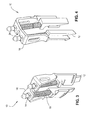
- FIGURES 3 and 4 are perspective views with the guide rods in an extended position
- FIGURES 5 and 6 show the vertical spring wedge installed between the inlet mixer and the adjacent restrainer bracket in a jet pump with the guide rods in the retracted position
- FIGURES 7 and 8 show the vertical spring wedge installed in the gap with the guide rods in the extended position.
- the vertical spring wedge 10 described herein generally includes a pair of tapered wedge segments 12 attached to respective guide rods 14 with pre-load springs 16, all of which are mounted within a U-shaped bracket 18.
- the assembly 10 has a compact configuration to fit within the limited radial space between an inlet mixer 1M and a restrainer bracket RB in a boiling water nuclear reactor jet pump (see FIG. 7).
- the springs 16 are mounted on the guide rods 14 between the bracket 18 and the wedge segment 12. With the guide rods 14 in a retracted position (FIGS. 1 and 2), a pre-load force of the springs acts to drive the guide rods 14 toward an extended position (FIGS. 3 and 4).
- the springs 16 are preferably helical coil springs.
- the spring pre-load provides wedge segment seating force, as was previously provided by the weight of the larger wedge in previous gravity wedge designs. As a result, when the wedge assembly is installed in the nominal aligned position, each spring 1.6 is compressed to provide about six pounds pre-load to force the mating wedge segments 12 into engagement.
- the spring pre-load of the wedge acting across the shallow angled wedge surfaces maintains rigid contact between the inlet mixer and the restrainer bracket. The wedge also takes up the clearance from wear during operation.
- the vertical legs of the bracket 18 include tapered guiding portions 20 as shown in FIG. 2.
- the guiding portions 20 guide and react against the wedge segments 12, wherein the wedge segments 12 and the guiding portions 20 are tangentially offset to minimize a tool radial thickness of the assembly.
- the bracket 18 is open in its center to fit around the existing restrainer bracket set screw and guide ear features, which also maintain the vertical orientation of the wedge 10. Additionally, the bracket 18 has a relief slot 24 at the top that straddles the restrainer bracket guide ear, and projecting lips 28 (FIG. 1) that engage the bottom of the restrainer bracket to further assure that the vertical orientation of the assembly is maintained.
- the wedge segments 12 are machined with a 10° slope angle between their sliding surfaces, which is consistent with the previous gravity wedges described above. This angle has been found by testing and operating experience to provide a tightly sealed fitup that gives a rigid load path between the parts, without being so shallow that friction results in self-locking of the wedge adjusted motion.
- the guiding portions 20 of the bracket 18 preferably include 10° sloped guide slots to which the wedge segments 12 seat against.
- the guide rods 14 are preferably attached to the wedge segments 12 by a threaded engagement, oriented parallel to the 10° wedge surfaces.
- a portion of the upper length of each guide rod 14 has a square cross section and fits within a mating square hole 22 in the top or cross member of the bracket 18.
- the guide rod 14 and wedge segments 12 are locked against rotation at assembly by inserting a pin into a hole drilled in both parts to assure that no parts can become loose.
- the sliding fit between the guide rods 14 and the bracket holes 22 and between the wedge segments 12 and the mating bracket surfaces or guiding portions 20 guide the wedges within the bracket along the 10° sloped axis.
- the sliding fitup also maintains relative alignment of the parts during handling, until the wedge is installed.
- the initial wedge thickness is machined before assembly, based on inspection measurements of the existing set screw protrusion, to assure that the wedge is installed with a useful operating pre-load range.
- the gravity wedges typically weighed S-10 pounds, so an initial twelve pound total spring force on a 10° slope reacts against the projecting lips to allow the wedges to compensate for an increase in the gap of about 0.12 inches while maintaining the minimum pre-load previously used.
- the wedge assembly 10 is installed using a collet tool, which grips the tops of the wedge guide rods 14.
- the tool pulls the guide rods 14 upward against the bracket 18, compressing the springs 16.
- the combined width of the wedge segment 12 and bracket 18 decreases, such as to allow installation clearance in the space between the inlet mixer and the restrainer bracket.
- the assembly is lowered into the restrainer bracket/inlet mixer gap, and the collet tool is released.
- the wedge segments 12 locate against either side of the set screw at installation, keeping the wedge assembly in position.
- the vertical spring wedge described herein restores the tight and rigid fitup originally provided between the inlet mixer and the adjacent restrainer bracket in a boiling water nuclear reactor jet pump, replacing the support function of an existing screw type contact. It provides continuous adjustment for possible alignment variation of the mixer, and compensates for possible wear after installation.
- the device is remotely installable in a clearance width as small as 0.25 inches and requires minimum installation time, without disassembly of the jet pump. It is also configured with a minimum of weight and height to be supported above the engagement between the inlet mixer and the restrainer bracket, which assures that the vibration frequencies of the assembly are enough higher than the jet pump excitation frequencies that resonance and fatigue failure are avoided. Provision of two independently pre-loaded wedges provides tight fitup on both sides of the set screw to compensate for the positioning of the inlet mixer within the restrainer bracket, which is generally not symmetrical.
Landscapes
- Engineering & Computer Science (AREA)
- General Engineering & Computer Science (AREA)
- Mechanical Engineering (AREA)
- Physics & Mathematics (AREA)
- Plasma & Fusion (AREA)
- High Energy & Nuclear Physics (AREA)
- Jet Pumps And Other Pumps (AREA)
- Structures Of Non-Positive Displacement Pumps (AREA)
Abstract
Description
- The invention relates to an apparatus for restoring a tight fitup provided against an adjacent structure and, more particularly, to a compact remotely installable jet pump piping support device that restores the tight and rigid fitup originally provided between the inlet mixer and the adjacent restrainer bracket in a boiling water nuclear reactor jet pump.
- In a boiling water nuclear reactor (BWR), hollow tubular jet pumps positioned within the shroud annulus provide the required reactor core flow. The upper portion (inlet mixer) is laterally positioned and supported against two opposing rigid set screw contacts within restrainer brackets by a gravity actuated wedge, intended to assure clearances do not occur at the supports.
- The flow through and outside the jet pumps contains pressure fluctuations from various sources in the reactor system. The pressure fluctuations can have frequencies close to one or more natural vibration modes of the jet pump piping, which depend on the tight fitup of the restrainer bracket contacts, which support the inlet mixer from the jet pump riser pipe.
- Operating thermal gradients, component alignment changes, hydraulic loads, and fluctuations in these loads can overcome the lateral support provided by the gravity wedge. These effects and/or loosening of the set screws due to failure of their securing tack welds can cause clearances to develop at the opposing two fixed set screw contacts. This loss of contact can change the jet pump natural frequency to match some excitation frequency in the system, causing vibration of the piping and exerting increased loads which have caused cyclic fatigue cracking and wear of the supports and their welded attachments. This can result in degradation from wear and fatigue at additional jet pump structural supports, to a degree which may require plant shutdown.
- The apparatus described herein is intended for BWR/6 reactor designs, where the available installation clearance access can be as small as 0.25 inches in width, and where disassembly of the inlet mixer to allow wedge installation is to be avoided.
- Over the last 19 years, General Electric has designed and installed both gravity and spring actuated wedge supports at locations where clearances have developed in restrainer bracket contacts. The gravity wedges (see, e.g.,
U.S. Patent No. 6,052,425 ) employed a tapered sliding wedge and a fixed bracket mount which engaged the jet pump restrainer bracket. The earlier types of these designs required disassembly of the jet pumps to allow access for their installation, which was an undesirable expense and extension of the reactor outage time. The gravity wedges were applicable to restrainer bracket/inlet mixer gap widths from about 1.0 to 2.0 inches, as space was required for a wedge with sufficient weight to give the required support load. - General Electric also implemented spiral spring actuated wedge repairs (see, e.g.,
U.S. Patent No. 6,490,331 ) for BWR/4 reactor designs, where the available installation clearance access can be as small as 0.60 inches in width, and where disassembly of the inlet mixer to allow wedge installation was avoided. While it was initially intended that this prior design would also be installable in the smaller access space for BWR/6 reactors, without disassembly of the inlet mixers, this proved too difficult. - Another solution which had limited application was to reinforce the welded attachment of the two fixed contacts to the restrainer bracket, then reseat the inlet mixer against the fixed contacts when the jet pump was reassembled.
- In an exemplary embodiment of the invention, a vertical spring wedge restores a tight fitup against an adjacent structure, such as between an inlet mixer and an adjacent restrainer bracket in a boiling water nuclear reactor jet pump. The vertical spring wedge includes a U-shaped bracket including a pair of guiding portions and a pair of bracket holes. A pair of wedge assemblies are coupled with the bracket, each of the wedge assemblies including a wedge segment attached to a spring-loaded guide rod. The guide rods are displaceable in the bracket holes between a retracted position and an extended position. The wedge segments engage the guiding portions, and a combination of the bracket and wedge assemblies have a first width when the guide rods are in the retracted position and have a second width wider than the first width when the guide rods are in the extended position.
- In another exemplary embodiment of the invention, a method of restoring a tight fitup between an inlet mixer and an adjacent restrainer bracket in a boiling water nuclear reactor jet pump includes the steps of pulling the guide rods against the spring-load to the retracted position; inserting the vertical spring wedge into a gap between the inlet mixer and the restrainer bracket; and releasing the guide rods, wherein the spring-load urges the guide rods toward the extended position.
- Embodiments of the present invention will now be described, by way of example only, with reference to the accompanying drawings, in which:
- FIGURES 1 and 2 are perspective views of the vertical spring wedge with the guide rods in a retracted position;
- FIGURES 3 and 4 are perspective views with the guide rods in an extended position;
- FIGURES 5 and 6 show the vertical spring wedge installed between the inlet mixer and the adjacent restrainer bracket in a jet pump with the guide rods in the retracted position; and
- FIGURES 7 and 8 show the vertical spring wedge installed in the gap with the guide rods in the extended position.
- The
vertical spring wedge 10 described herein generally includes a pair oftapered wedge segments 12 attached torespective guide rods 14 withpre-load springs 16, all of which are mounted within aU-shaped bracket 18. Theassembly 10 has a compact configuration to fit within the limited radial space between an inlet mixer 1M and a restrainer bracket RB in a boiling water nuclear reactor jet pump (see FIG. 7). - As shown, the
springs 16 are mounted on theguide rods 14 between thebracket 18 and thewedge segment 12. With theguide rods 14 in a retracted position (FIGS. 1 and 2), a pre-load force of the springs acts to drive theguide rods 14 toward an extended position (FIGS. 3 and 4). - The
springs 16 are preferably helical coil springs. The spring pre-load provides wedge segment seating force, as was previously provided by the weight of the larger wedge in previous gravity wedge designs. As a result, when the wedge assembly is installed in the nominal aligned position, each spring 1.6 is compressed to provide about six pounds pre-load to force themating wedge segments 12 into engagement. The spring pre-load of the wedge acting across the shallow angled wedge surfaces maintains rigid contact between the inlet mixer and the restrainer bracket. The wedge also takes up the clearance from wear during operation. - The vertical legs of the
bracket 18 include tapered guidingportions 20 as shown in FIG. 2. The guidingportions 20 guide and react against thewedge segments 12, wherein thewedge segments 12 and the guidingportions 20 are tangentially offset to minimize a tool radial thickness of the assembly. - With reference to FIGS. 7 and 8, the
bracket 18 is open in its center to fit around the existing restrainer bracket set screw and guide ear features, which also maintain the vertical orientation of thewedge 10. Additionally, thebracket 18 has arelief slot 24 at the top that straddles the restrainer bracket guide ear, and projecting lips 28 (FIG. 1) that engage the bottom of the restrainer bracket to further assure that the vertical orientation of the assembly is maintained. - The
wedge segments 12 are machined with a 10° slope angle between their sliding surfaces, which is consistent with the previous gravity wedges described above. This angle has been found by testing and operating experience to provide a tightly sealed fitup that gives a rigid load path between the parts, without being so shallow that friction results in self-locking of the wedge adjusted motion. The guidingportions 20 of thebracket 18 preferably include 10° sloped guide slots to which the wedge segments 12 seat against. - The
guide rods 14 are preferably attached to thewedge segments 12 by a threaded engagement, oriented parallel to the 10° wedge surfaces. A portion of the upper length of eachguide rod 14 has a square cross section and fits within a matingsquare hole 22 in the top or cross member of thebracket 18. Theguide rod 14 andwedge segments 12 are locked against rotation at assembly by inserting a pin into a hole drilled in both parts to assure that no parts can become loose. - The sliding fit between the
guide rods 14 and thebracket holes 22 and between thewedge segments 12 and the mating bracket surfaces or guidingportions 20 guide the wedges within the bracket along the 10° sloped axis. The sliding fitup also maintains relative alignment of the parts during handling, until the wedge is installed. - From the retracted position as shown in FIGS. 1 and 2, as the wedges are displaced downward by action of the
springs 16, the combined width of the wedge segments andbracket 18 increases to thereby tighten within the space between the inlet mixer and the restrainer bracket. - The initial wedge thickness is machined before assembly, based on inspection measurements of the existing set screw protrusion, to assure that the wedge is installed with a useful operating pre-load range. The gravity wedges typically weighed S-10 pounds, so an initial twelve pound total spring force on a 10° slope reacts against the projecting lips to allow the wedges to compensate for an increase in the gap of about 0.12 inches while maintaining the minimum pre-load previously used.
- Preferably, the
wedge assembly 10 is installed using a collet tool, which grips the tops of thewedge guide rods 14. The tool pulls theguide rods 14 upward against thebracket 18, compressing thesprings 16. As the wedge is displaced upward, the combined width of thewedge segment 12 andbracket 18 decreases, such as to allow installation clearance in the space between the inlet mixer and the restrainer bracket. The assembly is lowered into the restrainer bracket/inlet mixer gap, and the collet tool is released. Thewedge segments 12 locate against either side of the set screw at installation, keeping the wedge assembly in position. - The vertical spring wedge described herein restores the tight and rigid fitup originally provided between the inlet mixer and the adjacent restrainer bracket in a boiling water nuclear reactor jet pump, replacing the support function of an existing screw type contact. It provides continuous adjustment for possible alignment variation of the mixer, and compensates for possible wear after installation. The device is remotely installable in a clearance width as small as 0.25 inches and requires minimum installation time, without disassembly of the jet pump. It is also configured with a minimum of weight and height to be supported above the engagement between the inlet mixer and the restrainer bracket, which assures that the vibration frequencies of the assembly are enough higher than the jet pump excitation frequencies that resonance and fatigue failure are avoided. Provision of two independently pre-loaded wedges provides tight fitup on both sides of the set screw to compensate for the positioning of the inlet mixer within the restrainer bracket, which is generally not symmetrical.
- While the invention has been described in connection with what is presently considered to be the most practical and preferred embodiments, it is to be understood that the invention is not to be limited to the disclosed embodiments, but on the contrary, is intended to cover various modifications and equivalent arrangements included within the spirit and scope of the appended claims.
Claims (12)
- A vertical spring wedge for restoring a tight fitup against an adjacent structure, the vertical spring wedge comprising:a U-shaped bracket (18) including a pair of guiding portions (20) and a pair of bracket holes (22); anda pair of wedge assemblies coupled with the bracket, each of the wedge assemblies including a wedge segment (12) attached to a spring-loaded guide rod (14), the guide rods being displaceable in the bracket holes between a retracted position and an extended position,wherein the wedge segments engage the guiding portions, and wherein a combination of the bracket and wedge assemblies have a first width when the guide rods are in the retracted position and have a second width wider than the first width when the guide rods are in the extended position.
- A vertical spring wedge according to claim 1, wherein the spring-loaded guide rods (14) each comprise a spring (16) secured between the bracket (18) and the wedge segment (12).
- A vertical spring wedge according to claim 2, wherein with the guide rods (14) in the retracted position, a pre-load force of the springs (16) acts to drive the guide rods toward the extended position.
- A vertical spring wedge according to claim 3, wherein the pre-load force for each spring (16) is about 6 lbs.
- A vertical spring wedge according to claim 1, wherein each of the guiding portions (20) comprises a tapered section engageable with the wedge segments (12) such that the wedge segments and the guiding portions are tangentially offset.
- A vertical spring wedge according to claim 1, wherein the wedge segments (12) comprise a slope angle of about 10 degrees.
- A vertical spring wedge according to claim 1, wherein the first width is defined such that the vertical spring wedge is remotely installable in a clearance width as small as 0.25 inches.
- A vertical spring wedge according to claim 1, wherein the tight fitup is between an inlet mixer and an adjacent restrainer bracket in a boiling water nuclear reactor jet pump, and wherein the bracket (18) comprises a relief slot (24) between the bracket holes (22) for accommodating a guide ear of the restrainer bracket.
- A vertical spring wedge according to claim 8, wherein the guiding portions (20) are spaced a sufficient distance to accommodate a set screw of the restrainer bracket.
- A method of restoring a tight fitup between an inlet mixer and an adjacent restrainer bracket in a boiling water nuclear reactor jet pump using the vertical spring wedge of claim 8, the method comprising:pulling the guide rods (14) against the spring-load to the retracted position;inserting the vertical spring wedge (10) into a gap between the inlet mixer and the restrainer bracket; andreleasing the guide rods, wherein the spring-load urges the guide rods toward the extended position.
- A method according to claim 10, wherein the inserting step comprising inserting the vertical spring wedge (10) into the gap until the bracket relief slot (24) surrounds a guide ear of the restrainer bracket.
- A vertical spring wedge for restoring a tight fitup against an adjacent structure, the vertical spring wedge comprising:a U-shaped bracket (18) including bracket legs and a cross member, the bracket comprising a pair of tapered guiding portions (20) on the bracket legs and a pair of bracket holes (22) in the cross member; anda pair of wedge assemblies coupled with the bracket, each of the wedge assemblies including a wedge segment (12) attached to a spring-loaded guide rod (14), the guide rods being displaceable in the bracket holes between a retracted position and an extended position,wherein the wedge segments engage the guiding portions, and wherein a combination of the bracket and wedge assemblies have a first width when the guide rods are in the retracted position and have a second width wider than the first width when the guide rods are in the extended position.
Applications Claiming Priority (1)
| Application Number | Priority Date | Filing Date | Title |
|---|---|---|---|
| US11/585,183 US7627074B2 (en) | 2006-10-24 | 2006-10-24 | Vertical spring wedge |
Publications (2)
| Publication Number | Publication Date |
|---|---|
| EP1916668A1 true EP1916668A1 (en) | 2008-04-30 |
| EP1916668B1 EP1916668B1 (en) | 2009-12-23 |
Family
ID=38913441
Family Applications (1)
| Application Number | Title | Priority Date | Filing Date |
|---|---|---|---|
| EP20070118789 Active EP1916668B1 (en) | 2006-10-24 | 2007-10-18 | Vertical spring wedge |
Country Status (7)
| Country | Link |
|---|---|
| US (1) | US7627074B2 (en) |
| EP (1) | EP1916668B1 (en) |
| JP (1) | JP5607290B2 (en) |
| DE (1) | DE602007003930D1 (en) |
| ES (1) | ES2336038T3 (en) |
| MX (1) | MX2007012424A (en) |
| TW (1) | TWI416542B (en) |
Families Citing this family (9)
| Publication number | Priority date | Publication date | Assignee | Title |
|---|---|---|---|---|
| US8608121B2 (en) * | 2007-07-06 | 2013-12-17 | Kabushiki Kaisha Toshiba | Device and method for fixing a reactor metering pipe |
| US8605852B2 (en) * | 2009-11-09 | 2013-12-10 | Westinghouse Electric Company Llc | Wedge positioning apparatus for jet pump assemblies in nuclear reactors |
| US8197225B2 (en) * | 2010-07-16 | 2012-06-12 | Ge-Hitachi Nuclear Energy Americas Llc | Jet pump slip joint clamps and methods of using the same |
| US8731127B2 (en) * | 2010-08-04 | 2014-05-20 | Ge-Hitachi Nuclear Energy Americas, Llc | Method and apparatus for a BWR inlet mixer clamp assembly |
| US8731134B2 (en) * | 2010-08-06 | 2014-05-20 | Ge-Hitachi Nuclear Energy Americas Llc | Method and apparatus for a BWR jet pump inlet mixer support |
| US8705686B2 (en) * | 2010-12-28 | 2014-04-22 | Ge-Hitachi Nuclear Energy Americas Llc | Adjustable hard stops for nuclear reactor restrainer brackets and methods of using the same |
| US10024338B2 (en) | 2011-05-12 | 2018-07-17 | Ge-Hitachi Nuclear Energy Americas Llc | Method and apparatus for a BWR jet pump inlet mixer compliant stop |
| RU2528398C1 (en) * | 2013-06-18 | 2014-09-20 | Федеральное государственное унитарное предприятие "Горно-химический комбинат" | Device for lifting and transfer of used fuel rod arrays |
| CN117242530A (en) | 2021-04-19 | 2023-12-15 | 霍尔泰克国际公司 | Self-adjusting anti-seismic system for nuclear fuel storage |
Citations (4)
| Publication number | Priority date | Publication date | Assignee | Title |
|---|---|---|---|---|
| US5385320A (en) * | 1993-09-16 | 1995-01-31 | Chieftain Corporation | Hook shaped pipe hanger |
| US6052425A (en) | 1998-12-21 | 2000-04-18 | General Electric Company | Jet pump auxiliary wedge |
| US6490331B2 (en) | 2000-12-28 | 2002-12-03 | General Electric Company | Jet pump spring wedge |
| US20040052325A1 (en) * | 2002-09-13 | 2004-03-18 | General Electric Company | Jet pump set screw wedge |
Family Cites Families (29)
| Publication number | Priority date | Publication date | Assignee | Title |
|---|---|---|---|---|
| US4197652A (en) * | 1978-04-27 | 1980-04-15 | General Electric Company | Plane of reference device |
| BE1005571A3 (en) * | 1991-02-14 | 1993-11-09 | Tilman Paul Louis Joseph | Device for lifting or gap. |
| US5688419A (en) | 1994-04-22 | 1997-11-18 | General Electric Company | Method for mitigating residual stresses in welded metal components using high torch travel speeds |
| US5621778A (en) | 1994-05-19 | 1997-04-15 | General Electric Company | Shroud restraint stabilizer |
| US5742653A (en) | 1994-05-19 | 1998-04-21 | General Electric Company | Vertical and lateral restraint stabilizer for core shroud of boiling water reactor |
| US5521951A (en) | 1994-09-23 | 1996-05-28 | General Electric Company | Reactor core shroud repair with tapered pins |
| US5683216A (en) | 1995-02-02 | 1997-11-04 | General Electric Company | Spring latching mechanisms for preventing relative movement of assembled components |
| US5502754A (en) | 1995-02-02 | 1996-03-26 | General Electric Company | Lateral restraint for core plate of boiling water reactor |
| US5586155A (en) | 1995-02-14 | 1996-12-17 | General Electric Company | Narrow access scanning positioner for inspecting core shroud in boiling water reactor |
| US5838751A (en) | 1996-06-18 | 1998-11-17 | General Electric Company | Core plate repair using guide tube gap wedges |
| US5752807A (en) | 1996-06-26 | 1998-05-19 | General Electric Company | Jet pump sensing line repair |
| US6053652A (en) | 1996-11-20 | 2000-04-25 | General Electric Company | Apparatus for performing jet pump riser pipe repairs |
| US5737379A (en) | 1997-02-21 | 1998-04-07 | General Electric Company | Reactor core shroud repair using thermally tensioned ring to apply compression across shroud vertical seam welds |
| US6067338A (en) | 1997-02-21 | 2000-05-23 | General Electric Company | Reactor core shroud repair using thermally tensioned links to apply compression across shroud vertical seam weld |
| US6236700B1 (en) | 1998-02-25 | 2001-05-22 | General Electric Company | Downcommer coupling apparatus and methods |
| US5978433A (en) * | 1998-12-21 | 1999-11-02 | General Electric Company | Jet pump wedge locking support apparatus |
| US6343107B1 (en) | 2000-02-01 | 2002-01-29 | General Electric Company | Shroud repair apparatus |
| US6394765B1 (en) | 2000-10-18 | 2002-05-28 | General Electric Company | Jet pump slip joint clamp apparatus |
| US6438192B1 (en) | 2000-10-30 | 2002-08-20 | General Electric Company | Jet pump slip joint seal |
| US6450774B1 (en) | 2000-12-21 | 2002-09-17 | General Electric Company | Method and system for a jet pump slip joint ovalization |
| US6434208B1 (en) | 2001-01-31 | 2002-08-13 | General Electric Company | Jet pump beam lock |
| US6587535B1 (en) | 2001-07-10 | 2003-07-01 | General Electric Company | Jet pump slip joint labyrinth seal method |
| US6435839B1 (en) | 2001-11-19 | 2002-08-20 | General Electric Company | Jet pump sensing line clamp assembly and methods |
| JP4097935B2 (en) * | 2001-11-26 | 2008-06-11 | 株式会社東芝 | Jet pump intermediate support device |
| US6932117B2 (en) * | 2002-08-26 | 2005-08-23 | General Electric Company | Reactor water isolation devices |
| US20040190671A1 (en) * | 2003-03-26 | 2004-09-30 | Wivagg Adrian P. | Jet pump assembly repair method |
| ITTO20030366A1 (en) * | 2003-05-20 | 2004-11-21 | Fiat Ricerche | STOP DEVICE WITH SHAPE MEMORY ACTUATOR. |
| JP2004347437A (en) * | 2003-05-22 | 2004-12-09 | Hitachi Ltd | Jet pump wedge mechanism and its replacement method |
| JP2006009902A (en) * | 2004-06-24 | 2006-01-12 | Ishikawajima Harima Heavy Ind Co Ltd | Gap adjustment device |
-
2006
- 2006-10-24 US US11/585,183 patent/US7627074B2/en active Active
-
2007
- 2007-10-05 MX MX2007012424A patent/MX2007012424A/en active IP Right Grant
- 2007-10-10 JP JP2007263926A patent/JP5607290B2/en active Active
- 2007-10-11 TW TW96138006A patent/TWI416542B/en active
- 2007-10-18 EP EP20070118789 patent/EP1916668B1/en active Active
- 2007-10-18 ES ES07118789T patent/ES2336038T3/en active Active
- 2007-10-18 DE DE200760003930 patent/DE602007003930D1/en active Active
Patent Citations (4)
| Publication number | Priority date | Publication date | Assignee | Title |
|---|---|---|---|---|
| US5385320A (en) * | 1993-09-16 | 1995-01-31 | Chieftain Corporation | Hook shaped pipe hanger |
| US6052425A (en) | 1998-12-21 | 2000-04-18 | General Electric Company | Jet pump auxiliary wedge |
| US6490331B2 (en) | 2000-12-28 | 2002-12-03 | General Electric Company | Jet pump spring wedge |
| US20040052325A1 (en) * | 2002-09-13 | 2004-03-18 | General Electric Company | Jet pump set screw wedge |
Also Published As
| Publication number | Publication date |
|---|---|
| JP2008107345A (en) | 2008-05-08 |
| US20080137793A1 (en) | 2008-06-12 |
| DE602007003930D1 (en) | 2010-02-04 |
| TW200836216A (en) | 2008-09-01 |
| EP1916668B1 (en) | 2009-12-23 |
| JP5607290B2 (en) | 2014-10-15 |
| MX2007012424A (en) | 2009-02-03 |
| TWI416542B (en) | 2013-11-21 |
| ES2336038T3 (en) | 2010-04-07 |
| US7627074B2 (en) | 2009-12-01 |
Similar Documents
| Publication | Publication Date | Title |
|---|---|---|
| EP1916668B1 (en) | Vertical spring wedge | |
| EP1014385B1 (en) | Jet pump auxiliary wedge | |
| US5978433A (en) | Jet pump wedge locking support apparatus | |
| JP4119494B2 (en) | Spring locking mechanism for preventing relative movement of assembly components | |
| US6788756B2 (en) | Jet pump set screw wedge | |
| US6490331B2 (en) | Jet pump spring wedge | |
| US20120032064A1 (en) | Method and apparatus for a bwr jet pump support system | |
| US6434208B1 (en) | Jet pump beam lock | |
| US20120170704A1 (en) | Method and apparatus for a jet pump three point slip joint clamp | |
| US6435839B1 (en) | Jet pump sensing line clamp assembly and methods | |
| EP2426671B1 (en) | Method and apparatus for a jet pump slip joint internal seal | |
| EP2400164B1 (en) | Torsional restraint for jet pump assembly | |
| US8731134B2 (en) | Method and apparatus for a BWR jet pump inlet mixer support | |
| JP4340793B2 (en) | Clamping device | |
| US8605852B2 (en) | Wedge positioning apparatus for jet pump assemblies in nuclear reactors | |
| EP2333782B1 (en) | System for restricting the movement of a component | |
| JP2001255394A (en) | Shroud repair equipment | |
| US20110064183A1 (en) | Methods for stabilizing a steam dryer assembly in a nuclear reactor pressure vessel | |
| US20050271182A1 (en) | Method and apparatus for reducing vibration in component of a nuclear reactor |
Legal Events
| Date | Code | Title | Description |
|---|---|---|---|
| PUAI | Public reference made under article 153(3) epc to a published international application that has entered the european phase |
Free format text: ORIGINAL CODE: 0009012 |
|
| AK | Designated contracting states |
Kind code of ref document: A1 Designated state(s): AT BE BG CH CY CZ DE DK EE ES FI FR GB GR HU IE IS IT LI LT LU LV MC MT NL PL PT RO SE SI SK TR |
|
| AX | Request for extension of the european patent |
Extension state: AL BA HR MK RS |
|
| 17P | Request for examination filed |
Effective date: 20081030 |
|
| 17Q | First examination report despatched |
Effective date: 20081201 |
|
| AKX | Designation fees paid |
Designated state(s): CH DE ES FI LI SE |
|
| GRAP | Despatch of communication of intention to grant a patent |
Free format text: ORIGINAL CODE: EPIDOSNIGR1 |
|
| GRAS | Grant fee paid |
Free format text: ORIGINAL CODE: EPIDOSNIGR3 |
|
| GRAA | (expected) grant |
Free format text: ORIGINAL CODE: 0009210 |
|
| AK | Designated contracting states |
Kind code of ref document: B1 Designated state(s): CH DE ES FI LI SE |
|
| REG | Reference to a national code |
Ref country code: CH Ref legal event code: EP |
|
| REG | Reference to a national code |
Ref country code: CH Ref legal event code: NV Representative=s name: SERVOPATENT GMBH |
|
| REF | Corresponds to: |
Ref document number: 602007003930 Country of ref document: DE Date of ref document: 20100204 Kind code of ref document: P |
|
| REG | Reference to a national code |
Ref country code: ES Ref legal event code: FG2A Ref document number: 2336038 Country of ref document: ES Kind code of ref document: T3 |
|
| REG | Reference to a national code |
Ref country code: SE Ref legal event code: TRGR |
|
| PLBE | No opposition filed within time limit |
Free format text: ORIGINAL CODE: 0009261 |
|
| STAA | Information on the status of an ep patent application or granted ep patent |
Free format text: STATUS: NO OPPOSITION FILED WITHIN TIME LIMIT |
|
| 26N | No opposition filed |
Effective date: 20100924 |
|
| PGFP | Annual fee paid to national office [announced via postgrant information from national office to epo] |
Ref country code: FI Payment date: 20180920 Year of fee payment: 12 Ref country code: SE Payment date: 20180924 Year of fee payment: 12 |
|
| PGFP | Annual fee paid to national office [announced via postgrant information from national office to epo] |
Ref country code: DE Payment date: 20180819 Year of fee payment: 12 |
|
| REG | Reference to a national code |
Ref country code: DE Ref legal event code: R119 Ref document number: 602007003930 Country of ref document: DE |
|
| REG | Reference to a national code |
Ref country code: FI Ref legal event code: MAE |
|
| REG | Reference to a national code |
Ref country code: CH Ref legal event code: PCAR Free format text: NEW ADDRESS: WANNERSTRASSE 9/1, 8045 ZUERICH (CH) |
|
| PG25 | Lapsed in a contracting state [announced via postgrant information from national office to epo] |
Ref country code: FI Free format text: LAPSE BECAUSE OF NON-PAYMENT OF DUE FEES Effective date: 20191018 Ref country code: DE Free format text: LAPSE BECAUSE OF NON-PAYMENT OF DUE FEES Effective date: 20200501 |
|
| PG25 | Lapsed in a contracting state [announced via postgrant information from national office to epo] |
Ref country code: SE Free format text: LAPSE BECAUSE OF NON-PAYMENT OF DUE FEES Effective date: 20191019 |
|
| REG | Reference to a national code |
Ref country code: ES Ref legal event code: PC2A Owner name: GE HITACHI NUCLEAR ENERGY AMERICAS LLC Effective date: 20240709 |
|
| REG | Reference to a national code |
Ref country code: CH Ref legal event code: U11 Free format text: ST27 STATUS EVENT CODE: U-0-0-U10-U11 (AS PROVIDED BY THE NATIONAL OFFICE) Effective date: 20251101 |
|
| PGFP | Annual fee paid to national office [announced via postgrant information from national office to epo] |
Ref country code: CH Payment date: 20251101 Year of fee payment: 19 |
|
| PGFP | Annual fee paid to national office [announced via postgrant information from national office to epo] |
Ref country code: ES Payment date: 20251103 Year of fee payment: 19 |