EP1916433A1 - Friction Clutch and Sunblind Drive - Google Patents
Friction Clutch and Sunblind Drive Download PDFInfo
- Publication number
- EP1916433A1 EP1916433A1 EP06301085A EP06301085A EP1916433A1 EP 1916433 A1 EP1916433 A1 EP 1916433A1 EP 06301085 A EP06301085 A EP 06301085A EP 06301085 A EP06301085 A EP 06301085A EP 1916433 A1 EP1916433 A1 EP 1916433A1
- Authority
- EP
- European Patent Office
- Prior art keywords
- disk
- friction clutch
- shaft
- sunblind
- disks
- Prior art date
- Legal status (The legal status is an assumption and is not a legal conclusion. Google has not performed a legal analysis and makes no representation as to the accuracy of the status listed.)
- Granted
Links
Images
Classifications
-
- F—MECHANICAL ENGINEERING; LIGHTING; HEATING; WEAPONS; BLASTING
- F16—ENGINEERING ELEMENTS AND UNITS; GENERAL MEASURES FOR PRODUCING AND MAINTAINING EFFECTIVE FUNCTIONING OF MACHINES OR INSTALLATIONS; THERMAL INSULATION IN GENERAL
- F16D—COUPLINGS FOR TRANSMITTING ROTATION; CLUTCHES; BRAKES
- F16D7/00—Slip couplings, e.g. slipping on overload, for absorbing shock
- F16D7/02—Slip couplings, e.g. slipping on overload, for absorbing shock of the friction type
- F16D7/022—Slip couplings, e.g. slipping on overload, for absorbing shock of the friction type with a helical band or equivalent member co-operating with a cylindrical torque limiting coupling surface
Definitions
- the invention relates to a friction clutch for coupling a first shaft or disk to a second shaft or disk with limited moment of force according to the preamble of claim 1, as well as to a sunblind drive according to the preamble of claim 4.
- each cam plate has one notch for activating a switch.
- the cam plates and switches are arranged such that a switch will only be activated, when the notches of two assigned cam plates synchronously allow the switch to activate.
- the cam plates are driven by one-stage gears, the inputs of which are driven by the sunblind drive.
- the two gears belonging together are different to the effect that only after 70 revolutions of one of the disks both notches again have the same positions. These 70 revolutions correspond to the maximum length of the sunblind.
- the switches shall be driven only by the gears. That means that during normal operation the cam plates shall be fixed to the gears, while when adjusting such fixed fastening shall be overridden manually. This is done by interconnected friction clutches.
- the friction clutches used hitherto suffer from not providing exact concentricity.
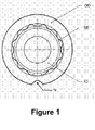
- Figure 1 shows an inner disk ID, an outer disk OD, and a springy element SE in between.
- the outer disk OD carries a notch N.
- the inner disk ID has an outer diameter of some 12.5 mm and is about 4 mm thick. It extents from a wheel that is a guidance also for the outer disk OD.
- This outer disk OD has an inner diameter of some 14 mm and also is about 4 mm thick. So the gap between the two disks lies in the range of 0.7 mm.
- the springy element SE in this example is made of a springy sheet metal with some 0.3 mm thickness. It is corrugated such that it meanders between the two disks more or less along the whole circumference of this gap. So in principle it behaves as a number of like springs equally distributed along the whole circumference of this gap.
- the springy element When the springy element is made of a springy sheet metal, as in this example, it cannot tilt, but in principle it could migrate. In the given example this is hindered in one direction by the wheel from which the inner disk ID extends and in the other direction by the next friction clutch.
- the springy element is very small and in principle could be replaced also by a springy element made out of a spring wire.
- a wire in principle could tilt, a narrower kind of guidance would be recommended, for example small rills both in the inner surface of the outer disk OD and in the outer surface of the inner disk ID.
- the springy element of course could be made also from another springy material like plastics. Also for the disks or shafts any appropriate material could be used.
Landscapes
- Engineering & Computer Science (AREA)
- General Engineering & Computer Science (AREA)
- Mechanical Engineering (AREA)
- Mechanical Operated Clutches (AREA)
- Pharmaceuticals Containing Other Organic And Inorganic Compounds (AREA)
- Blinds (AREA)
Abstract
Description
- The invention relates to a friction clutch for coupling a first shaft or disk to a second shaft or disk with limited moment of force according to the preamble of claim 1, as well as to a sunblind drive according to the preamble of claim 4.
- The invention has been made in connection with sunblind drives. In order to be more demonstrative, the problem will be described with reference to such drives. As it will become apparent, that similar problems occur also in other connection, it is clear, that also the solution found can be used in other connection.
- With the sunblind drives forming the basis for this invention there are four cam plates for activating two end position switches at the upper and lower end position. Each cam plate has one notch for activating a switch. The cam plates and switches are arranged such that a switch will only be activated, when the notches of two assigned cam plates synchronously allow the switch to activate. The cam plates are driven by one-stage gears, the inputs of which are driven by the sunblind drive. The two gears belonging together are different to the effect that only after 70 revolutions of one of the disks both notches again have the same positions. These 70 revolutions correspond to the maximum length of the sunblind.
- When adjusting the end position switches the sunblind is driven to the respective end position and stopped there manually. In doing so the respective outer cam plates are fixed using a slide such that the cams coincide exactly. In this situation the outer cam plates are not driven by the gears, whereas the inner cam plates are driven by the gears. This is affected by the friction clutch. When the wanted end position is reached, the drive is stopped manually (e.g. by hand cable) and the end position is set as soon as the rotational direction is changed. Thereby the fixing of the outer cam plates disengages and they too will be driven again by the gears.
- Afterwards the switches shall be driven only by the gears. That means that during normal operation the cam plates shall be fixed to the gears, while when adjusting such fixed fastening shall be overridden manually. This is done by interconnected friction clutches.
- The friction clutches used hitherto suffer from not providing exact concentricity.
- This problem according to the invention is solved by a friction clutch according to the teaching of claim 1 and a sunblind drive according to the teaching of claim 4.
- With such a friction clutch a number of springs is arranged equally between the two disks or shafts.
- Further embodiments of the invention are to be found in the subclaims and the enclosed description.
- In the following the invention will be described with reference to the accompanying drawing:
- Figure 1
- shows a friction clutch according to the invention for a sunblind drive according to the invention.
- Based on figure 1 a friction clutch according to the invention for a sunblind drive according to the invention now will be described in more detail.
- Figure 1 shows an inner disk ID, an outer disk OD, and a springy element SE in between. The outer disk OD carries a notch N.
- In the given example the inner disk ID has an outer diameter of some 12.5 mm and is about 4 mm thick. It extents from a wheel that is a guidance also for the outer disk OD. This outer disk OD has an inner diameter of some 14 mm and also is about 4 mm thick. So the gap between the two disks lies in the range of 0.7 mm. The springy element SE in this example is made of a springy sheet metal with some 0.3 mm thickness. It is corrugated such that it meanders between the two disks more or less along the whole circumference of this gap. So in principle it behaves as a number of like springs equally distributed along the whole circumference of this gap.
- When the springy element is made of a springy sheet metal, as in this example, it cannot tilt, but in principle it could migrate. In the given example this is hindered in one direction by the wheel from which the inner disk ID extends and in the other direction by the next friction clutch.
- In this example the springy element is very small and in principle could be replaced also by a springy element made out of a spring wire. As a wire in principle could tilt, a narrower kind of guidance would be recommended, for example small rills both in the inner surface of the outer disk OD and in the outer surface of the inner disk ID.
- It is clear that such solution could be used also as a friction clutch between the outer surface of a shaft and the inner surface of a hollow shaft or between a shaft and a disk.
- The springy element of course could be made also from another springy material like plastics. Also for the disks or shafts any appropriate material could be used.
- Of course instead of one springy element also two or more could be used, where each of them only covers part of the circumference.
Claims (4)
- Friction clutch for coupling a first shaft or disk (ID) to a second shaft or disk (OD) with limited moment of force, where the shafts or disks (ID, OD) are arranged within one another in a coaxial manner, including a springy element (SE) connecting both shafts or disks, characterized in, that the springy element (SE) is located between the first shaft or disk (ID) and the second shaft or disk (OD) and appears as corrugated line in a section plane lying perpendicular to the common axis and capturing almost the whole circumference.
- Friction clutch according to claim 1, characterized in, that the springy element (SE) is a springy sheet metal corrugated in the direction of the common axis.
- Friction clutch according to claim 1, characterized in, that the springy element is a spring wire.
- Sunblind drive with at least one cam plate for actuating a switching function, characterized in, that the cam plate is connected to the drive via a friction clutch according to claim 1.
Priority Applications (3)
| Application Number | Priority Date | Filing Date | Title |
|---|---|---|---|
| AT06301085T ATE461376T1 (en) | 2006-10-24 | 2006-10-24 | FRICTION CLUTCH AND BLIND DRIVE |
| EP06301085A EP1916433B1 (en) | 2006-10-24 | 2006-10-24 | Friction Clutch and Sunblind Drive |
| DE602006012993T DE602006012993D1 (en) | 2006-10-24 | 2006-10-24 | Friction clutch and Venetian blind drive |
Applications Claiming Priority (1)
| Application Number | Priority Date | Filing Date | Title |
|---|---|---|---|
| EP06301085A EP1916433B1 (en) | 2006-10-24 | 2006-10-24 | Friction Clutch and Sunblind Drive |
Publications (2)
| Publication Number | Publication Date |
|---|---|
| EP1916433A1 true EP1916433A1 (en) | 2008-04-30 |
| EP1916433B1 EP1916433B1 (en) | 2010-03-17 |
Family
ID=37846852
Family Applications (1)
| Application Number | Title | Priority Date | Filing Date |
|---|---|---|---|
| EP06301085A Active EP1916433B1 (en) | 2006-10-24 | 2006-10-24 | Friction Clutch and Sunblind Drive |
Country Status (3)
| Country | Link |
|---|---|
| EP (1) | EP1916433B1 (en) |
| AT (1) | ATE461376T1 (en) |
| DE (1) | DE602006012993D1 (en) |
Cited By (1)
| Publication number | Priority date | Publication date | Assignee | Title |
|---|---|---|---|---|
| CN102734345A (en) * | 2012-07-18 | 2012-10-17 | 德恩科电机(太仓)有限公司 | Friction clutch and blind window driving mechanism |
Citations (7)
| Publication number | Priority date | Publication date | Assignee | Title |
|---|---|---|---|---|
| GB1014113A (en) * | 1963-11-27 | 1965-12-22 | Rover Co Ltd | Torque-transmitting means permitting relative radial expansion and contraction between a pair of coaxial driven and driving members |
| US3363478A (en) * | 1964-08-19 | 1968-01-16 | Corning Glass Works | Driving means for rotary heat exchangers |
| GB1476872A (en) * | 1974-03-15 | 1977-06-16 | Gross H | Drive mechanism for vertical sun control strips |
| FR2556427A1 (en) * | 1983-12-09 | 1985-06-14 | Klein Schanzlin & Becker Ag | Locking ring for securing boss to spindle |
| EP1201951A1 (en) * | 2000-10-27 | 2002-05-02 | Zurfluh Feller | Roller shutter with driving device actuated by rotation and coil spring torque limiting means |
| WO2003029680A1 (en) * | 2001-09-22 | 2003-04-10 | Valeo Motoren Und Aktuatoren Gmbh | Drive unit comprising a coil-spring braking mechanism |
| EP1630436A2 (en) * | 2004-08-26 | 2006-03-01 | American Axle & Manufacturing, Inc. | Driveshaft assembly with torque ring coupling |
-
2006
- 2006-10-24 EP EP06301085A patent/EP1916433B1/en active Active
- 2006-10-24 DE DE602006012993T patent/DE602006012993D1/en active Active
- 2006-10-24 AT AT06301085T patent/ATE461376T1/en active
Patent Citations (7)
| Publication number | Priority date | Publication date | Assignee | Title |
|---|---|---|---|---|
| GB1014113A (en) * | 1963-11-27 | 1965-12-22 | Rover Co Ltd | Torque-transmitting means permitting relative radial expansion and contraction between a pair of coaxial driven and driving members |
| US3363478A (en) * | 1964-08-19 | 1968-01-16 | Corning Glass Works | Driving means for rotary heat exchangers |
| GB1476872A (en) * | 1974-03-15 | 1977-06-16 | Gross H | Drive mechanism for vertical sun control strips |
| FR2556427A1 (en) * | 1983-12-09 | 1985-06-14 | Klein Schanzlin & Becker Ag | Locking ring for securing boss to spindle |
| EP1201951A1 (en) * | 2000-10-27 | 2002-05-02 | Zurfluh Feller | Roller shutter with driving device actuated by rotation and coil spring torque limiting means |
| WO2003029680A1 (en) * | 2001-09-22 | 2003-04-10 | Valeo Motoren Und Aktuatoren Gmbh | Drive unit comprising a coil-spring braking mechanism |
| EP1630436A2 (en) * | 2004-08-26 | 2006-03-01 | American Axle & Manufacturing, Inc. | Driveshaft assembly with torque ring coupling |
Cited By (1)
| Publication number | Priority date | Publication date | Assignee | Title |
|---|---|---|---|---|
| CN102734345A (en) * | 2012-07-18 | 2012-10-17 | 德恩科电机(太仓)有限公司 | Friction clutch and blind window driving mechanism |
Also Published As
| Publication number | Publication date |
|---|---|
| DE602006012993D1 (en) | 2010-04-29 |
| EP1916433B1 (en) | 2010-03-17 |
| ATE461376T1 (en) | 2010-04-15 |
Similar Documents
| Publication | Publication Date | Title |
|---|---|---|
| EP3191333B2 (en) | Hybrid module comprising a disconnect clutch and a main clutch and actuating system arranged therebetween | |
| EP1912014A3 (en) | Display base including torque limiter and torque limiter | |
| DE10155458A1 (en) | Clutch unit is for torque transmission between engine and gear, and contains a rotary vibration damper and at least one friction coupling | |
| DE4216912C2 (en) | Slip clutch | |
| KR20150101402A (en) | Spring assembly, clutch, and clutch production method | |
| KR20150143744A (en) | Shift collar assembly for a power transfer unit | |
| DE102011085836A1 (en) | Friction clutch with adjuster | |
| WO2007107138A1 (en) | Torque transmitting device which permits a radial displacement, and a clutch plate | |
| EP1916433A1 (en) | Friction Clutch and Sunblind Drive | |
| CN105051427B (en) | Actuator device for motor vehicle transmission and corresponding motor vehicle transmission | |
| CN110268183A (en) | Devices and transmissions for moving shifting elements | |
| US9350214B2 (en) | Actuator | |
| DE3505613C2 (en) | ||
| CN103256316A (en) | Lamella switching element | |
| EP3088755B1 (en) | A powertrain mechanism with drive plate | |
| JP4272883B2 (en) | Transmission element for transmitting torque without play | |
| EP3253981B1 (en) | Friction clutch with wear compensation | |
| DE112007001974B4 (en) | Clutch disc with keyhole-like slots | |
| DE102013201660A1 (en) | Coupling system for powertrain of motor car, has force limiting elasticity parts provided between clutch actuators and pressing plates, and partial path formed between two operating points in specified condition of friction linings | |
| US8701850B2 (en) | Assembly structure of friction device for automatic transmission | |
| EP3264433A1 (en) | Overload clutch for medium voltage switchgears and kinematic chain arrangement for medium voltage switchgears | |
| DE102009005742A1 (en) | Friction clutch for use in double clutch, has sensor spring with worm gear having post adjustable distance from sensor spring to ramp system, where worm gear has external tooth system with teeth arranged in serrated manner | |
| CN110486519B (en) | Actuator and method for setting an actuator | |
| CN113383177B (en) | Dual clutch transmission for electric vehicle and drive unit for electric vehicle | |
| DE102015224910B4 (en) | Torque transmission device |
Legal Events
| Date | Code | Title | Description |
|---|---|---|---|
| PUAI | Public reference made under article 153(3) epc to a published international application that has entered the european phase |
Free format text: ORIGINAL CODE: 0009012 |
|
| 17P | Request for examination filed |
Effective date: 20070717 |
|
| AK | Designated contracting states |
Kind code of ref document: A1 Designated state(s): AT BE BG CH CY CZ DE DK EE ES FI FR GB GR HU IE IS IT LI LT LU LV MC NL PL PT RO SE SI SK TR |
|
| AX | Request for extension of the european patent |
Extension state: AL BA HR MK RS |
|
| 17Q | First examination report despatched |
Effective date: 20080903 |
|
| AKX | Designation fees paid |
Designated state(s): AT BE BG CH CY CZ DE DK EE ES FI FR GB GR HU IE IS IT LI LT LU LV MC NL PL PT RO SE SI SK TR |
|
| AXX | Extension fees paid |
Extension state: RS Payment date: 20081030 Extension state: BA Payment date: 20081030 Extension state: AL Payment date: 20081030 Extension state: MK Payment date: 20081030 Extension state: HR Payment date: 20081030 |
|
| GRAP | Despatch of communication of intention to grant a patent |
Free format text: ORIGINAL CODE: EPIDOSNIGR1 |
|
| GRAS | Grant fee paid |
Free format text: ORIGINAL CODE: EPIDOSNIGR3 |
|
| GRAA | (expected) grant |
Free format text: ORIGINAL CODE: 0009210 |
|
| AK | Designated contracting states |
Kind code of ref document: B1 Designated state(s): AT BE BG CH CY CZ DE DK EE ES FI FR GB GR HU IE IS IT LI LT LU LV MC NL PL PT RO SE SI SK TR |
|
| AX | Request for extension of the european patent |
Extension state: AL BA HR MK RS |
|
| REG | Reference to a national code |
Ref country code: GB Ref legal event code: FG4D |
|
| REG | Reference to a national code |
Ref country code: CH Ref legal event code: NV Representative=s name: TROESCH SCHEIDEGGER WERNER AG Ref country code: CH Ref legal event code: EP |
|
| REG | Reference to a national code |
Ref country code: IE Ref legal event code: FG4D |
|
| REF | Corresponds to: |
Ref document number: 602006012993 Country of ref document: DE Date of ref document: 20100429 Kind code of ref document: P |
|
| REG | Reference to a national code |
Ref country code: SE Ref legal event code: TRGR |
|
| REG | Reference to a national code |
Ref country code: NL Ref legal event code: T3 |
|
| PG25 | Lapsed in a contracting state [announced via postgrant information from national office to epo] |
Ref country code: LT Free format text: LAPSE BECAUSE OF FAILURE TO SUBMIT A TRANSLATION OF THE DESCRIPTION OR TO PAY THE FEE WITHIN THE PRESCRIBED TIME-LIMIT Effective date: 20100317 |
|
| LTIE | Lt: invalidation of european patent or patent extension |
Effective date: 20100317 |
|
| PG25 | Lapsed in a contracting state [announced via postgrant information from national office to epo] |
Ref country code: LV Free format text: LAPSE BECAUSE OF FAILURE TO SUBMIT A TRANSLATION OF THE DESCRIPTION OR TO PAY THE FEE WITHIN THE PRESCRIBED TIME-LIMIT Effective date: 20100317 Ref country code: FI Free format text: LAPSE BECAUSE OF FAILURE TO SUBMIT A TRANSLATION OF THE DESCRIPTION OR TO PAY THE FEE WITHIN THE PRESCRIBED TIME-LIMIT Effective date: 20100317 Ref country code: SI Free format text: LAPSE BECAUSE OF FAILURE TO SUBMIT A TRANSLATION OF THE DESCRIPTION OR TO PAY THE FEE WITHIN THE PRESCRIBED TIME-LIMIT Effective date: 20100317 Ref country code: PL Free format text: LAPSE BECAUSE OF FAILURE TO SUBMIT A TRANSLATION OF THE DESCRIPTION OR TO PAY THE FEE WITHIN THE PRESCRIBED TIME-LIMIT Effective date: 20100317 |
|
| PG25 | Lapsed in a contracting state [announced via postgrant information from national office to epo] |
Ref country code: GR Free format text: LAPSE BECAUSE OF FAILURE TO SUBMIT A TRANSLATION OF THE DESCRIPTION OR TO PAY THE FEE WITHIN THE PRESCRIBED TIME-LIMIT Effective date: 20100618 Ref country code: ES Free format text: LAPSE BECAUSE OF FAILURE TO SUBMIT A TRANSLATION OF THE DESCRIPTION OR TO PAY THE FEE WITHIN THE PRESCRIBED TIME-LIMIT Effective date: 20100628 Ref country code: BE Free format text: LAPSE BECAUSE OF FAILURE TO SUBMIT A TRANSLATION OF THE DESCRIPTION OR TO PAY THE FEE WITHIN THE PRESCRIBED TIME-LIMIT Effective date: 20100317 Ref country code: CY Free format text: LAPSE BECAUSE OF FAILURE TO SUBMIT A TRANSLATION OF THE DESCRIPTION OR TO PAY THE FEE WITHIN THE PRESCRIBED TIME-LIMIT Effective date: 20100317 Ref country code: EE Free format text: LAPSE BECAUSE OF FAILURE TO SUBMIT A TRANSLATION OF THE DESCRIPTION OR TO PAY THE FEE WITHIN THE PRESCRIBED TIME-LIMIT Effective date: 20100317 Ref country code: RO Free format text: LAPSE BECAUSE OF FAILURE TO SUBMIT A TRANSLATION OF THE DESCRIPTION OR TO PAY THE FEE WITHIN THE PRESCRIBED TIME-LIMIT Effective date: 20100317 |
|
| PG25 | Lapsed in a contracting state [announced via postgrant information from national office to epo] |
Ref country code: CZ Free format text: LAPSE BECAUSE OF FAILURE TO SUBMIT A TRANSLATION OF THE DESCRIPTION OR TO PAY THE FEE WITHIN THE PRESCRIBED TIME-LIMIT Effective date: 20100317 Ref country code: SK Free format text: LAPSE BECAUSE OF FAILURE TO SUBMIT A TRANSLATION OF THE DESCRIPTION OR TO PAY THE FEE WITHIN THE PRESCRIBED TIME-LIMIT Effective date: 20100317 Ref country code: BG Free format text: LAPSE BECAUSE OF FAILURE TO SUBMIT A TRANSLATION OF THE DESCRIPTION OR TO PAY THE FEE WITHIN THE PRESCRIBED TIME-LIMIT Effective date: 20100617 Ref country code: IS Free format text: LAPSE BECAUSE OF FAILURE TO SUBMIT A TRANSLATION OF THE DESCRIPTION OR TO PAY THE FEE WITHIN THE PRESCRIBED TIME-LIMIT Effective date: 20100717 |
|
| PLBE | No opposition filed within time limit |
Free format text: ORIGINAL CODE: 0009261 |
|
| STAA | Information on the status of an ep patent application or granted ep patent |
Free format text: STATUS: NO OPPOSITION FILED WITHIN TIME LIMIT |
|
| PG25 | Lapsed in a contracting state [announced via postgrant information from national office to epo] |
Ref country code: DK Free format text: LAPSE BECAUSE OF FAILURE TO SUBMIT A TRANSLATION OF THE DESCRIPTION OR TO PAY THE FEE WITHIN THE PRESCRIBED TIME-LIMIT Effective date: 20100317 Ref country code: PT Free format text: LAPSE BECAUSE OF FAILURE TO SUBMIT A TRANSLATION OF THE DESCRIPTION OR TO PAY THE FEE WITHIN THE PRESCRIBED TIME-LIMIT Effective date: 20100719 |
|
| 26N | No opposition filed |
Effective date: 20101220 |
|
| PGFP | Annual fee paid to national office [announced via postgrant information from national office to epo] |
Ref country code: IE Payment date: 20110209 Year of fee payment: 5 |
|
| PG25 | Lapsed in a contracting state [announced via postgrant information from national office to epo] |
Ref country code: MC Free format text: LAPSE BECAUSE OF NON-PAYMENT OF DUE FEES Effective date: 20101031 |
|
| GBPC | Gb: european patent ceased through non-payment of renewal fee |
Effective date: 20101024 |
|
| PG25 | Lapsed in a contracting state [announced via postgrant information from national office to epo] |
Ref country code: FR Free format text: LAPSE BECAUSE OF NON-PAYMENT OF DUE FEES Effective date: 20101102 |
|
| REG | Reference to a national code |
Ref country code: FR Ref legal event code: ST Effective date: 20110630 |
|
| PG25 | Lapsed in a contracting state [announced via postgrant information from national office to epo] |
Ref country code: GB Free format text: LAPSE BECAUSE OF NON-PAYMENT OF DUE FEES Effective date: 20101024 |
|
| REG | Reference to a national code |
Ref country code: IE Ref legal event code: MM4A |
|
| PG25 | Lapsed in a contracting state [announced via postgrant information from national office to epo] |
Ref country code: LU Free format text: LAPSE BECAUSE OF NON-PAYMENT OF DUE FEES Effective date: 20101024 Ref country code: HU Free format text: LAPSE BECAUSE OF FAILURE TO SUBMIT A TRANSLATION OF THE DESCRIPTION OR TO PAY THE FEE WITHIN THE PRESCRIBED TIME-LIMIT Effective date: 20100918 |
|
| PG25 | Lapsed in a contracting state [announced via postgrant information from national office to epo] |
Ref country code: TR Free format text: LAPSE BECAUSE OF FAILURE TO SUBMIT A TRANSLATION OF THE DESCRIPTION OR TO PAY THE FEE WITHIN THE PRESCRIBED TIME-LIMIT Effective date: 20100317 Ref country code: IE Free format text: LAPSE BECAUSE OF NON-PAYMENT OF DUE FEES Effective date: 20111024 |
|
| PGFP | Annual fee paid to national office [announced via postgrant information from national office to epo] |
Ref country code: NL Payment date: 20181022 Year of fee payment: 13 |
|
| PGFP | Annual fee paid to national office [announced via postgrant information from national office to epo] |
Ref country code: SE Payment date: 20181025 Year of fee payment: 13 |
|
| REG | Reference to a national code |
Ref country code: NL Ref legal event code: MM Effective date: 20191101 |
|
| PG25 | Lapsed in a contracting state [announced via postgrant information from national office to epo] |
Ref country code: SE Free format text: LAPSE BECAUSE OF NON-PAYMENT OF DUE FEES Effective date: 20191025 Ref country code: NL Free format text: LAPSE BECAUSE OF NON-PAYMENT OF DUE FEES Effective date: 20191101 |
|
| PGFP | Annual fee paid to national office [announced via postgrant information from national office to epo] |
Ref country code: IT Payment date: 20221031 Year of fee payment: 17 Ref country code: AT Payment date: 20221018 Year of fee payment: 17 |
|
| PGFP | Annual fee paid to national office [announced via postgrant information from national office to epo] |
Ref country code: CH Payment date: 20221027 Year of fee payment: 17 |
|
| P01 | Opt-out of the competence of the unified patent court (upc) registered |
Effective date: 20230508 |
|
| PGFP | Annual fee paid to national office [announced via postgrant information from national office to epo] |
Ref country code: DE Payment date: 20231207 Year of fee payment: 18 |
|
| REG | Reference to a national code |
Ref country code: CH Ref legal event code: PL |
|
| REG | Reference to a national code |
Ref country code: AT Ref legal event code: MM01 Ref document number: 461376 Country of ref document: AT Kind code of ref document: T Effective date: 20231024 |
|
| PG25 | Lapsed in a contracting state [announced via postgrant information from national office to epo] |
Ref country code: CH Free format text: LAPSE BECAUSE OF NON-PAYMENT OF DUE FEES Effective date: 20231031 |
|
| PG25 | Lapsed in a contracting state [announced via postgrant information from national office to epo] |
Ref country code: AT Free format text: LAPSE BECAUSE OF NON-PAYMENT OF DUE FEES Effective date: 20231024 |
|
| PG25 | Lapsed in a contracting state [announced via postgrant information from national office to epo] |
Ref country code: CH Free format text: LAPSE BECAUSE OF NON-PAYMENT OF DUE FEES Effective date: 20231031 Ref country code: AT Free format text: LAPSE BECAUSE OF NON-PAYMENT OF DUE FEES Effective date: 20231024 |
|
| PG25 | Lapsed in a contracting state [announced via postgrant information from national office to epo] |
Ref country code: IT Free format text: LAPSE BECAUSE OF NON-PAYMENT OF DUE FEES Effective date: 20231024 |
|
| PG25 | Lapsed in a contracting state [announced via postgrant information from national office to epo] |
Ref country code: IT Free format text: LAPSE BECAUSE OF NON-PAYMENT OF DUE FEES Effective date: 20231024 |
|
| REG | Reference to a national code |
Ref country code: DE Ref legal event code: R119 Ref document number: 602006012993 Country of ref document: DE |
|
| PG25 | Lapsed in a contracting state [announced via postgrant information from national office to epo] |
Ref country code: DE Free format text: LAPSE BECAUSE OF NON-PAYMENT OF DUE FEES Effective date: 20250501 |