EP1914476B1 - Differentiated distributor, suitable for premixed gas burners - Google Patents
Differentiated distributor, suitable for premixed gas burners Download PDFInfo
- Publication number
- EP1914476B1 EP1914476B1 EP07019532.6A EP07019532A EP1914476B1 EP 1914476 B1 EP1914476 B1 EP 1914476B1 EP 07019532 A EP07019532 A EP 07019532A EP 1914476 B1 EP1914476 B1 EP 1914476B1
- Authority
- EP
- European Patent Office
- Prior art keywords
- tubular body
- distributor
- zones
- deflector
- premixed gas
- Prior art date
- Legal status (The legal status is an assumption and is not a legal conclusion. Google has not performed a legal analysis and makes no representation as to the accuracy of the status listed.)
- Active
Links
Images


Classifications
-
- F—MECHANICAL ENGINEERING; LIGHTING; HEATING; WEAPONS; BLASTING
- F23—COMBUSTION APPARATUS; COMBUSTION PROCESSES
- F23D—BURNERS
- F23D14/00—Burners for combustion of a gas, e.g. of a gas stored under pressure as a liquid
- F23D14/46—Details
- F23D14/62—Mixing devices; Mixing tubes
-
- F—MECHANICAL ENGINEERING; LIGHTING; HEATING; WEAPONS; BLASTING
- F23—COMBUSTION APPARATUS; COMBUSTION PROCESSES
- F23D—BURNERS
- F23D14/00—Burners for combustion of a gas, e.g. of a gas stored under pressure as a liquid
- F23D14/02—Premix gas burners, i.e. in which gaseous fuel is mixed with combustion air upstream of the combustion zone
- F23D14/04—Premix gas burners, i.e. in which gaseous fuel is mixed with combustion air upstream of the combustion zone induction type, e.g. Bunsen burner
- F23D14/06—Premix gas burners, i.e. in which gaseous fuel is mixed with combustion air upstream of the combustion zone induction type, e.g. Bunsen burner with radial outlets at the burner head
-
- F—MECHANICAL ENGINEERING; LIGHTING; HEATING; WEAPONS; BLASTING
- F23—COMBUSTION APPARATUS; COMBUSTION PROCESSES
- F23D—BURNERS
- F23D14/00—Burners for combustion of a gas, e.g. of a gas stored under pressure as a liquid
- F23D14/02—Premix gas burners, i.e. in which gaseous fuel is mixed with combustion air upstream of the combustion zone
- F23D14/04—Premix gas burners, i.e. in which gaseous fuel is mixed with combustion air upstream of the combustion zone induction type, e.g. Bunsen burner
- F23D14/10—Premix gas burners, i.e. in which gaseous fuel is mixed with combustion air upstream of the combustion zone induction type, e.g. Bunsen burner with elongated tubular burner head
-
- F—MECHANICAL ENGINEERING; LIGHTING; HEATING; WEAPONS; BLASTING
- F23—COMBUSTION APPARATUS; COMBUSTION PROCESSES
- F23D—BURNERS
- F23D14/00—Burners for combustion of a gas, e.g. of a gas stored under pressure as a liquid
- F23D14/46—Details
- F23D14/48—Nozzles
- F23D14/58—Nozzles characterised by the shape or arrangement of the outlet or outlets from the nozzle, e.g. of annular configuration
-
- F—MECHANICAL ENGINEERING; LIGHTING; HEATING; WEAPONS; BLASTING
- F23—COMBUSTION APPARATUS; COMBUSTION PROCESSES
- F23D—BURNERS
- F23D14/00—Burners for combustion of a gas, e.g. of a gas stored under pressure as a liquid
- F23D14/46—Details
- F23D14/70—Baffles or like flow-disturbing devices
-
- F—MECHANICAL ENGINEERING; LIGHTING; HEATING; WEAPONS; BLASTING
- F23—COMBUSTION APPARATUS; COMBUSTION PROCESSES
- F23D—BURNERS
- F23D2203/00—Gaseous fuel burners
- F23D2203/10—Flame diffusing means
- F23D2203/101—Flame diffusing means characterised by surface shape
- F23D2203/1012—Flame diffusing means characterised by surface shape tubular
-
- F—MECHANICAL ENGINEERING; LIGHTING; HEATING; WEAPONS; BLASTING
- F23—COMBUSTION APPARATUS; COMBUSTION PROCESSES
- F23D—BURNERS
- F23D2203/00—Gaseous fuel burners
- F23D2203/10—Flame diffusing means
- F23D2203/102—Flame diffusing means using perforated plates
-
- F—MECHANICAL ENGINEERING; LIGHTING; HEATING; WEAPONS; BLASTING
- F23—COMBUSTION APPARATUS; COMBUSTION PROCESSES
- F23D—BURNERS
- F23D2900/00—Special features of, or arrangements for burners using fluid fuels or solid fuels suspended in a carrier gas
- F23D2900/00003—Fuel or fuel-air mixtures flow distribution devices upstream of the outlet
Definitions
- the present invention relates to a differentiated distributor, especially suitable for premixed gas burners.
- the present invention relates to a differentiated distributor having different load loss zones.
- the need to use said converging pipe means that this must be manufactured specifically, thus causing extra cost, which leads to a considerable increase in the total price of the burner; furthermore, the installation of the converging pipe involves more complex burner construction and maintenance.
- Object of the present invention is to solve the drawbacks described above.
- the object of the present invention is to provide a differentiated distributor, especially for premixed gas burners, and suitable for preventing noise and rumbling under different operating conditions.
- a further object of the invention is to provide a differentiated distributor to allow optimal and constant ignition of the mixture in all operating conditions.
- the last object of the invention is to provide a differentiated distributor that does not require the use of additional components such as converging pipes to eliminate noise and to optimise mixture ignition.
- a further object of the invention is to provide users with a differentiated distributor, especially for premixed gas burners, suitable for guaranteeing high resistance and reliability levels for a long time and in a manner which is easy and economical to construct.
- a differentiated distributor according to the present invention as defined in claims 1 and 3 that is especially suitable for pre-mixed type gas burners equipped with a supply collector and with a combustion head housed in a container body forming the combustion chamber with flue, and which distributor comprises a tubular body provided with means forming different load loss zones along the said body.
- the differentiated distributor of the present invention is integrated with a gas burner, typically a premixed type gas burner, identified throughout by the numeral 10 shown in figure 1 .
- Said burner comprises a collector 12 with the opening set at the base 14 for the supply of the fuel mixture, a distributor formed by a tubular body 16 and a combustion head 18 housed in a container body 20, provided with a flue 22, which defines the combustion chamber together with the relative heat exchanger (not illustrated).
- the upper end opposite the base 14 of the collector 12 comprises an outlet 24 for the mixture which is conveyed into the tubular body 16, partially inserted into the combustion head 18 having a circular section, provided as an example.
- the tubular body 16 advantageously produced in metal such as stainless steel, and preferably having a circular section similar to the combustion head 18, consists of a tubular body 16 equipped with means suitable for creating different load loss zones
- the arrow "F" in figures 2 , 4 and 5 indicates the inlet zone for the fuel into the tubular body 16.
- said means suitable for creating different load loss zones consist of a plurality of through-holes or openings having different diameters and distance spacing, positioned along the total surface of the tubular body 16 forming the distributor.
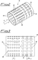
- Figure 2 shows a schematic example of said tubular body 16, whose surface is provided with a plurality of holes 28 and 30 having different diameters from one another, positioned respectively along two zones of the side surface of the tubular body 16, equal in length.
- the holes 30 having a larger diameter are also positioned at a larger distance from one another, at least in the longitudinal direction relative to the holes 28 having a smaller diameter; figure 3 schematically shows this embodiment, wherein the holes 28 are set at a distance from one another with a constant step "P", while the holes 30 are set at a distance from one another having a constant step "P 1 ". Holes 28 or 30 can however be positioned at any step whatsoever, also in the direction of the circumference around the tubular body 16.
- holes 28 and 30 are different from one another in both diameter and distance, they create at least two distinct zones with different passage areas for the mixture and therefore also with differing load loss.
- Figures 4 and 5 show schematic views of alternative embodiments of the tubular body 16, however, having the same object to provide thereon, at least two distinct zones with differing load loss.
- the tubular body 16 forming the distributor is provided with a plurality of holes 28 along the total side surface having the same diameter and the same distance between one another, but on the internal side surface of the same tubular body 16, an element is attached which acts to form a throttle in the mixture passage.
- Said throttle or deflector element is identified by numeral 32 in figure 4 and comprises a sleeve having a diameter which is narrower than that of tubular body 16, inside which it is inserted and fixed using conventional means such as metal distancers, welded, drawn or by means of interference fit.
- the deflector 32 presents a longitudinal extension which is shorter than the tubular body 16; for example, the deflector 32 presents a longitudinal extension equal to approximately half of the tubular body 16 forming the distributor, inside which it is fixed in such a manner that one of its ends is aligned with the end of the said tubular body 16.
- Figure 5 shows a variant embodiment of the deflector, which, in this case, is composed of an annular element identified by numeral 34.
- Said annular element having a limited height, for example between 0.5 and 20 mm, is fixed by welding or some equivalent means to the internal side surface of the tubular body 16, in a position that is practically central in relation to the overall longitudinal development.
Landscapes
- Engineering & Computer Science (AREA)
- Chemical & Material Sciences (AREA)
- Combustion & Propulsion (AREA)
- Mechanical Engineering (AREA)
- General Engineering & Computer Science (AREA)
- Gas Burners (AREA)
- Pre-Mixing And Non-Premixing Gas Burner (AREA)
Description
- The present invention relates to a differentiated distributor, especially suitable for premixed gas burners.
- More in particular, the present invention relates to a differentiated distributor having different load loss zones.
- It is known that, currently, in the construction of new boilers, there is a growing need to increase the performance in yield terms, and to reduce the size of the boiler at the same time. For this reason compact combustion apparatus have been designed and constructed with sealed combustion chambers. With particular reference to premixed gas burners however, considerable drawbacks have arisen with these new solutions, especially in relation to the presence of noise and resonance under different operating conditions, as well as difficulties with ignition in particular situations.
- These drawbacks are due to fluidodynamic effects that occur in the boiler system and which, for premixed gas burners, are related to the reduced size and the pressurised combustion chamber. In said chamber, operating conditions are also linked with the methods for evacuating fumes and for supplying the mixture.
- During the combustion process two types of slight oscillation occur causing noise. In fact there are mixture oscillations of both the total delivery and the air-gas ratio, due to the type of supply, which also influence the heat release; other fluctuations consist of pressure oscillation inside the combustion chamber, linked with the combustion itself, the type of combustion chamber and with the fume evacuation.
- When the heat release and pressure oscillations are in phase, there is an increase in noise levels.
- In an attempt to obviate these drawbacks a solution was provided which foresees the use of a converging or Venturi pipe, positioned inside the burner and upstream of the internal distributor.
- Such solution does solve, or at least substantially reduce the problems linked with noise levels and ignition difficulty to a large extent, since two zones having different mixture passage speeds on the burner head are created, and therefore the oscillations have different stages and intensity. When two flame zones are present with non-simultaneous oscillations, the noise is eliminated or, at least, considerably reduced. Ignition is also improved because the flame is stabilised on the combustion head along the low speed zone.
- However, the use of a converging pipe does provoke drawbacks that cannot be ignored.
- Firstly, the need to use said converging pipe means that this must be manufactured specifically, thus causing extra cost, which leads to a considerable increase in the total price of the burner; furthermore, the installation of the converging pipe involves more complex burner construction and maintenance.
- The documents
DE 202 12 202 U1 ,EP 1 584 868 A2 andUS 5 022 352 A show different mixture distributors of premixed gas burners. - Object of the present invention is to solve the drawbacks described above.
- More precisely, the object of the present invention is to provide a differentiated distributor, especially for premixed gas burners, and suitable for preventing noise and rumbling under different operating conditions.
- A further object of the invention is to provide a differentiated distributor to allow optimal and constant ignition of the mixture in all operating conditions.
- By no means the last object of the invention is to provide a differentiated distributor that does not require the use of additional components such as converging pipes to eliminate noise and to optimise mixture ignition.
- A further object of the invention is to provide users with a differentiated distributor, especially for premixed gas burners, suitable for guaranteeing high resistance and reliability levels for a long time and in a manner which is easy and economical to construct.
- These and other objects are achieved by a differentiated distributor according to the present invention as defined in claims 1 and 3 that is especially suitable for pre-mixed type gas burners equipped with a supply collector and with a combustion head housed in a container body forming the combustion chamber with flue, and which distributor comprises a tubular body provided with means forming different load loss zones along the said body.
- The constructive and functional features of the differentiated distributor of the present invention will be better understood from the following detailed description, wherein reference is made to the appended drawings, which illustrate non-limiting preferred embodiments wherein:
-
figure 1 shows a schematic enlarged view in perspective of a pre-mix burner equipped with a differentiated distributor according to the present invention; -
figure 2 shows a schematic view in perspective of the differentiated distributor according to the present invention; -
figure 3 shows a schematic side view of the same distributor; -
figure 4 shows a partial schematic view in perspective of the differentiated distributor according to the present invention in an alternative embodiment; -
figure 5 shows a partial schematic perspective view of the differentiated distributor according to the present invention according to a further possible embodiment. - With reference to the aforesaid figures, the differentiated distributor of the present invention is integrated with a gas burner, typically a premixed type gas burner, identified throughout by the numeral 10 shown in
figure 1 . - Said burner comprises a
collector 12 with the opening set at thebase 14 for the supply of the fuel mixture, a distributor formed by atubular body 16 and acombustion head 18 housed in acontainer body 20, provided with aflue 22, which defines the combustion chamber together with the relative heat exchanger (not illustrated). - The upper end opposite the
base 14 of thecollector 12 comprises anoutlet 24 for the mixture which is conveyed into thetubular body 16, partially inserted into thecombustion head 18 having a circular section, provided as an example. - According to the invention, the
tubular body 16, advantageously produced in metal such as stainless steel, and preferably having a circular section similar to thecombustion head 18, consists of atubular body 16 equipped with means suitable for creating different load loss zones - The arrow "F" in
figures 2 ,4 and 5 , indicates the inlet zone for the fuel into thetubular body 16. - In the embodiment provided as an example shown in
figures 2 and 3 , said means suitable for creating different load loss zones consist of a plurality of through-holes or openings having different diameters and distance spacing, positioned along the total surface of thetubular body 16 forming the distributor.Figure 2 shows a schematic example of saidtubular body 16, whose surface is provided with a plurality ofholes tubular body 16, equal in length. In addition, theholes 30 having a larger diameter, are also positioned at a larger distance from one another, at least in the longitudinal direction relative to theholes 28 having a smaller diameter;figure 3 schematically shows this embodiment, wherein theholes 28 are set at a distance from one another with a constant step "P", while theholes 30 are set at a distance from one another having a constant step "P1".Holes tubular body 16. - In any position whatsoever, since the
holes -
Figures 4 and 5 show schematic views of alternative embodiments of thetubular body 16, however, having the same object to provide thereon, at least two distinct zones with differing load loss. - In these embodiments, the
tubular body 16 forming the distributor is provided with a plurality ofholes 28 along the total side surface having the same diameter and the same distance between one another, but on the internal side surface of the sametubular body 16, an element is attached which acts to form a throttle in the mixture passage. - Said throttle or deflector element is identified by
numeral 32 infigure 4 and comprises a sleeve having a diameter which is narrower than that oftubular body 16, inside which it is inserted and fixed using conventional means such as metal distancers, welded, drawn or by means of interference fit. Thedeflector 32 presents a longitudinal extension which is shorter than thetubular body 16; for example, thedeflector 32 presents a longitudinal extension equal to approximately half of thetubular body 16 forming the distributor, inside which it is fixed in such a manner that one of its ends is aligned with the end of the saidtubular body 16.Figure 5 shows a variant embodiment of the deflector, which, in this case, is composed of an annular element identified bynumeral 34. Said annular element, having a limited height, for example between 0.5 and 20 mm, is fixed by welding or some equivalent means to the internal side surface of thetubular body 16, in a position that is practically central in relation to the overall longitudinal development. - Both in the case of the use of the
deflector 32 as well as the use of theannular element 34, at least two distinct zones having different load loss are created along thetubular body 16. Considering the aforesaid, the advantages gained by the invention are clear. - In the various alternatives described herein, with the different load loss zones created in the
tubular body 16 eliminate or at least reduce the noise and the rumbling to a large extent during burner operation, and at the same time, they prevent flame oscillation, guaranteeing optimal and constant ignition. - The aforesaid embodiments have resulted as being particularly efficient during the tests performed .
- Although the invention has been disclosed above with particular reference to certain embodiments, provided exclusively as a non-limiting example, numerous changes and variants will appear clear to those skilled in the art, considering the aforesaid description. Therefore, the present invention intends to include all the changes and variants within the scope of the following claims.
Claims (7)
- A differentiated distributor especially suitable for premixed gas burners (10), comprising a tubular body (16) having a side surface and equipped with means for forming two zones having different load losses along said tubular body (16), wherein said means are composed of a plurality of pass-through holes or openings (28, 30) positioned along the total side surface of said tubular body (16) and having different diameters and different distances from each other, the pass-through holes or openings (28) in one zone differing in diameter and distance from the pass-through holes or openings (30) in the other zone, thereby forming fuel mixture passage areas having different sizes, wherein the two zones are equal in length.
- Distributor according to the claim 1, wherein the tubular body (16) presents a circular section.
- A differentiated distributor especially suitable for premixed gas burners (10), comprising a tubular body (16) having a side surface and equipped with means for forming at least two zones having different load losses along said tubular body (16), wherein said means are composed of a passage throttle element forming a deflector (32, 34) fixed inside said tubular body (16), wherein the tubular body (16) comprises a plurality of pass-through holes or openings (28) having the same diameter and positioned along the total side surface of said tubular body (16) at the same distance from each other.
- Distributor according to claim 3, wherein the zones having different load losses are two and the means consist of a deflector (32) composed of a sleeve having a diameter that is narrower than that of the tubular body (16) and fixed along the internal side surface of said tubular body (16) by means of welded or drawn metal distancers or by means of interference fit, said deflector (32) presenting a longitudinal extension shorter than that of the tubular body (16).
- Distributor according to claim 3, wherein the zones having different load losses are two and the means consist of a deflector (34) composed of an annular element having a limited height and fixed to the internal side surface of the tubular body (16) through welding.
- Distributor according to claim 5, wherein the deflector (34) is fixed in the central zone of the distributor (16).
- Premixed gas burner (10) equipped with a supply collector (12), a container body (20) provided with a flue (22) and forming a combustion chamber, and a combustion head (18) housed in the container body (20), wherein the premixed gas burner (10) further comprises a distributor according to any of the preceding claims.
Applications Claiming Priority (1)
| Application Number | Priority Date | Filing Date | Title |
|---|---|---|---|
| IT001961A ITMI20061961A1 (en) | 2006-10-13 | 2006-10-13 | DIFFERENTIATED DISTRIBUTOR, SPECIES FOR PREMIXED BURNERS |
Publications (3)
| Publication Number | Publication Date |
|---|---|
| EP1914476A2 EP1914476A2 (en) | 2008-04-23 |
| EP1914476A3 EP1914476A3 (en) | 2014-01-22 |
| EP1914476B1 true EP1914476B1 (en) | 2019-01-30 |
Family
ID=38654756
Family Applications (1)
| Application Number | Title | Priority Date | Filing Date |
|---|---|---|---|
| EP07019532.6A Active EP1914476B1 (en) | 2006-10-13 | 2007-10-05 | Differentiated distributor, suitable for premixed gas burners |
Country Status (3)
| Country | Link |
|---|---|
| EP (1) | EP1914476B1 (en) |
| IT (1) | ITMI20061961A1 (en) |
| TR (1) | TR201905757T4 (en) |
Cited By (1)
| Publication number | Priority date | Publication date | Assignee | Title |
|---|---|---|---|---|
| IT202000002209A1 (en) | 2020-02-05 | 2021-08-05 | Polidoro S P A | PREMIX BURNER |
Families Citing this family (5)
| Publication number | Priority date | Publication date | Assignee | Title |
|---|---|---|---|---|
| ITMI20071751A1 (en) | 2007-09-12 | 2009-03-13 | Polidoro S P A | PREMIXED BURNER |
| EP2815179A1 (en) * | 2012-02-16 | 2014-12-24 | Bekaert Combustion Technology B.V. | Premix gas burner |
| ITUB20152184A1 (en) * | 2015-07-15 | 2017-01-15 | Worgas Bruciatori Srl | Burner with resonator |
| EP3431872A1 (en) * | 2017-07-17 | 2019-01-23 | Bekaert Combustion Technology B.V. | Cylindrical premix gas burner |
| CN109307268A (en) * | 2017-07-29 | 2019-02-05 | 上海钜荷热力技术有限公司 | A kind of flue gas is interior to recycle all-premixing burner |
Family Cites Families (3)
| Publication number | Priority date | Publication date | Assignee | Title |
|---|---|---|---|---|
| US5022352A (en) * | 1990-05-31 | 1991-06-11 | Mor-Flo Industries, Inc. | Burner for forced draft controlled mixture heating system using a closed combustion chamber |
| DE20212202U1 (en) * | 2002-08-08 | 2002-11-07 | Buderus Heiztechnik Gmbh, 35576 Wetzlar | Premixing gas burner |
| JP3958754B2 (en) * | 2004-04-09 | 2007-08-15 | リンナイ株式会社 | Cylindrical burner |
-
2006
- 2006-10-13 IT IT001961A patent/ITMI20061961A1/en unknown
-
2007
- 2007-10-05 EP EP07019532.6A patent/EP1914476B1/en active Active
- 2007-10-05 TR TR2019/05757T patent/TR201905757T4/en unknown
Non-Patent Citations (1)
| Title |
|---|
| None * |
Cited By (2)
| Publication number | Priority date | Publication date | Assignee | Title |
|---|---|---|---|---|
| IT202000002209A1 (en) | 2020-02-05 | 2021-08-05 | Polidoro S P A | PREMIX BURNER |
| EP4450870A1 (en) | 2020-02-05 | 2024-10-23 | Polidoro S.p.A. | Premix burner |
Also Published As
| Publication number | Publication date |
|---|---|
| ITMI20061961A1 (en) | 2008-04-14 |
| EP1914476A2 (en) | 2008-04-23 |
| TR201905757T4 (en) | 2019-05-21 |
| EP1914476A3 (en) | 2014-01-22 |
Similar Documents
| Publication | Publication Date | Title |
|---|---|---|
| EP1914476B1 (en) | Differentiated distributor, suitable for premixed gas burners | |
| EP2954260B1 (en) | Fuel nozzle for a gas turbine combustor | |
| US8814560B2 (en) | Device and method for stabilizing the pressure and the flow of a gaseous mixture supplied to a surface-combustion cylindrical burner | |
| US20030143502A1 (en) | Large scale vortex devices for improved burner operation | |
| JP3938358B2 (en) | Flare stack combustion apparatus and method | |
| US6036481A (en) | Burner with flame retainer insert | |
| EP2220435A1 (en) | Fuel injection system and burner using the same | |
| CN103062799A (en) | Flashback resistant tubes in tube lli design | |
| CN109114592A (en) | The method of combustion system and the combustion product for generating tool premixed flame characteristic | |
| JP2005265403A (en) | Turbine combustor transition part with dilution holes | |
| WO1993012379A1 (en) | Jet burner construction, heating apparatus utilizing the jet burner consturction and methods of making the same | |
| CA3055300A1 (en) | Adjustable restrictor for burner | |
| US10006628B2 (en) | Low NOx gas burners with carryover ignition | |
| RU2605166C2 (en) | Universal mixing head swirl atomizer for gas burner | |
| US6485294B2 (en) | NOx reduction device | |
| US7052273B2 (en) | Premixed fuel burner assembly | |
| EP0754917A3 (en) | Combustion device in lighters | |
| EP2588808B1 (en) | Gas burner with means for preventing flame propagation | |
| WO2015051226A1 (en) | Low nox burner with low pressure drop | |
| KR100864846B1 (en) | Premix Combustion Burner | |
| US20060088794A1 (en) | Superheating burner with turbulence ring | |
| US6551098B2 (en) | Variable firing rate fuel burner | |
| KR20200007008A (en) | Vortex Recirculation Combustion Burner Head | |
| JP2001056107A (en) | Gas burner | |
| JP2008520950A (en) | Heater burner with improved fuel supply, improved heat shield and improved baffle plate |
Legal Events
| Date | Code | Title | Description |
|---|---|---|---|
| PUAI | Public reference made under article 153(3) epc to a published international application that has entered the european phase |
Free format text: ORIGINAL CODE: 0009012 |
|
| AK | Designated contracting states |
Kind code of ref document: A2 Designated state(s): AT BE BG CH CY CZ DE DK EE ES FI FR GB GR HU IE IS IT LI LT LU LV MC MT NL PL PT RO SE SI SK TR |
|
| AX | Request for extension of the european patent |
Extension state: AL BA HR MK RS |
|
| PUAL | Search report despatched |
Free format text: ORIGINAL CODE: 0009013 |
|
| AK | Designated contracting states |
Kind code of ref document: A3 Designated state(s): AT BE BG CH CY CZ DE DK EE ES FI FR GB GR HU IE IS IT LI LT LU LV MC MT NL PL PT RO SE SI SK TR |
|
| AX | Request for extension of the european patent |
Extension state: AL BA HR MK RS |
|
| RIC1 | Information provided on ipc code assigned before grant |
Ipc: F23D 14/58 20060101ALI20131217BHEP Ipc: F23D 14/62 20060101ALI20131217BHEP Ipc: F23D 14/10 20060101ALI20131217BHEP Ipc: F23D 14/06 20060101AFI20131217BHEP Ipc: F23D 14/70 20060101ALI20131217BHEP |
|
| 17P | Request for examination filed |
Effective date: 20140610 |
|
| AKX | Designation fees paid |
Designated state(s): AT BE BG CH CY CZ DE DK EE ES FI FR GB GR HU IE IS IT LI LT LU LV MC MT NL PL PT RO SE SI SK TR |
|
| 17Q | First examination report despatched |
Effective date: 20160104 |
|
| STAA | Information on the status of an ep patent application or granted ep patent |
Free format text: STATUS: EXAMINATION IS IN PROGRESS |
|
| GRAP | Despatch of communication of intention to grant a patent |
Free format text: ORIGINAL CODE: EPIDOSNIGR1 |
|
| STAA | Information on the status of an ep patent application or granted ep patent |
Free format text: STATUS: GRANT OF PATENT IS INTENDED |
|
| INTG | Intention to grant announced |
Effective date: 20180925 |
|
| GRAS | Grant fee paid |
Free format text: ORIGINAL CODE: EPIDOSNIGR3 |
|
| GRAA | (expected) grant |
Free format text: ORIGINAL CODE: 0009210 |
|
| STAA | Information on the status of an ep patent application or granted ep patent |
Free format text: STATUS: THE PATENT HAS BEEN GRANTED |
|
| AK | Designated contracting states |
Kind code of ref document: B1 Designated state(s): AT BE BG CH CY CZ DE DK EE ES FI FR GB GR HU IE IS IT LI LT LU LV MC MT NL PL PT RO SE SI SK TR |
|
| REG | Reference to a national code |
Ref country code: GB Ref legal event code: FG4D |
|
| REG | Reference to a national code |
Ref country code: CH Ref legal event code: EP |
|
| REG | Reference to a national code |
Ref country code: AT Ref legal event code: REF Ref document number: 1093576 Country of ref document: AT Kind code of ref document: T Effective date: 20190215 |
|
| REG | Reference to a national code |
Ref country code: IE Ref legal event code: FG4D |
|
| REG | Reference to a national code |
Ref country code: DE Ref legal event code: R096 Ref document number: 602007057533 Country of ref document: DE |
|
| REG | Reference to a national code |
Ref country code: LT Ref legal event code: MG4D |
|
| REG | Reference to a national code |
Ref country code: NL Ref legal event code: MP Effective date: 20190130 |
|
| PG25 | Lapsed in a contracting state [announced via postgrant information from national office to epo] |
Ref country code: ES Free format text: LAPSE BECAUSE OF FAILURE TO SUBMIT A TRANSLATION OF THE DESCRIPTION OR TO PAY THE FEE WITHIN THE PRESCRIBED TIME-LIMIT Effective date: 20190130 Ref country code: PL Free format text: LAPSE BECAUSE OF FAILURE TO SUBMIT A TRANSLATION OF THE DESCRIPTION OR TO PAY THE FEE WITHIN THE PRESCRIBED TIME-LIMIT Effective date: 20190130 Ref country code: LT Free format text: LAPSE BECAUSE OF FAILURE TO SUBMIT A TRANSLATION OF THE DESCRIPTION OR TO PAY THE FEE WITHIN THE PRESCRIBED TIME-LIMIT Effective date: 20190130 Ref country code: PT Free format text: LAPSE BECAUSE OF FAILURE TO SUBMIT A TRANSLATION OF THE DESCRIPTION OR TO PAY THE FEE WITHIN THE PRESCRIBED TIME-LIMIT Effective date: 20190530 Ref country code: FI Free format text: LAPSE BECAUSE OF FAILURE TO SUBMIT A TRANSLATION OF THE DESCRIPTION OR TO PAY THE FEE WITHIN THE PRESCRIBED TIME-LIMIT Effective date: 20190130 Ref country code: SE Free format text: LAPSE BECAUSE OF FAILURE TO SUBMIT A TRANSLATION OF THE DESCRIPTION OR TO PAY THE FEE WITHIN THE PRESCRIBED TIME-LIMIT Effective date: 20190130 |
|
| REG | Reference to a national code |
Ref country code: AT Ref legal event code: MK05 Ref document number: 1093576 Country of ref document: AT Kind code of ref document: T Effective date: 20190130 |
|
| PG25 | Lapsed in a contracting state [announced via postgrant information from national office to epo] |
Ref country code: BG Free format text: LAPSE BECAUSE OF FAILURE TO SUBMIT A TRANSLATION OF THE DESCRIPTION OR TO PAY THE FEE WITHIN THE PRESCRIBED TIME-LIMIT Effective date: 20190430 Ref country code: GR Free format text: LAPSE BECAUSE OF FAILURE TO SUBMIT A TRANSLATION OF THE DESCRIPTION OR TO PAY THE FEE WITHIN THE PRESCRIBED TIME-LIMIT Effective date: 20190501 Ref country code: IS Free format text: LAPSE BECAUSE OF FAILURE TO SUBMIT A TRANSLATION OF THE DESCRIPTION OR TO PAY THE FEE WITHIN THE PRESCRIBED TIME-LIMIT Effective date: 20190530 Ref country code: LV Free format text: LAPSE BECAUSE OF FAILURE TO SUBMIT A TRANSLATION OF THE DESCRIPTION OR TO PAY THE FEE WITHIN THE PRESCRIBED TIME-LIMIT Effective date: 20190130 Ref country code: NL Free format text: LAPSE BECAUSE OF FAILURE TO SUBMIT A TRANSLATION OF THE DESCRIPTION OR TO PAY THE FEE WITHIN THE PRESCRIBED TIME-LIMIT Effective date: 20190130 |
|
| PG25 | Lapsed in a contracting state [announced via postgrant information from national office to epo] |
Ref country code: EE Free format text: LAPSE BECAUSE OF FAILURE TO SUBMIT A TRANSLATION OF THE DESCRIPTION OR TO PAY THE FEE WITHIN THE PRESCRIBED TIME-LIMIT Effective date: 20190130 Ref country code: SK Free format text: LAPSE BECAUSE OF FAILURE TO SUBMIT A TRANSLATION OF THE DESCRIPTION OR TO PAY THE FEE WITHIN THE PRESCRIBED TIME-LIMIT Effective date: 20190130 Ref country code: RO Free format text: LAPSE BECAUSE OF FAILURE TO SUBMIT A TRANSLATION OF THE DESCRIPTION OR TO PAY THE FEE WITHIN THE PRESCRIBED TIME-LIMIT Effective date: 20190130 Ref country code: CZ Free format text: LAPSE BECAUSE OF FAILURE TO SUBMIT A TRANSLATION OF THE DESCRIPTION OR TO PAY THE FEE WITHIN THE PRESCRIBED TIME-LIMIT Effective date: 20190130 Ref country code: DK Free format text: LAPSE BECAUSE OF FAILURE TO SUBMIT A TRANSLATION OF THE DESCRIPTION OR TO PAY THE FEE WITHIN THE PRESCRIBED TIME-LIMIT Effective date: 20190130 |
|
| REG | Reference to a national code |
Ref country code: DE Ref legal event code: R097 Ref document number: 602007057533 Country of ref document: DE |
|
| PLBE | No opposition filed within time limit |
Free format text: ORIGINAL CODE: 0009261 |
|
| STAA | Information on the status of an ep patent application or granted ep patent |
Free format text: STATUS: NO OPPOSITION FILED WITHIN TIME LIMIT |
|
| PG25 | Lapsed in a contracting state [announced via postgrant information from national office to epo] |
Ref country code: AT Free format text: LAPSE BECAUSE OF FAILURE TO SUBMIT A TRANSLATION OF THE DESCRIPTION OR TO PAY THE FEE WITHIN THE PRESCRIBED TIME-LIMIT Effective date: 20190130 |
|
| 26N | No opposition filed |
Effective date: 20191031 |
|
| PG25 | Lapsed in a contracting state [announced via postgrant information from national office to epo] |
Ref country code: SI Free format text: LAPSE BECAUSE OF FAILURE TO SUBMIT A TRANSLATION OF THE DESCRIPTION OR TO PAY THE FEE WITHIN THE PRESCRIBED TIME-LIMIT Effective date: 20190130 |
|
| PG25 | Lapsed in a contracting state [announced via postgrant information from national office to epo] |
Ref country code: MC Free format text: LAPSE BECAUSE OF FAILURE TO SUBMIT A TRANSLATION OF THE DESCRIPTION OR TO PAY THE FEE WITHIN THE PRESCRIBED TIME-LIMIT Effective date: 20190130 |
|
| REG | Reference to a national code |
Ref country code: CH Ref legal event code: PL |
|
| PG25 | Lapsed in a contracting state [announced via postgrant information from national office to epo] |
Ref country code: LU Free format text: LAPSE BECAUSE OF NON-PAYMENT OF DUE FEES Effective date: 20191005 Ref country code: LI Free format text: LAPSE BECAUSE OF NON-PAYMENT OF DUE FEES Effective date: 20191031 Ref country code: CH Free format text: LAPSE BECAUSE OF NON-PAYMENT OF DUE FEES Effective date: 20191031 |
|
| REG | Reference to a national code |
Ref country code: BE Ref legal event code: MM Effective date: 20191031 |
|
| PG25 | Lapsed in a contracting state [announced via postgrant information from national office to epo] |
Ref country code: BE Free format text: LAPSE BECAUSE OF NON-PAYMENT OF DUE FEES Effective date: 20191031 |
|
| PG25 | Lapsed in a contracting state [announced via postgrant information from national office to epo] |
Ref country code: IE Free format text: LAPSE BECAUSE OF NON-PAYMENT OF DUE FEES Effective date: 20191005 Ref country code: FR Free format text: LAPSE BECAUSE OF NON-PAYMENT OF DUE FEES Effective date: 20191031 |
|
| PG25 | Lapsed in a contracting state [announced via postgrant information from national office to epo] |
Ref country code: CY Free format text: LAPSE BECAUSE OF FAILURE TO SUBMIT A TRANSLATION OF THE DESCRIPTION OR TO PAY THE FEE WITHIN THE PRESCRIBED TIME-LIMIT Effective date: 20190130 |
|
| PG25 | Lapsed in a contracting state [announced via postgrant information from national office to epo] |
Ref country code: HU Free format text: LAPSE BECAUSE OF FAILURE TO SUBMIT A TRANSLATION OF THE DESCRIPTION OR TO PAY THE FEE WITHIN THE PRESCRIBED TIME-LIMIT; INVALID AB INITIO Effective date: 20071005 Ref country code: MT Free format text: LAPSE BECAUSE OF FAILURE TO SUBMIT A TRANSLATION OF THE DESCRIPTION OR TO PAY THE FEE WITHIN THE PRESCRIBED TIME-LIMIT Effective date: 20190130 |
|
| PGFP | Annual fee paid to national office [announced via postgrant information from national office to epo] |
Ref country code: TR Payment date: 20221004 Year of fee payment: 16 Ref country code: IT Payment date: 20221005 Year of fee payment: 16 Ref country code: GB Payment date: 20221018 Year of fee payment: 16 Ref country code: DE Payment date: 20221028 Year of fee payment: 16 |
|
| P01 | Opt-out of the competence of the unified patent court (upc) registered |
Effective date: 20230522 |
|
| REG | Reference to a national code |
Ref country code: DE Ref legal event code: R119 Ref document number: 602007057533 Country of ref document: DE |
|
| GBPC | Gb: european patent ceased through non-payment of renewal fee |
Effective date: 20231005 |
|
| PG25 | Lapsed in a contracting state [announced via postgrant information from national office to epo] |
Ref country code: GB Free format text: LAPSE BECAUSE OF NON-PAYMENT OF DUE FEES Effective date: 20231005 |
|
| PG25 | Lapsed in a contracting state [announced via postgrant information from national office to epo] |
Ref country code: GB Free format text: LAPSE BECAUSE OF NON-PAYMENT OF DUE FEES Effective date: 20231005 Ref country code: DE Free format text: LAPSE BECAUSE OF NON-PAYMENT OF DUE FEES Effective date: 20240501 |
|
| PG25 | Lapsed in a contracting state [announced via postgrant information from national office to epo] |
Ref country code: IT Free format text: LAPSE BECAUSE OF NON-PAYMENT OF DUE FEES Effective date: 20231005 |
|
| PG25 | Lapsed in a contracting state [announced via postgrant information from national office to epo] |
Ref country code: IT Free format text: LAPSE BECAUSE OF NON-PAYMENT OF DUE FEES Effective date: 20231005 |