EP1914440A1 - Method of manufacturing resin coiled spring and resin coiled spring - Google Patents
Method of manufacturing resin coiled spring and resin coiled spring Download PDFInfo
- Publication number
- EP1914440A1 EP1914440A1 EP06782193A EP06782193A EP1914440A1 EP 1914440 A1 EP1914440 A1 EP 1914440A1 EP 06782193 A EP06782193 A EP 06782193A EP 06782193 A EP06782193 A EP 06782193A EP 1914440 A1 EP1914440 A1 EP 1914440A1
- Authority
- EP
- European Patent Office
- Prior art keywords
- spring
- coil
- resin
- unit
- plural
- Prior art date
- Legal status (The legal status is an assumption and is not a legal conclusion. Google has not performed a legal analysis and makes no representation as to the accuracy of the status listed.)
- Withdrawn
Links
Images




Classifications
-
- F—MECHANICAL ENGINEERING; LIGHTING; HEATING; WEAPONS; BLASTING
- F16—ENGINEERING ELEMENTS AND UNITS; GENERAL MEASURES FOR PRODUCING AND MAINTAINING EFFECTIVE FUNCTIONING OF MACHINES OR INSTALLATIONS; THERMAL INSULATION IN GENERAL
- F16F—SPRINGS; SHOCK-ABSORBERS; MEANS FOR DAMPING VIBRATION
- F16F1/00—Springs
- F16F1/36—Springs made of rubber or other material having high internal friction, e.g. thermoplastic elastomers
- F16F1/366—Springs made of rubber or other material having high internal friction, e.g. thermoplastic elastomers made of fibre-reinforced plastics, i.e. characterised by their special construction from such materials
- F16F1/3665—Wound springs
-
- B—PERFORMING OPERATIONS; TRANSPORTING
- B05—SPRAYING OR ATOMISING IN GENERAL; APPLYING FLUENT MATERIALS TO SURFACES, IN GENERAL
- B05B—SPRAYING APPARATUS; ATOMISING APPARATUS; NOZZLES
- B05B11/00—Single-unit hand-held apparatus in which flow of contents is produced by the muscular force of the operator at the moment of use
- B05B11/01—Single-unit hand-held apparatus in which flow of contents is produced by the muscular force of the operator at the moment of use characterised by the means producing the flow
- B05B11/10—Pump arrangements for transferring the contents from the container to a pump chamber by a sucking effect and forcing the contents out through the dispensing nozzle
- B05B11/1042—Components or details
- B05B11/1073—Springs
- B05B11/1077—Springs characterised by a particular shape or material
-
- F—MECHANICAL ENGINEERING; LIGHTING; HEATING; WEAPONS; BLASTING
- F16—ENGINEERING ELEMENTS AND UNITS; GENERAL MEASURES FOR PRODUCING AND MAINTAINING EFFECTIVE FUNCTIONING OF MACHINES OR INSTALLATIONS; THERMAL INSULATION IN GENERAL
- F16F—SPRINGS; SHOCK-ABSORBERS; MEANS FOR DAMPING VIBRATION
- F16F1/00—Springs
- F16F1/02—Springs made of steel or other material having low internal friction; Wound, torsion, leaf, cup, ring or the like springs, the material of the spring not being relevant
- F16F1/025—Springs made of steel or other material having low internal friction; Wound, torsion, leaf, cup, ring or the like springs, the material of the spring not being relevant characterised by having a particular shape
-
- F—MECHANICAL ENGINEERING; LIGHTING; HEATING; WEAPONS; BLASTING
- F16—ENGINEERING ELEMENTS AND UNITS; GENERAL MEASURES FOR PRODUCING AND MAINTAINING EFFECTIVE FUNCTIONING OF MACHINES OR INSTALLATIONS; THERMAL INSULATION IN GENERAL
- F16F—SPRINGS; SHOCK-ABSORBERS; MEANS FOR DAMPING VIBRATION
- F16F1/00—Springs
- F16F1/36—Springs made of rubber or other material having high internal friction, e.g. thermoplastic elastomers
- F16F1/42—Springs made of rubber or other material having high internal friction, e.g. thermoplastic elastomers characterised by the mode of stressing
- F16F1/422—Springs made of rubber or other material having high internal friction, e.g. thermoplastic elastomers characterised by the mode of stressing the stressing resulting in flexion of the spring
Definitions
- the present invention relates to a resin coil spring and a method of manufacturing the resin coil spring.
- a reagent container employed in an automated analyzer includes a metallic compression spring in a cap.
- a used reagent container must be disposed as medical waste.
- the reagent container cannot be disposed as it is unless the metallic compression spring is removed.
- One way to solve this problem is to use a resin spring which is used in a liquid-filling pump with a push-down head and the like instead of the metallic compression spring (see, for example Patent Document 1).
- Patent Document 1 Japanese Patent Application Laid-Open No. H10-73138
- a coil spring made of synthetic resin described in Patent Document 1 is an integrally-molded piece. Therefore, a metal mold must be prepared for each spring of a particular size, such as diameter and length, which makes the coil spring expensive.
- the present invention is made in view of the above, and an object of the present invention is to provide a resin coil spring and a method of manufacturing the resin coil spring which can be adapted to manufacture of springs of different lengths and the same diameter, and which can provide resin coil springs of different lengths at low cost.
- one embodiment of a method of manufacturing a resin coil spring according to the present invention includes integrally molding a spring unit from synthetic resin, the spring unit including a coil unit having plural coil members, and ring-like supports respectively arranged on two sides of the coil unit and connected to an end of each of the plural coil members, and stacking the molded spring units one on another.
- one embodiment of a resin coil spring according to the present invention includes plural spring units each integrally molded from synthetic resin and stacked one on another, and the spring unit includes a coil unit having plural coil members, and ring-like supports respectively arranged on two sides of the coil unit and connected to an end of each of the plural coil members.
- a direction of winding of each coil member is same in each spring unit of the plural spring units.
- a direction of winding of the coil members of each of the spring units is different from a direction of winding of the coil members of an adjacent one of the spring units.
- a pitch angle of each of the plural coil members is set equal to or narrower than 20° in one of the spring units having one direction of winding and outnumbering the spring units having a different direction of winding.
- ends of the plural coil members are connected to the supports at equal intervals along a circumferential direction.
- the method of manufacturing the resin coil spring according to the present invention includes integrally molding a spring unit from synthetic resin, and stacking the molded spring units one on another, and the resin coil spring according to the present invention is manufactured from plural spring units stacked one on another, resin coil springs of different lengths and the same diameter can be easily manufactured, and resin coil springs of different lengths can be provided at low cost.
- FIG. 1 is a perspective view of a resin coil spring according to the first embodiment which is manufactured by the method of manufacturing a resin coil spring according to the present invention.
- FIG. 2 is a perspective view of a left-handed spring unit which constitutes the resin coil spring of FIG. 1 .
- FIG. 3 is a front view of the spring unit shown in FIG. 2 .
- a resin coil spring 1 includes, as shown in FIG. 1 , two left-handed spring units 2 molded from synthetic resin such as polyacetal.
- the spring unit 2 includes a coil unit 2a, and ring-like supports 2b which are arranged on two sides of the coil unit 2a, and the spring unit 2 is integrally molded from synthetic resin.
- the coil unit 2a has two coil members 2c, and two ends of each coil member 2c are connected to the supports 2b arranged on two sides, respectively.
- two coil members 2c are supported by the supports 2b.
- the upper support 2b has plural holes 2d on the upper surface
- the lower support 2b has plural bosses 2e on the lower surface so as to engage with the holes 2d.
- the number of turns of the coil member 2c is 1/2 turn, and two coil members 2c are connected to the supports 2b on two sides at equal intervals, with the ends of one coil member being shifted from the ends of the other coil member respectively by 180° in a circumferential direction.
- the spring force of the spring unit 2 can be increased.
- the coil member 2c of the spring unit 2 tends to bulge in a radially outward direction about the central axis when being compressed.
- an outer circumferential portion of the coil member 2c is brought into contact with a wall or the like of an object for which the spring unit 2 is employed depending on the type of the object.
- the spring unit 2 cannot work as a spring.
- the spring unit 2 cannot exert sufficient spring force because of the friction between the outer circumferential portion of the coil member 2c and the wall or the like.
- the spring unit 2 cannot have a required spring force.
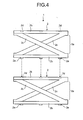
- the resin coil spring 1 configured as described above is manufactured from two spring units 2 each molded integrally and stacked one on another so that the holes 2d engage with the corresponding bosses 2e respectively as shown in FIG. 4 .
- the mutually-opposed supports 2b respectively of two spring units 2 may be bonded with each other with an adhesive.
- the resin coil spring 1 of the present invention can be easily made into a resin coil spring of a different length when being combined with other spring units of the same diameter stacked one on another, whereby resin coil springs of different lengths can be provided at a low cost.
- the resin coil spring 1 of the first embodiment is manufactured from two left-handed spring units 2 stacked one on another.
- the resin coil spring of the second embodiment is manufactured from one left-handed spring unit 2 and one right-handed spring unit placed one on another.
- FIG. 5 is a perspective view of a resin coil spring 5 according to the second embodiment.
- FIG. 6 is a perspective view of a right-handed spring unit which constitutes the resin coil spring of FIG. 5 .
- FIG. 7 is a front view of the spring unit shown in FIG. 6 .
- parts corresponding to the parts of the resin coil spring 1 of the first embodiment are designated by the same reference characters.
- the resin coil spring 5 includes a left-handed spring unit 2 and a right-handed spring unit 4 each integrally molded from synthetic resin such as polyacetal as shown in FIG. 5 .
- the spring unit 4 is the same with the spring unit 2 in structure except that the direction of winding is different.
- the spring unit 4 includes a coil unit 4a having two coil members 4c, and ring-like supports 4b arranged on two sides of the coil unit 4a.
- the upper support 4b has plural holes 4d on the upper surface, whereas the lower support 4b has plural bosses 4e on the lower surface.
- the holes 4d and the bosses 4e are formed in such positions that the coil member 2c shifts from the coil member 4c at the supports 2b and 4b by 90° in a circumferential direction when the boss 2e and the hole 4d, or the hole 2d and the boss 4e are engaged with each other.
- the resin coil spring 5 configured as described above is easily manufactured from the spring unit 2 and the spring unit 4 each integrally molded and placed one on another so that the bosses 2e engage with the corresponding holes 4d, as shown in FIG. 8 .
- the mutually-opposed supports 2b and 4b respectively of the spring unit 2 and the spring unit 4 may be bonded with each other with an adhesive. Further, in the resin coil spring 5, it is possible to arrange the spring unit 4 on the spring unit 2 and to make the bosses 4e engage with the corresponding holes 2d.
- the support 2b or the support 4b may rotate in the circumferential direction in accordance with the direction of winding of the coil members 2c or 4c.
- the spring unit 2 and the spring unit 4 having different directions of winding are placed one on another and combined as in the resin coil spring 5, even if the support 2b or the support 4b rotates in the circumferential direction at the time of expansion or contraction, the rotations are in opposite directions. Therefore, the rotations of the supports 2b and 4b offset with each other.
- the resin coil spring 5 can prevent the friction resistance caused by the rotation of the supports 2b and 4b from negatively affecting the expansion and contraction of the coil members 2c and 4c, whereby the resin coil spring 5 can sufficiently work as a spring. Therefore, when the spring units with different directions of winding are combined in the resin coil spring of the present invention, preferably an even number of spring units are combined.
- the resin coil springs 1 and 5 of the first and the second embodiments are short resin coil springs made from two spring units stacked one on another.
- the resin coil spring of the third embodiment is a long resin coil spring wherein five spring units including the left-handed spring units 2 and the right-handed spring units 4 are stacked.
- FIG. 9 is a front view of a resin coil spring 10 according to the third embodiment.
- the resin coil spring 10 includes two left-handed spring units 2 and three right-handed spring units 4 as shown in FIG. 9 .
- the spring units 2 and the spring units 4 each integrally molded are arranged so that the adjacent spring units have different directions of winding, and stacked one on another so that the bosses 2e and corresponding holes 4d or the holes 2d and the corresponding bosses 4e are engaged with each other.
- the mutually-opposed supports 2b and 4b of the adjacent spring units 2 and 4 may be bonded with each other with an adhesive.
- the pitch angle of the coil member 4c of one spring unit 4 is set equal to or narrower than 20°, so as to prevent the rotation of the supports 4b of the spring unit 4.
- the resin coil spring 10 can prevent the rotation of the support 4b attributable to the spring units 4 whose number is larger than the other spring units by one.
- the pitch angle of the coil members 2c and 4c of all the spring units 2 and 4 stacked one on another may be set equal to or narrower than 20°.
- the method of manufacturing the resin coil spring according to the present invention includes integrally molding a spring unit from synthetic resin, and stacking a plurality of the molded spring units one on another.
- the resin coil spring of the present invention is manufactured from plural spring units stacked one on another. Therefore, the resin coil springs of the present invention can be manufactured from any number of spring units stacked one on another depending on the required length, as far as the diameters of the spring units are the same. Preparing two types of spring units, namely, the left-handed spring units and the right-handed spring units in advance should be sufficient.
- the resin coil spring of the present invention may be integrally molded from synthetic resin, and configured as a resin coil spring 15 shown in FIGS. 10 and 11 , so that two coil units 15a are connected with each other via three ring-like supports 15b, and two coil members 15c respectively in adjacent coil units 15a may have opposite directions of winding, in other words, one coil member 15c may be right-handed and the other coil member 15c may be left-handed.
- the number of turns of the coil member 15c is 1/2 turn, and two coil members 15c are connected to the supports 15b on two sides so that two ends of one coil member is shifted from two ends of another coil member by 180° in the circumferential direction. Further, the end of the coil member 15c of one coil unit 15a is placed 90° off from the end of the coil member 15c of the adjacent coil unit 15a on the support 15b in the circumferential direction.
- the method of manufacturing a resin coil spring and a resin coil spring according to the present invention can be adapted to resin coil springs of various lengths and the same diameter, and therefore, are useful for providing resin coil springs of different lengths at low cost, and in particular, are suitable for a resin coil spring used in a cap of a reagent container employed in an automated analyzer.
Landscapes
- Engineering & Computer Science (AREA)
- General Engineering & Computer Science (AREA)
- Mechanical Engineering (AREA)
- Health & Medical Sciences (AREA)
- Child & Adolescent Psychology (AREA)
- Springs (AREA)
Abstract
A method of manufacturing a resin coil spring including integrally molding a spring unit (2) from synthetic resin, the spring unit (2) including a coil unit (2a) having plural coil members (2c) and ring-like supports (2b) respectively arranged on two sides of the coil unit and connected to an end of each of the plural coil members, and stacking the molded plural spring units (2) one on another, and a resin coil spring (1) including plural spring units (2) each integrally molded from synthetic resin and stacked one on another, the spring unit including a coil unit (2a) having plural coil members (2c) and ring-like supports (2b) respectively arranged on two sides of the coil unit and connected to an end of each of the plural coil members.
Description
- The present invention relates to a resin coil spring and a method of manufacturing the resin coil spring.
- Conventionally, a reagent container employed in an automated analyzer includes a metallic compression spring in a cap. A used reagent container must be disposed as medical waste. However, when a main body of the reagent container is made of synthetic resin, the reagent container cannot be disposed as it is unless the metallic compression spring is removed. One way to solve this problem is to use a resin spring which is used in a liquid-filling pump with a push-down head and the like instead of the metallic compression spring (see, for example Patent Document 1).
- Patent Document 1:
Japanese Patent Application Laid-Open No. H10-73138 - However, a coil spring made of synthetic resin described in
Patent Document 1 is an integrally-molded piece. Therefore, a metal mold must be prepared for each spring of a particular size, such as diameter and length, which makes the coil spring expensive. - The present invention is made in view of the above, and an object of the present invention is to provide a resin coil spring and a method of manufacturing the resin coil spring which can be adapted to manufacture of springs of different lengths and the same diameter, and which can provide resin coil springs of different lengths at low cost.
- To solve the problem as described above and to achieve an object, one embodiment of a method of manufacturing a resin coil spring according to the present invention includes integrally molding a spring unit from synthetic resin, the spring unit including a coil unit having plural coil members, and ring-like supports respectively arranged on two sides of the coil unit and connected to an end of each of the plural coil members, and stacking the molded spring units one on another.
- Further, to solve the problem as described above and to achieve an object, one embodiment of a resin coil spring according to the present invention includes plural spring units each integrally molded from synthetic resin and stacked one on another, and the spring unit includes a coil unit having plural coil members, and ring-like supports respectively arranged on two sides of the coil unit and connected to an end of each of the plural coil members.
- Further, in one embodiment of the resin coil spring according to the present invention as described above, a direction of winding of each coil member is same in each spring unit of the plural spring units.
- Further, in one embodiment of the resin coil spring according to the present invention as described above, a direction of winding of the coil members of each of the spring units is different from a direction of winding of the coil members of an adjacent one of the spring units.
- Further, in one embodiment of the resin coil spring according to the present invention as described above, when the plural spring units are odd in number, a pitch angle of each of the plural coil members is set equal to or narrower than 20° in one of the spring units having one direction of winding and outnumbering the spring units having a different direction of winding.
- Further, in one embodiment of the resin coil spring according to the present invention as described above, in each of the spring units, ends of the plural coil members are connected to the supports at equal intervals along a circumferential direction.
- Since the method of manufacturing the resin coil spring according to the present invention includes integrally molding a spring unit from synthetic resin, and stacking the molded spring units one on another, and the resin coil spring according to the present invention is manufactured from plural spring units stacked one on another, resin coil springs of different lengths and the same diameter can be easily manufactured, and resin coil springs of different lengths can be provided at low cost.
-
-
FIG. 1 is a perspective view of a resin coil spring according to a first embodiment manufactured by a method of manufacturing a resin coil spring according to the present invention; -
FIG. 2 is a perspective view of a left-handed spring unit which constitutes the resin coil spring ofFIG. 1 ; -
FIG. 3 is a front view of the spring unit shown inFIG. 2 ; -
FIG. 4 is a view for explaining a method of manufacturing the resin coil spring shown inFIG. 1 by stacking the spring units shown inFIG. 2 one on another; -
FIG. 5 is a perspective view of a resin coil spring according to a second embodiment; -
FIG. 6 is a perspective view of a right-handed spring unit which constitutes the resin coil spring ofFIG. 5 ; -
FIG. 7 is a front view of the spring unit shown inFIG. 6 ; -
FIG. 8 is a view for explaining a method of manufacturing the resin coil spring shown inFIG. 5 by stacking the spring unit shown inFIG. 2 on the spring unit shown inFIG. 6 ; -
FIG. 9 is a front view of a resin coil spring according to a third embodiment; -
FIG. 10 is a perspective view of a modification of the resin coil spring; and -
FIG. 11 is a front view of the resin coil spring shown inFIG. 10 . -
- 1
- resin coil spring
- 2
- spring unit
- 2a
- coil unit
- 2b
- support
- 2c
- coil member
- 2d
- hole
- 2e
- boss
- 4
- spring unit
- 4a
- coil unit
- 4b
- support
- 4c
- coil member
- 4d
- hole
- 4e
- boss
- 5
- resin coil spring
- 10
- resin coil spring
- A method of manufacturing a resin coil spring and a resin coil spring according to a first embodiment of the present invention will be described in detail below with reference to the accompanying drawings.
FIG. 1 is a perspective view of a resin coil spring according to the first embodiment which is manufactured by the method of manufacturing a resin coil spring according to the present invention.FIG. 2 is a perspective view of a left-handed spring unit which constitutes the resin coil spring ofFIG. 1 .FIG. 3 is a front view of the spring unit shown inFIG. 2 . - A
resin coil spring 1 includes, as shown inFIG. 1 , two left-handed spring units 2 molded from synthetic resin such as polyacetal. As shown inFIGS. 2 and 3 , thespring unit 2 includes acoil unit 2a, and ring-like supports 2b which are arranged on two sides of thecoil unit 2a, and thespring unit 2 is integrally molded from synthetic resin. Thecoil unit 2a has twocoil members 2c, and two ends of eachcoil member 2c are connected to thesupports 2b arranged on two sides, respectively. Thus, twocoil members 2c are supported by thesupports 2b. Of twosupports 2b, theupper support 2b hasplural holes 2d on the upper surface, and thelower support 2b hasplural bosses 2e on the lower surface so as to engage with theholes 2d. Here, in thespring unit 2, the number of turns of thecoil member 2c is 1/2 turn, and twocoil members 2c are connected to thesupports 2b on two sides at equal intervals, with the ends of one coil member being shifted from the ends of the other coil member respectively by 180° in a circumferential direction. - Here, when the pitch angle is wider than 20° or the number of turns is larger than 1/2 turn, the spring force of the
spring unit 2 can be increased. In this case, however, thecoil member 2c of thespring unit 2 tends to bulge in a radially outward direction about the central axis when being compressed. When thecoil member 2c bulges in this manner, an outer circumferential portion of thecoil member 2c is brought into contact with a wall or the like of an object for which thespring unit 2 is employed depending on the type of the object. Then, thespring unit 2 cannot work as a spring. Or, thespring unit 2 cannot exert sufficient spring force because of the friction between the outer circumferential portion of thecoil member 2c and the wall or the like. However, if thecoil member 2c has an excessively narrow pitch angle and an excessively small number of turns, thespring unit 2 cannot have a required spring force. - The
resin coil spring 1 configured as described above is manufactured from twospring units 2 each molded integrally and stacked one on another so that theholes 2d engage with the correspondingbosses 2e respectively as shown inFIG. 4 . In theresin coil spring 1, the mutually-opposed supports 2b respectively of twospring units 2 may be bonded with each other with an adhesive. Thus, theresin coil spring 1 of the present invention can be easily made into a resin coil spring of a different length when being combined with other spring units of the same diameter stacked one on another, whereby resin coil springs of different lengths can be provided at a low cost. - Next, a method of manufacturing a resin coil spring and a resin coil spring according to a second embodiment of the present invention will be described in detail with reference to the accompanying drawings. The
resin coil spring 1 of the first embodiment is manufactured from two left-handed spring units 2 stacked one on another. On the other hand, the resin coil spring of the second embodiment is manufactured from one left-handed spring unit 2 and one right-handed spring unit placed one on another.FIG. 5 is a perspective view of aresin coil spring 5 according to the second embodiment.FIG. 6 is a perspective view of a right-handed spring unit which constitutes the resin coil spring ofFIG. 5 .FIG. 7 is a front view of the spring unit shown inFIG. 6 . In the following description of the resin coil spring, parts corresponding to the parts of theresin coil spring 1 of the first embodiment are designated by the same reference characters. - The
resin coil spring 5 includes a left-handed spring unit 2 and a right-handed spring unit 4 each integrally molded from synthetic resin such as polyacetal as shown inFIG. 5 . Thespring unit 4 is the same with thespring unit 2 in structure except that the direction of winding is different. As shown inFIGS. 6 and 7 , thespring unit 4 includes acoil unit 4a having twocoil members 4c, and ring-like supports 4b arranged on two sides of thecoil unit 4a. Theupper support 4b hasplural holes 4d on the upper surface, whereas thelower support 4b hasplural bosses 4e on the lower surface. In thespring unit 4, theholes 4d and thebosses 4e are formed in such positions that thecoil member 2c shifts from thecoil member 4c at thesupports boss 2e and thehole 4d, or thehole 2d and theboss 4e are engaged with each other. - The
resin coil spring 5 configured as described above is easily manufactured from thespring unit 2 and thespring unit 4 each integrally molded and placed one on another so that thebosses 2e engage with the correspondingholes 4d, as shown inFIG. 8 . In theresin coil spring 5, the mutually-opposed supports spring unit 2 and thespring unit 4 may be bonded with each other with an adhesive. Further, in theresin coil spring 5, it is possible to arrange thespring unit 4 on thespring unit 2 and to make thebosses 4e engage with the correspondingholes 2d. - When the
spring unit 2 or thespring unit 4 has a pitch angle exceeding 20°, and if the stress works on thespring unit support 2b or thesupport 4b may rotate in the circumferential direction in accordance with the direction of winding of thecoil members spring unit 2 and thespring unit 4 having different directions of winding are placed one on another and combined as in theresin coil spring 5, even if thesupport 2b or thesupport 4b rotates in the circumferential direction at the time of expansion or contraction, the rotations are in opposite directions. Therefore, the rotations of thesupports resin coil spring 5 can prevent the friction resistance caused by the rotation of thesupports coil members resin coil spring 5 can sufficiently work as a spring. Therefore, when the spring units with different directions of winding are combined in the resin coil spring of the present invention, preferably an even number of spring units are combined. - A method of manufacturing a resin coil spring and a resin coil spring according to a third embodiment of the present invention will be described in detail below with reference to the accompanying drawings. The
resin coil springs handed spring units 2 and the right-handed spring units 4 are stacked.FIG. 9 is a front view of aresin coil spring 10 according to the third embodiment. - The
resin coil spring 10 includes two left-handed spring units 2 and three right-handed spring units 4 as shown inFIG. 9 . In the manufacturing of theresin coil spring 10, thespring units 2 and thespring units 4 each integrally molded are arranged so that the adjacent spring units have different directions of winding, and stacked one on another so that thebosses 2e and correspondingholes 4d or theholes 2d and the correspondingbosses 4e are engaged with each other. In theresin coil spring 10, similarly to theresin coil spring 5, the mutually-opposed supports adjacent spring units - In the
resin coil spring 10, when thecoil members adjacent spring units spring units supports adjacent spring units resin coil spring 10 in which an odd number ofspring units spring units 4 is larger than the number of the spring units with a different direction of winding by one. Therefore, the pitch angle of thecoil member 4c of onespring unit 4 is set equal to or narrower than 20°, so as to prevent the rotation of thesupports 4b of thespring unit 4. Thus, theresin coil spring 10 can prevent the rotation of thesupport 4b attributable to thespring units 4 whose number is larger than the other spring units by one. In theresin coil spring 10, the pitch angle of thecoil members spring units - As is obvious from the description of the
resin coil springs - The resin coil spring of the present invention may be integrally molded from synthetic resin, and configured as a
resin coil spring 15 shown inFIGS. 10 and11 , so that twocoil units 15a are connected with each other via three ring-like supports 15b, and twocoil members 15c respectively inadjacent coil units 15a may have opposite directions of winding, in other words, onecoil member 15c may be right-handed and theother coil member 15c may be left-handed. Here, in thecoil unit 15a, the number of turns of thecoil member 15c is 1/2 turn, and twocoil members 15c are connected to thesupports 15b on two sides so that two ends of one coil member is shifted from two ends of another coil member by 180° in the circumferential direction. Further, the end of thecoil member 15c of onecoil unit 15a is placed 90° off from the end of thecoil member 15c of theadjacent coil unit 15a on thesupport 15b in the circumferential direction. - As can be seen from the foregoing, the method of manufacturing a resin coil spring and a resin coil spring according to the present invention can be adapted to resin coil springs of various lengths and the same diameter, and therefore, are useful for providing resin coil springs of different lengths at low cost, and in particular, are suitable for a resin coil spring used in a cap of a reagent container employed in an automated analyzer.
Claims (6)
- A method of manufacturing a resin coil spring comprising:integrally molding a spring unit from synthetic resin, the spring unit including a coil unit having plural coil members, and ring-like supports respectively arranged on two sides of the coil unit and connected to an end of each of the plural coil members; andstacking the molded spring units one on another.
- A resin coil spring comprising:plural spring units each integrally molded from synthetic resin and stacked one on another, the spring unit including
a coil unit having plural coil members, and
ring-like supports respectively arranged on two sides of the coil unit and connected to an end of each of the plural coil members. - The resin coil spring according to claim 2, wherein
a direction of winding of each coil member is same in each spring unit of the plural spring units. - The resin coil spring according to claim 2, wherein
a direction of winding of the coil members of each of the spring units is different from a direction of winding of the coil members of an adjacent one of the spring units. - The resin coil spring according to claim 4, wherein
when the plural spring units are odd in number, a pitch angle of each of the plural coil members is set equal to or narrower than 20° in one of the spring units having one direction of winding and outnumbering the spring units having a different direction of winding. - The resin coil spring according to any one of claims 2 to 5, wherein
in each of the spring units, ends of the plural coil members are connected to the supports at equal intervals along a circumferential direction.
Applications Claiming Priority (2)
| Application Number | Priority Date | Filing Date | Title |
|---|---|---|---|
| JP2005232548A JP2007046723A (en) | 2005-08-10 | 2005-08-10 | Manufacturing method of resin coil spring, and resin coil spring |
| PCT/JP2006/315324 WO2007018099A1 (en) | 2005-08-10 | 2006-08-02 | Method of manufacturing resin coiled spring and resin coiled spring |
Publications (1)
| Publication Number | Publication Date |
|---|---|
| EP1914440A1 true EP1914440A1 (en) | 2008-04-23 |
Family
ID=37727285
Family Applications (1)
| Application Number | Title | Priority Date | Filing Date |
|---|---|---|---|
| EP06782193A Withdrawn EP1914440A1 (en) | 2005-08-10 | 2006-08-02 | Method of manufacturing resin coiled spring and resin coiled spring |
Country Status (4)
| Country | Link |
|---|---|
| US (1) | US20090102106A1 (en) |
| EP (1) | EP1914440A1 (en) |
| JP (1) | JP2007046723A (en) |
| WO (1) | WO2007018099A1 (en) |
Cited By (4)
| Publication number | Priority date | Publication date | Assignee | Title |
|---|---|---|---|---|
| FR2969241A1 (en) * | 2010-12-16 | 2012-06-22 | Valois Sas | Cylindrical spring e.g. return spring, for e.g. pump, has two opposite support ends connected with each other by rubber bands that are separated from each other by rigid ring, where each rubber band comprise two superimposed stages |
| EP2557634A1 (en) * | 2011-08-09 | 2013-02-13 | Yokowo Co., Ltd | Connector |
| DE102016208023A1 (en) * | 2016-05-10 | 2017-11-16 | Bayerische Motoren Werke Aktiengesellschaft | Component for use in tensile and / or pressure loading |
| WO2022126501A1 (en) * | 2020-12-17 | 2022-06-23 | 余姚市彩昀化妆品包装有限公司 | Plastic spring, pump core, emulsion pump, and press-type packaging container |
Families Citing this family (33)
| Publication number | Priority date | Publication date | Assignee | Title |
|---|---|---|---|---|
| EP2990686B1 (en) * | 2014-08-27 | 2019-04-17 | RUAG Space AB | Shock damping element |
| GB201518910D0 (en) | 2015-10-26 | 2015-12-09 | Rieke Packaging Systems Ltd | Dispensers |
| US10751740B2 (en) * | 2019-01-09 | 2020-08-25 | Tessy Plastics Corporation | Eco pump assembly |
| DE102019132345A1 (en) * | 2019-01-29 | 2020-07-30 | Rpc Bramlage Gmbh | Plastic spring |
| DE102019132343A1 (en) * | 2019-01-29 | 2020-07-30 | Rpc Bramlage Gmbh | Dispenser for dispensing flowable, for example liquid or pasty masses |
| WO2021080156A1 (en) * | 2019-10-25 | 2021-04-29 | 펌텍코리아(주) | Cosmetic pump provided with dual synthetic resin elastomer |
| KR20210056637A (en) * | 2019-11-11 | 2021-05-20 | 펌텍코리아 (주) | Pump type cosmetic container |
| KR102635974B1 (en) * | 2019-12-04 | 2024-02-14 | (주)선앤엘 | Coil elastic member for pump dispenser |
| SE544430C2 (en) * | 2019-12-09 | 2022-05-24 | Asept Int Ab | A dispenser pump and elastic restoring means for a dispenser pump |
| KR102186036B1 (en) * | 2019-12-12 | 2020-12-03 | (주)연우 | Elastic member and pump assembly including the same |
| KR102304184B1 (en) | 2020-01-21 | 2021-09-23 | 임종수 | Coil spring assembly made of synthetic resin |
| KR102172655B1 (en) * | 2020-04-29 | 2020-11-02 | (주)연우 | Elastic member and pump assembly including the same |
| KR102167402B1 (en) * | 2020-06-11 | 2020-10-19 | 이성환 | The block type plastic spring used in cosmetic containers |
| EP4200080B1 (en) | 2020-08-18 | 2026-08-05 | Rieke Packaging Systems Limited | All-polymer helical biasing member and pump dispenser incorporating same |
| CN114151485A (en) * | 2020-09-07 | 2022-03-08 | 本田技研工业株式会社 | Resin spring |
| CN114151484B (en) * | 2020-09-08 | 2023-02-17 | 余姚市绿亚工具有限公司 | plastic spring |
| CN114148624B (en) * | 2020-09-08 | 2025-09-05 | 余姚市绿亚工具有限公司 | All-plastic liquid pump and container with all-plastic liquid pump |
| TWI747542B (en) * | 2020-10-06 | 2021-11-21 | 和淞科技股份有限公司 | Multi-wire spring and multi-wire spring valve body |
| JP7536402B2 (en) * | 2020-10-30 | 2024-08-20 | 株式会社吉野工業所 | Compression spring and discharge device for container |
| CH718212A1 (en) * | 2020-12-22 | 2022-06-30 | Alpla Werke Alwin Lehner Gmbh & Co Kg | pump dispenser. |
| JP7479774B2 (en) * | 2020-12-25 | 2024-05-09 | 株式会社吉野工業所 | Compression spring and discharge device for container |
| KR200497155Y1 (en) * | 2021-10-05 | 2023-08-10 | 김선수 | Elastic member for pump dispenser |
| KR102424147B1 (en) * | 2021-11-10 | 2022-07-22 | 주식회사 태성산업 | Spring for Pumping Type Container and Pumping Type Container Therewith |
| US20250018411A1 (en) | 2021-11-19 | 2025-01-16 | Rieke Packaging Systems Limited | Single-polymer, reciprocating dispenser for foam products |
| US20250025900A1 (en) | 2021-12-03 | 2025-01-23 | Rieke Packaging Systems Limited | High volume dispensing pump with shortened axial travel |
| KR102736098B1 (en) * | 2022-06-22 | 2024-11-29 | 주식회사 에어로디스팬싱솔루션 | Spring Having Hysteresis Reduction Structure |
| KR102671441B1 (en) * | 2022-07-04 | 2024-05-31 | 강성일 | Rectanggular spring for pump container |
| WO2024010307A1 (en) * | 2022-07-04 | 2024-01-11 | 강성일 | Pump container spring |
| KR200497169Y1 (en) * | 2022-08-18 | 2023-08-17 | 김선수 | Elastic body for pump dispenser |
| KR20240106331A (en) * | 2022-12-29 | 2024-07-08 | 주식회사 태성산업 | Spring for Pumping Type Container and Pumping Type Container Therewith |
| US12398605B2 (en) * | 2023-07-05 | 2025-08-26 | Baker Hughes Oilfield Operations Llc | Biaser, method and system |
| CH721672A1 (en) * | 2024-03-22 | 2025-09-30 | Alpla Werke Alwin Lehner Gmbh & Co Kg | plastic spring |
| CN118385899A (en) * | 2024-04-15 | 2024-07-26 | 中南大学 | Flexible self-adaptive deformation mechanical clamp for bolt assembly |
Family Cites Families (5)
| Publication number | Priority date | Publication date | Assignee | Title |
|---|---|---|---|---|
| JPS5255049Y2 (en) * | 1973-06-19 | 1977-12-13 | ||
| JPS5721847U (en) * | 1980-07-15 | 1982-02-04 | ||
| JPH1073138A (en) * | 1996-06-26 | 1998-03-17 | Yoshino Kogyosho Co Ltd | Synthetic resin coil spring |
| US5879342A (en) * | 1996-10-21 | 1999-03-09 | Kelley; Gregory S. | Flexible and reinforced tubing |
| JPH10325433A (en) * | 1997-05-26 | 1998-12-08 | Kato Spring Seisakusho:Kk | Resin coil spring, mold for injection molding of coil spring, and method of manufacturing resin coil spring |
-
2005
- 2005-08-10 JP JP2005232548A patent/JP2007046723A/en active Pending
-
2006
- 2006-08-02 EP EP06782193A patent/EP1914440A1/en not_active Withdrawn
- 2006-08-02 WO PCT/JP2006/315324 patent/WO2007018099A1/en not_active Ceased
-
2008
- 2008-02-05 US US12/026,170 patent/US20090102106A1/en not_active Abandoned
Non-Patent Citations (1)
| Title |
|---|
| See references of WO2007018099A1 * |
Cited By (4)
| Publication number | Priority date | Publication date | Assignee | Title |
|---|---|---|---|---|
| FR2969241A1 (en) * | 2010-12-16 | 2012-06-22 | Valois Sas | Cylindrical spring e.g. return spring, for e.g. pump, has two opposite support ends connected with each other by rubber bands that are separated from each other by rigid ring, where each rubber band comprise two superimposed stages |
| EP2557634A1 (en) * | 2011-08-09 | 2013-02-13 | Yokowo Co., Ltd | Connector |
| DE102016208023A1 (en) * | 2016-05-10 | 2017-11-16 | Bayerische Motoren Werke Aktiengesellschaft | Component for use in tensile and / or pressure loading |
| WO2022126501A1 (en) * | 2020-12-17 | 2022-06-23 | 余姚市彩昀化妆品包装有限公司 | Plastic spring, pump core, emulsion pump, and press-type packaging container |
Also Published As
| Publication number | Publication date |
|---|---|
| US20090102106A1 (en) | 2009-04-23 |
| JP2007046723A (en) | 2007-02-22 |
| WO2007018099A1 (en) | 2007-02-15 |
Similar Documents
| Publication | Publication Date | Title |
|---|---|---|
| US20090102106A1 (en) | Resin coil spring and method of manufacturing resin coil spring | |
| JP2005265468A (en) | Liquid level detector | |
| KR102232469B1 (en) | Surgical clip with inner spring | |
| US11139706B2 (en) | Electric motor and rotor thereof | |
| EP1458991B1 (en) | Spring member for rotational action | |
| EP3713058B1 (en) | Adaptive installation rotary encoder | |
| JP2007532894A (en) | Clock crown with detaching device | |
| EP2594984A2 (en) | Multi-stage flexural pivot | |
| EP2333900A3 (en) | Antenna coil and manufacturing method thereof | |
| JP2003319624A (en) | Electric motor and method of manufacturing the same | |
| JP2014007940A (en) | Coil fixing device for fixing coil to motor, and motor with the coil fixing device | |
| EP2808122A1 (en) | Device for automatic handling of annular components | |
| US8267799B2 (en) | Device for damping vibrations | |
| US9161100B2 (en) | Cable tidying device | |
| EP1338820B1 (en) | Dynamic damper and propeller shaft | |
| US10049805B2 (en) | Coil device | |
| US20150155118A1 (en) | Control device with optimized coaxiality | |
| JP6460748B2 (en) | Geared motor and pointer type display device | |
| US6603305B2 (en) | Rotary encoder having code member rotating along accurate circle as shaft rotates | |
| EP2390509A3 (en) | Resin injection molded rotary member | |
| US8749992B2 (en) | Electronic component | |
| JP2014176108A (en) | Fixing tape with elastic member and wiring harness | |
| EP2458343A1 (en) | Instrument drive device | |
| US20120275850A1 (en) | Clip device and clip device assembly | |
| EP3930150A1 (en) | Stator core, rotor core, and motor |
Legal Events
| Date | Code | Title | Description |
|---|---|---|---|
| PUAI | Public reference made under article 153(3) epc to a published international application that has entered the european phase |
Free format text: ORIGINAL CODE: 0009012 |
|
| 17P | Request for examination filed |
Effective date: 20080204 |
|
| AK | Designated contracting states |
Kind code of ref document: A1 Designated state(s): DE FR GB |
|
| DAX | Request for extension of the european patent (deleted) | ||
| RBV | Designated contracting states (corrected) |
Designated state(s): DE FR GB |
|
| STAA | Information on the status of an ep patent application or granted ep patent |
Free format text: STATUS: THE APPLICATION IS DEEMED TO BE WITHDRAWN |
|
| 18D | Application deemed to be withdrawn |
Effective date: 20100302 |