EP1914421A1 - Shape memory actuator device for imparting a sun tracking movement to an orientable member, in particular a solar generator - Google Patents
Shape memory actuator device for imparting a sun tracking movement to an orientable member, in particular a solar generator Download PDFInfo
- Publication number
- EP1914421A1 EP1914421A1 EP06425714A EP06425714A EP1914421A1 EP 1914421 A1 EP1914421 A1 EP 1914421A1 EP 06425714 A EP06425714 A EP 06425714A EP 06425714 A EP06425714 A EP 06425714A EP 1914421 A1 EP1914421 A1 EP 1914421A1
- Authority
- EP
- European Patent Office
- Prior art keywords
- shape
- memory element
- collector
- sun
- actuator device
- Prior art date
- Legal status (The legal status is an assumption and is not a legal conclusion. Google has not performed a legal analysis and makes no representation as to the accuracy of the status listed.)
- Granted
Links
Images



Classifications
-
- F—MECHANICAL ENGINEERING; LIGHTING; HEATING; WEAPONS; BLASTING
- F03—MACHINES OR ENGINES FOR LIQUIDS; WIND, SPRING, OR WEIGHT MOTORS; PRODUCING MECHANICAL POWER OR A REACTIVE PROPULSIVE THRUST, NOT OTHERWISE PROVIDED FOR
- F03G—SPRING, WEIGHT, INERTIA OR LIKE MOTORS; MECHANICAL-POWER PRODUCING DEVICES OR MECHANISMS, NOT OTHERWISE PROVIDED FOR OR USING ENERGY SOURCES NOT OTHERWISE PROVIDED FOR
- F03G6/00—Devices for producing mechanical power from solar energy
- F03G6/06—Devices for producing mechanical power from solar energy with solar energy concentrating means
-
- F—MECHANICAL ENGINEERING; LIGHTING; HEATING; WEAPONS; BLASTING
- F03—MACHINES OR ENGINES FOR LIQUIDS; WIND, SPRING, OR WEIGHT MOTORS; PRODUCING MECHANICAL POWER OR A REACTIVE PROPULSIVE THRUST, NOT OTHERWISE PROVIDED FOR
- F03G—SPRING, WEIGHT, INERTIA OR LIKE MOTORS; MECHANICAL-POWER PRODUCING DEVICES OR MECHANISMS, NOT OTHERWISE PROVIDED FOR OR USING ENERGY SOURCES NOT OTHERWISE PROVIDED FOR
- F03G7/00—Mechanical-power-producing mechanisms, not otherwise provided for or using energy sources not otherwise provided for
- F03G7/06—Mechanical-power-producing mechanisms, not otherwise provided for or using energy sources not otherwise provided for using expansion or contraction of bodies due to heating, cooling, moistening, drying or the like
- F03G7/061—Mechanical-power-producing mechanisms, not otherwise provided for or using energy sources not otherwise provided for using expansion or contraction of bodies due to heating, cooling, moistening, drying or the like characterised by the actuating element
- F03G7/0614—Mechanical-power-producing mechanisms, not otherwise provided for or using energy sources not otherwise provided for using expansion or contraction of bodies due to heating, cooling, moistening, drying or the like characterised by the actuating element using shape memory elements
- F03G7/06146—Torque tubes or torsion bars
-
- F—MECHANICAL ENGINEERING; LIGHTING; HEATING; WEAPONS; BLASTING
- F03—MACHINES OR ENGINES FOR LIQUIDS; WIND, SPRING, OR WEIGHT MOTORS; PRODUCING MECHANICAL POWER OR A REACTIVE PROPULSIVE THRUST, NOT OTHERWISE PROVIDED FOR
- F03G—SPRING, WEIGHT, INERTIA OR LIKE MOTORS; MECHANICAL-POWER PRODUCING DEVICES OR MECHANISMS, NOT OTHERWISE PROVIDED FOR OR USING ENERGY SOURCES NOT OTHERWISE PROVIDED FOR
- F03G7/00—Mechanical-power-producing mechanisms, not otherwise provided for or using energy sources not otherwise provided for
- F03G7/06—Mechanical-power-producing mechanisms, not otherwise provided for or using energy sources not otherwise provided for using expansion or contraction of bodies due to heating, cooling, moistening, drying or the like
- F03G7/066—Actuator control or monitoring
- F03G7/0665—Actuator control or monitoring controlled displacement, e.g. by using a lens positioning actuator
-
- F—MECHANICAL ENGINEERING; LIGHTING; HEATING; WEAPONS; BLASTING
- F24—HEATING; RANGES; VENTILATING
- F24S—SOLAR HEAT COLLECTORS; SOLAR HEAT SYSTEMS
- F24S30/00—Arrangements for moving or orienting solar heat collector modules
- F24S30/40—Arrangements for moving or orienting solar heat collector modules for rotary movement
- F24S30/42—Arrangements for moving or orienting solar heat collector modules for rotary movement with only one rotation axis
- F24S30/425—Horizontal axis
-
- F—MECHANICAL ENGINEERING; LIGHTING; HEATING; WEAPONS; BLASTING
- F24—HEATING; RANGES; VENTILATING
- F24S—SOLAR HEAT COLLECTORS; SOLAR HEAT SYSTEMS
- F24S50/00—Arrangements for controlling solar heat collectors
- F24S50/20—Arrangements for controlling solar heat collectors for tracking
-
- H—ELECTRICITY
- H02—GENERATION; CONVERSION OR DISTRIBUTION OF ELECTRIC POWER
- H02S—GENERATION OF ELECTRIC POWER BY CONVERSION OF INFRARED RADIATION, VISIBLE LIGHT OR ULTRAVIOLET LIGHT, e.g. USING PHOTOVOLTAIC [PV] MODULES
- H02S20/00—Supporting structures for PV modules
- H02S20/30—Supporting structures being movable or adjustable, e.g. for angle adjustment
- H02S20/32—Supporting structures being movable or adjustable, e.g. for angle adjustment specially adapted for solar tracking
-
- H—ELECTRICITY
- H10—SEMICONDUCTOR DEVICES; ELECTRIC SOLID-STATE DEVICES NOT OTHERWISE PROVIDED FOR
- H10F—INORGANIC SEMICONDUCTOR DEVICES SENSITIVE TO INFRARED RADIATION, LIGHT, ELECTROMAGNETIC RADIATION OF SHORTER WAVELENGTH OR CORPUSCULAR RADIATION
- H10F77/00—Constructional details of devices covered by this subclass
- H10F77/40—Optical elements or arrangements
- H10F77/42—Optical elements or arrangements directly associated or integrated with photovoltaic cells, e.g. light-reflecting means or light-concentrating means
- H10F77/484—Refractive light-concentrating means, e.g. lenses
-
- F—MECHANICAL ENGINEERING; LIGHTING; HEATING; WEAPONS; BLASTING
- F24—HEATING; RANGES; VENTILATING
- F24S—SOLAR HEAT COLLECTORS; SOLAR HEAT SYSTEMS
- F24S30/00—Arrangements for moving or orienting solar heat collector modules
- F24S2030/10—Special components
- F24S2030/11—Driving means
-
- Y—GENERAL TAGGING OF NEW TECHNOLOGICAL DEVELOPMENTS; GENERAL TAGGING OF CROSS-SECTIONAL TECHNOLOGIES SPANNING OVER SEVERAL SECTIONS OF THE IPC; TECHNICAL SUBJECTS COVERED BY FORMER USPC CROSS-REFERENCE ART COLLECTIONS [XRACs] AND DIGESTS
- Y02—TECHNOLOGIES OR APPLICATIONS FOR MITIGATION OR ADAPTATION AGAINST CLIMATE CHANGE
- Y02E—REDUCTION OF GREENHOUSE GAS [GHG] EMISSIONS, RELATED TO ENERGY GENERATION, TRANSMISSION OR DISTRIBUTION
- Y02E10/00—Energy generation through renewable energy sources
- Y02E10/40—Solar thermal energy, e.g. solar towers
- Y02E10/47—Mountings or tracking
-
- Y—GENERAL TAGGING OF NEW TECHNOLOGICAL DEVELOPMENTS; GENERAL TAGGING OF CROSS-SECTIONAL TECHNOLOGIES SPANNING OVER SEVERAL SECTIONS OF THE IPC; TECHNICAL SUBJECTS COVERED BY FORMER USPC CROSS-REFERENCE ART COLLECTIONS [XRACs] AND DIGESTS
- Y02—TECHNOLOGIES OR APPLICATIONS FOR MITIGATION OR ADAPTATION AGAINST CLIMATE CHANGE
- Y02E—REDUCTION OF GREENHOUSE GAS [GHG] EMISSIONS, RELATED TO ENERGY GENERATION, TRANSMISSION OR DISTRIBUTION
- Y02E10/00—Energy generation through renewable energy sources
- Y02E10/50—Photovoltaic [PV] energy
- Y02E10/52—PV systems with concentrators
Definitions
- the present invention relates to devices designed to impart a sun-tracking movement on an orientable member, in particular a solar generator, of the type comprising at least one shape-memory element activated by the heat generated by solar radiation.
- a device of the type referred to above is, for example, known from the document No. JP-A-11125765 .
- the purpose of the present invention is to provide a device of the type specified above that will be particularly simple and efficient in operation.
- the subject of the invention is an actuator device having the characteristics referred to above and further characterized in that the shape-memory element is surrounded by a distribution of lenses designed always to focus direct solar radiation directly or indirectly on the shape-memory element as the position of the sun varies, said device further comprising a sun-shielding member connected in rotation to the orientable member and controlled by the shape-memory element in such a way that it moves, as a result of activation of the shape-memory element due to solar radiation, as far as a position in which it shields the shape-memory element with respect to the direct solar radiation, with consequent de-activation of the shape-memory element and return of the shielding member into a position in which it uncovers the shape-memory element again with respect to the direct solar radiation, thus determining re-activation of the shape-memory element, with the result that the shielding member oscillates continuously about a position that corresponds to a desired alignment of the orientable
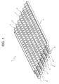
- the reference number 1 designates as a whole a photovoltaic panel constituted by a series of photovoltaic modules 2 set parallel to one another and alongside one another, which are mounted so that they can turn within a supporting frame 3 about respective axes of articulation 4 parallel to one another.
- each module 2 comprises an aligned series of photovoltaic cells 5 mounted on an elongated plate 6 having its two opposite ends supported in an articulated way by two opposite sides of the frame 3 about the respective axis of articulation 4.
- the plate 6 in turn supports a substantially channel-shaped covering structure, bearing on its top surface a distribution of concentric lenses 8 each associated to a respective photovoltaic cell 5.
- each module 2 is oriented about the respective axis of articulation 4 so as to track the sun.
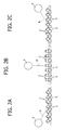
- the movement obtained is such that for each position of the sun the plane of each plate 6 bearing the photovoltaic cells 5 remains substantially orthogonal to the direction of the direct solar radiation, designated by R in Figures 2A-2C.
- the axes of articulation 4 of the modules 2 are oriented substantially in a north - south direction so as to enable the modules 2 to track the daily motion of the sun. It is, however, possible to envisage also an orientation of the entire frame 3 to enable tracking also of the seasonal movement of the sun.
- each module 2 associated to each module 2 is an actuator device 9 according to the present invention.
- an actuator device 9 that will control directly the tracking movement of one of the modules 3, and then to provide a transmission, for example of the pantograph type, for connection between the module 2, which is controlled directly by the actuator device, and the remaining modules 2, in such a way as to force the latter to perform a movement identical to that of the module 2 controlled by the actuator device.
- each actuator device 9 comprises a cylindrical body 10 functioning as solar collector rigidly mounted in cantilever fashion on the frame 3, with an end flange 10a thereof fixed to said frame.
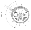
- One sector 11 of the wall of the collector 10 corresponding to an angular range A that is sufficiently wide as to cover the entire arc of movement of the sun, is made of transparent material, for example of transparent plastic material, and has its outer surface shaped so as to define a plurality of lenses 12 shaped and sized in such a way that for each position of the sun only one of said lenses 12 is able to concentrate the direct solar radiation R on a shape-memory element 13 set at the centre of the collector 10.
- the shape-memory element 13 is constituted by a torsion bar having one end 13a rigidly connected to a bottom wall 10b of the wall of the collector 10, and is consequently fixed in position.
- the opposite end 13b of the bar is instead connected in rotation to a tubular appendage 14a projecting from one end of an elongated shield 14 shaped like the sector of a cylindrical wall and set concentrically within the collector 10 (see, in particular, Figure 4).
- the cylindrical wall of the shield 14 is made of any material, for example, of plastic material, that is not transparent or in any case such as to intercept solar radiation.
- a spiral spring 15 is set between the collector member 10 and the shield 14 so as to recall the latter towards an end-of-travel position in which the shield is in a position totally lying outside the angular range A.
- the return spring 15 is pre-arranged for pushing the shutter 14 in a clockwise direction from the position in which it is represented in said figure towards a position set at the right with respect to the sector A.
- the structure of the shield 14 is in turn connected in rotation to the structure of the respective module 2 (see Figure 5).
- the shape-memory actuator element 13 is a torsion bar made of any shape-memory material chosen in such a way that, as the temperature increases above a transition value characteristic of the shape-memory element, the end 13b of the torsion bar rotates with respect to the end 13a anchored via the collector 10 to the structure of the frame 3.
- the direct radiation R is focused by a respective lens 12 of the collector 10 on the torsion bar 13, which is found in a position that coincides with the axis of the cylindrical wall of the collector 10.
- the arrangement is such that the light focused on the shape-memory actuator element causes an increase in temperature thereof above the transition value.
- the shape-memory element is pre-arranged in such a way that the rotation of the end 13b that occurs when the shape-memory element passes from a martensitic structure to an austenitic structure following upon overstepping of the transition value is potentially sufficient for bringing about a rotation of the shield 14 from its resting position as far as a position in which it comes to cover with its end edge 14', which faces forwards with reference to the direction of rotation, the last cylindrical lens 12 set at the end of the angular range A furthest away with respect to the resting position of the shield (i.e., the lens 12 illustrated furthest to the left in Figure 4).
- the lens 12' is once again able to focus the solar radiation on the shape-memory element so that the latter exceeds once again its transition temperature and again brings about a counterclockwise rotation of the shield 14.
- the phenomenon described above repeats cyclically, with successive oscillations of the shield 14 between the angular position P and the angular position Q. Basically then, the shield is kept on average in a position in which its edge 14' is aligned with the solar radiation R. Since, as has been seen, the structure of the shield 14 is connected in rotation to the structure of the respective module 2, also the module 2 will perform the same movements of oscillation maintaining itself on average aligned with the sun.
- the arrangement is, in fact, such that, when the edge 14' of the shield 14 is found in an angular position intermediate between the radial planes P and Q, the plane of the photovoltaic cells of the module 2 is substantially orthogonal to the direct radiation R.
- the shield will consequently continue to maintain the plane of the photovoltaic cells 5 of the respective module 2 substantially orthogonal to the direction of the sun, at the same time continuing to perform minor oscillations about said position.
- the collector 10 and the shape-memory material are designed so as to guarantee proper operation even with low values of solar radiation, for example, in the region of 200 W/m 2 .
- the excess of available energy in conditions of higher values of solar radiation, for example, in the region of 1000 W/m 2 will not damage the actuator in so far as it is intrinsically protected by the movement of the shield 14.
- hatches can be provided, in turn controlled by shape-memory elements, that will enable an automatic change of air should the temperature within the collector overstep the conditions of proper operation.
- a shape-memory actuator element constituted by a torsion bar it is also possible to envisage a shape-memory actuator element constituted, for instance, by a linearly mobile element, for example, a wire that reduces its length when it is activated, in which case mechanisms of transmission must be envisaged for converting the linear motion of the shape-memory actuator into a rotation of the shield 14 (for example, a rack-and-pinion transmission).
- heating of the shape-memory actuator 13 can be obtained either by focusing the direct solar radiation (Figure 7A) or by focusing the direct solar radiation and then reflecting it within the collector ( Figure 7B), or else indirectly, by focusing the direct solar radiation on the wall of the collector, which functions as black body and determines an increase in the temperature of its internal environment.
- One of the two tracking modules may not be of the type forming subject of the present invention.
- the collector 10 can be made with techniques in themselves known in the field of solar collectors, for example in the form of a double tube, or with vacuum gap, or else using special glasses in order to reduce the losses of heat and increase efficiency of the collector.
Landscapes
- Engineering & Computer Science (AREA)
- Chemical & Material Sciences (AREA)
- Combustion & Propulsion (AREA)
- Mechanical Engineering (AREA)
- General Engineering & Computer Science (AREA)
- Life Sciences & Earth Sciences (AREA)
- Sustainable Development (AREA)
- Sustainable Energy (AREA)
- Physics & Mathematics (AREA)
- Thermal Sciences (AREA)
- Photovoltaic Devices (AREA)
Abstract
Description
- The present invention relates to devices designed to impart a sun-tracking movement on an orientable member, in particular a solar generator, of the type comprising at least one shape-memory element activated by the heat generated by solar radiation.
- A device of the type referred to above is, for example, known from the
document No. JP-A-11125765 - The purpose of the present invention is to provide a device of the type specified above that will be particularly simple and efficient in operation.
- With a view to achieving said purpose, the subject of the invention is an actuator device having the characteristics referred to above and further characterized in that the shape-memory element is surrounded by a distribution of lenses designed always to focus direct solar radiation directly or indirectly on the shape-memory element as the position of the sun varies, said device further comprising a sun-shielding member connected in rotation to the orientable member and controlled by the shape-memory element in such a way that it moves, as a result of activation of the shape-memory element due to solar radiation, as far as a position in which it shields the shape-memory element with respect to the direct solar radiation, with consequent de-activation of the shape-memory element and return of the shielding member into a position in which it uncovers the shape-memory element again with respect to the direct solar radiation, thus determining re-activation of the shape-memory element, with the result that the shielding member oscillates continuously about a position that corresponds to a desired alignment of the orientable member with the sun, and that follows the sun in its path.
- The invention will now be described with reference to the annexed plate of drawings, which is provided purely by of non-limiting example and in which:
- Figure 1 is a perspective view of a solar converter unit provided with a plurality of actuator devices according to the invention;
- Figures 2A, 2B, 2C are schematic cross-sectional views that show three different positions assumed by the modules constituting the unit of Figure 1, as the position of the sun varies;
- Figures 3-5 are, respectively, an exploded perspective view, a partially sectioned perspective view, and a schematic cross-sectional view of an actuator device according to the invention;
- Figure 6 is a further perspective view of the actuator device according to the invention; and
- Figures 7A, 7B, 7C are cross-sectional views of the actuator device, which show different modes of heating of the shape-memory element.
- In the plate of drawings, the
reference number 1 designates as a whole a photovoltaic panel constituted by a series ofphotovoltaic modules 2 set parallel to one another and alongside one another, which are mounted so that they can turn within a supportingframe 3 about respective axes ofarticulation 4 parallel to one another. - As may be seen in particular in Figure 6, each
module 2 comprises an aligned series ofphotovoltaic cells 5 mounted on anelongated plate 6 having its two opposite ends supported in an articulated way by two opposite sides of theframe 3 about the respective axis ofarticulation 4. Theplate 6 in turn supports a substantially channel-shaped covering structure, bearing on its top surface a distribution ofconcentric lenses 8 each associated to a respectivephotovoltaic cell 5. As will emerge clearly from the ensuing description, as the position of the sun varies (see also Figures 2A, 2B, and 2C) eachmodule 2 is oriented about the respective axis ofarticulation 4 so as to track the sun. In particular, the movement obtained is such that for each position of the sun the plane of eachplate 6 bearing thephotovoltaic cells 5 remains substantially orthogonal to the direction of the direct solar radiation, designated by R in Figures 2A-2C. In the example illustrated, the axes ofarticulation 4 of themodules 2 are oriented substantially in a north - south direction so as to enable themodules 2 to track the daily motion of the sun. It is, however, possible to envisage also an orientation of theentire frame 3 to enable tracking also of the seasonal movement of the sun. - In order to obtain the sun-tracking movement of each
module 2, associated to eachmodule 2 is anactuator device 9 according to the present invention. Of course, it is also possible to envisage asingle actuator member 9 that will control directly the tracking movement of one of themodules 3, and then to provide a transmission, for example of the pantograph type, for connection between themodule 2, which is controlled directly by the actuator device, and theremaining modules 2, in such a way as to force the latter to perform a movement identical to that of themodule 2 controlled by the actuator device. - With reference in particular to Figures 3-5, each
actuator device 9 comprises acylindrical body 10 functioning as solar collector rigidly mounted in cantilever fashion on theframe 3, with an end flange 10a thereof fixed to said frame. Onesector 11 of the wall of thecollector 10, corresponding to an angular range A that is sufficiently wide as to cover the entire arc of movement of the sun, is made of transparent material, for example of transparent plastic material, and has its outer surface shaped so as to define a plurality oflenses 12 shaped and sized in such a way that for each position of the sun only one ofsaid lenses 12 is able to concentrate the direct solar radiation R on a shape-memory element 13 set at the centre of thecollector 10. - The shape-
memory element 13 is constituted by a torsion bar having oneend 13a rigidly connected to abottom wall 10b of the wall of thecollector 10, and is consequently fixed in position. Theopposite end 13b of the bar is instead connected in rotation to atubular appendage 14a projecting from one end of anelongated shield 14 shaped like the sector of a cylindrical wall and set concentrically within the collector 10 (see, in particular, Figure 4). The cylindrical wall of theshield 14 is made of any material, for example, of plastic material, that is not transparent or in any case such as to intercept solar radiation. Aspiral spring 15 is set between thecollector member 10 and theshield 14 so as to recall the latter towards an end-of-travel position in which the shield is in a position totally lying outside the angular range A. With reference to Figure 4, if the movement of the sun in said figure is in the counterclockwise direction, thereturn spring 15 is pre-arranged for pushing theshutter 14 in a clockwise direction from the position in which it is represented in said figure towards a position set at the right with respect to the sector A. - The structure of the
shield 14 is in turn connected in rotation to the structure of the respective module 2 (see Figure 5). - As has already been mentioned above, the shape-
memory actuator element 13 is a torsion bar made of any shape-memory material chosen in such a way that, as the temperature increases above a transition value characteristic of the shape-memory element, theend 13b of the torsion bar rotates with respect to theend 13a anchored via thecollector 10 to the structure of theframe 3. For each position of the sun S in the course of the day, the direct radiation R is focused by arespective lens 12 of thecollector 10 on thetorsion bar 13, which is found in a position that coincides with the axis of the cylindrical wall of thecollector 10. The arrangement is such that the light focused on the shape-memory actuator element causes an increase in temperature thereof above the transition value. The shape-memory element is pre-arranged in such a way that the rotation of theend 13b that occurs when the shape-memory element passes from a martensitic structure to an austenitic structure following upon overstepping of the transition value is potentially sufficient for bringing about a rotation of theshield 14 from its resting position as far as a position in which it comes to cover with its end edge 14', which faces forwards with reference to the direction of rotation, the lastcylindrical lens 12 set at the end of the angular range A furthest away with respect to the resting position of the shield (i.e., thelens 12 illustrated furthest to the left in Figure 4). Assuming that the sun is in the position S illustrated in Figure 4, the actual rotation of theshield 14 caused by activation of the shape-memory element 13 does not proceed as far as the final position described above and stops, instead, when theshield 14 intercepts thelens 12, which in said moment is focusing the direct radiation R coming from the sun on the shape-memory element. This occurs substantially when the edge 14' of the shield 14 (see Figure 4) comes to correspond to the radial plane designated by P in Figure 4. In said condition, the direct radiation R is no longer focused on the shape-memory actuator element 13, which consequently cools down to resume its resting condition. Theshield 14 thus tends to rotate in a clockwise direction (as viewed in Figure 4) returning to its resting position, under the thrust of thereturn spring 15. However, as soon as the shield has returned into the position that is illustrated in Figure 4, aligned with the radial plane designated by Q in Figure 4, the lens 12' is once again able to focus the solar radiation on the shape-memory element so that the latter exceeds once again its transition temperature and again brings about a counterclockwise rotation of theshield 14. The phenomenon described above repeats cyclically, with successive oscillations of theshield 14 between the angular position P and the angular position Q. Basically then, the shield is kept on average in a position in which its edge 14' is aligned with the solar radiation R. Since, as has been seen, the structure of theshield 14 is connected in rotation to the structure of therespective module 2, also themodule 2 will perform the same movements of oscillation maintaining itself on average aligned with the sun. The arrangement is, in fact, such that, when the edge 14' of theshield 14 is found in an angular position intermediate between the radial planes P and Q, the plane of the photovoltaic cells of themodule 2 is substantially orthogonal to the direct radiation R. - As the position of the sun varies, the shield will consequently continue to maintain the plane of the
photovoltaic cells 5 of therespective module 2 substantially orthogonal to the direction of the sun, at the same time continuing to perform minor oscillations about said position. - The
collector 10 and the shape-memory material are designed so as to guarantee proper operation even with low values of solar radiation, for example, in the region of 200 W/m2. The excess of available energy in conditions of higher values of solar radiation, for example, in the region of 1000 W/m2, will not damage the actuator in so far as it is intrinsically protected by the movement of theshield 14. - In addition, on the surface of the
collector 10 hatches can be provided, in turn controlled by shape-memory elements, that will enable an automatic change of air should the temperature within the collector overstep the conditions of proper operation. - Of course, even though the example illustrated makes use of a shape-memory actuator element constituted by a torsion bar, it is also possible to envisage a shape-memory actuator element constituted, for instance, by a linearly mobile element, for example, a wire that reduces its length when it is activated, in which case mechanisms of transmission must be envisaged for converting the linear motion of the shape-memory actuator into a rotation of the shield 14 (for example, a rack-and-pinion transmission).
- With reference once again to Figures 7A, 7B and 7C, heating of the shape-
memory actuator 13 can be obtained either by focusing the direct solar radiation (Figure 7A) or by focusing the direct solar radiation and then reflecting it within the collector (Figure 7B), or else indirectly, by focusing the direct solar radiation on the wall of the collector, which functions as black body and determines an increase in the temperature of its internal environment. - By combining two trackers on two orthogonal axes of the panel it is possible to track the sun both on a daily basis and on a seasonal basis. One of the two tracking modules may not be of the type forming subject of the present invention. For example, it is possible to envisage a tracking module that operates on a daily basis according to the invention and a tracking module that operates on a seasonal basis controlled by an electric motor.
- In addition, the
collector 10 can be made with techniques in themselves known in the field of solar collectors, for example in the form of a double tube, or with vacuum gap, or else using special glasses in order to reduce the losses of heat and increase efficiency of the collector. - Of course, without prejudice to the principle of the invention, the details of construction and the embodiments may vary widely with respect to what is described and illustrated herein purely by way of example, without thereby departing from the scope of the present invention.
Claims (13)
- A shape-memory actuator device for imparting a sun-tracking movement on an orientable member (2), comprising at least one shape-memory element (13) activated by the heat generated by the solar radiation,
characterized in that the shape-memory element (13) is surrounded by a distribution of lenses (12) designed to focus always, as the position of the sun varies, the direct solar radiation directly or indirectly on the shape-memory element (13), said device further comprising a sun-shielding member (14), connected in rotation to the orientable member (2) and controlled by the shape-memory element (13) in such a way that it is moved, as a result of activation of the shape-memory element (13) due to the solar radiation, as far as a position in which it shields the shape-memory element with respect to the direct solar radiation, with consequent de-activation of the shape-memory element (13) and return of the shielding member (14) into a position in which it uncovers again the shape-memory element (13) with respect to the direct solar radiation, thus determining re-activation of the shape-memory element, with the result that the shielding member (14) oscillates continuously about a position that corresponds to a desired alignment of the orientable member with the sun and that follows the sun in its path. - The actuator device according to Claim 1,
characterized in that means (15) are provided for recalling the shielding member (14) to an end-of-travel position. - The actuator device according to Claim 2,
characterized in that said return means are constituted by a spring (15). - The actuator device according to Claim 1,
characterized in that the aforesaid distribution of lenses (12) is defined on an angular sector (A) of the wall of a cylindrical collector (10), and that the shape-memory element (13) is set inside said cylindrical collector. - The actuator device according to Claim 4,
characterized in that the shape-memory element (13) is in the form of a torsion bar, with one end (13a) anchored to the body of the collector (10) and the opposite end (13b) connected in rotation to the aforesaid shielding member (14). - The actuator device according to Claim 4,
characterized in that the shielding member (14) comprises a cylindrical wall that is concentric with the cylindrical wall of the collector (10) and is set inside it. - The actuator device according to Claim 6,
characterized in that the body of the collector (10) is fixed to a frame (3), mounted oscillating on which is the aforesaid orientable member (2) and in that said shielding member (14) is connected in rotation to said orientable member (2). - The actuator device according to any one of the preceding claims, characterized in that said orientable member is constituted by a photovoltaic module (2) comprising an elongated wall (6) having its opposite ends supported in an articulated way on a frame (3) and carrying thereon an aligned distribution of photovoltaic cells (5), said elongated plate (6) supporting in turn a covering structure including a distribution of focusing lenses (8), each of which is associated to a photovoltaic cell (5) for concentrating on the latter the solar radiation, the arrangement being such that the aforesaid actuator device constantly maintains the shielding member (14) in a position that corresponds to a position of the aforesaid plate (6) carrying the photovoltaic cells (5) orthogonal to the direct radiation (R) of the sun.
- The actuator device according to Claim 4,
characterized in that the wall of the collector has openings controlled by hatches, which can open automatically to set in communication the internal environment of the collector with the external environment when the temperature within of the collector exceeds a pre-set value. - The actuator device according to Claim 9, characterized in that said hatches are controlled by shape-memory actuator means sensitive to the temperature inside the collector.
- The actuator device according to Claim 1, characterized in that said shape-memory actuator element (13) is constituted by an elongated element, which decreases in length as a transition temperature is exceeded, and in that a mechanical transmission is provided designed to convert the linear movement of the shape-memory element into a rotary movement of the aforesaid shielding member.
- A device according to Claim 4, characterized in that the aforesaid collector (10) is pre-arranged for heating the shape-memory element (13) by direct focusing of the solar radiation via said lenses (12) set on top of the shape-memory element (13), or else by focusing of the direct radiation of the sun on the internal wall of the collector (10), which functions as black body designed to increase its internal temperature.
- The device according to Claim 4, characterized in that the aforesaid collector (10) is pre-arranged for heating the shape-memory element (13) via said lenses (12), directing the direct radiation of the sun on a portion of the internal surface of the collector, said surface being reflective and focusing on the shape-memory element (13).
Priority Applications (3)
| Application Number | Priority Date | Filing Date | Title |
|---|---|---|---|
| DE602006004068T DE602006004068D1 (en) | 2006-10-18 | 2006-10-18 | A shape memory alloy actuator in a sun tracking device, in particular a solar panel |
| EP06425714A EP1914421B1 (en) | 2006-10-18 | 2006-10-18 | Shape memory actuator device for imparting a sun tracking movement to an orientable member, in particular a solar generator |
| AT06425714T ATE416309T1 (en) | 2006-10-18 | 2006-10-18 | SHAPE MEMORY ALLOY ACTUATOR IN A SOLAR TRACKING DEVICE, PARTICULARLY A SOLAR COLLECTOR |
Applications Claiming Priority (1)
| Application Number | Priority Date | Filing Date | Title |
|---|---|---|---|
| EP06425714A EP1914421B1 (en) | 2006-10-18 | 2006-10-18 | Shape memory actuator device for imparting a sun tracking movement to an orientable member, in particular a solar generator |
Publications (2)
| Publication Number | Publication Date |
|---|---|
| EP1914421A1 true EP1914421A1 (en) | 2008-04-23 |
| EP1914421B1 EP1914421B1 (en) | 2008-12-03 |
Family
ID=37605696
Family Applications (1)
| Application Number | Title | Priority Date | Filing Date |
|---|---|---|---|
| EP06425714A Not-in-force EP1914421B1 (en) | 2006-10-18 | 2006-10-18 | Shape memory actuator device for imparting a sun tracking movement to an orientable member, in particular a solar generator |
Country Status (3)
| Country | Link |
|---|---|
| EP (1) | EP1914421B1 (en) |
| AT (1) | ATE416309T1 (en) |
| DE (1) | DE602006004068D1 (en) |
Cited By (6)
| Publication number | Priority date | Publication date | Assignee | Title |
|---|---|---|---|---|
| WO2013149103A1 (en) * | 2012-03-30 | 2013-10-03 | Perryman Virgil Dewitt Jr | Non-tracking solar radiation collector |
| US8938965B1 (en) * | 2011-05-27 | 2015-01-27 | The United States Of America As Represented By The Administrator Of The National Aeronautics And Space Administration | Thermal powered reciprocating-force motor |
| US10119728B2 (en) | 2012-03-09 | 2018-11-06 | Virgil Dewitt Perryman, Jr. | Solar energy collection and storage |
| CN110061689A (en) * | 2019-05-21 | 2019-07-26 | 陆永成 | Automatic solar power system day by day |
| CN110061690A (en) * | 2019-05-21 | 2019-07-26 | 陆永成 | A kind of automatic method day by day of solar panel |
| CN110095767A (en) * | 2019-05-08 | 2019-08-06 | 哈尔滨工业大学 | A kind of extraterrestrial target imaging simulation face element blanking method |
Citations (4)
| Publication number | Priority date | Publication date | Assignee | Title |
|---|---|---|---|---|
| JPS59119144A (en) * | 1982-12-24 | 1984-07-10 | Toshiba Corp | Solar heat collector |
| JPS60205151A (en) * | 1984-03-29 | 1985-10-16 | Toshiba Electric Equip Corp | Sun tracking device |
| WO1999061792A1 (en) * | 1998-05-26 | 1999-12-02 | Lockheed Martin Corporation | Constant force spring actuator |
| US6298662B1 (en) * | 1998-04-06 | 2001-10-09 | Alcatel | Device for controlling a relative rotation between two articulated elements and a deployable mechanical structure, particularly for a space vehicle, using at least one device of this type |
-
2006
- 2006-10-18 AT AT06425714T patent/ATE416309T1/en not_active IP Right Cessation
- 2006-10-18 EP EP06425714A patent/EP1914421B1/en not_active Not-in-force
- 2006-10-18 DE DE602006004068T patent/DE602006004068D1/en active Active
Patent Citations (4)
| Publication number | Priority date | Publication date | Assignee | Title |
|---|---|---|---|---|
| JPS59119144A (en) * | 1982-12-24 | 1984-07-10 | Toshiba Corp | Solar heat collector |
| JPS60205151A (en) * | 1984-03-29 | 1985-10-16 | Toshiba Electric Equip Corp | Sun tracking device |
| US6298662B1 (en) * | 1998-04-06 | 2001-10-09 | Alcatel | Device for controlling a relative rotation between two articulated elements and a deployable mechanical structure, particularly for a space vehicle, using at least one device of this type |
| WO1999061792A1 (en) * | 1998-05-26 | 1999-12-02 | Lockheed Martin Corporation | Constant force spring actuator |
Cited By (7)
| Publication number | Priority date | Publication date | Assignee | Title |
|---|---|---|---|---|
| US8938965B1 (en) * | 2011-05-27 | 2015-01-27 | The United States Of America As Represented By The Administrator Of The National Aeronautics And Space Administration | Thermal powered reciprocating-force motor |
| US10119728B2 (en) | 2012-03-09 | 2018-11-06 | Virgil Dewitt Perryman, Jr. | Solar energy collection and storage |
| WO2013149103A1 (en) * | 2012-03-30 | 2013-10-03 | Perryman Virgil Dewitt Jr | Non-tracking solar radiation collector |
| CN110095767A (en) * | 2019-05-08 | 2019-08-06 | 哈尔滨工业大学 | A kind of extraterrestrial target imaging simulation face element blanking method |
| CN110095767B (en) * | 2019-05-08 | 2022-05-20 | 哈尔滨工业大学 | Spatial target imaging simulation binning method |
| CN110061689A (en) * | 2019-05-21 | 2019-07-26 | 陆永成 | Automatic solar power system day by day |
| CN110061690A (en) * | 2019-05-21 | 2019-07-26 | 陆永成 | A kind of automatic method day by day of solar panel |
Also Published As
| Publication number | Publication date |
|---|---|
| ATE416309T1 (en) | 2008-12-15 |
| EP1914421B1 (en) | 2008-12-03 |
| DE602006004068D1 (en) | 2009-01-15 |
Similar Documents
| Publication | Publication Date | Title |
|---|---|---|
| US6971756B2 (en) | Apparatus for collecting and converting radiant energy | |
| KR100971160B1 (en) | Solar linear power plant | |
| US20080295883A1 (en) | Adaptive solar concentrator system | |
| US20110259319A1 (en) | Solar Energy Absorber | |
| US20090107542A1 (en) | Solar collector stabilized by cables and a compression element | |
| WO2009063416A2 (en) | Thin and efficient collecting optics for solar system | |
| KR20130057992A (en) | Solar heat collecting system | |
| US20100218817A1 (en) | Solar concentration system | |
| CA1265397A (en) | Heliotropic solar heat collector system | |
| Natarajan et al. | Experimental analysis of a two‐axis tracking system for solar parabolic dish collector | |
| US20110088684A1 (en) | Solar Energy Concentrator | |
| EP1914421B1 (en) | Shape memory actuator device for imparting a sun tracking movement to an orientable member, in particular a solar generator | |
| WO2022150919A1 (en) | Dual axis solar array tracker | |
| US9587858B2 (en) | Solar collector | |
| US10185120B2 (en) | Movement control apparatus for heliostat device | |
| EP2280421B1 (en) | Solar receiver for a solar concentrator with a linear focus | |
| EP3499586A1 (en) | Solar energy concentrator with movable mirrors for use in flat solar thermal collectors or in static photovoltaic modules | |
| JP4978848B2 (en) | Concentrating solar power generation system | |
| WO2012079143A1 (en) | Solar energy concentrator | |
| CN103955230A (en) | Light condensing power adjusting device and solar power generation device | |
| JP6115917B2 (en) | Solar tracking device and solar tracking solar cell | |
| JP2007324387A (en) | Automatic solar tracking device | |
| KR101968964B1 (en) | Flat concentrating photovoltaic apparatus | |
| RU2661169C1 (en) | Multi-mirror solar plant with the common drive of the orientation system | |
| US20210159847A1 (en) | Tracking device |
Legal Events
| Date | Code | Title | Description |
|---|---|---|---|
| PUAI | Public reference made under article 153(3) epc to a published international application that has entered the european phase |
Free format text: ORIGINAL CODE: 0009012 |
|
| 17P | Request for examination filed |
Effective date: 20070607 |
|
| AK | Designated contracting states |
Kind code of ref document: A1 Designated state(s): AT BE BG CH CY CZ DE DK EE ES FI FR GB GR HU IE IS IT LI LT LU LV MC NL PL PT RO SE SI SK TR |
|
| AX | Request for extension of the european patent |
Extension state: AL BA HR MK RS |
|
| GRAP | Despatch of communication of intention to grant a patent |
Free format text: ORIGINAL CODE: EPIDOSNIGR1 |
|
| GRAS | Grant fee paid |
Free format text: ORIGINAL CODE: EPIDOSNIGR3 |
|
| GRAA | (expected) grant |
Free format text: ORIGINAL CODE: 0009210 |
|
| AK | Designated contracting states |
Kind code of ref document: B1 Designated state(s): AT BE BG CH CY CZ DE DK EE ES FI FR GB GR HU IE IS IT LI LT LU LV MC NL PL PT RO SE SI SK TR |
|
| REG | Reference to a national code |
Ref country code: GB Ref legal event code: FG4D |
|
| REG | Reference to a national code |
Ref country code: CH Ref legal event code: EP |
|
| AKX | Designation fees paid |
Designated state(s): AT BE BG CH CY CZ DE DK EE ES FI FR GB GR HU IE IS IT LI LT LU LV MC NL PL PT RO SE SI SK TR |
|
| REG | Reference to a national code |
Ref country code: IE Ref legal event code: FG4D |
|
| REF | Corresponds to: |
Ref document number: 602006004068 Country of ref document: DE Date of ref document: 20090115 Kind code of ref document: P |
|
| PG25 | Lapsed in a contracting state [announced via postgrant information from national office to epo] |
Ref country code: LT Free format text: LAPSE BECAUSE OF FAILURE TO SUBMIT A TRANSLATION OF THE DESCRIPTION OR TO PAY THE FEE WITHIN THE PRESCRIBED TIME-LIMIT Effective date: 20081203 Ref country code: ES Free format text: LAPSE BECAUSE OF FAILURE TO SUBMIT A TRANSLATION OF THE DESCRIPTION OR TO PAY THE FEE WITHIN THE PRESCRIBED TIME-LIMIT Effective date: 20090314 |
|
| NLV1 | Nl: lapsed or annulled due to failure to fulfill the requirements of art. 29p and 29m of the patents act | ||
| PG25 | Lapsed in a contracting state [announced via postgrant information from national office to epo] |
Ref country code: SI Free format text: LAPSE BECAUSE OF FAILURE TO SUBMIT A TRANSLATION OF THE DESCRIPTION OR TO PAY THE FEE WITHIN THE PRESCRIBED TIME-LIMIT Effective date: 20081203 Ref country code: FI Free format text: LAPSE BECAUSE OF FAILURE TO SUBMIT A TRANSLATION OF THE DESCRIPTION OR TO PAY THE FEE WITHIN THE PRESCRIBED TIME-LIMIT Effective date: 20081203 Ref country code: PL Free format text: LAPSE BECAUSE OF FAILURE TO SUBMIT A TRANSLATION OF THE DESCRIPTION OR TO PAY THE FEE WITHIN THE PRESCRIBED TIME-LIMIT Effective date: 20081203 Ref country code: LV Free format text: LAPSE BECAUSE OF FAILURE TO SUBMIT A TRANSLATION OF THE DESCRIPTION OR TO PAY THE FEE WITHIN THE PRESCRIBED TIME-LIMIT Effective date: 20081203 Ref country code: NL Free format text: LAPSE BECAUSE OF FAILURE TO SUBMIT A TRANSLATION OF THE DESCRIPTION OR TO PAY THE FEE WITHIN THE PRESCRIBED TIME-LIMIT Effective date: 20081203 |
|
| PG25 | Lapsed in a contracting state [announced via postgrant information from national office to epo] |
Ref country code: BE Free format text: LAPSE BECAUSE OF FAILURE TO SUBMIT A TRANSLATION OF THE DESCRIPTION OR TO PAY THE FEE WITHIN THE PRESCRIBED TIME-LIMIT Effective date: 20081203 Ref country code: RO Free format text: LAPSE BECAUSE OF FAILURE TO SUBMIT A TRANSLATION OF THE DESCRIPTION OR TO PAY THE FEE WITHIN THE PRESCRIBED TIME-LIMIT Effective date: 20081203 Ref country code: BG Free format text: LAPSE BECAUSE OF FAILURE TO SUBMIT A TRANSLATION OF THE DESCRIPTION OR TO PAY THE FEE WITHIN THE PRESCRIBED TIME-LIMIT Effective date: 20090303 Ref country code: EE Free format text: LAPSE BECAUSE OF FAILURE TO SUBMIT A TRANSLATION OF THE DESCRIPTION OR TO PAY THE FEE WITHIN THE PRESCRIBED TIME-LIMIT Effective date: 20081203 |
|
| PG25 | Lapsed in a contracting state [announced via postgrant information from national office to epo] |
Ref country code: SE Free format text: LAPSE BECAUSE OF FAILURE TO SUBMIT A TRANSLATION OF THE DESCRIPTION OR TO PAY THE FEE WITHIN THE PRESCRIBED TIME-LIMIT Effective date: 20090303 Ref country code: PT Free format text: LAPSE BECAUSE OF FAILURE TO SUBMIT A TRANSLATION OF THE DESCRIPTION OR TO PAY THE FEE WITHIN THE PRESCRIBED TIME-LIMIT Effective date: 20090504 Ref country code: CZ Free format text: LAPSE BECAUSE OF FAILURE TO SUBMIT A TRANSLATION OF THE DESCRIPTION OR TO PAY THE FEE WITHIN THE PRESCRIBED TIME-LIMIT Effective date: 20081203 Ref country code: AT Free format text: LAPSE BECAUSE OF FAILURE TO SUBMIT A TRANSLATION OF THE DESCRIPTION OR TO PAY THE FEE WITHIN THE PRESCRIBED TIME-LIMIT Effective date: 20081203 Ref country code: IS Free format text: LAPSE BECAUSE OF FAILURE TO SUBMIT A TRANSLATION OF THE DESCRIPTION OR TO PAY THE FEE WITHIN THE PRESCRIBED TIME-LIMIT Effective date: 20090403 |
|
| PG25 | Lapsed in a contracting state [announced via postgrant information from national office to epo] |
Ref country code: SK Free format text: LAPSE BECAUSE OF FAILURE TO SUBMIT A TRANSLATION OF THE DESCRIPTION OR TO PAY THE FEE WITHIN THE PRESCRIBED TIME-LIMIT Effective date: 20081203 |
|
| PLBE | No opposition filed within time limit |
Free format text: ORIGINAL CODE: 0009261 |
|
| STAA | Information on the status of an ep patent application or granted ep patent |
Free format text: STATUS: NO OPPOSITION FILED WITHIN TIME LIMIT |
|
| PG25 | Lapsed in a contracting state [announced via postgrant information from national office to epo] |
Ref country code: DK Free format text: LAPSE BECAUSE OF FAILURE TO SUBMIT A TRANSLATION OF THE DESCRIPTION OR TO PAY THE FEE WITHIN THE PRESCRIBED TIME-LIMIT Effective date: 20081203 |
|
| 26N | No opposition filed |
Effective date: 20090904 |
|
| PG25 | Lapsed in a contracting state [announced via postgrant information from national office to epo] |
Ref country code: MC Free format text: LAPSE BECAUSE OF NON-PAYMENT OF DUE FEES Effective date: 20091031 |
|
| REG | Reference to a national code |
Ref country code: IE Ref legal event code: MM4A |
|
| PG25 | Lapsed in a contracting state [announced via postgrant information from national office to epo] |
Ref country code: GR Free format text: LAPSE BECAUSE OF FAILURE TO SUBMIT A TRANSLATION OF THE DESCRIPTION OR TO PAY THE FEE WITHIN THE PRESCRIBED TIME-LIMIT Effective date: 20090304 Ref country code: IE Free format text: LAPSE BECAUSE OF NON-PAYMENT OF DUE FEES Effective date: 20091018 |
|
| PG25 | Lapsed in a contracting state [announced via postgrant information from national office to epo] |
Ref country code: LU Free format text: LAPSE BECAUSE OF NON-PAYMENT OF DUE FEES Effective date: 20091018 |
|
| REG | Reference to a national code |
Ref country code: CH Ref legal event code: PL |
|
| GBPC | Gb: european patent ceased through non-payment of renewal fee |
Effective date: 20101018 |
|
| PG25 | Lapsed in a contracting state [announced via postgrant information from national office to epo] |
Ref country code: HU Free format text: LAPSE BECAUSE OF FAILURE TO SUBMIT A TRANSLATION OF THE DESCRIPTION OR TO PAY THE FEE WITHIN THE PRESCRIBED TIME-LIMIT Effective date: 20090604 |
|
| PG25 | Lapsed in a contracting state [announced via postgrant information from national office to epo] |
Ref country code: CH Free format text: LAPSE BECAUSE OF NON-PAYMENT OF DUE FEES Effective date: 20101031 Ref country code: LI Free format text: LAPSE BECAUSE OF NON-PAYMENT OF DUE FEES Effective date: 20101031 |
|
| PG25 | Lapsed in a contracting state [announced via postgrant information from national office to epo] |
Ref country code: GB Free format text: LAPSE BECAUSE OF NON-PAYMENT OF DUE FEES Effective date: 20101018 Ref country code: TR Free format text: LAPSE BECAUSE OF FAILURE TO SUBMIT A TRANSLATION OF THE DESCRIPTION OR TO PAY THE FEE WITHIN THE PRESCRIBED TIME-LIMIT Effective date: 20081203 |
|
| PG25 | Lapsed in a contracting state [announced via postgrant information from national office to epo] |
Ref country code: CY Free format text: LAPSE BECAUSE OF FAILURE TO SUBMIT A TRANSLATION OF THE DESCRIPTION OR TO PAY THE FEE WITHIN THE PRESCRIBED TIME-LIMIT Effective date: 20081203 |
|
| PGFP | Annual fee paid to national office [announced via postgrant information from national office to epo] |
Ref country code: FR Payment date: 20141008 Year of fee payment: 9 Ref country code: DE Payment date: 20141014 Year of fee payment: 9 |
|
| PGFP | Annual fee paid to national office [announced via postgrant information from national office to epo] |
Ref country code: IT Payment date: 20141007 Year of fee payment: 9 |
|
| REG | Reference to a national code |
Ref country code: DE Ref legal event code: R119 Ref document number: 602006004068 Country of ref document: DE |
|
| PG25 | Lapsed in a contracting state [announced via postgrant information from national office to epo] |
Ref country code: DE Free format text: LAPSE BECAUSE OF NON-PAYMENT OF DUE FEES Effective date: 20160503 Ref country code: IT Free format text: LAPSE BECAUSE OF NON-PAYMENT OF DUE FEES Effective date: 20151018 |
|
| REG | Reference to a national code |
Ref country code: FR Ref legal event code: ST Effective date: 20160630 |
|
| PG25 | Lapsed in a contracting state [announced via postgrant information from national office to epo] |
Ref country code: FR Free format text: LAPSE BECAUSE OF NON-PAYMENT OF DUE FEES Effective date: 20151102 |