EP1914109A1 - Sliding-type automobile seat - Google Patents
Sliding-type automobile seat Download PDFInfo
- Publication number
- EP1914109A1 EP1914109A1 EP06746644A EP06746644A EP1914109A1 EP 1914109 A1 EP1914109 A1 EP 1914109A1 EP 06746644 A EP06746644 A EP 06746644A EP 06746644 A EP06746644 A EP 06746644A EP 1914109 A1 EP1914109 A1 EP 1914109A1
- Authority
- EP
- European Patent Office
- Prior art keywords
- operating lever
- seat
- lock
- mechanisms
- engaging
- Prior art date
- Legal status (The legal status is an assumption and is not a legal conclusion. Google has not performed a legal analysis and makes no representation as to the accuracy of the status listed.)
- Withdrawn
Links
Images




Classifications
-
- B—PERFORMING OPERATIONS; TRANSPORTING
- B60—VEHICLES IN GENERAL
- B60N—SEATS SPECIALLY ADAPTED FOR VEHICLES; VEHICLE PASSENGER ACCOMMODATION NOT OTHERWISE PROVIDED FOR
- B60N2/00—Seats specially adapted for vehicles; Arrangement or mounting of seats in vehicles
- B60N2/02—Seats specially adapted for vehicles; Arrangement or mounting of seats in vehicles the seat or part thereof being movable, e.g. adjustable
- B60N2/04—Seats specially adapted for vehicles; Arrangement or mounting of seats in vehicles the seat or part thereof being movable, e.g. adjustable the whole seat being movable
- B60N2/06—Seats specially adapted for vehicles; Arrangement or mounting of seats in vehicles the seat or part thereof being movable, e.g. adjustable the whole seat being movable slidable
- B60N2/07—Slide construction
- B60N2/0702—Slide construction characterised by its cross-section
- B60N2/0705—Slide construction characterised by its cross-section omega-shaped
-
- B—PERFORMING OPERATIONS; TRANSPORTING
- B60—VEHICLES IN GENERAL
- B60N—SEATS SPECIALLY ADAPTED FOR VEHICLES; VEHICLE PASSENGER ACCOMMODATION NOT OTHERWISE PROVIDED FOR
- B60N2/00—Seats specially adapted for vehicles; Arrangement or mounting of seats in vehicles
- B60N2/02—Seats specially adapted for vehicles; Arrangement or mounting of seats in vehicles the seat or part thereof being movable, e.g. adjustable
- B60N2/04—Seats specially adapted for vehicles; Arrangement or mounting of seats in vehicles the seat or part thereof being movable, e.g. adjustable the whole seat being movable
- B60N2/06—Seats specially adapted for vehicles; Arrangement or mounting of seats in vehicles the seat or part thereof being movable, e.g. adjustable the whole seat being movable slidable
- B60N2/08—Seats specially adapted for vehicles; Arrangement or mounting of seats in vehicles the seat or part thereof being movable, e.g. adjustable the whole seat being movable slidable characterised by the locking device
- B60N2/0812—Location of the latch
- B60N2/0818—Location of the latch inside the rail
-
- B—PERFORMING OPERATIONS; TRANSPORTING
- B60—VEHICLES IN GENERAL
- B60N—SEATS SPECIALLY ADAPTED FOR VEHICLES; VEHICLE PASSENGER ACCOMMODATION NOT OTHERWISE PROVIDED FOR
- B60N2/00—Seats specially adapted for vehicles; Arrangement or mounting of seats in vehicles
- B60N2/02—Seats specially adapted for vehicles; Arrangement or mounting of seats in vehicles the seat or part thereof being movable, e.g. adjustable
- B60N2/04—Seats specially adapted for vehicles; Arrangement or mounting of seats in vehicles the seat or part thereof being movable, e.g. adjustable the whole seat being movable
- B60N2/06—Seats specially adapted for vehicles; Arrangement or mounting of seats in vehicles the seat or part thereof being movable, e.g. adjustable the whole seat being movable slidable
- B60N2/08—Seats specially adapted for vehicles; Arrangement or mounting of seats in vehicles the seat or part thereof being movable, e.g. adjustable the whole seat being movable slidable characterised by the locking device
- B60N2/0831—Movement of the latch
- B60N2/0837—Movement of the latch pivoting
- B60N2/085—Movement of the latch pivoting about a transversal axis
-
- B—PERFORMING OPERATIONS; TRANSPORTING
- B60—VEHICLES IN GENERAL
- B60N—SEATS SPECIALLY ADAPTED FOR VEHICLES; VEHICLE PASSENGER ACCOMMODATION NOT OTHERWISE PROVIDED FOR
- B60N2/00—Seats specially adapted for vehicles; Arrangement or mounting of seats in vehicles
- B60N2/02—Seats specially adapted for vehicles; Arrangement or mounting of seats in vehicles the seat or part thereof being movable, e.g. adjustable
- B60N2/04—Seats specially adapted for vehicles; Arrangement or mounting of seats in vehicles the seat or part thereof being movable, e.g. adjustable the whole seat being movable
- B60N2/06—Seats specially adapted for vehicles; Arrangement or mounting of seats in vehicles the seat or part thereof being movable, e.g. adjustable the whole seat being movable slidable
- B60N2/08—Seats specially adapted for vehicles; Arrangement or mounting of seats in vehicles the seat or part thereof being movable, e.g. adjustable the whole seat being movable slidable characterised by the locking device
- B60N2/0831—Movement of the latch
- B60N2/0862—Movement of the latch sliding
- B60N2/0875—Movement of the latch sliding in a vertical direction
-
- B—PERFORMING OPERATIONS; TRANSPORTING
- B60—VEHICLES IN GENERAL
- B60N—SEATS SPECIALLY ADAPTED FOR VEHICLES; VEHICLE PASSENGER ACCOMMODATION NOT OTHERWISE PROVIDED FOR
- B60N2/00—Seats specially adapted for vehicles; Arrangement or mounting of seats in vehicles
- B60N2/02—Seats specially adapted for vehicles; Arrangement or mounting of seats in vehicles the seat or part thereof being movable, e.g. adjustable
- B60N2/04—Seats specially adapted for vehicles; Arrangement or mounting of seats in vehicles the seat or part thereof being movable, e.g. adjustable the whole seat being movable
- B60N2/06—Seats specially adapted for vehicles; Arrangement or mounting of seats in vehicles the seat or part thereof being movable, e.g. adjustable the whole seat being movable slidable
- B60N2/08—Seats specially adapted for vehicles; Arrangement or mounting of seats in vehicles the seat or part thereof being movable, e.g. adjustable the whole seat being movable slidable characterised by the locking device
- B60N2/0881—Activation of the latches by the control mechanism
Definitions
- the present invention relates to a sliding-type automobile seat that can be slidingly moved, via a slide rail mechanism, forward and rearward in an automobile.
- this automobile seat includes a seat cushion frame 1 for a seat cushion thereof.
- the seat cushion frame 1 comprises a pair of spaced apart side frame sections 1a, a pan frame section 1b arranged and fixed between forward portions of the side frame sections 1a, and a rear frame section 1c arranged and fixed between rearward portions of the side frame sections 1a.
- the automobile seat can be slidingly moved forward and rearward in an automobile via a slide rail mechanism 2.
- the slide rail mechanism 2 comprises upper rails 2a attached to lower portions of the side frame sections 1a (only one side frame section 1a and only one upper rail 2a are shown in Fig. 2 ), and a pair of parallel lower rails 2b mounted on a floor surface of the automobile via stand leg portions 3a, 3b (only one lower rail 2b is shown in Fig. 2 ).
- the upper rails 2a are slidably engaged with the lower rails 2b as will be fully discussed hereinafter, whereby the seat can be slidingly moved forward and rearward in the automobile.
- each of the upper rails 2a (only one upper rail 2a is shown in Fig. 3 ) comprises a pair of members 20a, 20b of substantially J-shapes in vertical-section that are fixed back-to-back to a lower portion of a corresponding side frame section 1a of the automobile seat by a support pin 40 and hang downward from the side frame section 1a.
- Each of the lower rails 2b (only one lower rail 2b is shown in Fig. 3 ) has a longitudinal body 21 of a substantially U-shape in cross-section and is mounted on the floor surface of the automobile with an opening portion thereof facing upward.
- the lower rail body 21 includes inward bent flanges 22a, 22b of substantially L-shapes in cross-section that are bent inward from both ends of the substantially U-shaped lower rail body 21 in such a manner to allow a space to be produced between the inward bent flanges 22a, 22b.
- Each of the upper rail 2a is combined with a corresponding lower rail 2b by causing lower curved portions 20a', 20b' of the substantially J-shaped members 20a, 20b hanging downward from the side frame section 1a to be inserted into the substantially U-shaped lower rail body 21 through the space between the inward bent flanges 22a, 22b of the lower rail body 21, and causing tip end portions of the lower curved portions 20a', 20b' to be arranged inside the inward bent flanges 22a, 22b of the lower rail body 21.
- a plurality of rollers 23 are disposed (only one roller 23 is shown in Fig. 3 ), whereby the seat can be smoothly slid along the lower rails.
- the sliding-type automobile seat is provided with slide lock mechanisms for causing the seat to be locked at predetermined positions with respect to the lower rails 2b.
- the slide lock mechanisms include lock plates 4 arranged at side portions of the upper rails 2a (only one upper rail 2a and only one lock plate 4 are shown in Fig. 4 ).
- An operating lever 5 for releasing the seat from a locked condition is provided so as to be bridged between the lock plates 4.
- each of the lock plates 4 extends along the side portions of the substantially J-shaped members 20a, 20b of a corresponding upper rail 2a.
- the lock plate 4 is pivotally supported, at the substantially middle portion of its longitudinal direction, to the side portions of the substantially J-shaped members 20a, 20b of the upper rail 2a by the support pin 40, whereby the lock plate 4 is vertically swingable around the support pin 40.
- the lock plate 4 is formed, at its region adjacent a rear end portion thereof, with an elongated hole 41 vertically extending.
- a guide pin 42 projects from the side portion of the upper rail 2a and is inserted through the elongated hole 41 formed in the lock plate 4, so that the vertical swinging movement of the lock plate 4 is guided along the elongated hole 41.
- the lock plate 4 is urged by a coil spring 43 so as to be always pulled upward at the rear end portion thereof. More particularly, the coil spring 43 is retained at one end portion thereof to a protruding piece 43a provided at a corresponding side frame section 1a, and retained at the other end portion thereof to a protruding piece 43b bent from an upper edge of the lock plate 4, whereby the coil spring 43 is provided between the side frame section 1a and the lock plate 4.
- Each of the slide lock mechanisms further includes first and second engaging means.
- the first engaging means comprises an engaging piece 44 projecting laterally from a lower edge of a corresponding lock plate 4 and a plurality of receiving holes 45 formed in the engaging piece 44.
- the lower curved portions 20a', 20b' of the substantially J-shaped members 20a, 20b of the upper rail 2a are formed with slits 46.
- the engaging piece 44 of the lock plate 4 projects so as to cross the inward bent flange 22a of the lower rail 2b through the slits 46.
- the second engaging means includes a plurality of protruding teeth 47 that are formed by making a lower portion of an inward bent flange 22a of a corresponding lower rail 2b into a concave/convex form.
- the protruding teeth 47 are releasably engaged with the receiving holes 45 formed in the engaging piece 44 of the lock plate 4.
- the operating lever 5 is formed in a substantially U-shape as viewed from above by causing a pipe material to be bent. Both end portions of the U-shaped operating lever 5 are flatly crushed and welded to forward portions of the lock plates 4, whereby the operating lever 5 is connected to the lock plates 4. As shown in Fig. 1 , the operating lever 5 is bridged between the lock plates 4 and arranged under the seat cushion frame 1 with a forward portion thereof projecting forward of the seat.
- the lock plates 4 are always urged upward at the rear end portions thereof by the coil springs 43 and the engaging pieces 44 are releasably meshed at the receiving holes 45 thereof with the protruding teeth 47 as shown in Fig. 4 , whereby the upper rails 2a are locked with respect to the lower rails 2b so as to be unable to be slid relative to the lower rails 2b.
- the operating lever 5 is pulled up in such a direction that it approaches the seat cushion frame, namely, in such a direction as to be indicated in Fig.
- the present invention has been made in view of the above-mentioned problems of the prior art automobile seat.
- a sliding-type automobile seat which comprises a seat cushion frame, a slide rail mechanism for allowing the seat to be slidingly moved, slide lock mechanisms for causing the seat to be releasably locked at predetermined positions, a substantially U-shaped operating lever for causing the seat to be released from a locked state, and connection mechanisms for causing both end portions of the substantially U-shaped operating lever to the slide lock mechanisms.
- the slide rail mechanism comprises a pair of parallel lower rails mounted on a floor surface of an automobile, and a pair of parallel upper rails attached to a lower portion of the seat cushion frame and slidably engaged with the pair of parallel lower rails.
- Each of the slide rock mechanisms comprises a lock member swingably mounted to a corresponding upper rail and urged upward at one end portion thereof by a spring, the lock member including first engaging means, and second engaging means provided at a corresponding lower rail. The first engaging means and the second engaging means are releasably engaged with each other, to thereby cause the seat to be locked at the predetermined positions.
- Each of the connection mechanisms comprises a connection member having means for stoppingly engaging the lock member. The means for stoppingly engaging the lock member is engaged with the lock member, whereby the operating lever is connected, via the connection mechanisms, to the slide rock mechanism by one-touch operation.
- the means for stoppingly engaging the lock member may comprise a lower joint mounted on the connection member, and an upper joint fixed on the lower joint and extending along the lower joint in such a manner to allow a predetermined space the upper joint and the lower joint.
- the lock member may comprise a receiving piece for receiving one end portion of the lower joint, a holding-down piece for holding down the lower joint in the space between the lower joint and the upper joint, and a leaf spring having a first spring portion for causing the one end portion of the lower joint to be pressed against the receiving piece to interposingly hold the one end portion of the lower joint therebetween, and a second spring portion for pushing up the upper joint in the space to cause the holding-down piece to be pressed against the lower joint.
- the upper joint may have a through-hole formed therein and the left spring may be provided with an engaging claw, the engaging claw being engaged with the through-hole.
- the substantially U-shaped operating lever may include extending portions linearly extending laterally from the both end portions thereof, and support pins fitted in the extending portions of the operating lever, each of the support pins being connected to a connection member of a corresponding connection mechanism, coil springs for causing the operating lever to be urged upward are mounted at coiled portions thereof around the support pins, first end portions of the coil springs being stoppingly engaged with end portions of the support pins and second end portions of the coil springs being stoppingly engaged with connection members of the connection mechanisms, and stopper members provided around the support pins for engaging the connection members from above.
- the sliding-type automobile seat according to the present invention is substantially similar to the conventional automobile seat shown in Figs. 1 to 5 except that a different operating lever 5', different slide lock mechanisms, and connection mechanisms for facilitating connecting of the operating lever 5' and the slide lock mechanisms are employed. Therefore, description of the respective components except the operating lever, the connection mechanisms and the slide lock mechanisms will not be repeated.
- the slide lock mechanisms of the automobile seat comprises elongated lock members 4' (see Fig. 10 showing only one lock member 4') that are different from the lock plates 4 of the conventional automobile seat, swingably mounted to the upper rails and provided with the first engaging means 44, 45 (see Figs. 3 ), and the second engaging means 47 (see Fig. 3 ) provided at the lower rails.
- the first and second engaging means are releasably engaged with each other, whereby the seat is locked at predetermined positions.
- the operating lever 5' serves as means to release the engagement between the first engaging means and the second engaging means and is connected to the lock members 4' via longitudinal connection members 6 of the connection mechanisms (see Figs. 7 to 10 showing only one connection member 6).
- the operating lever 5' is formed in a predetermined shape by causing a pipe material to be bent. More particularly, as shown in Fig. 6 , the operating lever 5' comprises a substantially U-shaped body having a central axial grip-portion 5a which is to be gripped by an occupant on the seat when the operating lever 5' is operated by the occupant, and left and right axial portions 5b, 5b linearly projecting laterally from both ends of the substantially U-shaped body. Annular flanges 53, 53 are provided around end regions of the left and right axial portions 5b, 5b. Support pins 5c, 5c are press-fitted in the end regions of the left and right axial portions 5b, 5b of the operating lever 5'.
- the support pins 5c, 5c comprise inner axial portions 50, 50 press-fitted in the end regions of the left and right axial portions 5b, 5b of the operating lever 5', outer axial portions 51, 51 that are to be connected to the longitudinal connection members 6 of the connection mechanisms, and protruding end portions 52, 52 which project out of the outer axial portions 51, 51 and around which bush nuts or E-rings that will be discussed hereinafter are mounted.
- slits 54 in which end portions of coil springs that will be discussed hereinafter are engagedly retained are formed in the protruding end portions 52, 52 by cutting deeply into the protruding end portions 52, 52.
- Stoppers 55, 55 are provided around the outer axial portions 51, 51 of the support pins 5c, 5c.
- the stoppers 55, 55 are to be engaged with rising flanges of the longitudinal connection members 6 from above, when the connection members 6 are connected to the left and right axial portions 5b, 5b of the operating lever 5'.
- the stoppers 55, 55 comprises ring portions 55a fixedly mounted around the outer axial portions 51, 51, and protruding portions 55b protruding laterally from upper edges of peripheries of the ring portions 55a.
- connection mechanisms include lower joints 7 provided on rearward end portions 6b of the longitudinal connection members 6 thereof and engagedly connected to the lock members 4' that are mounted to the upper rails, and upper joints 8 fixed onto the lower joints 7.
- the upper joints 8 extend rearward in such a manner to allow spaces to be produced between the lower joints 7 and the upper joints 8 and are engagedly connected to the lock members 4'.
- the longitudinal connection members 6 are formed in substantially L-shapes and include intermediate portions 6c extending between the forward end portions 6a and the rearward end portions 6b so as to have slopes descending from the forward end portions 6a.
- the support pins 5c of the operating lever 5' are penetrated through the forward end portions 6a of the longitudinal connection members 6, whereby the U-shaped operating lever 5' is connected to the longitudinal connection members 6.
- each of the longitudinal connection members 6 is formed in a substantially U-shape in cross-section and includes a pair of spaced apart rising flanges 6c, 6d.
- receiving recesses 6e for engagingly receiving the protruding portions 55b of the stoppers 55 of the operating lever 5' are formed so as to have widths larger than those of the protruding portions 55b (widths measured in circumferential directions of the ring portions 55a of the stoppers 55).
- the lower joints 7 comprise forward end portions 7a fixedly welded onto inner surfaces of bottoms of the connection members 6, rearward end portions 7c located at positions higher than the forward end portions 7a, and longitudinal intermediate portions 7b extending between the forward end portions 7a and the rearward end portions 7c.
- the longitudinal intermediate portions 7b extend slightly downward relative to the rear end portions 6b of the connection members 6, further extend horizontally and still further extend upward to the rearward end portions 7c.
- the upper joints 8 are formed in substantially U-shapes in cross-section and comprises forward end portions 8a fixedly welded onto the forward end portions 7a of the lower joints 7, rear end portions 8c rising up, and intermediate portions 8b interconnecting the forward end portions 8a and the rear end portions 8c, and extending from the forward end portions 8a along the lower joints 7 so as to be vertically spaced apart from the lower joints 7 at predetermined intervals G ( Fig. 7 ).
- the intermediate portions 8b are formed with elongated through-holes 8d of substantially rectangle-shapes at regions thereof which are adjacent the rearward end portions 8c of the upper joints 8.
- the elongated lock members 4' comprise longitudinal plate-shaped portions, spaced apart side portions protruding forward from forward ends of the longitudinal plate-shaped portions, receiving pieces 48a provided at forward ends of the spaced apart side portions and bridged between lower regions of the spaced apart side portions, and holding-down pieces 48b provided at regions of the spaced apart side portions that are adjacent the longitudinal plate-shaped portions, the holding-down pieces 48b being bridged between the lower regions of the spaced apart side portions.
- the receiving pieces 48a are adapted to engagingly receive the rear end portions 7c of the lower joints 7 and the holding-down pieces are inserted in the intervals G between the intermediate portions 7b of the lower joints 7 and the upper joints 8 and hold down the longitudinal intermediate portions 7b of the lower joints 7.
- the receiving pieces 48a and the holding-down pieces 48b are formed into substantially U-shapes in cross-section.
- elongated leaf springs 9 are attached to the lock members 4'.
- the leaf springs 9 are arranged between the spaced apart side portions of the elongated lock members 4' and comprise bodies having substantially U-shaped in cross-section.
- the substantially U-shaped bodies comprise first spring portions 9a for pressing the rearward end portions 7c of the lower joints 7 against the receiving pieces 48a of the lock members 4' and interposedly holding the rearward end portions 7c of the lower joints 7 therebetween, and second spring portions 9b inserted in the intervals G between the lower joints 7 and the upper joints 8 for pushing the upper joints 8 upward to cause the holding down pieces 48b to be pressed against the longitudinal intermediate portions 7b of the lower joints 7.
- the first spring portions 9a and the second spring portions 9b are formed by bottom surfaces of the substantially U-shaped bodies of the leaf springs 9. Engaging claws 9c of substantially triangle-shapes are provided on the second spring portions 9b.
- spring-supporting members 49a are arranged between the spaced apart side portions of the lock members 4' and swingably supported to the lock members 4' via support pins 49b.
- the leaf springs 9 are also swingably supported to the lock members 4' via the support pins 49b.
- elongated return springs 49 are attached at one end portions thereof to the spring-supporting members 49a by pins 49c. Therefore, the return springs 49 are also swingable together with the spring-supporting members 49a.
- the return springs 49 serve to urge the connection members 6 in such a direction to cause the connection members 6 to be locked with respect to the lock members 4', when the connection members 6 connected to the U-shaped operating lever 5' are connected to the lock members 4' for assembling.
- the lock members 4' are attached to the upper rails by causing the pins 49c to be penetrated through the upper rails and then causing the pins 49c to be riveted over surfaces of the upper rails.
- the lock members 4' are urged upward by the coil springs (not shown) in the same manner as the lock plates 4 of the conventional seat are done.
- the lock members 4' are provided at the longitudinal plate-shaped portions thereof with the engaging pieces 44 ( Fig. 3 ) having the engaging holes 45 (see Fig. 3 ) with which the protruding teeth 47 (see Fig. 3 ) of the lower rails are engaged, like the lock plates 4 of the conventional seat.
- the lock members 4' are individually mounted to the upper rails and the operating lever 5' are then connected via the connection mechanisms to the lock members 4', so that the connecting of the operating lever 5' to the slide lock mechanisms is carried out by one-touch operation with utilizing the connection mechanisms constructed as discussed above.
- connection members 6 connected to the left and right axial portions of the operating lever 5' are engaged at the rearward end portions 7c of the lower joints 7 thereof with the receiving pieces 48a of the lock members 4', and the holding-down pieces 48b of the lock members 4' are inserted into the gaps G between the longitudinal intermediate portions 7b of the lower joints 7 and the upper joints 8 while being applied onto the longitudinal intermediate portions 7b of the lower joints 7 and engaged at the through-holes 8d of the upper joints 8 with the engaging claws 9c of the leaf springs 9.
- the rearward end portions 7c of the lower joints 7 are pressed against the receiving pieces 48a of the lock members 4' by the first spring portions 9a of the leaf springs 9, whereby the rearward end portions 7c of the lower joints 7 are interposedly held between the first spring portions 9a of the leaf springs 9 and the receiving pieces 48a.
- the upper joints 8 are pushed up in the gap G between the upper joints 8 and the lower joints 7 by the second spring portions 9b of the leaf springs 9, to thereby cause the holding-down pieces 48b of the lock members 4' to be pressed against the longitudinal intermediate portions 7b of the lower joints 7.
- connection members 6 connected to the left and right axial portions of the operating lever 5' can be securely connected to the lock members 4' so as not to be removed from the lock members 4'.
- the operating lever 5' is connected at the left and right axial portions thereof to the forward ends 6a of the connection members 6 by the support pins 5c with protruding portions 55b of the stoppers 55 thereof being received in the receiving recesses 6e of the connection members 6.
- the entire operating lever 5' is urged upward by coil springs 56.
- the operating lever 5' is adapted to be pivotable downward of the connection members 6 and able to be pulled up in order that the lock members 4' are released from locked states.
- the coil springs 56 are stretched between the support pins 5c and the connection members 6 by causing coil portions 56a of the coil springs 56 to be mounted around the outer axial portions 51 of the support pins 5c penetrating the rising flanges 6c, 6d of the connection members 6, causing first end portions 56b of the coil springs 56 to be engagedly fitted in the slits 54 of the support pins 5c, and causing the second end portions 56c of the coil springs 56 to be engagedly fitted in spring receiver sleeves 6f that are provided on the inner surfaces of the bottoms of the connection members 6 (only one of the connection members 6 and only one of the support pins 5c of the operating lever 5' are shown in Figs. 8, 9 and 12 ).
- the bush nuts or E-rings 57 are mounted on the protruding axial portions 52 of the support pins 5c, whereby the support pins 5c are prevented from being disconnected from the connection members 6.
- the entire operating lever 5' is adapted to be able to be pivoted downward against the actions of the coil springs 56 until the protruding portions 55b of the stoppers 55 are abutted against edges of the receiving recesses 6e of the connection members 6 (see Fig. 10 ), so that even if any baggage, luggage, etc. is contacted with the operating lever 5' from above, the baggage, luggage, etc and/or the operating lever 5' can be prevented from being damaged or deformed. Moreover, it is possible to easily pull the operating lever 5' up in order that the lock members 4' are released from the engagement with the lower rails.
Landscapes
- Engineering & Computer Science (AREA)
- Aviation & Aerospace Engineering (AREA)
- Transportation (AREA)
- Mechanical Engineering (AREA)
- Seats For Vehicles (AREA)
Abstract
Description
- The present invention relates to a sliding-type automobile seat that can be slidingly moved, via a slide rail mechanism, forward and rearward in an automobile.
- As a sliding-type automobile seat of this kind, a sliding-type automobile seat is disclosed in
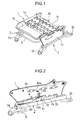
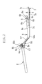
Japanese Patent Application Laid-Open No. 2004-51082 Figs. 1 to 5 , the conventional sliding-type automobile seat will be discussed in order to facilitate understanding of the present invention. As shown inFig. 1 , this automobile seat includes a seat cushion frame 1 for a seat cushion thereof. The seat cushion frame 1 comprises a pair of spaced apartside frame sections 1a, apan frame section 1b arranged and fixed between forward portions of theside frame sections 1a, and arear frame section 1c arranged and fixed between rearward portions of theside frame sections 1a. - The automobile seat can be slidingly moved forward and rearward in an automobile via a
slide rail mechanism 2. As shown inFig. 2 , theslide rail mechanism 2 comprisesupper rails 2a attached to lower portions of theside frame sections 1a (only oneside frame section 1a and only oneupper rail 2a are shown inFig. 2 ), and a pair of parallellower rails 2b mounted on a floor surface of the automobile viastand leg portions lower rail 2b is shown inFig. 2 ). Theupper rails 2a are slidably engaged with thelower rails 2b as will be fully discussed hereinafter, whereby the seat can be slidingly moved forward and rearward in the automobile. - As shown in
Fig. 3 , each of theupper rails 2a (only oneupper rail 2a is shown inFig. 3 ) comprises a pair ofmembers side frame section 1a of the automobile seat by asupport pin 40 and hang downward from theside frame section 1a. Each of thelower rails 2b (only onelower rail 2b is shown inFig. 3 ) has alongitudinal body 21 of a substantially U-shape in cross-section and is mounted on the floor surface of the automobile with an opening portion thereof facing upward. Thelower rail body 21 includesinward bent flanges lower rail body 21 in such a manner to allow a space to be produced between theinward bent flanges - Each of the
upper rail 2a is combined with a correspondinglower rail 2b by causing lowercurved portions 20a', 20b' of the substantially J-shaped members side frame section 1a to be inserted into the substantially U-shapedlower rail body 21 through the space between theinward bent flanges lower rail body 21, and causing tip end portions of the lowercurved portions 20a', 20b' to be arranged inside theinward bent flanges lower rail body 21. Moreover, between the lowercurved portions 20a', 20b' of the substantially J-shaped members upper rail body 21 and a bottom surface of thelower rail body 21, a plurality ofrollers 23 are disposed (only oneroller 23 is shown inFig. 3 ), whereby the seat can be smoothly slid along the lower rails. - The sliding-type automobile seat is provided with slide lock mechanisms for causing the seat to be locked at predetermined positions with respect to the
lower rails 2b. As shown inFig. 4 , the slide lock mechanisms includelock plates 4 arranged at side portions of theupper rails 2a (only oneupper rail 2a and only onelock plate 4 are shown inFig. 4 ). Anoperating lever 5 for releasing the seat from a locked condition is provided so as to be bridged between thelock plates 4. - Again referring to
Figs. 3 and 4 , each of thelock plates 4 extends along the side portions of the substantially J-shaped members upper rail 2a. Thelock plate 4 is pivotally supported, at the substantially middle portion of its longitudinal direction, to the side portions of the substantially J-shaped members upper rail 2a by thesupport pin 40, whereby thelock plate 4 is vertically swingable around thesupport pin 40. Moreover, thelock plate 4 is formed, at its region adjacent a rear end portion thereof, with anelongated hole 41 vertically extending. Aguide pin 42 projects from the side portion of theupper rail 2a and is inserted through theelongated hole 41 formed in thelock plate 4, so that the vertical swinging movement of thelock plate 4 is guided along theelongated hole 41. - The
lock plate 4 is urged by acoil spring 43 so as to be always pulled upward at the rear end portion thereof. More particularly, thecoil spring 43 is retained at one end portion thereof to aprotruding piece 43a provided at a correspondingside frame section 1a, and retained at the other end portion thereof to aprotruding piece 43b bent from an upper edge of thelock plate 4, whereby thecoil spring 43 is provided between theside frame section 1a and thelock plate 4. - Each of the slide lock mechanisms further includes first and second engaging means. The first engaging means comprises an
engaging piece 44 projecting laterally from a lower edge of acorresponding lock plate 4 and a plurality of receivingholes 45 formed in theengaging piece 44. The lowercurved portions 20a', 20b' of the substantially J-shaped members upper rail 2a are formed withslits 46. Theengaging piece 44 of thelock plate 4 projects so as to cross theinward bent flange 22a of thelower rail 2b through theslits 46. - The second engaging means includes a plurality of protruding
teeth 47 that are formed by making a lower portion of aninward bent flange 22a of a correspondinglower rail 2b into a concave/convex form. Theprotruding teeth 47 are releasably engaged with the receivingholes 45 formed in theengaging piece 44 of thelock plate 4. - The
operating lever 5 is formed in a substantially U-shape as viewed from above by causing a pipe material to be bent. Both end portions of the U-shapedoperating lever 5 are flatly crushed and welded to forward portions of thelock plates 4, whereby theoperating lever 5 is connected to thelock plates 4. As shown inFig. 1 , theoperating lever 5 is bridged between thelock plates 4 and arranged under the seat cushion frame 1 with a forward portion thereof projecting forward of the seat. - In the slide lock mechanisms, the
lock plates 4 are always urged upward at the rear end portions thereof by thecoil springs 43 and theengaging pieces 44 are releasably meshed at the receivingholes 45 thereof with the protrudingteeth 47 as shown inFig. 4 , whereby theupper rails 2a are locked with respect to thelower rails 2b so as to be unable to be slid relative to thelower rails 2b. On the other hand, when theoperating lever 5 is pulled up in such a direction that it approaches the seat cushion frame, namely, in such a direction as to be indicated inFig. 5 by an arrow, the rear end portions of thelock plates 4 are swung downward about thesupport pins 40 against the actions of thecoil springs 43, whereby the receivingholes 45 of thelock plates 4 are released from the engagement with the protrudingteeth 47 of thelower rails 2b, the engagement of theupper rails 2a with respect to thelower rails 2b is therefore released, and the seat is brought to a condition where it can be slidingly moved forward and rearward in the automobile. - In a case where the conventional automobile seat constructed as discussed above is assembled, it is necessary to cause the lock plates to be individually mounted to the upper rails. However, since the lock plates are previously welded to the both end portions of the substantially U-shaped operating lever, when such lock plates are individually mounted to the upper rails, mounting work of one of the lock plates to one of the upper rails will be interrupted by the other of the lock plates as well as the operating lever and a lot of time is taken for connecting of the operating lever to the lock plates and assembling the entire lock mechanisms.
- Moreover, in the automobile provided with the seat constructed as discussed above, when any baggage, luggage, etc. is put on the floor surface of the automobile while being carelessly contacted with the operating lever, there is a possibility that the operating lever and/or the baggage, luggage, etc. will be damaged or deformed and the operating lever can not be properly operated. In this condition, if the operating lever is forcedly operated, there is a possibility that the operating lever will cause the baggage, luggage, etc. to be damaged or deformed.
- The present invention has been made in view of the above-mentioned problems of the prior art automobile seat.
- It is therefore an object of the present invention to provide a sliding-type automobile seat which facilitates connecting of an operating lever to slide lock mechanisms of the sliding-type automobile seat.
- It is another object of the present invention to provide a sliding-type automobile seat which is simply constructed and in which even if any baggage, luggage, etc. is contacted with the operating lever of the automobile seat, the baggage, luggage, etc. and/or the operating lever of the automobile seat can be prevented from being damaged or deformed.
- In accordance with the present invention, there is provided a sliding-type automobile seat which comprises a seat cushion frame, a slide rail mechanism for allowing the seat to be slidingly moved, slide lock mechanisms for causing the seat to be releasably locked at predetermined positions, a substantially U-shaped operating lever for causing the seat to be released from a locked state, and connection mechanisms for causing both end portions of the substantially U-shaped operating lever to the slide lock mechanisms. The slide rail mechanism comprises a pair of parallel lower rails mounted on a floor surface of an automobile, and a pair of parallel upper rails attached to a lower portion of the seat cushion frame and slidably engaged with the pair of parallel lower rails. Each of the slide rock mechanisms comprises a lock member swingably mounted to a corresponding upper rail and urged upward at one end portion thereof by a spring, the lock member including first engaging means, and second engaging means provided at a corresponding lower rail. The first engaging means and the second engaging means are releasably engaged with each other, to thereby cause the seat to be locked at the predetermined positions. Each of the connection mechanisms comprises a connection member having means for stoppingly engaging the lock member. The means for stoppingly engaging the lock member is engaged with the lock member, whereby the operating lever is connected, via the connection mechanisms, to the slide rock mechanism by one-touch operation.
- The means for stoppingly engaging the lock member may comprise a lower joint mounted on the connection member, and an upper joint fixed on the lower joint and extending along the lower joint in such a manner to allow a predetermined space the upper joint and the lower joint. The lock member may comprise a receiving piece for receiving one end portion of the lower joint, a holding-down piece for holding down the lower joint in the space between the lower joint and the upper joint, and a leaf spring having a first spring portion for causing the one end portion of the lower joint to be pressed against the receiving piece to interposingly hold the one end portion of the lower joint therebetween, and a second spring portion for pushing up the upper joint in the space to cause the holding-down piece to be pressed against the lower joint.
- The upper joint may have a through-hole formed therein and the left spring may be provided with an engaging claw, the engaging claw being engaged with the through-hole.
- The substantially U-shaped operating lever may include extending portions linearly extending laterally from the both end portions thereof, and support pins fitted in the extending portions of the operating lever, each of the support pins being connected to a connection member of a corresponding connection mechanism, coil springs for causing the operating lever to be urged upward are mounted at coiled portions thereof around the support pins, first end portions of the coil springs being stoppingly engaged with end portions of the support pins and second end portions of the coil springs being stoppingly engaged with connection members of the connection mechanisms, and stopper members provided around the support pins for engaging the connection members from above.
-
-
Fig. 1 is a perspective view showing a seat cushion frame of a conventional sliding-type automobile seat; -
Fig. 2 is a perspective view showing only one of side frame sections of the seat cushion frame shown inFig. 1 ; -
Fig. 3 is a sectional view of a slide rail mechanism provided at the seat cushion frame shown inFig. 1 ; -
Fig. 4 is a sectional view of the slide rail mechanism, taken along a line A-A inFig. 3 ; -
Fig. 5 is a view showing a condition where the seat is released from a locked state; -
Fig. 6 is a plan view showing an operating lever which is employed in a sliding-type automobile seat according to the present invention and in which a central portion of the operating lever has been left out of the illustration; -
Fig. 7 is a view illustrating a condition where the operating lever shown inFig. 6 is connected to connection mechanisms; -
Fig. 8 is a view that fully shows connection between the operating lever and the connection mechanisms; -
Fig. 9 is an enlarged sectional view, taken along a line B-B inFig. 8 ; -
Fig. 10 is a view that shows a condition where the operating lever shown inFig. 6 is connected to slide lock mechanisms via the connection mechanisms; -
Fig. 11 is an enlarged view that fully shows the condition where the operating lever is connected to the slide lock members via the connection mechanisms; and -
Fig. 12 is an enlarged sectional view that is of assistance in explaining a condition where the connection mechanisms are connected to the operating lever. - Referring to
Figs. 6 to 12 , a sliding-type automobile seat according to an embodiment of the present invention will be discussed hereinafter. The sliding-type automobile seat according to the present invention is substantially similar to the conventional automobile seat shown inFigs. 1 to 5 except that a different operating lever 5', different slide lock mechanisms, and connection mechanisms for facilitating connecting of the operating lever 5' and the slide lock mechanisms are employed. Therefore, description of the respective components except the operating lever, the connection mechanisms and the slide lock mechanisms will not be repeated. - The slide lock mechanisms of the automobile seat according to the present invention comprises elongated lock members 4' (see
Fig. 10 showing only one lock member 4') that are different from thelock plates 4 of the conventional automobile seat, swingably mounted to the upper rails and provided with the first engagingmeans 44, 45 (seeFigs. 3 ), and the second engaging means 47 (seeFig. 3 ) provided at the lower rails. The first and second engaging means are releasably engaged with each other, whereby the seat is locked at predetermined positions. The operating lever 5' serves as means to release the engagement between the first engaging means and the second engaging means and is connected to the lock members 4' via longitudinal connection members 6 of the connection mechanisms (seeFigs. 7 to 10 showing only one connection member 6). - The operating lever 5' is formed in a predetermined shape by causing a pipe material to be bent. More particularly, as shown in
Fig. 6 , the operating lever 5' comprises a substantially U-shaped body having a central axial grip-portion 5a which is to be gripped by an occupant on the seat when the operating lever 5' is operated by the occupant, and left and rightaxial portions Annular flanges axial portions axial portions - The support pins 5c, 5c comprise inner
axial portions axial portions axial portions end portions axial portions protruding end portions protruding end portions -
Stoppers axial portions stoppers axial portions stoppers ring portions 55a fixedly mounted around the outeraxial portions portions 55b protruding laterally from upper edges of peripheries of thering portions 55a. - As shown in
Figs. 7 to 9 , the left and rightaxial portions 5b of the operating lever 5' are connected to forwardend portions 6a of the longitudinal connection members 6 via the support pins 5c (respective components in connection with only one of the connection mechanisms are shown inFigs. 7 to 9 ). The connection mechanisms includelower joints 7 provided onrearward end portions 6b of the longitudinal connection members 6 thereof and engagedly connected to the lock members 4' that are mounted to the upper rails, andupper joints 8 fixed onto thelower joints 7. Theupper joints 8 extend rearward in such a manner to allow spaces to be produced between thelower joints 7 and theupper joints 8 and are engagedly connected to the lock members 4'. - As shown in
Fig. 7 , the longitudinal connection members 6 are formed in substantially L-shapes and includeintermediate portions 6c extending between theforward end portions 6a and therearward end portions 6b so as to have slopes descending from theforward end portions 6a. The support pins 5c of the operating lever 5' are penetrated through theforward end portions 6a of the longitudinal connection members 6, whereby the U-shaped operating lever 5' is connected to the longitudinal connection members 6. Moreover, as shown inFig. 8 , each of the longitudinal connection members 6 is formed in a substantially U-shape in cross-section and includes a pair of spaced apart risingflanges flanges 6d of the connection members 6 which are located at theforward end portions 6a of the connection members 6, receivingrecesses 6e for engagingly receiving the protrudingportions 55b of thestoppers 55 of the operating lever 5' are formed so as to have widths larger than those of the protrudingportions 55b (widths measured in circumferential directions of thering portions 55a of the stoppers 55). - As shown in
Figs. 10 and11 , thelower joints 7 compriseforward end portions 7a fixedly welded onto inner surfaces of bottoms of the connection members 6,rearward end portions 7c located at positions higher than theforward end portions 7a, and longitudinalintermediate portions 7b extending between theforward end portions 7a and therearward end portions 7c. The longitudinalintermediate portions 7b extend slightly downward relative to therear end portions 6b of the connection members 6, further extend horizontally and still further extend upward to therearward end portions 7c. - The
upper joints 8 are formed in substantially U-shapes in cross-section and comprisesforward end portions 8a fixedly welded onto theforward end portions 7a of thelower joints 7,rear end portions 8c rising up, andintermediate portions 8b interconnecting theforward end portions 8a and therear end portions 8c, and extending from theforward end portions 8a along thelower joints 7 so as to be vertically spaced apart from thelower joints 7 at predetermined intervals G (Fig. 7 ). Moreover, theintermediate portions 8b are formed with elongated through-holes 8d of substantially rectangle-shapes at regions thereof which are adjacent therearward end portions 8c of theupper joints 8. - The elongated lock members 4' comprise longitudinal plate-shaped portions, spaced apart side portions protruding forward from forward ends of the longitudinal plate-shaped portions, receiving
pieces 48a provided at forward ends of the spaced apart side portions and bridged between lower regions of the spaced apart side portions, and holding-downpieces 48b provided at regions of the spaced apart side portions that are adjacent the longitudinal plate-shaped portions, the holding-downpieces 48b being bridged between the lower regions of the spaced apart side portions. When the connection mechanisms connected to the operating lever 5' are connected to the slide lock mechanisms, the receivingpieces 48a are adapted to engagingly receive therear end portions 7c of thelower joints 7 and the holding-down pieces are inserted in the intervals G between theintermediate portions 7b of thelower joints 7 and theupper joints 8 and hold down the longitudinalintermediate portions 7b of thelower joints 7. The receivingpieces 48a and the holding-downpieces 48b are formed into substantially U-shapes in cross-section. - Moreover,
elongated leaf springs 9 are attached to the lock members 4'. Theleaf springs 9 are arranged between the spaced apart side portions of the elongated lock members 4' and comprise bodies having substantially U-shaped in cross-section. The substantially U-shaped bodies comprisefirst spring portions 9a for pressing therearward end portions 7c of thelower joints 7 against the receivingpieces 48a of the lock members 4' and interposedly holding therearward end portions 7c of thelower joints 7 therebetween, andsecond spring portions 9b inserted in the intervals G between thelower joints 7 and theupper joints 8 for pushing theupper joints 8 upward to cause the holding downpieces 48b to be pressed against the longitudinalintermediate portions 7b of thelower joints 7. - The
first spring portions 9a and thesecond spring portions 9b are formed by bottom surfaces of the substantially U-shaped bodies of the leaf springs 9. Engagingclaws 9c of substantially triangle-shapes are provided on thesecond spring portions 9b. Moreover, spring-supportingmembers 49a are arranged between the spaced apart side portions of the lock members 4' and swingably supported to the lock members 4' via support pins 49b. Theleaf springs 9 are also swingably supported to the lock members 4' via the support pins 49b. Moreover, elongated return springs 49 are attached at one end portions thereof to the spring-supportingmembers 49a bypins 49c. Therefore, the return springs 49 are also swingable together with the spring-supportingmembers 49a. The return springs 49 serve to urge the connection members 6 in such a direction to cause the connection members 6 to be locked with respect to the lock members 4', when the connection members 6 connected to the U-shaped operating lever 5' are connected to the lock members 4' for assembling. Though not shown, the lock members 4' are attached to the upper rails by causing thepins 49c to be penetrated through the upper rails and then causing thepins 49c to be riveted over surfaces of the upper rails. The lock members 4' are urged upward by the coil springs (not shown) in the same manner as thelock plates 4 of the conventional seat are done. Moreover, though not shown, the lock members 4' are provided at the longitudinal plate-shaped portions thereof with the engaging pieces 44 (Fig. 3 ) having the engaging holes 45 (seeFig. 3 ) with which the protruding teeth 47 (seeFig. 3 ) of the lower rails are engaged, like thelock plates 4 of the conventional seat. - The lock members 4' are individually mounted to the upper rails and the operating lever 5' are then connected via the connection mechanisms to the lock members 4', so that the connecting of the operating lever 5' to the slide lock mechanisms is carried out by one-touch operation with utilizing the connection mechanisms constructed as discussed above.
- The connecting of the operating lever 5' to the slide lock mechanisms through the connection mechanisms connected to the operating lever 5' is carried out as follows. As shown in
Figs. 10 and11 , the connection members 6 connected to the left and right axial portions of the operating lever 5' are engaged at therearward end portions 7c of thelower joints 7 thereof with the receivingpieces 48a of the lock members 4', and the holding-downpieces 48b of the lock members 4' are inserted into the gaps G between the longitudinalintermediate portions 7b of thelower joints 7 and theupper joints 8 while being applied onto the longitudinalintermediate portions 7b of thelower joints 7 and engaged at the through-holes 8d of theupper joints 8 with the engagingclaws 9c of the leaf springs 9. At this time, therearward end portions 7c of thelower joints 7 are pressed against the receivingpieces 48a of the lock members 4' by thefirst spring portions 9a of theleaf springs 9, whereby therearward end portions 7c of thelower joints 7 are interposedly held between thefirst spring portions 9a of theleaf springs 9 and the receivingpieces 48a. Moreover, theupper joints 8 are pushed up in the gap G between theupper joints 8 and thelower joints 7 by thesecond spring portions 9b of theleaf springs 9, to thereby cause the holding-downpieces 48b of the lock members 4' to be pressed against the longitudinalintermediate portions 7b of thelower joints 7. Thus, the connecting of the operating lever 5' to the slide lock mechanisms through the connection mechanisms can be easily performed by one-touch operation. Therefore, it is possible to facilitate speedy assembling work of the entire lock mechanisms. - In addition to the urging by the
leaf springs 9, the through-holes 8d formed in the regions of theupper joints 8 which are adjacent therearward end portions 8c of theupper joints 8, and the engagingclaws 9c provided on thesecond spring portions 9b of theleaf springs 9 are engaged with each other, whereby the connection members 6 connected to the left and right axial portions of the operating lever 5' can be securely connected to the lock members 4' so as not to be removed from the lock members 4'. - The operating lever 5' is connected at the left and right axial portions thereof to the forward ends 6a of the connection members 6 by the support pins 5c with protruding
portions 55b of thestoppers 55 thereof being received in the receiving recesses 6e of the connection members 6. The entire operating lever 5' is urged upward by coil springs 56. Thus, the operating lever 5' is adapted to be pivotable downward of the connection members 6 and able to be pulled up in order that the lock members 4' are released from locked states. - As shown in
Figs. 8, 9 and12 , the coil springs 56 are stretched between the support pins 5c and the connection members 6 by causingcoil portions 56a of the coil springs 56 to be mounted around the outeraxial portions 51 of the support pins 5c penetrating the risingflanges first end portions 56b of the coil springs 56 to be engagedly fitted in theslits 54 of the support pins 5c, and causing thesecond end portions 56c of the coil springs 56 to be engagedly fitted inspring receiver sleeves 6f that are provided on the inner surfaces of the bottoms of the connection members 6 (only one of the connection members 6 and only one of the support pins 5c of the operating lever 5' are shown inFigs. 8, 9 and12 ). Incidentally, the bush nuts or E-rings 57 are mounted on the protrudingaxial portions 52 of the support pins 5c, whereby the support pins 5c are prevented from being disconnected from the connection members 6. - The entire operating lever 5' is adapted to be able to be pivoted downward against the actions of the coil springs 56 until the protruding
portions 55b of thestoppers 55 are abutted against edges of the receiving recesses 6e of the connection members 6 (seeFig. 10 ), so that even if any baggage, luggage, etc. is contacted with the operating lever 5' from above, the baggage, luggage, etc and/or the operating lever 5' can be prevented from being damaged or deformed. Moreover, it is possible to easily pull the operating lever 5' up in order that the lock members 4' are released from the engagement with the lower rails. - The terms and expressions which have been employed herein are used as terms of description, not of limitation. There is no intention in the use of such terms and expressions of excluding any equivalents of the features described or any portions thereof. It is recognized, however, that various modifications are possible within the scope of the invention claimed.
Claims (4)
- A sliding-type automobile seat comprising:a seat cushion frame;a slide rail mechanism for allowing said seat to be slidingly moved;slide lock mechanisms for causing said seat to be releasably locked at predetermined positions;a substantially U-shaped operating lever for causing said seat to be released from a locked state; andconnection mechanisms for causing both end portions of said substantially U-shaped operating lever to said slide lock mechanisms;said slide rail mechanism comprising a pair of parallel lower rails mounted on a floor surface of an automobile, and a pair of parallel upper rails attached to a lower portion of said seat cushion frame and slidably engaged with the pair of parallel lower rails;each of said slide rock mechanisms comprising a lock member swingably mounted to a corresponding upper rail and urged upward at one end portion thereof by a spring, said lock member including first engaging means, and second engaging means provided at a corresponding lower rail;said first engaging means and said second engaging means being adapted to be releasably engaged with each other, to thereby cause said seat to be locked at the predetermined positions;each of said connection mechanisms comprising a connection member having means for stoppingly engaging said lock member; andsaid means for stoppingly engaging said lock member being engaged with said lock member, whereby said operating lever is connected, via said connection mechanisms, to said slide rock mechanism by one-touch operation.
- A sliding-type automobile seat according to claim 1, wherein said means for stoppingly engaging said lock member comprises a lower joint mounted on said connection member, and an upper joint fixed on said lower joint and extending along said lower joint in such a manner to allow a predetermined space said upper joint and said lower joint;
said lock member comprises a receiving piece for receiving one end portion of said lower joint, a holding-down piece for holding down said lower joint in said space between said lower joint and said upper joint, and a leaf spring having a first spring portion for causing the one end portion of said lower joint to be pressed against said receiving piece to interposingly hold the one end portion of said lower joint therebetween, and a second spring portion for pushing up said upper joint in the space to cause said holding-down piece to be pressed against said lower joint; and
said operating lever is connected via said connection member to said lock member after the lock member is attached to the corresponding upper rail. - A sliding-type automobile seat according to claim 2, wherein said upper joint has a through-hole formed therein and said left spring is provided with an engaging claw, said engaging claw being engaged with said through-hole.
- A sliding-type automobile seat according to any one of claims 1 to 3, wherein said substantially U-shaped operating lever includes extending portions linearly extending laterally from the both end portions thereof, and support pins fitted in said extending portions of the operating lever, each of said support pins being connected to a connection member of a corresponding connection mechanism, coil springs for causing said operating lever to be urged upward are mounted at coiled portions thereof around said support pins, first end portions of said coil springs being stoppingly engaged with end portions of said support pins and second end portions of said coil springs being stoppingly engaged with connection members of said connection mechanisms, and stopper members provided around said support pins for engaging said connection members from above.
Applications Claiming Priority (3)
| Application Number | Priority Date | Filing Date | Title |
|---|---|---|---|
| JP2005140227A JP4899208B2 (en) | 2005-05-12 | 2005-05-12 | Sliding car seat |
| JP2005140216A JP4771116B2 (en) | 2005-05-12 | 2005-05-12 | Sliding car seat |
| PCT/JP2006/309984 WO2006121216A1 (en) | 2005-05-12 | 2006-05-12 | Sliding-type automobile seat |
Publications (2)
| Publication Number | Publication Date |
|---|---|
| EP1914109A1 true EP1914109A1 (en) | 2008-04-23 |
| EP1914109A4 EP1914109A4 (en) | 2013-01-30 |
Family
ID=37396699
Family Applications (1)
| Application Number | Title | Priority Date | Filing Date |
|---|---|---|---|
| EP06746644A Withdrawn EP1914109A4 (en) | 2005-05-12 | 2006-05-12 | Sliding-type automobile seat |
Country Status (3)
| Country | Link |
|---|---|
| US (1) | US7798462B2 (en) |
| EP (1) | EP1914109A4 (en) |
| WO (1) | WO2006121216A1 (en) |
Families Citing this family (11)
| Publication number | Priority date | Publication date | Assignee | Title |
|---|---|---|---|---|
| FR2899523B1 (en) * | 2006-04-10 | 2008-06-27 | Faurecia Sieges Automobile | SYSTEM COMPRISING A MOTOR VEHICLE SEAT SLIDE AND A BODY FOR FIXING THE SAME, AND METHOD OF MANUFACTURING THE SAME |
| US8006949B2 (en) * | 2006-08-07 | 2011-08-30 | Aisin Seiki Kabushiki Kaisha | Seat slide device for vehicle |
| US20120001049A1 (en) * | 2008-04-18 | 2012-01-05 | Johnson Controls Technology Company | Latch mechanism |
| DE102008061109B4 (en) * | 2008-12-09 | 2019-05-09 | GM Global Technology Operations LLC (n. d. Ges. d. Staates Delaware) | Operating lever for a Längsverstellvorrichtung a motor vehicle seat |
| US8038115B2 (en) * | 2009-02-12 | 2011-10-18 | Lear Corporation | Sliding seat track having a secondary retaining structure |
| JP5616116B2 (en) * | 2010-04-28 | 2014-10-29 | シロキ工業株式会社 | Slide rail device for vehicle |
| JP5214711B2 (en) | 2010-11-25 | 2013-06-19 | 岐阜車体工業株式会社 | Lock mechanism in seat track slide device |
| JP5214712B2 (en) | 2010-11-25 | 2013-06-19 | 岐阜車体工業株式会社 | Lock mechanism in seat track slide device |
| DE102012009235B4 (en) * | 2012-05-09 | 2021-01-14 | Brose Fahrzeugteile SE & Co. Kommanditgesellschaft, Coburg | Seat rail for a motor vehicle seat |
| DE102014211993B4 (en) * | 2014-06-23 | 2019-09-05 | Lear Corporation | Seat rail assembly with load bearing structures and vehicle seat assembly |
| JP7104971B2 (en) * | 2018-08-08 | 2022-07-22 | デルタ工業株式会社 | slide device |
Family Cites Families (16)
| Publication number | Priority date | Publication date | Assignee | Title |
|---|---|---|---|---|
| DE4102312C2 (en) * | 1991-01-26 | 1994-08-25 | Keiper Recaro Gmbh Co | Seat rail for vehicle seats, in particular for motor vehicle seats |
| JP3400613B2 (en) * | 1995-06-28 | 2003-04-28 | アイシン精機株式会社 | Vehicle seat slide device |
| US5918846A (en) * | 1996-12-11 | 1999-07-06 | Meritor Automotive Canada, Inc. | Seat track with continuous engagement and memory easy entry mechanism |
| JP3295627B2 (en) * | 1997-10-21 | 2002-06-24 | 富士機工株式会社 | Seat slide device |
| JP4060466B2 (en) * | 1998-11-06 | 2008-03-12 | テイ・エス テック株式会社 | Operating mechanism |
| FR2797234B1 (en) * | 1999-08-02 | 2001-10-05 | Faure Bertrand Equipements Sa | SLIDE FOR VEHICLE SEAT AND SEAT COMPRISING SUCH A SLIDE |
| US6354553B1 (en) * | 2000-03-01 | 2002-03-12 | Dura Global Technologies, Inc. | Seat track assembly with positive lock mechanism |
| JP2002120605A (en) * | 2000-10-18 | 2002-04-23 | Delta Kogyo Co Ltd | Slider for seat |
| US20030006355A1 (en) * | 2001-07-09 | 2003-01-09 | Horsfield Keith C. | Seat track assembly with locking mechanism |
| BR0205816B1 (en) * | 2001-08-01 | 2011-05-17 | system with a sliding type folding seat and a vehicle body floor. | |
| KR100442746B1 (en) * | 2001-11-08 | 2004-08-02 | 주식회사다스 | Locking system of seat rail for vehicle |
| JP4247405B2 (en) * | 2002-05-31 | 2009-04-02 | テイ・エス テック株式会社 | Sliding car seat |
| US6767063B1 (en) * | 2003-01-20 | 2004-07-27 | Lear Corporation | Automotive easy-entry assembly |
| FR2853597B1 (en) * | 2003-04-08 | 2006-04-28 | Faurecia Sieges Automobile | SLIDER FOR SEAT OF MOTOR VEHICLE |
| JP2005088751A (en) * | 2003-09-17 | 2005-04-07 | Delta Kogyo Co Ltd | Slide adjuster for vehicle |
| US7293752B2 (en) * | 2004-10-28 | 2007-11-13 | Lear Corporation | Positive engagement latch for a vehicle seat |
-
2006
- 2006-05-12 WO PCT/JP2006/309984 patent/WO2006121216A1/en not_active Ceased
- 2006-05-12 US US11/913,787 patent/US7798462B2/en not_active Expired - Fee Related
- 2006-05-12 EP EP06746644A patent/EP1914109A4/en not_active Withdrawn
Also Published As
| Publication number | Publication date |
|---|---|
| EP1914109A4 (en) | 2013-01-30 |
| WO2006121216A1 (en) | 2006-11-16 |
| US20090032670A1 (en) | 2009-02-05 |
| US7798462B2 (en) | 2010-09-21 |
Similar Documents
| Publication | Publication Date | Title |
|---|---|---|
| JP5239332B2 (en) | Vehicle seat slide device | |
| US9283870B2 (en) | Seat sliding device for vehicle | |
| US7798462B2 (en) | Sliding-type automobile seat | |
| EP1658193B1 (en) | Locking mechanism for seat track assembly | |
| US7243974B2 (en) | Locking devices for vehicle seats | |
| US10308146B1 (en) | Track release mechanism for a seating assembly | |
| CN102112339B (en) | Seat Sliders for Vehicles | |
| EP1697161B1 (en) | Vehicle seat assembly and floor rail for lateral seat shuttling | |
| US4109973A (en) | Vehicle seat slide adjuster including integrally formed pawl and pawl lever | |
| DE102008063617A1 (en) | vehicle seat | |
| DE102009003814A1 (en) | Cable connectors | |
| DE102006035465B4 (en) | Vehicle boarding device | |
| US20050269854A1 (en) | Vehicle seat latch assembly having a pivoting anti-chuck hook for engaging a floor-mounted striker plate | |
| CN113286724B (en) | Latching system for vehicle seats | |
| US11124091B2 (en) | Seat release mechanism | |
| JP2003252086A (en) | Seat slide device | |
| US20040017091A1 (en) | Dismountable seat for an automobile capable of being automatically tumbled and mounted in a face-to-face manner | |
| JP5505008B2 (en) | Vehicle sliding device | |
| JPH08508454A (en) | Car seat adjuster | |
| EP1369295A1 (en) | A chassis suitable for attaching an infant vehicle seat to a vehicle seat, such an assembly and an infant vehicle seat | |
| CN101175652B (en) | Sliding car seat | |
| JP2011079370A (en) | Lock unit mounting structure of seat slide lock device for vehicle | |
| JP2008024110A (en) | Automotive seat slide device | |
| JP2007176220A (en) | Vehicle seat slide device | |
| JP4899208B2 (en) | Sliding car seat |
Legal Events
| Date | Code | Title | Description |
|---|---|---|---|
| PUAI | Public reference made under article 153(3) epc to a published international application that has entered the european phase |
Free format text: ORIGINAL CODE: 0009012 |
|
| 17P | Request for examination filed |
Effective date: 20071211 |
|
| AK | Designated contracting states |
Kind code of ref document: A1 Designated state(s): DE FR GB |
|
| DAX | Request for extension of the european patent (deleted) | ||
| RBV | Designated contracting states (corrected) |
Designated state(s): DE FR GB |
|
| A4 | Supplementary search report drawn up and despatched |
Effective date: 20130107 |
|
| RIC1 | Information provided on ipc code assigned before grant |
Ipc: B60N 2/08 20060101AFI20121221BHEP |
|
| 17Q | First examination report despatched |
Effective date: 20140218 |
|
| GRAP | Despatch of communication of intention to grant a patent |
Free format text: ORIGINAL CODE: EPIDOSNIGR1 |
|
| INTG | Intention to grant announced |
Effective date: 20151208 |
|
| STAA | Information on the status of an ep patent application or granted ep patent |
Free format text: STATUS: THE APPLICATION IS DEEMED TO BE WITHDRAWN |
|
| 18D | Application deemed to be withdrawn |
Effective date: 20160419 |