EP1913504B1 - Method and apparatus for generating multiple studies - Google Patents
Method and apparatus for generating multiple studies Download PDFInfo
- Publication number
- EP1913504B1 EP1913504B1 EP06780228A EP06780228A EP1913504B1 EP 1913504 B1 EP1913504 B1 EP 1913504B1 EP 06780228 A EP06780228 A EP 06780228A EP 06780228 A EP06780228 A EP 06780228A EP 1913504 B1 EP1913504 B1 EP 1913504B1
- Authority
- EP
- European Patent Office
- Prior art keywords
- scan
- patient
- protocol
- study
- anatomy
- Prior art date
- Legal status (The legal status is an assumption and is not a legal conclusion. Google has not performed a legal analysis and makes no representation as to the accuracy of the status listed.)
- Active
Links
Images

Classifications
-
- A—HUMAN NECESSITIES
- A61—MEDICAL OR VETERINARY SCIENCE; HYGIENE
- A61B—DIAGNOSIS; SURGERY; IDENTIFICATION
- A61B6/00—Apparatus or devices for radiation diagnosis; Apparatus or devices for radiation diagnosis combined with radiation therapy equipment
- A61B6/02—Arrangements for diagnosis sequentially in different planes; Stereoscopic radiation diagnosis
- A61B6/03—Computed tomography [CT]
- A61B6/032—Transmission computed tomography [CT]
-
- A—HUMAN NECESSITIES
- A61—MEDICAL OR VETERINARY SCIENCE; HYGIENE
- A61B—DIAGNOSIS; SURGERY; IDENTIFICATION
- A61B6/00—Apparatus or devices for radiation diagnosis; Apparatus or devices for radiation diagnosis combined with radiation therapy equipment
- A61B6/04—Positioning of patients; Tiltable beds or the like
- A61B6/0487—Motor-assisted positioning
-
- A—HUMAN NECESSITIES
- A61—MEDICAL OR VETERINARY SCIENCE; HYGIENE
- A61B—DIAGNOSIS; SURGERY; IDENTIFICATION
- A61B6/00—Apparatus or devices for radiation diagnosis; Apparatus or devices for radiation diagnosis combined with radiation therapy equipment
- A61B6/08—Auxiliary means for directing the radiation beam to a particular spot, e.g. using light beams
-
- A—HUMAN NECESSITIES
- A61—MEDICAL OR VETERINARY SCIENCE; HYGIENE
- A61B—DIAGNOSIS; SURGERY; IDENTIFICATION
- A61B6/00—Apparatus or devices for radiation diagnosis; Apparatus or devices for radiation diagnosis combined with radiation therapy equipment
- A61B6/52—Devices using data or image processing specially adapted for radiation diagnosis
- A61B6/5211—Devices using data or image processing specially adapted for radiation diagnosis involving processing of medical diagnostic data
- A61B6/5229—Devices using data or image processing specially adapted for radiation diagnosis involving processing of medical diagnostic data combining image data of a patient, e.g. combining a functional image with an anatomical image
- A61B6/5235—Devices using data or image processing specially adapted for radiation diagnosis involving processing of medical diagnostic data combining image data of a patient, e.g. combining a functional image with an anatomical image combining images from the same or different ionising radiation imaging techniques, e.g. PET and CT
-
- A—HUMAN NECESSITIES
- A61—MEDICAL OR VETERINARY SCIENCE; HYGIENE
- A61B—DIAGNOSIS; SURGERY; IDENTIFICATION
- A61B6/00—Apparatus or devices for radiation diagnosis; Apparatus or devices for radiation diagnosis combined with radiation therapy equipment
- A61B6/54—Control of apparatus or devices for radiation diagnosis
- A61B6/542—Control of apparatus or devices for radiation diagnosis involving control of exposure
-
- G—PHYSICS
- G16—INFORMATION AND COMMUNICATION TECHNOLOGY [ICT] SPECIALLY ADAPTED FOR SPECIFIC APPLICATION FIELDS
- G16H—HEALTHCARE INFORMATICS, i.e. INFORMATION AND COMMUNICATION TECHNOLOGY [ICT] SPECIALLY ADAPTED FOR THE HANDLING OR PROCESSING OF MEDICAL OR HEALTHCARE DATA
- G16H10/00—ICT specially adapted for the handling or processing of patient-related medical or healthcare data
- G16H10/20—ICT specially adapted for the handling or processing of patient-related medical or healthcare data for electronic clinical trials or questionnaires
-
- G—PHYSICS
- G16—INFORMATION AND COMMUNICATION TECHNOLOGY [ICT] SPECIALLY ADAPTED FOR SPECIFIC APPLICATION FIELDS
- G16H—HEALTHCARE INFORMATICS, i.e. INFORMATION AND COMMUNICATION TECHNOLOGY [ICT] SPECIALLY ADAPTED FOR THE HANDLING OR PROCESSING OF MEDICAL OR HEALTHCARE DATA
- G16H30/00—ICT specially adapted for the handling or processing of medical images
- G16H30/20—ICT specially adapted for the handling or processing of medical images for handling medical images, e.g. DICOM, HL7 or PACS
Definitions
- the present invention relates to the field of medical imaging, and particularly to techniques for generating multiple studies or series from data obtained during a scanning procedure. It will be appreciated, however, that the invention finds applicability to other fields such as the imaging of animals, non-medical imaging, and industrial inspection.
- Computed tomography (CT) and other imaging scanners are well suited to obtaining information indicative of the internal characteristics of an object under examination, for example the internal anatomy of a human patient.
- CT Computed tomography
- these devices have been increasingly able to scan relatively larger areas of a patient in a given period of time and to generate ever increasing numbers of images and other information.
- advances in technology have also allowed greater flexibility in selecting the type and formats of the images to be generated and displayed.
- Scanners are commonly used to generate image data indicative of a region of the patient's anatomy, for example of the head, neck, chest, abdomen, or pelvis. In some cases, it is necessary to obtain information about multiple regions of the patient's anatomy. In that case, the images and other information regarding the various regions may be used by different persons or for different purposes, some or all of which may have different needs.
- Each region of the patient's anatomy can be scanned in a separate scanning procedure. Doing so provides flexibility in defining scanning and imaging parameters and storing and communicating the results of the scan, and also allows for relatively faster processing of only the region of interest. At the same time, however, conducting multiple scanning procedures on a particular patient can have various drawbacks, such as being inconvenient to the patient and relatively time consuming.
- Multiple regions of a patient's anatomy may also be scanned in a single scanning procedure. Doing so can be relatively more convenient for the patient and also more time efficient. At the same time, however, scanning multiple regions of the patient in a single scan has heretofore offered relatively little flexibility in defining scanning and imaging parameters, storing and communicating the scan results, and has required the relatively cumbersome processing of large data sets.
- EP 0 983 747 A1 discloses a cardiac gated spiral computed tomography (CT) scanner and imaging technique.
- Patient parameters such as breath-hold time or mean heart rate are determined.
- a pilot scan roughly images the patient's anatomy so that a range of coverage which contains a desired region of interest is readily discernable.
- a scan protocol is selected from a look up table.
- An imaging spiral CT scan is run in accordance with the selected protocol, and electrocardiogram (ECG) data are acquired at the same time.
- ECG electrocardiogram
- CT Fluoro computed tomography fluoroscopic
- a computer-implemented method is provided as defined in claim 1.
- an apparatus is proposed as defined in claim 22.
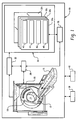
- a computed tomography (CT) scanner 10 includes a rotating gantry 18 which rotates about the z-axis.
- the gantry 18 supports an x-ray source 12 such as an x-ray tube.
- the gantry 18 also supports an x-ray sensitive detector 20 which subtends an angular arc on the opposite side of an examination region 14. X-rays produced by the x-ray source 12 traverse the examination region 14 and are detected by the detector 20.
- the detector 20 is a multi-slice detector which includes more than one row of detectors extending in the z-direction.
- Flat panel or other detector 20 configurations may also be implemented.
- the x-ray source 12 generates a generally fan, wedge, or cone shaped radiation beam.
- a so-called fourth generation scanner configuration in which the detector 20 spans an arc of 360 degrees and remains stationary while the x-ray source 12 rotates, may also be implemented.
- a patient support 16 such as a couch supports the patient in the examination region 14.
- the patient support 16 is preferably movable in the z-direction.
- a controller 28 coordinates the various scan parameters as necessary to carry out a desired scan protocol.
- movement of the support 16 and the gantry 18 are coordinated along with such that the x-ray source 12 and the detectors 20 traverse a generally helical path with respect to the patient.
- the movement of the support 16 and the gantry are coordinated such that the x-ray source 12 and the detectors traverse a generally linear path with respect to the patient, for example to provide an anterior-posterior or a lateral view of the patient.
- Data collected by the detector 20 are processed by a reconstructor 20 to generate volumetric data indicative of the interior anatomy of the patient.
- the images are stored in a suitable memory 30 such as a computer disk, other volatile or non-volatile memory or other memory storage device.
- the memory 30 is organized to store data indicative of a number of image series or studies 32a, 32b, 32c ... 32n.
- a unique identifier such as a study or accession number 42, patient information 44, and localizer 46 and diagnostic 48 images.
- the data associated with each series need not be in separate memory locations. Rather, the data may be arranged in suitable data structures and accessed using associated pointers, linked lists, or the like.
- Images and other information generated from the data obtained by the scanner are further manipulated by one or more imaging computers or workstations 36, which may also be used as the scanner console.
- the imaging computers or workstations 36 typically include an operator interface having an output device such as a human readable display and/or film printer and an input device such as a keyboard and/or mouse.
- the operator may view and manipulate images, select desired scan protocols, initiate or terminate scans, and otherwise interact with the scanner 10.
- the scanner 10 may also be in operative communication with a computer information system such as one or both of a hospital information system/radiology information system (HIS/RIS) 38 or picture archiving and communication system (PACS) system 40, over a HL-7, DICOM or other suitable interface.
- a computer information system such as one or both of a hospital information system/radiology information system (HIS/RIS) 38 or picture archiving and communication system (PACS) system 40, over a HL-7, DICOM or other suitable interface.
- HIS/RIS hospital information system/radiology information system
- PES picture archiving and communication system
- imaging requests are transferred from the computer information system such as the hospital HIS/RIS system 38 and received by the CT scanner 10.
- the imaging requests may include requests for separate scans that may be advantageously acquired in a single scan or requests to scan multiple regions for which there may be different informational requirements, for example requests covering one or more regions of the body such as the head, neck, chest, abdomen, or pelvis.
- imaging requests may be entered manually by the operator through the operator interface or otherwise.
- the CT scanner combines multiple procedure requests from the HIS/RIS system into one scan automatically based on internal rules and predefined protocols.
- these rules my combine requests for separate study conveying the chest, abdomen, and pelvis into a single scan, with each study being generated according to a predefined study protocol.
- the operator can combine the requests manually.
- Another method may include a predefined request from the HIS/RIS system to be interpreted as a single scan that has to be split into multiple studies or series by the scanner (either automatically or manually).
- a volumetric localizer scan of the patient is obtained.
- the localizer scan is preferably a relatively low dose or relatively fast, high pitch helical scan of the patient which provides information of a quality sufficient for localization purposes but which may not be optimal for diagnostic purposes.
- the reconstruction protocol is preferably selected to provide a relatively faster reconstruction time.
- the axial extent of the localizer scan corresponds approximately to the axial extent of the requested procedures.
- the localizer scan may be a surview scan.
- information from the localizer scan is used to identify the relevant regions of the patient's anatomy.
- the regions correspond to the regions of the requested procedures.
- a diagnostic quality CT scan which includes the relevant regions of the patient's anatomy is planned, and the desired studies are defined.
- the identified anatomical regions are used to establish a region of interest for each of two or more studies.
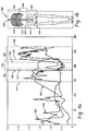
- the location of region of interest for three studies - a first study 602 in which the region of interest includes the patient's chest, a second study 604 in which the region of interest includes the patient's abdomen, and a third study 606 in which the region of interest includes the patient's pelvis — is depicted.
- the region of interest of the first study 602 overlaps with the region of interest of the second study 604, which in turn overlaps with the region of interest of the third study 606.
- portions of the patient's anatomy may be included in more than one study, with images or other information being generated according to the protocol corresponding to each study.
- an overview image 600 such as a maximum intensity projection (MIP) anterior posterior view or the patient's interior anatomy is generated from the localizer data and displayed on the operator interface, with the regions of interest 602, 604, 606 of the respective studies indicated on the overview image 600.
- MIP maximum intensity projection
- other views such as lateral views, volume visualized views, and the like, may also be displayed.
- the user may be afforded an opportunity to review and alter the region of interest definitions using the operator interface. Alternately, the definition of the regions of interest may proceed automatically without input from the operator.
- the region of interest for the various studies can also be described in other ways.
- the regions of interest can be described numerically with reference to the distance from a location on the patient support 16, a location on the patient's anatomy, a coordinate in image space, the slice number, or the like.
- each study it is sometimes desirable to establish different study protocols for one or all of the studies 602, 604, 606.
- a unique reconstruction protocol in which different values are established for one or more parameters related to image reconstruction (such as reconstruction filters, slice thicknesses, fields of view, or matrix sizes).
- parameters related to image reconstruction such as reconstruction filters, slice thicknesses, fields of view, or matrix sizes.
- each study it may be desirable for each study to have its own display protocol in which the format and other characteristics of the resulting images (such as axial, coronal, sagittal, multiplanar reformatted (MPR), MIP, or three dimensional rendered images, rendering parameters, coloration, or other information) are different.
- MPR multiplanar reformatted
- MIP multiplanar reformatted
- each study may be desirable for each study to have a different scan protocol in which different values are established for one or more parameters relating to the scanning operation (such as x-ray source 12 voltage or current, scan pitch, or collimation settings, in the case of a CT scanner).
- parameters relating to the scanning operation such as x-ray source 12 voltage or current, scan pitch, or collimation settings, in the case of a CT scanner.
- a default protocol is established for each study based on the region of interest of the study, the person requesting it, or other relevant characteristic.
- the protocols used to generate images of the head, neck, and chest or requested by a different physician or physician group may have different default values.
- some or all of the protocol information is entered by the operator.
- the imaging request received from the computer information system would be used to establish the some or all of the protocols parameter values.
- Other or different parameters, or differing combinations of them, can also be implemented depending on the type or characteristics of a particular scanner or the requirements of a particular application.
- a diagnostic CT scan covering the desired regions of the patient's anatomy is obtained.
- the axial extent of the scan would include the patient's chest, abdomen, and pelvis.
- the scan need not be continuous over the patient's anatomy. In cases where there are gaps between the studies or the requested procedures, there may be corresponding gaps in the regions covered by the scan.
- information from the diagnostic scan is used to generate the diagnostic image or images corresponding to each study, based on the study protocol established for each study.
- the information associated with each study is stored in memory 30.
- a unique identifier such an accession number 42, together with the relevant patient information 44, localizer image(s) 46, and diagnostic image(s) 48 are associated with each study 32a, 32b, 32c ... 32n.
- the studies are sent to a computer information system such as the PACS system 40 and a HIS/RIS or computer information system is notified that the studies corresponding to the requested procedures have been generated.
- imaging requests are transferred from a computer information system such as the hospital HIS/RIS system 26 and received by the CT scanner 10. Alternately, such the requests may be entered manually by the operator through the operator interface or otherwise.
- a localizer scan of the patient is obtained and data reconstructed.
- the localizer scan is preferably a relatively low dose surview scan providing a two dimensional anterior-posterior and/or lateral view of the patient.
- the localizer scan provides information of a quality sufficient for localization purposes but which may not be optimal for diagnostic purposes.
- the axial extent of the localizer scan corresponds approximately to the axial extent of the requested procedures.
- the localizer scan may be a low dose helical scan of the patient which provides volumetric information about the patient's anatomy.
- the operator uses the CT information from the localizer scan to establish the scan bounds for a diagnostic quality scan (e.g., the scan staring location and end location, as well as the scan field of view) which encompasses the relevant regions of interest.
- a diagnostic quality scan e.g., the scan staring location and end location, as well as the scan field of view
- a diagnostic quality CT scan which includes the relevant regions of the patient's anatomy is planned.
- an overview image 500 such as a maximum intensity projection (MIP) anterior posterior view or the patient's interior anatomy is generated from the localizer data and displayed on the operator interface, with the regions of interest 502 to be covered by the scan indicated on the overview image 500.
- the region 502 includes the patient's head and neck.
- the scan may cover more than one non-contiguous region.
- other views such as lateral views, volume visualized views, and the like, may also be displayed. The user may be afforded an opportunity to review and alter the axial extent of the scan using the operator interface. Alternately, the scan extent may be established automatically without operator review or feedback.
- the region to be covered by the scan may also be depicted in other ways.
- the locations can be depicted numerically with reference to the distance from a location on the patient support 16, a location on the patient's anatomy, the slice number, or the like.
- a scan protocol is also established for the scan.
- a diagnostic CT scan covering the desired region of the patient's anatomy is obtained at 308.
- the axial extent of the scan would include the patient's head and neck. Again, however, the scan need not be continuous over the patient's anatomy. In cases where there are gaps between relevant regions, there may be corresponding gaps in the data collected by the scan.
- the data from the scan is reconstructed to create volumetric data indicative of the patient's interior anatomy, preferably using a reconstruction protocol selected to provide a relatively faster reconstruction time. This reconstruction provides information of a quality sufficient for localization purposes but which may not be optimal for diagnostic purposes.
- information from the CT scan obtained at step 308 is analyzed to identify the relevant regions of the patient's anatomy.
- the relevant regions may also be identified based on the images generated from the volumetric data as they evolve during the course of an ongoing reconstruction.
- the regions of the anatomy identified in step 308 are used to defme multiple studies or series as generally described above in connection with step 206.
- studies similar to those defined in the example of Figure 4 , or other desired studies, could also be defined.
- information from the diagnostic scan is used to generate one or more diagnostic images corresponding to each study, based on the study protocol established for each study.
- each study may have different parameters (filters, rendering modes, 3D displays, etc.).
- information associated with each study is stored in memory 30.
- a unique identifier such as an accession number 42, together with the relevant patient information 44, localizer image(s) 46, and diagnostic image(s) 48 are associated with each study 32a, 32b, 32c... 32n.
- the studies are sent to a computer information system such as the PACS system 40, and a HIS/RIS or other computer information system is also notified that studies corresponding to the multiple requested procedures have been generated.
- the volumetric data generated by a scan can be classified into a plurality of categories.
- the results of the classification, the calculation of the cross section of the patient's anatomy as a function of axial position, and morphological knowledge can be used to automatically identify regions of the anatomy.
- the pixels in each axial image slice are classified as air 650, soft tissue 652, or bone 654 as a function of x-ray attenuation.
- regions including contrast agent can be classified as bone, or may classified separately.
- the result is a graph or histogram in which the abscissa represents the slice number or location in the axial (z) direction and the ordinate represents the number of pixels plotted as a ratio to the mean for each class.
- the partition of the chest 602, abdomen 604, and pelvis 606 is carried out in three main steps: identifying and segmenting the lungs, finding the pelvis and pubic bone, and identifying the diaphragm.
- the lungs are identified using heuristics for finding air filled objects inside the body or partially inside the body (where lungs are cut off at the image border in the case of scans having a small field of view).
- the lungs are segmented and the top and bottom borders of the lungs identified.
- the top 608 and bottom 610 borders of the chest region 602 are established slightly beyond the top and borders of the lungs.
- the slices containing the pelvis and pubic bones are then identified on the histogram using feature detection techniques as are known to those skilled in the art.
- the pelvis and pubic bones are preferably differentiated from the contrast for a more accurate identification.
- the top 612 and bottom 614 of the pelvic region 606 are established slightly beyond the pelvis and pubic bones, respectively.
- the diaphragm is identified by evaluating the histogram for a falloff in body pixels located near the bottom of the lungs.
- the diaphragm and top of the pelvis bone define the top 618 and bottom 616 of the abdomen, respectively.
- the image is first preprocessed using feature detection to remove the bed and head holder.
- a histogram similar to Figure 4b is generated, and the body area at each slice is also calculated.
- the interface between the head and neck is ascertained by evaluating the amount of bone and the body area.
- the slices are preferably assigned to at least one region of interest near the slice. This avoids situations in which one or more slices are not assigned to a study, and thus not presented to the radiologist to review.
- the one or both of the localizer scans 202, 302 may be omitted and the scan planning 206, 306 performed based on anatomical features or other information available to the operator.
- the techniques may be performed using information generated by a device other than a CT scanner, such as a magnetic resonance (MR), single photon emission computed tomography (SPECT), positron emission tomography (PET), x-ray, or other scanner.
- MR magnetic resonance
- SPECT single photon emission computed tomography
- PET positron emission tomography
- x-ray or other scanner.
- the techniques are likewise not limited to human patients, and may be performed on other animate or on inanimate objects.
- the scanner need not be in communication with a computer information system.
- the technique has been described as being performed on the scanner or computers associated with the scanner. As will be appreciated, all or a portion of techniques may be performed using computer systems or operator interfaces which are located remotely from the scanner but capable of receiving or exchanging data by way of a local or wide area computer network, the internet, wireless communications, portable physical storage media, a picture archiving and communications (PACS) system, or the like.
- PPS picture archiving and communications
Landscapes
- Health & Medical Sciences (AREA)
- Life Sciences & Earth Sciences (AREA)
- Engineering & Computer Science (AREA)
- Medical Informatics (AREA)
- Public Health (AREA)
- General Health & Medical Sciences (AREA)
- Nuclear Medicine, Radiotherapy & Molecular Imaging (AREA)
- Radiology & Medical Imaging (AREA)
- Veterinary Medicine (AREA)
- Physics & Mathematics (AREA)
- Animal Behavior & Ethology (AREA)
- Biophysics (AREA)
- High Energy & Nuclear Physics (AREA)
- Optics & Photonics (AREA)
- Pathology (AREA)
- Biomedical Technology (AREA)
- Heart & Thoracic Surgery (AREA)
- Molecular Biology (AREA)
- Surgery (AREA)
- Primary Health Care (AREA)
- Epidemiology (AREA)
- Computer Vision & Pattern Recognition (AREA)
- Pulmonology (AREA)
- Theoretical Computer Science (AREA)
- Apparatus For Radiation Diagnosis (AREA)
- Reverberation, Karaoke And Other Acoustics (AREA)
- Image Processing (AREA)
- Magnetic Resonance Imaging Apparatus (AREA)
Abstract
Description
- The present invention relates to the field of medical imaging, and particularly to techniques for generating multiple studies or series from data obtained during a scanning procedure. It will be appreciated, however, that the invention finds applicability to other fields such as the imaging of animals, non-medical imaging, and industrial inspection.
- Computed tomography (CT) and other imaging scanners are well suited to obtaining information indicative of the internal characteristics of an object under examination, for example the internal anatomy of a human patient. With continuing advances in scanning technology, these devices have been increasingly able to scan relatively larger areas of a patient in a given period of time and to generate ever increasing numbers of images and other information. Moreover, advances in technology have also allowed greater flexibility in selecting the type and formats of the images to be generated and displayed.
- Scanners are commonly used to generate image data indicative of a region of the patient's anatomy, for example of the head, neck, chest, abdomen, or pelvis. In some cases, it is necessary to obtain information about multiple regions of the patient's anatomy. In that case, the images and other information regarding the various regions may be used by different persons or for different purposes, some or all of which may have different needs.
- Each region of the patient's anatomy can be scanned in a separate scanning procedure. Doing so provides flexibility in defining scanning and imaging parameters and storing and communicating the results of the scan, and also allows for relatively faster processing of only the region of interest. At the same time, however, conducting multiple scanning procedures on a particular patient can have various drawbacks, such as being inconvenient to the patient and relatively time consuming.
- Multiple regions of a patient's anatomy may also be scanned in a single scanning procedure. Doing so can be relatively more convenient for the patient and also more time efficient. At the same time, however, scanning multiple regions of the patient in a single scan has heretofore offered relatively little flexibility in defining scanning and imaging parameters, storing and communicating the scan results, and has required the relatively cumbersome processing of large data sets.
-
EP 0 983 747 A1 -
DE 100 65 345 A1 - Accordingly, it would be desirable to scan multiple regions of the patient's anatomy in a single scan while also accommodating the differing imaging and other requirements for each region. Aspects of the present invention address these matters, and others.
- According to a first aspect of the present invention, a computer-implemented method is provided as defined in claim 1.
- According to another aspect of the invention, an apparatus is proposed as defined in
claim 22. - Further advantageous modifications are defined in the dependent claims.
-
-
Fig. 1 depicts a CT scanner. -
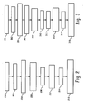
Fig. 2 depicts a first technique for using information from a scan to generate a plurality of studies. -
Fig. 3 depicts a second technique for using information from a scan to generate a plurality of studies. -
Fig. 4 depicts an exemplary histogram and region of interest definition. -
Fig. 5 depicts an exemplary image for planning a scan. - With reference to
FIG. 1 , a computed tomography (CT)scanner 10 includes arotating gantry 18 which rotates about the z-axis. Thegantry 18 supports anx-ray source 12 such as an x-ray tube. Thegantry 18 also supports an x-raysensitive detector 20 which subtends an angular arc on the opposite side of anexamination region 14. X-rays produced by thex-ray source 12 traverse theexamination region 14 and are detected by thedetector 20. - In one embodiment, the
detector 20 is a multi-slice detector which includes more than one row of detectors extending in the z-direction. Flat panel orother detector 20 configurations may also be implemented. Depending on the configuration of thedetector 20, thex-ray source 12 generates a generally fan, wedge, or cone shaped radiation beam. Moreover, a so-called fourth generation scanner configuration, in which thedetector 20 spans an arc of 360 degrees and remains stationary while thex-ray source 12 rotates, may also be implemented. - A patient support 16 such as a couch supports the patient in the
examination region 14. Thepatient support 16 is preferably movable in the z-direction. Acontroller 28 coordinates the various scan parameters as necessary to carry out a desired scan protocol. In a helical scan, movement of thesupport 16 and thegantry 18 are coordinated along with such that thex-ray source 12 and thedetectors 20 traverse a generally helical path with respect to the patient. In a surview scan, the movement of thesupport 16 and the gantry are coordinated such that thex-ray source 12 and the detectors traverse a generally linear path with respect to the patient, for example to provide an anterior-posterior or a lateral view of the patient. - Data collected by the
detector 20 are processed by areconstructor 20 to generate volumetric data indicative of the interior anatomy of the patient. The images are stored in asuitable memory 30 such as a computer disk, other volatile or non-volatile memory or other memory storage device. Thememory 30 is organized to store data indicative of a number of image series orstudies accession number 42, patient information 44, andlocalizer 46 and diagnostic 48 images. In this regard, it should be noted that the data associated with each series need not be in separate memory locations. Rather, the data may be arranged in suitable data structures and accessed using associated pointers, linked lists, or the like. - Images and other information generated from the data obtained by the scanner are further manipulated by one or more imaging computers or
workstations 36, which may also be used as the scanner console. The imaging computers orworkstations 36 typically include an operator interface having an output device such as a human readable display and/or film printer and an input device such as a keyboard and/or mouse. Thus, the operator may view and manipulate images, select desired scan protocols, initiate or terminate scans, and otherwise interact with thescanner 10. - The
scanner 10 may also be in operative communication with a computer information system such as one or both of a hospital information system/radiology information system (HIS/RIS) 38 or picture archiving and communication system (PACS)system 40, over a HL-7, DICOM or other suitable interface. - Turning now to
Figure 2 , a technique for using information from a CT scan to generate a plurality of studies or image series will be described. At 200, imaging requests are transferred from the computer information system such as the hospital HIS/RIS system 38 and received by theCT scanner 10. The imaging requests may include requests for separate scans that may be advantageously acquired in a single scan or requests to scan multiple regions for which there may be different informational requirements, for example requests covering one or more regions of the body such as the head, neck, chest, abdomen, or pelvis. Alternately, imaging requests may be entered manually by the operator through the operator interface or otherwise. - The CT scanner combines multiple procedure requests from the HIS/RIS system into one scan automatically based on internal rules and predefined protocols. Thus, for example, these rules my combine requests for separate study conveying the chest, abdomen, and pelvis into a single scan, with each study being generated according to a predefined study protocol. Alternatively, the operator can combine the requests manually. Another method may include a predefined request from the HIS/RIS system to be interpreted as a single scan that has to be split into multiple studies or series by the scanner (either automatically or manually).
- At 202, a volumetric localizer scan of the patient is obtained. The localizer scan is preferably a relatively low dose or relatively fast, high pitch helical scan of the patient which provides information of a quality sufficient for localization purposes but which may not be optimal for diagnostic purposes. Similarly, the reconstruction protocol is preferably selected to provide a relatively faster reconstruction time. The axial extent of the localizer scan corresponds approximately to the axial extent of the requested procedures. Alternately, the localizer scan may be a surview scan.
- At 204, information from the localizer scan is used to identify the relevant regions of the patient's anatomy. The regions correspond to the regions of the requested procedures.
- At 206, a diagnostic quality CT scan which includes the relevant regions of the patient's anatomy is planned, and the desired studies are defined.
- The identified anatomical regions are used to establish a region of interest for each of two or more studies. In the example of
Figure 4b , the location of region of interest for three studies - afirst study 602 in which the region of interest includes the patient's chest, asecond study 604 in which the region of interest includes the patient's abdomen, and athird study 606 in which the region of interest includes the patient's pelvis — is depicted. - As shown in
Figure 4b , the region of interest of thefirst study 602 overlaps with the region of interest of thesecond study 604, which in turn overlaps with the region of interest of thethird study 606. Thus, portions of the patient's anatomy may be included in more than one study, with images or other information being generated according to the protocol corresponding to each study. As will also be appreciated, there may be situations where it is desirable to arrange the regions of interests of the studies so that they do not overlap or so that there are gaps between them. - Again with reference to
Figure 4b , anoverview image 600 such as a maximum intensity projection (MIP) anterior posterior view or the patient's interior anatomy is generated from the localizer data and displayed on the operator interface, with the regions ofinterest overview image 600. Of course, other views, such as lateral views, volume visualized views, and the like, may also be displayed. The user may be afforded an opportunity to review and alter the region of interest definitions using the operator interface. Alternately, the definition of the regions of interest may proceed automatically without input from the operator. - While the above description has focused on a graphic display, the region of interest for the various studies can also be described in other ways. For example, the regions of interest can be described numerically with reference to the distance from a location on the
patient support 16, a location on the patient's anatomy, a coordinate in image space, the slice number, or the like. - Depending on the regions of interest, the purposes for which the study is being performed, user requirements and preferences, and the like, it is sometimes desirable to establish different study protocols for one or all of the
studies x-ray source 12 voltage or current, scan pitch, or collimation settings, in the case of a CT scanner). - In one embodiment, a default protocol is established for each study based on the region of interest of the study, the person requesting it, or other relevant characteristic. Thus, for example, the protocols used to generate images of the head, neck, and chest or requested by a different physician or physician group may have different default values. In another embodiment, some or all of the protocol information is entered by the operator. In another embodiment, the imaging request received from the computer information system would be used to establish the some or all of the protocols parameter values. Other or different parameters, or differing combinations of them, can also be implemented depending on the type or characteristics of a particular scanner or the requirements of a particular application.
- Returning to
Figure 2 , at 208, a diagnostic CT scan covering the desired regions of the patient's anatomy is obtained. In the example described above, the axial extent of the scan would include the patient's chest, abdomen, and pelvis. However, the scan need not be continuous over the patient's anatomy. In cases where there are gaps between the studies or the requested procedures, there may be corresponding gaps in the regions covered by the scan. - At 212, information from the diagnostic scan is used to generate the diagnostic image or images corresponding to each study, based on the study protocol established for each study.
- At 214, the information associated with each study is stored in
memory 30. With reference toFigure 1 , a unique identifier such anaccession number 42, together with the relevant patient information 44, localizer image(s) 46, and diagnostic image(s) 48 are associated with eachstudy - Returning now to
Figure 2 , at 216, the studies are sent to a computer information system such as thePACS system 40 and a HIS/RIS or computer information system is notified that the studies corresponding to the requested procedures have been generated. - While the steps of generating the images corresponding to each
study 212, storing thestudies 214, and sending the studies to an information system are described serially, these steps may also be performed either partially or completely in parallel. Thus, for example, the information associated with a first study can be generated, stored, and sent to the information system before processing the next study, and so on. - Turning now to
Figure 3 , another technique for using information from a CT scan to generate a plurality of studies or image series will be described. At 300, imaging requests are transferred from a computer information system such as the hospital HIS/RIS system 26 and received by theCT scanner 10. Alternately, such the requests may be entered manually by the operator through the operator interface or otherwise. - At 302, a localizer scan of the patient is obtained and data reconstructed. The localizer scan is preferably a relatively low dose surview scan providing a two dimensional anterior-posterior and/or lateral view of the patient. The localizer scan provides information of a quality sufficient for localization purposes but which may not be optimal for diagnostic purposes. The axial extent of the localizer scan corresponds approximately to the axial extent of the requested procedures. Alternately, the localizer scan may be a low dose helical scan of the patient which provides volumetric information about the patient's anatomy.
- At 304, the operator uses the CT information from the localizer scan to establish the scan bounds for a diagnostic quality scan (e.g., the scan staring location and end location, as well as the scan field of view) which encompasses the relevant regions of interest. In this regard, it is not necessary for the operator to establish bounds for each region of interest, but rather the extent of the scan as a whole.
- At 306, a diagnostic quality CT scan which includes the relevant regions of the patient's anatomy is planned.
- As shown schematically in
Figure 5 , anoverview image 500 such as a maximum intensity projection (MIP) anterior posterior view or the patient's interior anatomy is generated from the localizer data and displayed on the operator interface, with the regions ofinterest 502 to be covered by the scan indicated on theoverview image 500. In the example ofFigure 5 , theregion 502 includes the patient's head and neck. It should be noted that, depending on the regions of interest, the scan may cover more than one non-contiguous region. Of course, other views, such as lateral views, volume visualized views, and the like, may also be displayed. The user may be afforded an opportunity to review and alter the axial extent of the scan using the operator interface. Alternately, the scan extent may be established automatically without operator review or feedback. - While the above has been described graphically, the region to be covered by the scan may also be depicted in other ways. For example, the locations can be depicted numerically with reference to the distance from a location on the
patient support 16, a location on the patient's anatomy, the slice number, or the like. - A scan protocol is also established for the scan.
- Returning to
Figure 3 , a diagnostic CT scan covering the desired region of the patient's anatomy is obtained at 308. In the example described above, the axial extent of the scan would include the patient's head and neck. Again, however, the scan need not be continuous over the patient's anatomy. In cases where there are gaps between relevant regions, there may be corresponding gaps in the data collected by the scan. The data from the scan is reconstructed to create volumetric data indicative of the patient's interior anatomy, preferably using a reconstruction protocol selected to provide a relatively faster reconstruction time. This reconstruction provides information of a quality sufficient for localization purposes but which may not be optimal for diagnostic purposes. - At 310, information from the CT scan obtained at
step 308 is analyzed to identify the relevant regions of the patient's anatomy. The relevant regions may also be identified based on the images generated from the volumetric data as they evolve during the course of an ongoing reconstruction. - At 311, the regions of the anatomy identified in
step 308 are used to defme multiple studies or series as generally described above in connection withstep 206. Following the example ofFigure 5 , two studies - a first study in which the region of interest includes the patient's head, and a second study in which the region of interest includes the patient's neck, would be defined. Of course, studies similar to those defined in the example ofFigure 4 , or other desired studies, could also be defined. - At 312, information from the diagnostic scan is used to generate one or more diagnostic images corresponding to each study, based on the study protocol established for each study. Thus, each study may have different parameters (filters, rendering modes, 3D displays, etc.).
- At 314, information associated with each study is stored in
memory 30. With reference toFigure 1 , a unique identifier such as anaccession number 42, together with the relevant patient information 44, localizer image(s) 46, and diagnostic image(s) 48 are associated with eachstudy - Returning to now to
Figure 3 , at 314, the studies are sent to a computer information system such as thePACS system 40, and a HIS/RIS or other computer information system is also notified that studies corresponding to the multiple requested procedures have been generated. - With reference to
Figure 4 , the identification of the relevant regions of the patient's anatomy will now be described in greater detail. The volumetric data generated by a scan can be classified into a plurality of categories. The results of the classification, the calculation of the cross section of the patient's anatomy as a function of axial position, and morphological knowledge can be used to automatically identify regions of the anatomy. - With reference to
Figure 4a , the pixels in each axial image slice are classified asair 650,soft tissue 652, orbone 654 as a function of x-ray attenuation. In scans using contrast agent, regions including contrast agent can be classified as bone, or may classified separately. The result is a graph or histogram in which the abscissa represents the slice number or location in the axial (z) direction and the ordinate represents the number of pixels plotted as a ratio to the mean for each class. - The partition of the
chest 602,abdomen 604, andpelvis 606 is carried out in three main steps: identifying and segmenting the lungs, finding the pelvis and pubic bone, and identifying the diaphragm. - The lungs are identified using heuristics for finding air filled objects inside the body or partially inside the body (where lungs are cut off at the image border in the case of scans having a small field of view). Next, the lungs are segmented and the top and bottom borders of the lungs identified. The top 608 and bottom 610 borders of the
chest region 602 are established slightly beyond the top and borders of the lungs. - The slices containing the pelvis and pubic bones are then identified on the histogram using feature detection techniques as are known to those skilled in the art. For studies including contrast the pelvis and pubic bones are preferably differentiated from the contrast for a more accurate identification. The top 612 and
bottom 614 of thepelvic region 606 are established slightly beyond the pelvis and pubic bones, respectively. - The diaphragm is identified by evaluating the histogram for a falloff in body pixels located near the bottom of the lungs. The diaphragm and top of the pelvis bone define the top 618 and
bottom 616 of the abdomen, respectively. - To identify the head and neck, the image is first preprocessed using feature detection to remove the bed and head holder. A histogram similar to
Figure 4b is generated, and the body area at each slice is also calculated. The interface between the head and neck is ascertained by evaluating the amount of bone and the body area. - Where one or more slices have not been assigned to a region of interest, the slices are preferably assigned to at least one region of interest near the slice. This avoids situations in which one or more slices are not assigned to a study, and thus not presented to the radiologist to review.
- As will be appreciated, the above techniques can readily be extended to delineate between other anatomical regions, such as the torso and the legs, and the thighs and knees, and shins and spine.
- Of course, other variations on the above techniques are also possible. Thus, for example, the one or both of the localizer scans 202, 302 may be omitted and the
scan planning - Moreover, the scanner need not be in communication with a computer information system. Also, the technique has been described as being performed on the scanner or computers associated with the scanner. As will be appreciated, all or a portion of techniques may be performed using computer systems or operator interfaces which are located remotely from the scanner but capable of receiving or exchanging data by way of a local or wide area computer network, the internet, wireless communications, portable physical storage media, a picture archiving and communications (PACS) system, or the like.
- The invention has been described with reference to the preferred embodiments. Of course, modifications and alterations will occur to others upon reading and understanding the preceding description. It is intended that the invention be construed as including all such modifications and alterations insofar as they come within the scope of the appended claims or the equivalents thereof.
Claims (23)
- A computer-implemented method of generating at least first and second studies using information from a single imaging scan of a patient's anatomy, said method comprising:- obtaining a localizer scan which provides information indicative of the interior anatomy of a patient, including information indicative of at least first and second regions (602, 604) of the patient's anatomy;using information from the localizer scan to determine a location of the first and second regions (602, 604);planning an imaging scan which includes said first and second regions (602, 604) and defining first and second studies wherein the first and second study comprises each a corresponding study protocol, wherein the first study protocol includes a first scan protocol and at least one of a first reconstruction protocol and a first display protocol and wherein the second study protocol includes a second scan protocol which differs from the first scan protocol in one or more parameters relating to the scanning operation and at least one of a second reconstruction protocol and a second display protocol;obtaining an imaging scan based on the defined studies which provides information indicative of the interior anatomy of a patient in at least the first and second regions (602, 604);using said first study protocol and information from the imaging scan to generate at least one image indicative of the interior anatomy of the patient in the first region (602);using said second study protocol and information from the imaging scan to generate at least one image indicative of the interior anatomy of the patient in the second region (604);storing information associated with the first and second studies (32a, 32b) in a computer readable storage medium (30).
- The method of claim 1 further comprising
using information from the localizer scan to determine a third region (606) of the patient's anatomy;
using a third study protocol of a third study (32c) and information from the imaging scan of the patient's anatomy to generate a third study (32c), wherein the third study protocol includes at least one of a third scan protocol, a third reconstruction protocol and a third display protocol, and wherein the third study (32c) includes at least one image indicative of the interior of the anatomy of the patient in the third region (606); and
storing information associated with the third study (32c) in the computer readable storage medium (30). - The method of claim 1 further comprising using information from the imaging scan to define the first and second regions (602,604).
- The method of claim 3 further comprising using information from the imaging scan to generate volumetric data indicative of the patient's anatomy and wherein the step of using information from the imaging scan to define the first and second regions (602, 604) includes classifying the volumetric data into a plurality of categories (650, 652, 654), using morphological knowledge of the patient's anatomy, and evaluating the cross sectional area of the patient's anatomy.
- The method of claim 1 wherein the first study protocol includes a first reconstruction protocol and the second study protocol includes a second reconstruction protocol.
- The method of claim 1 wherein the first study protocol includes a first display protocol and the second study protocol includes a second display protocol.
- The method of claim 6 wherein the display protocols each define at least one of axial, coronal, and saggital images.
- The method of claim 1 wherein the localizer scan is a surview scan.
- The method of claim 1 wherein the localizer scan is a volumetric scan.
- The method of claim 1 wherein the localizer scan is a relatively low dose helical computed tomography scan.
- The method of claim 1 wherein using information from the localizer scan to determine the location of the first and second regions (602, 604) includes locating the patient's lungs, pelvis bone, and diaphragm.
- The method of claim 1 wherein the first and second studies (32a, 32b) each include an overview image (600) of the first and second regions (602, 604) and an identifier which uniquely identifies the study, and wherein the first and second regions (602, 604) are indicated on the overview image (600).
- The method of claim 1 further comprising using information from the localizer scan to generate volumetric data indicative of the patient's anatomy and wherein the step of using information from the localizer scan to determine the location of the first and second regions (602, 604) includes classifying the volumetric data into a plurality of categories (650, 652, 654), using morphological knowledge of the patient's anatomy, and evaluating the cross sectional area of the patient's anatomy.
- The method of claim 1 wherein the first and second regions (602, 604) overlap.
- The method of claim 1 further comprising:receiving a request for a first study of a first requested region of the patient's anatomy and a request for a second study of a second requested region of the patient's anatomy;defining an extent of the imaging scan, wherein the extent includes the first and second requested regions of the patient's anatomy.
- The method of claim 1 further comprising notifying a computer information system (38) that the first and second studies (32a, 32b) have been generated.
- The method of claim 1 further comprising:receiving a request for a first study of the first region (602) and a request for a second study of the second region (604);obtaining the imaging scan of at least the first and second regions (602, 604).
- The method of claim 16 wherein the requests are received from a computer information system (38).
- The method of claim 1 wherein the imaging scan is a computed tomography scan.
- The method of claim 1 wherein the imaging scan is a computed tomography scan, and wherein first and second scan protocols respectively included in the first and second study protocols each include x-ray tube voltage and current.
- The method of claim 1 wherein the first and second regions are axial regions.
- An apparatus for generating at least first and second studies using information from a single imaging scan of a patient's anatomy, said apparatus comprising:means for obtaining a localizer scan which provides information indicative of the interior anatomy of a patient, including information indicative of at least first and second regions (602, 604) of the patient's anatomy;means for using information from the localizer scan to determine a location of the first and second regions (602, 604);means for planning an imaging scan which includes said first and second regions (602, 604) and defining first and second studies wherein the first and second study comprises each a corresponding study protocol, wherein the first study protocol includes a first scan protocol and at least one of a first reconstruction protocol and a first display protocol and wherein the second study protocol includes a second scan protocol which differs from the first scan protocol in one or more parameters relating to the scanning operation and at least one of a second reconstruction protocol and a second display protocol;means for obtaining an imaging scan based on the defined studies which provides information indicative of the interior anatomy of a patient in at least the first and second regions (602, 604);means for using said first study protocol and information from the imaging scan to generate at least one image indicative of the interior anatomy of the patient in the first region (602);means for using said second study protocol and information from the imaging scan to generate at least one image indicative of the interior anatomy of the patient in the second region (604);means for storing information associated with the first and second studies (32a, 32b) in a computer readable storage medium (30).
- The apparatus of claim 22 wherein the first and second regions are axial regions.
Applications Claiming Priority (2)
| Application Number | Priority Date | Filing Date | Title |
|---|---|---|---|
| US59576005P | 2005-08-03 | 2005-08-03 | |
| PCT/IB2006/052580 WO2007015196A2 (en) | 2005-08-03 | 2006-07-27 | Method and apparatus for generating multiple studies |
Publications (2)
| Publication Number | Publication Date |
|---|---|
| EP1913504A2 EP1913504A2 (en) | 2008-04-23 |
| EP1913504B1 true EP1913504B1 (en) | 2009-12-23 |
Family
ID=37564359
Family Applications (1)
| Application Number | Title | Priority Date | Filing Date |
|---|---|---|---|
| EP06780228A Active EP1913504B1 (en) | 2005-08-03 | 2006-07-27 | Method and apparatus for generating multiple studies |
Country Status (7)
| Country | Link |
|---|---|
| US (1) | US8548122B2 (en) |
| EP (1) | EP1913504B1 (en) |
| JP (1) | JP5139289B2 (en) |
| CN (1) | CN101233521B (en) |
| AT (1) | ATE453160T1 (en) |
| DE (1) | DE602006011333D1 (en) |
| WO (1) | WO2007015196A2 (en) |
Families Citing this family (34)
| Publication number | Priority date | Publication date | Assignee | Title |
|---|---|---|---|---|
| US7983457B2 (en) * | 2005-11-23 | 2011-07-19 | General Electric Company | Method and system for automatically determining regions in a scanned object |
| DE102006004618A1 (en) * | 2006-02-01 | 2007-08-09 | Siemens Ag | Workflow-based management of medical image data |
| JP5132182B2 (en) * | 2007-04-25 | 2013-01-30 | キヤノン株式会社 | MEDICAL EXAMINATION SYSTEM AND ITS PROCESSING METHOD, PROGRAM, AND STORAGE MEDIUM |
| WO2009080866A1 (en) * | 2007-12-20 | 2009-07-02 | Palodex Group Oy | Method and arrangement for medical imaging |
| JP5346859B2 (en) * | 2009-04-15 | 2013-11-20 | 富士フイルム株式会社 | MEDICAL IMAGE MANAGEMENT DEVICE, METHOD, AND PROGRAM |
| US10191127B2 (en) | 2012-10-31 | 2019-01-29 | Aspect Imaging Ltd. | Magnetic resonance imaging system including a protective cover and a camera |
| US11278461B2 (en) | 2010-07-07 | 2022-03-22 | Aspect Imaging Ltd. | Devices and methods for a neonate incubator, capsule and cart |
| US10076266B2 (en) | 2010-07-07 | 2018-09-18 | Aspect Imaging Ltd. | Devices and methods for a neonate incubator, capsule and cart |
| US9597246B2 (en) | 2010-09-16 | 2017-03-21 | Aspect Imaging Ltd. | Premature neonate closed life support system |
| US10794975B2 (en) | 2010-09-16 | 2020-10-06 | Aspect Imaging Ltd. | RF shielding channel in MRI-incubator's closure assembly |
| JP5774447B2 (en) * | 2011-10-28 | 2015-09-09 | ジーイー・メディカル・システムズ・グローバル・テクノロジー・カンパニー・エルエルシー | X-ray CT apparatus, dose calculation method and program |
| CN103385728A (en) * | 2012-05-07 | 2013-11-13 | 上海西门子医疗器械有限公司 | X ray computed tomography method and X ray computed tomography system |
| KR101463420B1 (en) | 2013-01-04 | 2014-11-19 | 삼성전자주식회사 | Method for imaging magnetic resonance image and appratus using the same thereof |
| US8908832B2 (en) * | 2013-03-11 | 2014-12-09 | Shimadzu Corporation | Radiographic apparatus and method for the same |
| US10070839B2 (en) * | 2013-03-15 | 2018-09-11 | PME IP Pty Ltd | Apparatus and system for rule based visualization of digital breast tomosynthesis and other volumetric images |
| WO2014174461A2 (en) * | 2013-04-24 | 2014-10-30 | Koninklijke Philips N.V. | Image visualization |
| DE202013105212U1 (en) | 2013-11-17 | 2014-02-13 | Aspect Imaging Ltd. | Locking device of an MRI incubator |
| EP3071108A1 (en) * | 2013-11-18 | 2016-09-28 | Koninklijke Philips N.V. | One or more two dimensional (2d) planning projection images based on three dimensional (3d) pre-scan image data |
| US10061979B2 (en) | 2014-09-28 | 2018-08-28 | Koninklijke Philips N.V. | Image processing apparatus and method |
| US9652846B1 (en) * | 2015-10-22 | 2017-05-16 | International Business Machines Corporation | Viewpoint recognition in computer tomography images |
| CN105997124B (en) * | 2016-04-17 | 2018-09-21 | 黄启标 | Abdomen angiography scans diagnostic device |
| JP6870920B2 (en) * | 2016-05-19 | 2021-05-12 | キヤノンメディカルシステムズ株式会社 | X-ray CT device and X-ray detector |
| US11287497B2 (en) | 2016-08-08 | 2022-03-29 | Aspect Imaging Ltd. | Device, system and method for obtaining a magnetic measurement with permanent magnets |
| US10224135B2 (en) | 2016-08-08 | 2019-03-05 | Aspect Imaging Ltd. | Device, system and method for obtaining a magnetic measurement with permanent magnets |
| US11988730B2 (en) | 2016-08-08 | 2024-05-21 | Aspect Imaging Ltd. | Device, system and method for obtaining a magnetic measurement with permanent magnets |
| US11399732B2 (en) | 2016-09-12 | 2022-08-02 | Aspect Imaging Ltd. | RF coil assembly with a head opening and isolation channel |
| CN106725570B (en) * | 2016-12-30 | 2019-12-20 | 上海联影医疗科技有限公司 | Imaging method and system |
| JP7098338B2 (en) * | 2017-01-25 | 2022-07-11 | キヤノンメディカルシステムズ株式会社 | X-ray CT device and imaging management device |
| US11317886B2 (en) | 2017-01-25 | 2022-05-03 | Canon Medical Systems Corporation | X-ray CT apparatus and imaging management apparatus |
| JP7199839B2 (en) * | 2018-06-04 | 2023-01-06 | キヤノンメディカルシステムズ株式会社 | X-ray CT apparatus and medical image processing method |
| JP7179497B2 (en) * | 2018-06-04 | 2022-11-29 | キヤノンメディカルシステムズ株式会社 | X-ray CT apparatus and image generation method |
| US11051780B2 (en) * | 2018-07-25 | 2021-07-06 | Siemens Healthcare Gmbh | Automatically generating synchronized view and level of concordance of diagnostic exams |
| CN109549659A (en) * | 2019-01-08 | 2019-04-02 | 沈阳东软医疗系统有限公司 | A kind of method and system automatically obtaining scanned position locating plate |
| JP7778569B2 (en) * | 2019-05-14 | 2025-12-02 | コーニンクレッカ フィリップス エヌ ヴェ | Protocol-dependent 2D prescan projection images based on 3D prescan volumetric image data |
Family Cites Families (13)
| Publication number | Priority date | Publication date | Assignee | Title |
|---|---|---|---|---|
| US6501818B1 (en) * | 1997-11-26 | 2002-12-31 | Ge Medical Systems Global Technology Company, Llc | Apparatus and methods for displaying computed tomography fluoroscopy images including data transfer provided over a network |
| US6154516A (en) * | 1998-09-04 | 2000-11-28 | Picker International, Inc. | Cardiac CT system |
| JP2002095655A (en) * | 2000-09-26 | 2002-04-02 | Shimadzu Corp | CT device |
| JP2002219122A (en) | 2000-11-24 | 2002-08-06 | Siemens Ag | Medical system architecture |
| JP3961249B2 (en) * | 2001-08-28 | 2007-08-22 | ジーイー・メディカル・システムズ・グローバル・テクノロジー・カンパニー・エルエルシー | X-ray CT system, gantry apparatus, operation console and control method thereof, program code, and storage medium |
| US6678399B2 (en) * | 2001-11-23 | 2004-01-13 | University Of Chicago | Subtraction technique for computerized detection of small lung nodules in computer tomography images |
| US20040068167A1 (en) * | 2002-09-13 | 2004-04-08 | Jiang Hsieh | Computer aided processing of medical images |
| DE10254943A1 (en) | 2002-11-25 | 2004-06-17 | Siemens Ag | Producing volume data record for medical examination involves transforming first volume data record, generating third in which second is filtered so uninteresting object structures are filtered out |
| US7177453B2 (en) * | 2002-11-26 | 2007-02-13 | General Electric Company | Method and apparatus for partitioning a volume |
| US7756725B2 (en) | 2002-12-31 | 2010-07-13 | DeJarnette Research Systems, Inc | Breakaway interfacing of radiological images with work orders |
| EP1603461A2 (en) * | 2003-03-10 | 2005-12-14 | Philips Intellectual Property & Standards GmbH | Device and method for adapting the recording parameters of a radiograph |
| US6901132B2 (en) * | 2003-06-26 | 2005-05-31 | General Electric Company | System and method for scanning an object in tomosynthesis applications |
| JP2005177203A (en) | 2003-12-22 | 2005-07-07 | Ge Medical Systems Global Technology Co Llc | Multi-position CT image generation method and X-ray CT apparatus |
-
2006
- 2006-07-27 EP EP06780228A patent/EP1913504B1/en active Active
- 2006-07-27 JP JP2008524646A patent/JP5139289B2/en active Active
- 2006-07-27 CN CN200680028400.7A patent/CN101233521B/en active Active
- 2006-07-27 DE DE602006011333T patent/DE602006011333D1/en active Active
- 2006-07-27 AT AT06780228T patent/ATE453160T1/en not_active IP Right Cessation
- 2006-07-27 US US11/997,654 patent/US8548122B2/en active Active
- 2006-07-27 WO PCT/IB2006/052580 patent/WO2007015196A2/en not_active Ceased
Also Published As
| Publication number | Publication date |
|---|---|
| EP1913504A2 (en) | 2008-04-23 |
| JP2009502403A (en) | 2009-01-29 |
| JP5139289B2 (en) | 2013-02-06 |
| WO2007015196A2 (en) | 2007-02-08 |
| DE602006011333D1 (en) | 2010-02-04 |
| CN101233521A (en) | 2008-07-30 |
| US8548122B2 (en) | 2013-10-01 |
| ATE453160T1 (en) | 2010-01-15 |
| WO2007015196A3 (en) | 2007-07-05 |
| US20080234571A1 (en) | 2008-09-25 |
| CN101233521B (en) | 2015-08-19 |
Similar Documents
| Publication | Publication Date | Title |
|---|---|---|
| US8548122B2 (en) | Method and apparatus for generating multiple studies | |
| US8386273B2 (en) | Medical image diagnostic apparatus, picture archiving communication system server, image reference apparatus, and medical image diagnostic system | |
| US7756314B2 (en) | Methods and systems for computer aided targeting | |
| US10470733B2 (en) | X-ray CT device and medical information management device | |
| US6574304B1 (en) | Computer aided acquisition of medical images | |
| EP2443614B1 (en) | Imaging procedure planning | |
| EP3045114B1 (en) | Control apparatus for controlling tomosynthesis imaging, radiographing apparatus, control system, control method, and recording medium | |
| Bachar et al. | Image quality and localization accuracy in C‐arm tomosynthesis‐guided head and neck surgery | |
| JP4786246B2 (en) | Image processing apparatus and image processing system | |
| JP2005103263A (en) | Method of operating image forming inspection apparatus having tomographic capability and X-ray computed tomography apparatus | |
| JP6841894B1 (en) | Medical equipment and programs | |
| JP2018000943A (en) | Medical image diagnostic apparatus and medical image processor | |
| JP7144129B2 (en) | Medical image diagnosis device and medical information management device | |
| JP6598653B2 (en) | Medical information processing apparatus and medical information processing system | |
| JP7199839B2 (en) | X-ray CT apparatus and medical image processing method | |
| EP4197475B1 (en) | Technique of determining a scan region to be imaged by a medical image acquisition device | |
| JP6956514B2 (en) | X-ray CT device and medical information management device | |
| US20050148861A1 (en) | Methods and systems for image selection and display | |
| JP7553328B2 (en) | Medical image processing device, medical image processing method, and program | |
| US9474449B2 (en) | Single scan multi-procedure imaging |
Legal Events
| Date | Code | Title | Description |
|---|---|---|---|
| PUAI | Public reference made under article 153(3) epc to a published international application that has entered the european phase |
Free format text: ORIGINAL CODE: 0009012 |
|
| 17P | Request for examination filed |
Effective date: 20080303 |
|
| AK | Designated contracting states |
Kind code of ref document: A2 Designated state(s): AT BE BG CH CY CZ DE DK EE ES FI FR GB GR HU IE IS IT LI LT LU LV MC NL PL PT RO SE SI SK TR |
|
| 17Q | First examination report despatched |
Effective date: 20080707 |
|
| GRAP | Despatch of communication of intention to grant a patent |
Free format text: ORIGINAL CODE: EPIDOSNIGR1 |
|
| DAX | Request for extension of the european patent (deleted) | ||
| GRAS | Grant fee paid |
Free format text: ORIGINAL CODE: EPIDOSNIGR3 |
|
| GRAA | (expected) grant |
Free format text: ORIGINAL CODE: 0009210 |
|
| AK | Designated contracting states |
Kind code of ref document: B1 Designated state(s): AT BE BG CH CY CZ DE DK EE ES FI FR GB GR HU IE IS IT LI LT LU LV MC NL PL PT RO SE SI SK TR |
|
| REG | Reference to a national code |
Ref country code: GB Ref legal event code: FG4D |
|
| REG | Reference to a national code |
Ref country code: CH Ref legal event code: EP |
|
| REG | Reference to a national code |
Ref country code: IE Ref legal event code: FG4D |
|
| REF | Corresponds to: |
Ref document number: 602006011333 Country of ref document: DE Date of ref document: 20100204 Kind code of ref document: P |
|
| REG | Reference to a national code |
Ref country code: NL Ref legal event code: VDEP Effective date: 20091223 |
|
| PG25 | Lapsed in a contracting state [announced via postgrant information from national office to epo] |
Ref country code: SE Free format text: LAPSE BECAUSE OF FAILURE TO SUBMIT A TRANSLATION OF THE DESCRIPTION OR TO PAY THE FEE WITHIN THE PRESCRIBED TIME-LIMIT Effective date: 20091223 Ref country code: FI Free format text: LAPSE BECAUSE OF FAILURE TO SUBMIT A TRANSLATION OF THE DESCRIPTION OR TO PAY THE FEE WITHIN THE PRESCRIBED TIME-LIMIT Effective date: 20091223 Ref country code: LT Free format text: LAPSE BECAUSE OF FAILURE TO SUBMIT A TRANSLATION OF THE DESCRIPTION OR TO PAY THE FEE WITHIN THE PRESCRIBED TIME-LIMIT Effective date: 20091223 |
|
| LTIE | Lt: invalidation of european patent or patent extension |
Effective date: 20091223 |
|
| PG25 | Lapsed in a contracting state [announced via postgrant information from national office to epo] |
Ref country code: SI Free format text: LAPSE BECAUSE OF FAILURE TO SUBMIT A TRANSLATION OF THE DESCRIPTION OR TO PAY THE FEE WITHIN THE PRESCRIBED TIME-LIMIT Effective date: 20091223 Ref country code: PL Free format text: LAPSE BECAUSE OF FAILURE TO SUBMIT A TRANSLATION OF THE DESCRIPTION OR TO PAY THE FEE WITHIN THE PRESCRIBED TIME-LIMIT Effective date: 20091223 Ref country code: LV Free format text: LAPSE BECAUSE OF FAILURE TO SUBMIT A TRANSLATION OF THE DESCRIPTION OR TO PAY THE FEE WITHIN THE PRESCRIBED TIME-LIMIT Effective date: 20091223 |
|
| PG25 | Lapsed in a contracting state [announced via postgrant information from national office to epo] |
Ref country code: AT Free format text: LAPSE BECAUSE OF FAILURE TO SUBMIT A TRANSLATION OF THE DESCRIPTION OR TO PAY THE FEE WITHIN THE PRESCRIBED TIME-LIMIT Effective date: 20091223 |
|
| PG25 | Lapsed in a contracting state [announced via postgrant information from national office to epo] |
Ref country code: NL Free format text: LAPSE BECAUSE OF FAILURE TO SUBMIT A TRANSLATION OF THE DESCRIPTION OR TO PAY THE FEE WITHIN THE PRESCRIBED TIME-LIMIT Effective date: 20091223 Ref country code: IS Free format text: LAPSE BECAUSE OF FAILURE TO SUBMIT A TRANSLATION OF THE DESCRIPTION OR TO PAY THE FEE WITHIN THE PRESCRIBED TIME-LIMIT Effective date: 20100423 Ref country code: ES Free format text: LAPSE BECAUSE OF FAILURE TO SUBMIT A TRANSLATION OF THE DESCRIPTION OR TO PAY THE FEE WITHIN THE PRESCRIBED TIME-LIMIT Effective date: 20100403 Ref country code: BG Free format text: LAPSE BECAUSE OF FAILURE TO SUBMIT A TRANSLATION OF THE DESCRIPTION OR TO PAY THE FEE WITHIN THE PRESCRIBED TIME-LIMIT Effective date: 20100323 Ref country code: EE Free format text: LAPSE BECAUSE OF FAILURE TO SUBMIT A TRANSLATION OF THE DESCRIPTION OR TO PAY THE FEE WITHIN THE PRESCRIBED TIME-LIMIT Effective date: 20091223 Ref country code: RO Free format text: LAPSE BECAUSE OF FAILURE TO SUBMIT A TRANSLATION OF THE DESCRIPTION OR TO PAY THE FEE WITHIN THE PRESCRIBED TIME-LIMIT Effective date: 20091223 Ref country code: PT Free format text: LAPSE BECAUSE OF FAILURE TO SUBMIT A TRANSLATION OF THE DESCRIPTION OR TO PAY THE FEE WITHIN THE PRESCRIBED TIME-LIMIT Effective date: 20100423 |
|
| PG25 | Lapsed in a contracting state [announced via postgrant information from national office to epo] |
Ref country code: BE Free format text: LAPSE BECAUSE OF FAILURE TO SUBMIT A TRANSLATION OF THE DESCRIPTION OR TO PAY THE FEE WITHIN THE PRESCRIBED TIME-LIMIT Effective date: 20091223 Ref country code: SK Free format text: LAPSE BECAUSE OF FAILURE TO SUBMIT A TRANSLATION OF THE DESCRIPTION OR TO PAY THE FEE WITHIN THE PRESCRIBED TIME-LIMIT Effective date: 20091223 Ref country code: CZ Free format text: LAPSE BECAUSE OF FAILURE TO SUBMIT A TRANSLATION OF THE DESCRIPTION OR TO PAY THE FEE WITHIN THE PRESCRIBED TIME-LIMIT Effective date: 20091223 |
|
| PG25 | Lapsed in a contracting state [announced via postgrant information from national office to epo] |
Ref country code: GR Free format text: LAPSE BECAUSE OF FAILURE TO SUBMIT A TRANSLATION OF THE DESCRIPTION OR TO PAY THE FEE WITHIN THE PRESCRIBED TIME-LIMIT Effective date: 20100324 Ref country code: CY Free format text: LAPSE BECAUSE OF FAILURE TO SUBMIT A TRANSLATION OF THE DESCRIPTION OR TO PAY THE FEE WITHIN THE PRESCRIBED TIME-LIMIT Effective date: 20091223 |
|
| PLBE | No opposition filed within time limit |
Free format text: ORIGINAL CODE: 0009261 |
|
| STAA | Information on the status of an ep patent application or granted ep patent |
Free format text: STATUS: NO OPPOSITION FILED WITHIN TIME LIMIT |
|
| 26N | No opposition filed |
Effective date: 20100924 |
|
| PG25 | Lapsed in a contracting state [announced via postgrant information from national office to epo] |
Ref country code: DK Free format text: LAPSE BECAUSE OF FAILURE TO SUBMIT A TRANSLATION OF THE DESCRIPTION OR TO PAY THE FEE WITHIN THE PRESCRIBED TIME-LIMIT Effective date: 20091223 |
|
| PG25 | Lapsed in a contracting state [announced via postgrant information from national office to epo] |
Ref country code: MC Free format text: LAPSE BECAUSE OF NON-PAYMENT OF DUE FEES Effective date: 20100731 |
|
| REG | Reference to a national code |
Ref country code: CH Ref legal event code: PL |
|
| GBPC | Gb: european patent ceased through non-payment of renewal fee |
Effective date: 20100727 |
|
| PG25 | Lapsed in a contracting state [announced via postgrant information from national office to epo] |
Ref country code: IT Free format text: LAPSE BECAUSE OF FAILURE TO SUBMIT A TRANSLATION OF THE DESCRIPTION OR TO PAY THE FEE WITHIN THE PRESCRIBED TIME-LIMIT Effective date: 20091223 |
|
| PG25 | Lapsed in a contracting state [announced via postgrant information from national office to epo] |
Ref country code: LI Free format text: LAPSE BECAUSE OF NON-PAYMENT OF DUE FEES Effective date: 20100731 Ref country code: CH Free format text: LAPSE BECAUSE OF NON-PAYMENT OF DUE FEES Effective date: 20100731 |
|
| PG25 | Lapsed in a contracting state [announced via postgrant information from national office to epo] |
Ref country code: IE Free format text: LAPSE BECAUSE OF NON-PAYMENT OF DUE FEES Effective date: 20100727 Ref country code: GB Free format text: LAPSE BECAUSE OF NON-PAYMENT OF DUE FEES Effective date: 20100727 |
|
| PG25 | Lapsed in a contracting state [announced via postgrant information from national office to epo] |
Ref country code: LU Free format text: LAPSE BECAUSE OF NON-PAYMENT OF DUE FEES Effective date: 20100727 Ref country code: HU Free format text: LAPSE BECAUSE OF FAILURE TO SUBMIT A TRANSLATION OF THE DESCRIPTION OR TO PAY THE FEE WITHIN THE PRESCRIBED TIME-LIMIT Effective date: 20100624 |
|
| PG25 | Lapsed in a contracting state [announced via postgrant information from national office to epo] |
Ref country code: TR Free format text: LAPSE BECAUSE OF FAILURE TO SUBMIT A TRANSLATION OF THE DESCRIPTION OR TO PAY THE FEE WITHIN THE PRESCRIBED TIME-LIMIT Effective date: 20091223 |
|
| REG | Reference to a national code |
Ref country code: DE Ref legal event code: R081 Ref document number: 602006011333 Country of ref document: DE Owner name: KONINKLIJKE PHILIPS N.V., NL Free format text: FORMER OWNER: KONINKLIJKE PHILIPS ELECTRONICS N.V., EINDHOVEN, NL Effective date: 20140328 |
|
| REG | Reference to a national code |
Ref country code: FR Ref legal event code: CA Effective date: 20141126 Ref country code: FR Ref legal event code: CD Owner name: KONINKLIJKE PHILIPS ELECTRONICS N.V., NL Effective date: 20141126 |
|
| REG | Reference to a national code |
Ref country code: FR Ref legal event code: PLFP Year of fee payment: 11 |
|
| REG | Reference to a national code |
Ref country code: FR Ref legal event code: PLFP Year of fee payment: 12 |
|
| REG | Reference to a national code |
Ref country code: FR Ref legal event code: PLFP Year of fee payment: 13 |
|
| REG | Reference to a national code |
Ref country code: DE Ref legal event code: R079 Ref document number: 602006011333 Country of ref document: DE Free format text: PREVIOUS MAIN CLASS: G06F0019000000 Ipc: G16Z0099000000 |
|
| REG | Reference to a national code |
Ref country code: DE Ref legal event code: R084 Ref document number: 602006011333 Country of ref document: DE |
|
| PGFP | Annual fee paid to national office [announced via postgrant information from national office to epo] |
Ref country code: DE Payment date: 20250728 Year of fee payment: 20 |
|
| PGFP | Annual fee paid to national office [announced via postgrant information from national office to epo] |
Ref country code: FR Payment date: 20250725 Year of fee payment: 20 |