EP1912276B1 - Quarter wave plate - Google Patents
Quarter wave plate Download PDFInfo
- Publication number
- EP1912276B1 EP1912276B1 EP07075901.4A EP07075901A EP1912276B1 EP 1912276 B1 EP1912276 B1 EP 1912276B1 EP 07075901 A EP07075901 A EP 07075901A EP 1912276 B1 EP1912276 B1 EP 1912276B1
- Authority
- EP
- European Patent Office
- Prior art keywords
- grooves
- quarter wave
- wave plate
- plate
- quarter
- Prior art date
- Legal status (The legal status is an assumption and is not a legal conclusion. Google has not performed a legal analysis and makes no representation as to the accuracy of the status listed.)
- Expired - Lifetime
Links
- 239000013598 vector Substances 0.000 claims description 7
- 239000003989 dielectric material Substances 0.000 claims description 5
- PPBRXRYQALVLMV-UHFFFAOYSA-N Styrene Natural products C=CC1=CC=CC=C1 PPBRXRYQALVLMV-UHFFFAOYSA-N 0.000 claims description 2
- 229920001577 copolymer Polymers 0.000 claims description 2
- 230000010363 phase shift Effects 0.000 description 21
- 238000013461 design Methods 0.000 description 14
- 239000000463 material Substances 0.000 description 13
- 230000005855 radiation Effects 0.000 description 7
- 230000004323 axial length Effects 0.000 description 4
- 238000000034 method Methods 0.000 description 4
- 229910052594 sapphire Inorganic materials 0.000 description 4
- 239000010980 sapphire Substances 0.000 description 4
- 230000005670 electromagnetic radiation Effects 0.000 description 3
- 238000006243 chemical reaction Methods 0.000 description 2
- 238000000576 coating method Methods 0.000 description 2
- 238000003754 machining Methods 0.000 description 2
- 238000012986 modification Methods 0.000 description 2
- 230000004048 modification Effects 0.000 description 2
- 238000000465 moulding Methods 0.000 description 2
- 238000002310 reflectometry Methods 0.000 description 2
- 230000001668 ameliorated effect Effects 0.000 description 1
- 238000013459 approach Methods 0.000 description 1
- 230000005540 biological transmission Effects 0.000 description 1
- 238000005266 casting Methods 0.000 description 1
- 150000001875 compounds Chemical class 0.000 description 1
- 230000000694 effects Effects 0.000 description 1
- 238000000227 grinding Methods 0.000 description 1
- 238000003801 milling Methods 0.000 description 1
- 239000007779 soft material Substances 0.000 description 1
- 239000000758 substrate Substances 0.000 description 1
- 238000012360 testing method Methods 0.000 description 1
- 230000009466 transformation Effects 0.000 description 1
Images


Classifications
-
- H—ELECTRICITY
- H01—ELECTRIC ELEMENTS
- H01P—WAVEGUIDES; RESONATORS, LINES, OR OTHER DEVICES OF THE WAVEGUIDE TYPE
- H01P1/00—Auxiliary devices
- H01P1/165—Auxiliary devices for rotating the plane of polarisation
- H01P1/17—Auxiliary devices for rotating the plane of polarisation for producing a continuously rotating polarisation, e.g. circular polarisation
- H01P1/172—Auxiliary devices for rotating the plane of polarisation for producing a continuously rotating polarisation, e.g. circular polarisation using a dielectric element
-
- H—ELECTRICITY
- H01—ELECTRIC ELEMENTS
- H01P—WAVEGUIDES; RESONATORS, LINES, OR OTHER DEVICES OF THE WAVEGUIDE TYPE
- H01P1/00—Auxiliary devices
- H01P1/18—Phase-shifters
Definitions
- This invention relates to quarter wave plates. It particularly relates to quarter wave plates for use at radio frequencies.
- a quarter wave plate is a component which produces a phase shift of ⁇ /2 radians, i.e. one quarter wavelength (or an odd integer multiple thereof) between orthogonal components of electromagnetic radiation.
- quarter wave plates include the conversion of unpolarised radiation to circularly-polarised radiation and conversion of plane-polarised radiation to helically-polarised radiation.
- a quarter wave plate for use at radio frequencies by using a dielectric material having an anisotropic relative dielectric constant.
- Two parallel faces are made on a piece of the anisotropic material. The distance between the faces is such that, in traversing the thickness of the plate, for radiation at the nominal frequency at which the plate is to be used, components in the direction parallel to the axis of the greater dielectric constant undergo a phase shift of one quarter wavelength relative to components in an orthogonal axis having the lesser dielectric constant.
- One type of material having the necessary anisotropic properties is sapphire. While such plates have been found to produce the necessary phase shift, they suffer a number of disadvantages. Sapphire is relatively "hard" material i.e. it has a relatively high dielectric constant relative to air.
- US-A-4551692 describes a polariser comprising an active first matching layer portion for providing a phase shift between incident orthogonal wave components, a structural support region and a non-active second matching layer portion, that does not affect the relative phase shifts between the two field vectors.
- the present invention seeks to provide a quarter wave plate in which the disadvantages of the prior art ameliorated.
- a quarter wave plate 100 is constructed of a "soft" isotropic dielectric comprising a cross-linked styrene copolymer having a relative dielectric constant of about 2.5 at its design frequency.
- the plate is in the general form of a right circular cylinder having a first plurality of grooves 2 formed in one end face leaving a first plurality of lands 1 therebetween, and a second plurality of grooves 12 formed in the opposite face having a second plurality of lands 11 therebetween, the first plurality of grooves 2 being parallel with the second plurality of grooves 12.
- the first plurality of lands 1 and grooves 2 constitute a first region delimited by lines A-A and B-B and having an axial length a equal to the depth of the grooves 2.
- the second plurality of lands 11 and grooves 12 constitute a second region delimited by lines C-C and D-D and having an axial length b equal to the depth of the grooves 12.
- the third region delimited by lines B-B and C-C constitutes a third region having an axial length c.
- the sum of axial lengths a and b is such that a wave traversing the distance a + b through the isotropic dielectric exhibits a quarter wave length phase shift with respect to a wave travelling the distance a + b through the medium filling the grooves.
- this medium is air.
- the wave plate is completely reflection symmetric about its centre and the first region is identical with the second region.
- the impedance of the first region at plane B-B is the same as the impedance of the second region at plate C-C.
- the length c of the third region is nominally one half wavelength of the design frequency.
- a half wavelength structure has the property that, whatever impedance is presented to one end, that impedance appears unchanged at the other end and thus the half wave central region effectively couples B-B directly to C-C.
- the impedance at plane B-B is the same as the impedance at plane C-C, theoretically a perfect impedance match results, with no loss by reflection at surfaces B-B or C-C.
- the input impedances of the first and second structures for minimum reflection loss at surfaces A-A or D-D, the loss by reflection of energy traversing the quarter wave plate can be minimised.
- the reflectivity for input waves whose E-vector is parallel to the grooves is preferably as close as possible to the reflectivity for input waves whose E-vector is orthogonal to the grooves. This preserves the amplitude relationship between orthogonal components.
- the first step is to determine the dimensions of the grooves which would be necessary to construct a quarter wave matching layer between free space and the dielectric material of which the quarter wave plate is to be constructed, using the design criteria given in the Collin et al paper supra.
- Dimension c is nominally the length of one half wavelength of the design frequency in the dielectric medium. Applicants found that the making dimension c exactly equal to one half wavelength did not produce the minimum reflection in practice. Applicants found that varying dimension c of the third section allowed a fine tuning of the reflection coefficient of the quarter wave plate. An estimation of the exact dimensions can be made by computer modelling, or empirically determined by simply making a number of structures which are identical in all respects other than dimension c, and determining by actual tests the dimension c giving the best reflection coefficient.
- the resulting structure may be considered to have an impedance at plane A-A and D-D providing a good match to free space, and impedances at planes B-B and C-C which are a function of the lengths a and b. While these latter impedances will in general not be such as to provide a good impedance match to the dielectric, this does not matter as the half-wavelength third section of length c effectively brings plane B-B coincident with plane C-C, thereby providing an impedance match between the first and second sections. Varying length c allows fine tuning of the reflections coefficients at planes A-A and D-D. The sum of lengths a and b is such as to provide the necessary anisotropic birefringent dielectric properties necessary for the structure to behave as a quarter wave plate.
- Additional degrees of design freedom can be obtained by using a compound arrangement consisting of two or more discrete plates, the plates being such that a total differential phase shift of one quarter wavelength (or an odd integer multiple thereof) is imported to orthogonal components of a wave in its passage through the plates.
- the distance between the plates and the nature of the dielectric therebetween provides additional degrees of design freedom.
- Figure 4 shows schematically a quarter wave plate 400 which consists of first and second eighth-wave plates 40, 50 spaced apart by a gap 60.
- the gap consists of air, and the same medium (air) is present on both sides of the quarter wave plate. This permits the use of a symmetrical arrangement in which the eighth-wave plates 40 and 50 are of identical design.
- Each eight-wave plat 40, 50 is of similar configuration to the quarter-wave plate of Figures 1 to 3 in that each face is provided with a plurality of parallel grooves: however whereas in Figures 1 to 3 the groove depth was such as to produce a one-eighth differential phase shift in each of regions a and b, in the present embodiment the depth is such as to produce a one-sixteenth wavelength differential phase shift in each of regions a', b', b" and a". It will be seen that the total differential phase shift is four times one-sixteenth, i.e. one quarter wavelength. As in Figures 1 to 3 the axial dimensions c', c" of regions 44, 54 are each nominally equal to an integer multiple of one half wavelength, however these dimensions and the dimension d of the gap 60 can be varied to optimise parameters such as the reflection coefficient.
- Plate 50 is of generally right circular cylindrical form.
- Each end of the cylinder has a plurality of spaced-apart parallel grooves 42, 42' formed in the ends thereof, the grooves being defined by lands 41, 41'.
- the plate 40 is produced by moulding and to provide mechanical strength the grooves 42, 42' do not extend completely across the end faces. Instead a continuous circumferential annular region 43, 43' is left at the perimeter of each end face which supports and protects the radial ends of the lands 41, 41'.
- the grooved regions are sufficiently large that they intercept all the electromagnetic radiation whose polarisation is to be modified.
- the medium in the intermediate space 60 is not air but comprises a material of a dielectric constant other than unity. This material may be the same as the material filling the grooves in the facing regions b', b".
- a quarter wave plate in accordance with the invention may consist of more than two plates.
- the differential phase shift contributed by each plate is such that the total differential phase shift is an odd integer multiple of one quarter wavelength.
- a three plate arrangement could have three identical plates, each producing a one-twelfth wavelength phase shift, or one plate having a one-eighth phase shift in conjunction with two plates each having a one-sixteenth phase shift, or any other combination producing a total differential phase shift of one quarter wavelength. While more complex than a two plate arrangement, the extra gaps between plates provide extra degrees of design freedom.
- each end face may be continuous, providing mechanical support for the ends of lands 1, 11 as in showin in Figures 5 and 6 .
- the wave plate shown in Figures 1 to 3 forms an embodiment of the invention.
- the invention can also be performed where the dielectric interfaces with a medium other than air and having a relative dielectric constant other than unity, the relevant dimensions being changed according to the dielectric constant of the medium as to give the necessary differential phase shift.
- the described embodiments are quarter wave plates in which the same medium is present at both axial ends
- the invention can also be performed where different media are present at opposite ends, eg air at one end and oil at the other end.
- the dimensions of the slots at each end are then of different design so as to provide impedance matching between the respective media and the dielectric.
- the sum of lengths a and b is such to provide the necessary phase shift.
- the paths to be compared now comprise on the one hand a path via the dielectric, and on the other hand a path partly in one medium and partly in the other medium.
- the actual lengths of a and b are chosen so as to present the same impedances at intermediate surfaces B-B and C-C, fine tuning being effected by varying dimension c as before. Similar considerations apply, mutatis mutandis, to arrangements physically consisting of more than one plate.
- the grooves may be provided by any convenient method appropriate to the dielectric material used, eg milling, casting or grinding.
- the structure may be any shape appropriate to the application or structure in which the device is to be employed.
Landscapes
- Aerials With Secondary Devices (AREA)
- Waveguide Switches, Polarizers, And Phase Shifters (AREA)
- Shaping Of Tube Ends By Bending Or Straightening (AREA)
Description
- This invention relates to quarter wave plates. It particularly relates to quarter wave plates for use at radio frequencies.
- As is known to those skilled in the art, a quarter wave plate is a component which produces a phase shift of π/2 radians, i.e. one quarter wavelength (or an odd integer multiple thereof) between orthogonal components of electromagnetic radiation.
- Applications of such quarter wave plates include the conversion of unpolarised radiation to circularly-polarised radiation and conversion of plane-polarised radiation to helically-polarised radiation.
- It is known to construct a quarter wave plate for use at radio frequencies by using a dielectric material having an anisotropic relative dielectric constant. Two parallel faces are made on a piece of the anisotropic material. The distance between the faces is such that, in traversing the thickness of the plate, for radiation at the nominal frequency at which the plate is to be used, components in the direction parallel to the axis of the greater dielectric constant undergo a phase shift of one quarter wavelength relative to components in an orthogonal axis having the lesser dielectric constant. One type of material having the necessary anisotropic properties is sapphire. While such plates have been found to produce the necessary phase shift, they suffer a number of disadvantages. Sapphire is relatively "hard" material i.e. it has a relatively high dielectric constant relative to air. This results in losses by reflection due to the mis-match between free space and the relatively high dielectric constant sapphire. The problem of this mis-match has been addressed by providing anti-reflecting coatings in the conventional manner. While this approach has generally proved satisfactory, problems have arisen from poor adhesion of the coatings to the sapphire. The resulting structure has also been found to have a relatively narrow bandwidth.
- L.L. Goldstone: "Circular Polarizer for Microwave Transmission", IBM Technical Disclosure Bulletin, Vol.22, No.9, February 1980 (1980-02), page 4034, XP002174829, IBM Corp. New York, US. ISSN: 0018-8689, discloses a circular polariser having a plurality of polarizer plates formed by machining parallel slots in opposite ends of a cylindrical dielectric piece of material, a central supporting section that is transparent to impinging waves and a plurality of matching transformers formed by machining transverse slots in the ends of the polarizer plates. These transverse slots cause no differential phase-shift between orthogonal field vectors.
-
US-A-4551692 describes a polariser comprising an active first matching layer portion for providing a phase shift between incident orthogonal wave components, a structural support region and a non-active second matching layer portion, that does not affect the relative phase shifts between the two field vectors. - The present invention seeks to provide a quarter wave plate in which the disadvantages of the prior art ameliorated.
- In accordance with the invention, there is provided a quarter wave plate as disclosed in the wording of claim 1.
- Embodiments of the invention will now be described by way of nonlimiting example only, with reference to the drawings in which
-
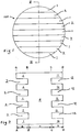
Fig 1 shows an end elevation of a first quarter wave plate which embodies the invention when it is modified to include the continuous region shown inFigures 5 to 7 . -
Fig 2 shows a sectioned view offigure 1 along the line II-II; and -
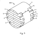
Fig 3 shows an isometric view of the first quarter wave plate; -
Fig 4 shows an embodiment of the invention; -
Fig 5 shows an isometric view of one of the plates offig 4 ; -
Fig 6 shows an end deviation offig 5 ; and -
Fig 7 shows a sectioned view offig 6 along the line VII-V11. - Before describing the embodiments it should be made clear for the avoidance of doubt that, when referring to the relative dielectric constant of a material, "soft" refers to materials having a low dielectric constant, and "hard" refers to materials having a high dielectric constant. For the purposes of this specification, a soft material is one having a relative constant less than 5 and a hard material is one having a relative dielectric constant greater than 5. The terms "hard" and "soft" in this context do not necessarily mean that the materials in question are also hard or soft in a physical sense.
- Referring to
figs 1, 2 and3 of the drawings, aquarter wave plate 100 is constructed of a "soft" isotropic dielectric comprising a cross-linked styrene copolymer having a relative dielectric constant of about 2.5 at its design frequency. The plate is in the general form
of a right circular cylinder having a first plurality ofgrooves 2 formed in one end face leaving a first plurality of lands 1 therebetween, and a second plurality ofgrooves 12 formed in the opposite face having a second plurality of lands 11 therebetween, the first plurality ofgrooves 2 being parallel with the second plurality ofgrooves 12. - The first plurality of lands 1 and
grooves 2 constitute a first region delimited by lines A-A and B-B and having an axial length a equal to the depth of thegrooves 2. The second plurality of lands 11 andgrooves 12 constitute a second region delimited by lines C-C and D-D and having an axial length b equal to the depth of thegrooves 12. - The third region delimited by lines B-B and C-C constitutes a third region having an axial length c.
- The sum of axial lengths a and b is such that a wave traversing the distance a + b through the isotropic dielectric exhibits a quarter wave length phase shift with respect to a wave travelling the distance a + b through the medium filling the grooves. In the present embodiment this medium is air. In the present example the wave plate is completely reflection symmetric about its centre and the first region is identical with the second region. Thus the impedance of the first region at plane B-B is the same as the impedance of the second region at plate C-C. The length c of the third region is nominally one half wavelength of the design frequency. A half wavelength structure has the property that, whatever impedance is presented to one end, that impedance appears unchanged at the other end and thus the half wave central region effectively couples B-B directly to C-C.
- As the impedance at plane B-B is the same as the impedance at plane C-C, theoretically a perfect impedance match results, with no loss by reflection at surfaces B-B or C-C. By designing the input impedances of the first and second structures for minimum reflection loss at surfaces A-A or D-D, the loss by reflection of energy traversing the quarter wave plate can be minimised. The reflectivity for input waves whose E-vector is parallel to the grooves is preferably as close as possible to the reflectivity for input waves whose E-vector is orthogonal to the grooves. This preserves the amplitude relationship between orthogonal components. By allowing plane polarised radiation to impinge on the structure with its E-vector at 45 degrees to the axis of the grooves, the two orthogonal components will emerge with equal amplitudes, thereby ensuring that circular (not elliptical) polarised radiation results.
- Details of the procedure for determining the dimensions of the first and second sections will now be given.
- A known method of providing a substantially reflection-free transformation between media having different characteristic impedances Z1, Z2 involves the provision between the media of a quarter-wavelength section (i.e. a section having a length of one quarter wavelength at the design frequency) having a characteristic impedance Z3 which is the square root of the product of the two impedances, i.e.

- The publication "The Design Of Quarter Wave Matching Layers For Dielectric Surfaces" by R.E. Collin and J. Brown, (Proc, IEE Part C Vol 103, 1956, pp 153-158), teaches the design of structures having an electrical length of one quarter wavelength for providing a good impedance match between free space and a dielectric by providing slots in the surface of the dielectric at its interface with free space. The design techniques described in this prior art to construct impedance transformers, can be used to design the radial dimensions of the grooves of quarter wave plates in accordance with the present invention.
- The first step is to determine the dimensions of the grooves which would be necessary to construct a quarter wave matching layer between free space and the dielectric material of which the quarter wave plate is to be constructed, using the design criteria given in the Collin et al paper supra.
- The next step is to determine the axial groove length l which would be necessary to produce a quarter wavelength phase shift between a wave travelling in the dielectric and a wave travelling the same distance in free space. Halving the length thus determined gives the respective axial depths a, b of the slots, i.e. a=b=l/2. Dimension c is nominally the length of one half wavelength of the design frequency in the dielectric medium. Applicants found that the making dimension c exactly equal to one half wavelength did not produce the minimum reflection in practice. Applicants found that varying dimension c of the third section allowed a fine tuning of the reflection coefficient of the quarter wave plate. An estimation of the exact dimensions can be made by computer modelling, or empirically determined by simply making a number of structures which are identical in all respects other than dimension c, and determining by actual tests the dimension c giving the best reflection coefficient.
- The resulting structure may be considered to have an impedance at plane A-A and D-D providing a good match to free space, and impedances at planes B-B and C-C which are a function of the lengths a and b. While these latter impedances will in general not be such as to provide a good impedance match to the dielectric, this does not matter as the half-wavelength third section of length c effectively brings plane B-B coincident with plane C-C, thereby providing an impedance match between the first and second sections. Varying length c allows fine tuning of the reflections coefficients at planes A-A and D-D. The sum of lengths a and b is such as to provide the necessary anisotropic birefringent dielectric properties necessary for the structure to behave as a quarter wave plate.
- Additional degrees of design freedom can be obtained by using a compound arrangement consisting of two or more discrete plates, the plates being such that a total differential phase shift of one quarter wavelength (or an odd integer multiple thereof) is imported to orthogonal components of a wave in its passage through the plates. The distance between the plates and the nature of the dielectric therebetween provides additional degrees of design freedom.
-
Figure 4 shows schematically aquarter wave plate 400 which consists of first and second eighth-wave plates gap 60. In the present embodiment the gap consists of air, and the same medium (air) is present on both sides of the quarter wave plate. This permits the use of a symmetrical arrangement in which the eighth-wave plates wave plat Figures 1 to 3 in that each face is provided with a plurality of parallel grooves: however whereas inFigures 1 to 3 the groove depth was such as to produce a one-eighth differential phase shift in each of regions a and b, in the present embodiment the depth is such as to produce a one-sixteenth wavelength differential phase shift in each of regions a', b', b" and a". It will be seen that the total differential phase shift is four times one-sixteenth, i.e. one quarter wavelength. As inFigures 1 to 3 the axial dimensions c', c" ofregions gap 60 can be varied to optimise parameters such as the reflection coefficient. - One of the eighth-
wave plates 40 will now be described with reference tofigures 5 ,6 and 7 . As noted above, theother plate 50 is identical.Plate 50 is of generally right circular cylindrical form. Each end of the cylinder has a plurality of spaced-apartparallel grooves 42, 42' formed in the ends thereof, the grooves being defined bylands 41, 41'. In the present embodiment theplate 40 is produced by moulding and to provide mechanical strength thegrooves 42, 42' do not extend completely across the end faces. Instead a continuous circumferentialannular region 43, 43' is left at the perimeter of each end face which supports and protects the radial ends of thelands 41, 41'. The grooved regions are sufficiently large that they intercept all the electromagnetic radiation whose polarisation is to be modified. Thus the presence of the circumferentialannular regions 43, 43' have no effect on the operation of the plate in use. Because this embodiment is designed to be manufactured by moulding, the lateral walls of thegrooves 42, 42' are not exactly perpendicular to the end faces of the cylinder, but are slightly tapered to facilitate release from the mould in which the plate is manufactured. This taper is shown in somewhat exaggerated from in the schematic view offig 7 for clarity. - In a modification, not shown, the medium in the
intermediate space 60 is not air but comprises a material of a dielectric constant other than unity. This material may be the same as the material filling the grooves in the facing regions b', b". - In a further modification, not shown, a quarter wave plate in accordance with the invention may consist of more than two plates. The differential phase shift contributed by each plate is such that the total differential phase shift is an odd integer multiple of one quarter wavelength. Thus a three plate arrangement could have three identical plates, each producing a one-twelfth wavelength phase shift, or one plate having a one-eighth phase shift in conjunction with two plates each having a one-sixteenth phase shift, or any other combination producing a total differential phase shift of one quarter wavelength. While more complex than a two plate arrangement, the extra gaps between plates provide extra degrees of design freedom.
- While the
grooves Figures 1 to 3 are shown as extending entirely across the structure, this is not necessary. It is only necessary for the grooves to extend across that part of the structure through which electromagnetic radiation has to pass. Thus the periphery of each end face may be continuous, providing mechanical support for the ends of lands 1, 11 as in showin inFigures 5 and6 . When modified to include the continuous region, the wave plate shown inFigures 1 to 3 forms an embodiment of the invention. - It is not necessary for the total phase shift provided by the grooved sections to be one quarter wavelength. Any odd integer multiple of quarter wavelengths will suffice.
- It is not necessary for the intermediate sections to be one half-wavelength (nominal). Any integer multiple of half wavelengths will suffice.
- While the described embodiments employs a "soft" substrate having a low dielectric constant, material of any dielectric constant may be employed
- While the described embodiments provide quarter wave plates for use in air, the invention can also be performed where the dielectric interfaces with a medium other than air and having a relative dielectric constant other than unity, the relevant dimensions being changed according to the dielectric constant of the medium as to give the necessary differential phase shift.
- While the described embodiments are quarter wave plates in which the same medium is present at both axial ends, the invention can also be performed where different media are present at opposite ends, eg air at one end and oil at the other end. The dimensions of the slots at each end are then of different design so as to provide impedance matching
between the respective media and the dielectric. Thus in an embodiment physically consisting of a single plate, the sum of lengths a and b is such to provide the necessary phase shift. It is to be noted that the paths to be compared now comprise on the one hand a path via the dielectric, and on the other hand a path partly in one medium and partly in the other medium. The actual lengths of a and b are chosen so as to present the same impedances at intermediate surfaces B-B and C-C, fine tuning being effected by varying dimension c as before. Similar considerations apply, mutatis mutandis, to arrangements physically consisting of more than one plate. - The grooves may be provided by any convenient method appropriate to the dielectric material used, eg milling, casting or grinding.
- While the embodiment depicts a circular cylindrical structure, the structure may be any shape appropriate to the application or structure in which the device is to be employed.
Claims (8)
- A quarter wave plate (100; 400) comprising at least one body of dielectric material, the or each said body having first and second end faces on opposite sides thereof; the or each body comprisinga first portion (a; a', a") comprising a first number of parallel grooves (2; 42) extending inwardly of said first end face;a second portion (b; b', b") comprising a second number of parallel grooves (12; 42') extending inwardly of said second end face; the second number being identical to the first number and each groove (2, 42) of the first portion (a; a', a") being aligned with a corresponding groove (12, 42') of the second portion (b; b', b"); anda third portion (c; c', c") defined between the first and second portions; the respective depths of the first (2; 42) and second grooves (12; 42') being such that a phase difference of an odd integer multiple of quarter wavelengths is produced between first and second orthogonal components of an electromagnetic wave traversing the plate (100; 400), the first component having its E-vector parallel to the grooves (2, 12; 42, 42'), the second component having its E-vector perpendicular to the grooves (2, 12; 42, 42');characterised in thatthe dielectric material has a relative dielectric constant of less than 5; andthe length of the third portion (c; c', c") is not exactly an integer number of half wavelengths but varies from an integer number of half wavelengths by an amount selected to minimise the reflection coefficient at the first and second end faces.
- A quarter wave plate as claimed in claim 1 in which the dielectric comprises a cross-linked styrene copolymer.
- A quarter wave plate as claimed in any preceding claim wherein the depth of the first grooves (2; 42) is equal to the depth of the second grooves (12; 42').
- A quarter wave plate as claimed in claim 3, in which the plate (100) comprises a single said body and wherein the depth of the grooves (2, 12) is such as to produce a respective phase difference of one eighth of a wavelength between said first and second orthogonal components when the wave traverses the first (a) and the second (b) portions respectively.
- A quarter wave plate as claimed in claim 3, in which the plate comprises two said bodies (40, 50), wherein the depth of the grooves (42, 42') is such as to produce a phase difference of one sixteenth of a wavelength between said first and second orthogonal components when the wave traverses each first (a', a") or second (b', b") portion.
- A quarter wave plate as claimed in claim 5, in which the two bodies (40, 50) are separated by an air gap.
- A quarter wave plate as claimed in any preceding claim being of cylindrical structure.
- A quarter wave plate as claimed in any preceding claim in which the or each body comprises a continuous region which defines the perimeter of each end face.
Applications Claiming Priority (2)
| Application Number | Priority Date | Filing Date | Title |
|---|---|---|---|
| GB9900763A GB2345797B (en) | 1999-01-15 | 1999-01-15 | Quarter wave plate |
| EP99310081A EP1022800A3 (en) | 1999-01-15 | 1999-12-15 | Quarter wave plate |
Related Parent Applications (1)
| Application Number | Title | Priority Date | Filing Date |
|---|---|---|---|
| EP99310081A Division EP1022800A3 (en) | 1999-01-15 | 1999-12-15 | Quarter wave plate |
Publications (2)
| Publication Number | Publication Date |
|---|---|
| EP1912276A1 EP1912276A1 (en) | 2008-04-16 |
| EP1912276B1 true EP1912276B1 (en) | 2018-11-07 |
Family
ID=10845928
Family Applications (2)
| Application Number | Title | Priority Date | Filing Date |
|---|---|---|---|
| EP07075901.4A Expired - Lifetime EP1912276B1 (en) | 1999-01-15 | 1999-12-15 | Quarter wave plate |
| EP99310081A Ceased EP1022800A3 (en) | 1999-01-15 | 1999-12-15 | Quarter wave plate |
Family Applications After (1)
| Application Number | Title | Priority Date | Filing Date |
|---|---|---|---|
| EP99310081A Ceased EP1022800A3 (en) | 1999-01-15 | 1999-12-15 | Quarter wave plate |
Country Status (4)
| Country | Link |
|---|---|
| US (2) | US6356164B1 (en) |
| EP (2) | EP1912276B1 (en) |
| ES (1) | ES2701155T3 (en) |
| GB (1) | GB2345797B (en) |
Families Citing this family (6)
| Publication number | Priority date | Publication date | Assignee | Title |
|---|---|---|---|---|
| ATE279492T1 (en) * | 2000-03-02 | 2004-10-15 | Merck Patent Gmbh | MULTI-LAYER REFLECTIVE FILM OR PIGMENT HAVING VIEWING ANGLE DEPENDENT REFLECTIVE PROPERTIES |
| US7146084B2 (en) * | 2003-06-16 | 2006-12-05 | Cmc Electronics, Inc. | Fiber optic light source for display devices |
| US9559397B2 (en) * | 2014-04-09 | 2017-01-31 | The Boeing Company | Circular dielectric polarizer having a dielectric slab sandwiched by dielectric core portions having air cutouts therein |
| US10547117B1 (en) * | 2017-12-05 | 2020-01-28 | Unites States Of America As Represented By The Secretary Of The Air Force | Millimeter wave, wideband, wide scan phased array architecture for radiating circular polarization at high power levels |
| US10840573B2 (en) | 2017-12-05 | 2020-11-17 | The United States Of America, As Represented By The Secretary Of The Air Force | Linear-to-circular polarizers using cascaded sheet impedances and cascaded waveplates |
| CN109921194B (en) * | 2019-01-22 | 2021-05-18 | 重庆邮电大学 | Broadband terahertz quarter-wave plate based on asymmetric cracks |
Citations (1)
| Publication number | Priority date | Publication date | Assignee | Title |
|---|---|---|---|---|
| EP0569015A2 (en) * | 1992-05-07 | 1993-11-10 | Hughes Aircraft Company | Molded waveguide components |
Family Cites Families (6)
| Publication number | Priority date | Publication date | Assignee | Title |
|---|---|---|---|---|
| DE1081075B (en) * | 1956-04-24 | 1960-05-05 | Marie G R P | Dielectric lens |
| JPS5329046A (en) * | 1976-08-30 | 1978-03-17 | Nippon Telegr & Teleph Corp <Ntt> | Wide band circular polarized wave generator |
| JPS53135550A (en) * | 1977-05-02 | 1978-11-27 | Nippon Telegr & Teleph Corp <Ntt> | Polarized wave compensation type hybrid |
| US4568943A (en) * | 1983-05-31 | 1986-02-04 | Rca Corporation | Antenna feed with mode conversion and polarization conversion means |
| US4551692A (en) * | 1984-03-28 | 1985-11-05 | United Technologies Corporation | Monolithic polarizer grating |
| JPH02260901A (en) * | 1989-03-31 | 1990-10-23 | Kyocera Corp | Circularly polarized wave generator |
-
1999
- 1999-01-15 GB GB9900763A patent/GB2345797B/en not_active Expired - Lifetime
- 1999-12-15 EP EP07075901.4A patent/EP1912276B1/en not_active Expired - Lifetime
- 1999-12-15 ES ES07075901T patent/ES2701155T3/en not_active Expired - Lifetime
- 1999-12-15 EP EP99310081A patent/EP1022800A3/en not_active Ceased
-
2000
- 2000-01-12 US US09/481,666 patent/US6356164B1/en not_active Ceased
-
2013
- 2013-03-18 US US13/846,709 patent/USRE45519E1/en not_active Expired - Lifetime
Patent Citations (1)
| Publication number | Priority date | Publication date | Assignee | Title |
|---|---|---|---|---|
| EP0569015A2 (en) * | 1992-05-07 | 1993-11-10 | Hughes Aircraft Company | Molded waveguide components |
Also Published As
| Publication number | Publication date |
|---|---|
| GB2345797A (en) | 2000-07-19 |
| ES2701155T3 (en) | 2019-02-21 |
| EP1022800A2 (en) | 2000-07-26 |
| EP1912276A1 (en) | 2008-04-16 |
| US6356164B1 (en) | 2002-03-12 |
| USRE45519E1 (en) | 2015-05-19 |
| EP1022800A3 (en) | 2001-11-14 |
| GB9900763D0 (en) | 1999-03-03 |
| GB2345797B (en) | 2003-09-03 |
Similar Documents
| Publication | Publication Date | Title |
|---|---|---|
| USRE45519E1 (en) | Quarter wave plate polarizer with two phase-shifting portions | |
| Shen et al. | Synthetic exceptional points and unidirectional zero reflection in non-Hermitian acoustic systems | |
| US5010348A (en) | Device for exciting a waveguide with circular polarization from a plane antenna | |
| US20200365962A1 (en) | A transition arrangement comprising a waveguide twist, a waveguide structure comprising a number of waveguide twists and a rotary joint | |
| US4126835A (en) | Balanced phase septum polarizer | |
| JPH03145305A (en) | Micro strip antenna | |
| US9419322B2 (en) | Compact waveguide circular polarizer | |
| Nesic et al. | Bandstop microstrip PBG filter with sinusoidal variation of the characteristic impedance and without etching in the ground plane | |
| US8693828B2 (en) | Photonic choke-joints for dual polarization waveguides | |
| US9391374B2 (en) | Reciprocal circular polarization selective surfaces and elements thereof | |
| EP3333968B1 (en) | A directional coupler and a method of manufacturing thereof | |
| US4725795A (en) | Corrugated ridge waveguide phase shifting structure | |
| Dey et al. | Single/dual broad band reflective type linear cross polarization converters with slotted meander lines for X/Ku/K band applications | |
| US4523160A (en) | Waveguide polarizer having conductive and dielectric loading slabs to alter polarization of waves | |
| EP0357085B1 (en) | A coaxial-waveguide phase shifter | |
| CN100395916C (en) | Frequency selective surface based on substrate-integrated waveguide technology | |
| CN115425429A (en) | Single-layer omnidirectional circularly polarized transmission array antenna based on polarization conversion super surface | |
| Oswald et al. | Dual-band infrared metallodielectric photonic crystal filters | |
| Shenouda et al. | Etched-silicon micromachined W-band waveguides and horn antennas | |
| US6465930B1 (en) | Transducer with surface acoustic waves with low gap | |
| Kirilenko et al. | Topology of a Planar-chiral Iris as a Factor in Controlling the" Optical Activity" of a Bilayer Object | |
| CN210379358U (en) | A High Power Capacity Slotted Circular Waveguide Circular Polarizer | |
| CN205911398U (en) | Coaxial Waveguide Two-Dimensional Electromagnetic Bandgap Structure | |
| Nesti et al. | Design of two Ku-band orthomode transducers for radio astronomy applications | |
| CN115332817A (en) | Broadband terahertz partition plate circular polarizer without resonance |
Legal Events
| Date | Code | Title | Description |
|---|---|---|---|
| PUAI | Public reference made under article 153(3) epc to a published international application that has entered the european phase |
Free format text: ORIGINAL CODE: 0009012 |
|
| AC | Divisional application: reference to earlier application |
Ref document number: 1022800 Country of ref document: EP Kind code of ref document: P |
|
| AK | Designated contracting states |
Kind code of ref document: A1 Designated state(s): AT BE CH CY DE DK ES FI FR GB GR IE IT LI LU MC NL PT SE |
|
| RIN1 | Information on inventor provided before grant (corrected) |
Inventor name: ROWATT, CHARLES ANTHONY |
|
| 17P | Request for examination filed |
Effective date: 20080512 |
|
| 17Q | First examination report despatched |
Effective date: 20080613 |
|
| AKX | Designation fees paid |
Designated state(s): AT BE CH CY DE DK ES FI FR GB GR IE IT LI LU MC NL PT SE |
|
| RAP1 | Party data changed (applicant data changed or rights of an application transferred) |
Owner name: BAE SYSTEMS INTEGRATED SYSTEM TECHNOLOGIES LIMITED |
|
| RAP1 | Party data changed (applicant data changed or rights of an application transferred) |
Owner name: MBDA UK LIMITED |
|
| GRAJ | Information related to disapproval of communication of intention to grant by the applicant or resumption of examination proceedings by the epo deleted |
Free format text: ORIGINAL CODE: EPIDOSDIGR1 |
|
| GRAP | Despatch of communication of intention to grant a patent |
Free format text: ORIGINAL CODE: EPIDOSNIGR1 |
|
| APBK | Appeal reference recorded |
Free format text: ORIGINAL CODE: EPIDOSNREFNE |
|
| APBN | Date of receipt of notice of appeal recorded |
Free format text: ORIGINAL CODE: EPIDOSNNOA2E |
|
| APBR | Date of receipt of statement of grounds of appeal recorded |
Free format text: ORIGINAL CODE: EPIDOSNNOA3E |
|
| APAF | Appeal reference modified |
Free format text: ORIGINAL CODE: EPIDOSCREFNE |
|
| APBT | Appeal procedure closed |
Free format text: ORIGINAL CODE: EPIDOSNNOA9E |
|
| GRAP | Despatch of communication of intention to grant a patent |
Free format text: ORIGINAL CODE: EPIDOSNIGR1 |
|
| INTG | Intention to grant announced |
Effective date: 20180608 |
|
| GRAS | Grant fee paid |
Free format text: ORIGINAL CODE: EPIDOSNIGR3 |
|
| GRAA | (expected) grant |
Free format text: ORIGINAL CODE: 0009210 |
|
| AC | Divisional application: reference to earlier application |
Ref document number: 1022800 Country of ref document: EP Kind code of ref document: P |
|
| AK | Designated contracting states |
Kind code of ref document: B1 Designated state(s): AT BE CH CY DE DK ES FI FR GB GR IE IT LI LU MC NL PT SE |
|
| REG | Reference to a national code |
Ref country code: GB Ref legal event code: FG4D |
|
| REG | Reference to a national code |
Ref country code: CH Ref legal event code: EP Ref country code: AT Ref legal event code: REF Ref document number: 1063191 Country of ref document: AT Kind code of ref document: T Effective date: 20181115 |
|
| REG | Reference to a national code |
Ref country code: IE Ref legal event code: FG4D |
|
| REG | Reference to a national code |
Ref country code: DE Ref legal event code: R096 Ref document number: 69945899 Country of ref document: DE |
|
| PGFP | Annual fee paid to national office [announced via postgrant information from national office to epo] |
Ref country code: FI Payment date: 20181219 Year of fee payment: 20 |
|
| REG | Reference to a national code |
Ref country code: ES Ref legal event code: FG2A Ref document number: 2701155 Country of ref document: ES Kind code of ref document: T3 Effective date: 20190221 |
|
| REG | Reference to a national code |
Ref country code: SE Ref legal event code: TRGR |
|
| PGFP | Annual fee paid to national office [announced via postgrant information from national office to epo] |
Ref country code: GB Payment date: 20181221 Year of fee payment: 20 Ref country code: FR Payment date: 20181231 Year of fee payment: 20 Ref country code: BE Payment date: 20181221 Year of fee payment: 20 |
|
| REG | Reference to a national code |
Ref country code: NL Ref legal event code: MP Effective date: 20181107 |
|
| REG | Reference to a national code |
Ref country code: AT Ref legal event code: MK05 Ref document number: 1063191 Country of ref document: AT Kind code of ref document: T Effective date: 20181107 |
|
| PG25 | Lapsed in a contracting state [announced via postgrant information from national office to epo] |
Ref country code: AT Free format text: LAPSE BECAUSE OF FAILURE TO SUBMIT A TRANSLATION OF THE DESCRIPTION OR TO PAY THE FEE WITHIN THE PRESCRIBED TIME-LIMIT Effective date: 20181107 |
|
| PGFP | Annual fee paid to national office [announced via postgrant information from national office to epo] |
Ref country code: IT Payment date: 20181220 Year of fee payment: 20 Ref country code: ES Payment date: 20190131 Year of fee payment: 20 Ref country code: DE Payment date: 20190228 Year of fee payment: 20 |
|
| PG25 | Lapsed in a contracting state [announced via postgrant information from national office to epo] |
Ref country code: NL Free format text: LAPSE BECAUSE OF FAILURE TO SUBMIT A TRANSLATION OF THE DESCRIPTION OR TO PAY THE FEE WITHIN THE PRESCRIBED TIME-LIMIT Effective date: 20181107 Ref country code: GR Free format text: LAPSE BECAUSE OF FAILURE TO SUBMIT A TRANSLATION OF THE DESCRIPTION OR TO PAY THE FEE WITHIN THE PRESCRIBED TIME-LIMIT Effective date: 20190208 Ref country code: PT Free format text: LAPSE BECAUSE OF FAILURE TO SUBMIT A TRANSLATION OF THE DESCRIPTION OR TO PAY THE FEE WITHIN THE PRESCRIBED TIME-LIMIT Effective date: 20190307 |
|
| PG25 | Lapsed in a contracting state [announced via postgrant information from national office to epo] |
Ref country code: DK Free format text: LAPSE BECAUSE OF FAILURE TO SUBMIT A TRANSLATION OF THE DESCRIPTION OR TO PAY THE FEE WITHIN THE PRESCRIBED TIME-LIMIT Effective date: 20181107 |
|
| REG | Reference to a national code |
Ref country code: CH Ref legal event code: PL |
|
| REG | Reference to a national code |
Ref country code: DE Ref legal event code: R097 Ref document number: 69945899 Country of ref document: DE |
|
| PG25 | Lapsed in a contracting state [announced via postgrant information from national office to epo] |
Ref country code: MC Free format text: LAPSE BECAUSE OF FAILURE TO SUBMIT A TRANSLATION OF THE DESCRIPTION OR TO PAY THE FEE WITHIN THE PRESCRIBED TIME-LIMIT Effective date: 20181107 Ref country code: LU Free format text: LAPSE BECAUSE OF NON-PAYMENT OF DUE FEES Effective date: 20181215 |
|
| PGFP | Annual fee paid to national office [announced via postgrant information from national office to epo] |
Ref country code: SE Payment date: 20181228 Year of fee payment: 20 |
|
| PLBE | No opposition filed within time limit |
Free format text: ORIGINAL CODE: 0009261 |
|
| STAA | Information on the status of an ep patent application or granted ep patent |
Free format text: STATUS: NO OPPOSITION FILED WITHIN TIME LIMIT |
|
| REG | Reference to a national code |
Ref country code: IE Ref legal event code: MM4A |
|
| 26N | No opposition filed |
Effective date: 20190808 |
|
| PG25 | Lapsed in a contracting state [announced via postgrant information from national office to epo] |
Ref country code: IE Free format text: LAPSE BECAUSE OF NON-PAYMENT OF DUE FEES Effective date: 20181215 |
|
| REG | Reference to a national code |
Ref country code: DE Ref legal event code: R071 Ref document number: 69945899 Country of ref document: DE |
|
| PG25 | Lapsed in a contracting state [announced via postgrant information from national office to epo] |
Ref country code: CH Free format text: LAPSE BECAUSE OF NON-PAYMENT OF DUE FEES Effective date: 20181231 Ref country code: LI Free format text: LAPSE BECAUSE OF NON-PAYMENT OF DUE FEES Effective date: 20181231 |
|
| REG | Reference to a national code |
Ref country code: GB Ref legal event code: PE20 Expiry date: 20191214 |
|
| REG | Reference to a national code |
Ref country code: FI Ref legal event code: MAE |
|
| REG | Reference to a national code |
Ref country code: BE Ref legal event code: MK Effective date: 20191215 |
|
| REG | Reference to a national code |
Ref country code: SE Ref legal event code: EUG |
|
| PG25 | Lapsed in a contracting state [announced via postgrant information from national office to epo] |
Ref country code: GB Free format text: LAPSE BECAUSE OF EXPIRATION OF PROTECTION Effective date: 20191214 |
|
| PG25 | Lapsed in a contracting state [announced via postgrant information from national office to epo] |
Ref country code: CY Free format text: LAPSE BECAUSE OF FAILURE TO SUBMIT A TRANSLATION OF THE DESCRIPTION OR TO PAY THE FEE WITHIN THE PRESCRIBED TIME-LIMIT Effective date: 20181107 |
|
| REG | Reference to a national code |
Ref country code: ES Ref legal event code: FD2A Effective date: 20200803 |
|
| PG25 | Lapsed in a contracting state [announced via postgrant information from national office to epo] |
Ref country code: ES Free format text: LAPSE BECAUSE OF EXPIRATION OF PROTECTION Effective date: 20191216 |