EP1912032A1 - Refrigeration appliance with a water dispenser - Google Patents
Refrigeration appliance with a water dispenser Download PDFInfo
- Publication number
- EP1912032A1 EP1912032A1 EP06122207A EP06122207A EP1912032A1 EP 1912032 A1 EP1912032 A1 EP 1912032A1 EP 06122207 A EP06122207 A EP 06122207A EP 06122207 A EP06122207 A EP 06122207A EP 1912032 A1 EP1912032 A1 EP 1912032A1
- Authority
- EP
- European Patent Office
- Prior art keywords
- water
- reservoir
- piping system
- refrigeration appliance
- dispenser
- Prior art date
- Legal status (The legal status is an assumption and is not a legal conclusion. Google has not performed a legal analysis and makes no representation as to the accuracy of the status listed.)
- Granted
Links
- XLYOFNOQVPJJNP-UHFFFAOYSA-N water Substances O XLYOFNOQVPJJNP-UHFFFAOYSA-N 0.000 title claims abstract description 104
- 238000005057 refrigeration Methods 0.000 title claims abstract description 10
- 238000001816 cooling Methods 0.000 claims description 6
- 230000003134 recirculating effect Effects 0.000 claims 3
- 238000000034 method Methods 0.000 claims 1
- 238000007710 freezing Methods 0.000 description 5
- 230000008014 freezing Effects 0.000 description 5
- 235000013361 beverage Nutrition 0.000 description 4
- 230000008901 benefit Effects 0.000 description 2
- 239000006260 foam Substances 0.000 description 2
- 239000011521 glass Substances 0.000 description 1
- 238000010438 heat treatment Methods 0.000 description 1
- 238000009413 insulation Methods 0.000 description 1
Images

Classifications
-
- F—MECHANICAL ENGINEERING; LIGHTING; HEATING; WEAPONS; BLASTING
- F25—REFRIGERATION OR COOLING; COMBINED HEATING AND REFRIGERATION SYSTEMS; HEAT PUMP SYSTEMS; MANUFACTURE OR STORAGE OF ICE; LIQUEFACTION SOLIDIFICATION OF GASES
- F25D—REFRIGERATORS; COLD ROOMS; ICE-BOXES; COOLING OR FREEZING APPARATUS NOT OTHERWISE PROVIDED FOR
- F25D23/00—General constructional features
- F25D23/12—Arrangements of compartments additional to cooling compartments; Combinations of refrigerators with other equipment, e.g. stove
- F25D23/126—Water cooler
-
- F—MECHANICAL ENGINEERING; LIGHTING; HEATING; WEAPONS; BLASTING
- F25—REFRIGERATION OR COOLING; COMBINED HEATING AND REFRIGERATION SYSTEMS; HEAT PUMP SYSTEMS; MANUFACTURE OR STORAGE OF ICE; LIQUEFACTION SOLIDIFICATION OF GASES
- F25D—REFRIGERATORS; COLD ROOMS; ICE-BOXES; COOLING OR FREEZING APPARATUS NOT OTHERWISE PROVIDED FOR
- F25D21/00—Defrosting; Preventing frosting; Removing condensed or defrost water
- F25D21/06—Removing frost
- F25D21/12—Removing frost by hot-fluid circulating system separate from the refrigerant system
-
- F—MECHANICAL ENGINEERING; LIGHTING; HEATING; WEAPONS; BLASTING
- F25—REFRIGERATION OR COOLING; COMBINED HEATING AND REFRIGERATION SYSTEMS; HEAT PUMP SYSTEMS; MANUFACTURE OR STORAGE OF ICE; LIQUEFACTION SOLIDIFICATION OF GASES
- F25D—REFRIGERATORS; COLD ROOMS; ICE-BOXES; COOLING OR FREEZING APPARATUS NOT OTHERWISE PROVIDED FOR
- F25D2400/00—General features of, or devices for refrigerators, cold rooms, ice-boxes, or for cooling or freezing apparatus not covered by any other subclass
- F25D2400/28—Quick cooling
Definitions
- the present invention relates to a refrigerator comprising at least a water reservoir, a piping system connecting the water reservoir to a dispenser and means for maintaining the water reservoir at a predetermined temperature.
- water we include also still or carbonated water and any kind of beverages, carbonated or not.
- Refrigerators with a beverage dispenser are well known in the art. Such dispensers are particularly but not exclusively used in the so-called side by side refrigerators in which a freezing chamber is provided side by side to a chilling chamber. Usually the dispenser for water and other beverages is placed in a case of the door of the freezing chamber, particularly because the dispenser is used also for dispensing ice cubes or crushed ice produced by an ice-maker inside the freezing chamber.
- the reservoir for cold water is usually placed in the chilling chamber and it is maintained at the same temperature of such compartment.
- the reservoir can be a predetermined length of rolled up tube placed in the chilling chamber. In this case the above mentioned means for maintaining the water in the reservoir at a predetermined temperature is the cooling system of the chilling chamber. If the reservoir is used for storing hot water, usually it is placed outside the refrigerator compartments, for instance in the base zone of the refrigerator where it is also possible to use the heat released from the condenser to preheat the incoming water.
- Standard refrigerators like the side by side model mentioned above have a pipe inside the foam insulation which connects an external water supplying source, such as a tap, to the reservoir, through the door and then to the dispenser area.
- Such pipe can have a total length of about two meters or more.
- An object of the present invention is to provide a refrigeration appliance of the type mentioned above which can dispense water at the desired temperature anytime, independently on the temperature of the water left in the piping system by previous dispensing.
- refrigeration appliance we mean not only refrigerators and freezers, but also beverage vending machines, or water coolers.
- a side by side refrigerator R presents a door D of the freezing chamber.
- a water and ice dispenser W is provided, which is fed by a water tap 1 through a filter F and through a water reservoir 5 which, in the example shown in figure 2, is contained in the cooling compartment at a predetermined cold temperature.
- a T-branch K composed by 2 electrovalves K1 and K2 respectively, for delivering water also to an icemaker M contained in the freezing chamber.
- filtered inlet water from tap 1 goes to the reservoir 5. From this latter a pipe goes through the door D and to the water dispenser W. Since the length of such pipe is not neglectable, the volume contained therein has a temperature which may be not the same of the water contained in the reservoir 5.
- the water circuit comprises a pipe 2 which goes through the door and then to the dispenser area through an electrovalve 6.
- the electrovalve 6 remains closed and water flow stops.
- the electronic control (not shown) which is provided with a predetermined simple algorithm opens an electrovalve 4 and switches on a pump 10 mounted on an auxiliary recirculation pipe 9.
- the electronic control runs this cycle automatically at selected time sequence to maintain the water into the pipe always at the correct temperature substantially identical to the temperature of water in the water reservoir 5.
- the pump 10 and the electrovalve 4 can be switched on only when the user acts on the paddle of the water dispenser W. In this case the electronic control waits few second before opening the electrovalve 6 so that the recirculation along the auxiliary pipe 9 can bring the temperature of water to the same level of the temperature of water inside the water reservoir 5.
- This system solves the problem of water not at the desired level (hot or cold) at first dispensing and also prevent a too long permanence of water inside the piping, which could cause health and safety problems.
- a second embodiment provides the same benefit to a refrigerator that has hot & cold water to be dispensed on the same dispenser W.
- filtered inlet water line 1 is connected to both line 11 and line 12, and to the hot & cold reservoirs respectively 5a and 5b.
- the electrovalve EV1 When the paddle on the dispenser W is released, the electrovalve EV1 remains closed and the electronic control which is provided with a predetermined algorithm opens the electrovalve EV2 so the water flows through the auxiliary line 9, and switches on the pump 10. The water flows then through the line 15 and the circuit opens an electrovalve EV5 located in the base zone of the refrigerator, so that water returns to the hot water reservoir 5a.
- the water flows is recirculated back to the reservoir 5a.
- the electronic control runs this cycle automatically at selected time sequence to maintain the water into the pipe always at the correct temperature, or, as in the first embodiment, it can run the recirculation only when the user pushes the paddle for dispensing hot water.
- the electrovalve EV1 When the paddle on the dispenser W is released, the electrovalve EV1 remains closed and the electronic control opens the electrovalve EV2 so that the water is recirculated through auxiliary line 9 and by means of the pump 10, through an open electrovalve EV6 to the cold water reservoir 5b.
- a third embodiment is focused also on fast water cooling.
- the components which are similar to those of figure 4 have the same reference numerals.
- the refrigerator evaporator is cold and the cold water reservoir takes time to cool down in order to provide cold water at desired temperature, because cold is provided by force air circulation.
- a water pipe 16 with a portion 17 thereof in contact with the evaporator - not shown - (banded around, attached similarly to the electrical wire of the defrost heater), is connected to the water pump 10 by an electrovalve EV8 and on the other side to the line 15.
- An electrovalve EV7 closes the auxiliary line 10 - EV7 - 15 when the water goes through the evaporator line.
- Fast cooling feature is provided by keeping close the valve EV7, running the water pump 10 and opening the valve EV8, so that the water flows through the water pipe 17 in contact with the evaporator and goes back to the cold reservoir 5b. This technical solution allows faster water cooling inside the reservoir 5b.
- This embodiment may also be used for a fast evaporator defrost.
- the refrigerator evaporator During normal operation mode the refrigerator evaporator is cold and when it is time to defrost it, the operation requires a long time and high heater power.
- the circuit of figure 5 reduces dramatically the defrost time by sending hot water contained into reservoir 5a through the line 16 to the water pipe 17, which is in contact with the evaporator, by running the water pump 10 and by opening an electrovalve EV8. In this case the electrovalve EV7 is closed too.
- An electronic control (not shown) manages those features accordingly to consumer water dispensing needs, and refrigerator operation mode.
- Check or one-way valves to reduce cost and complexity of the system can replace some electrovalves.
- the present invention is independent on the system used for heating the water in the hot water reservoir 5a.
- one paddle instead of using two paddles for hot and cold water dispensing respectively, one paddle only can be used as well in combination with a device (for instance a button) for selecting hot or cold water.
- a device for instance a button
Landscapes
- Engineering & Computer Science (AREA)
- Chemical & Material Sciences (AREA)
- Combustion & Propulsion (AREA)
- Physics & Mathematics (AREA)
- Mechanical Engineering (AREA)
- Thermal Sciences (AREA)
- General Engineering & Computer Science (AREA)
- Devices That Are Associated With Refrigeration Equipment (AREA)
- Devices For Dispensing Beverages (AREA)
- Sampling And Sample Adjustment (AREA)
- Treatment Of Water By Ion Exchange (AREA)
Abstract
Description
- The present invention relates to a refrigerator comprising at least a water reservoir, a piping system connecting the water reservoir to a dispenser and means for maintaining the water reservoir at a predetermined temperature. In the present description, with the term water we include also still or carbonated water and any kind of beverages, carbonated or not.
- Refrigerators with a beverage dispenser are well known in the art. Such dispensers are particularly but not exclusively used in the so-called side by side refrigerators in which a freezing chamber is provided side by side to a chilling chamber. Usually the dispenser for water and other beverages is placed in a case of the door of the freezing chamber, particularly because the dispenser is used also for dispensing ice cubes or crushed ice produced by an ice-maker inside the freezing chamber. The reservoir for cold water is usually placed in the chilling chamber and it is maintained at the same temperature of such compartment. The reservoir can be a predetermined length of rolled up tube placed in the chilling chamber. In this case the above mentioned means for maintaining the water in the reservoir at a predetermined temperature is the cooling system of the chilling chamber. If the reservoir is used for storing hot water, usually it is placed outside the refrigerator compartments, for instance in the base zone of the refrigerator where it is also possible to use the heat released from the condenser to preheat the incoming water.
- Standard refrigerators like the side by side model mentioned above have a pipe inside the foam insulation which connects an external water supplying source, such as a tap, to the reservoir, through the door and then to the dispenser area. Such pipe can have a total length of about two meters or more.
- When consumer pushes the paddle on the dispenser, the water that is driven by the water pressure of the main comes out; when the paddle is released, the water flow stops.
- At this time the cold (or hot) water inside this pipe start to become warm (or cold), because of ambient temperature influence. So the first glass of water at the next dispensing is water at almost ambient temperature. Therefore the user is either provided with water not at the correct temperature or he/she can think the appliance is not working properly.
- An object of the present invention is to provide a refrigeration appliance of the type mentioned above which can dispense water at the desired temperature anytime, independently on the temperature of the water left in the piping system by previous dispensing. With the term "refrigeration appliance" we mean not only refrigerators and freezers, but also beverage vending machines, or water coolers.
- This object is achieved thanks to the features listed in the appended claims.
- Other features, aspects and advantages of the present invention will become more apparent from the following detailed description with reference to the accompanying drawings in which:
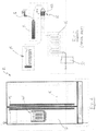
- figure 1 is a front view of a side by side refrigerator with a water dispenser;
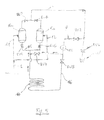
- figure 2 is a schematic view of the cold-water dispensing system of a refrigerator according to prior art;
- figure 3 is a schematic view of the cold or hot water dispensing system of a refrigerator according to a first embodiment of the invention;
- figure 4 is a schematic view of the cold and hot water dispensing system of a refrigerator according to a second embodiment of the invention; and
- figure 5 is a schematic view of a water dispensing system according to a third embodiment of the invention.
- With reference to figures 1 and 2, a side by side refrigerator R presents a door D of the freezing chamber. In the door D a water and ice dispenser W is provided, which is fed by a water tap 1 through a filter F and through a
water reservoir 5 which, in the example shown in figure 2, is contained in the cooling compartment at a predetermined cold temperature. Between the filter F and thewater reservoir 5 there is provided a T-branch K composed by 2 electrovalves K1 and K2 respectively, for delivering water also to an icemaker M contained in the freezing chamber. - During a normal operation mode in a refrigerator according to prior art (figure 2), filtered inlet water from tap 1 goes to the
reservoir 5. From this latter a pipe goes through the door D and to the water dispenser W. Since the length of such pipe is not neglectable, the volume contained therein has a temperature which may be not the same of the water contained in thereservoir 5. - According to a first embodiment of the present invention shown in figure 3, the water circuit comprises a
pipe 2 which goes through the door and then to the dispenser area through an electrovalve 6. When the paddle on the dispenser is released, the electrovalve 6 remains closed and water flow stops. - Whenever is needed, either after every dispensing, or after a predetermined fixed time, the electronic control (not shown) which is provided with a predetermined simple algorithm opens an
electrovalve 4 and switches on apump 10 mounted on an auxiliary recirculation pipe 9. In this case the water flows through the path 2-4-9-5 and back to the reservoir. The electronic control runs this cycle automatically at selected time sequence to maintain the water into the pipe always at the correct temperature substantially identical to the temperature of water in thewater reservoir 5. As an alternative, thepump 10 and theelectrovalve 4 can be switched on only when the user acts on the paddle of the water dispenser W. In this case the electronic control waits few second before opening the electrovalve 6 so that the recirculation along the auxiliary pipe 9 can bring the temperature of water to the same level of the temperature of water inside thewater reservoir 5. - This system solves the problem of water not at the desired level (hot or cold) at first dispensing and also prevent a too long permanence of water inside the piping, which could cause health and safety problems.
- With reference to figure 4, a second embodiment provides the same benefit to a refrigerator that has hot & cold water to be dispensed on the same dispenser W.
- During normal operation mode, filtered inlet water line 1 is connected to both line 11 and
line 12, and to the hot & cold reservoirs respectively 5a and 5b. - When the paddle for hot water is pushed, hot water goes from the hot reservoir 5a through the open electrovalve EV3 located in the base zone of the refrigerator and then, by means of the
water line 2 which is inside the foam door, water is delivered to the dispenser W by an open electrovalve EV1. - When the paddle on the dispenser W is released, the electrovalve EV1 remains closed and the electronic control which is provided with a predetermined algorithm opens the electrovalve EV2 so the water flows through the auxiliary line 9, and switches on the
pump 10. The water flows then through the line 15 and the circuit opens an electrovalve EV5 located in the base zone of the refrigerator, so that water returns to the hot water reservoir 5a. - In this case the water flows is recirculated back to the reservoir 5a. The electronic control runs this cycle automatically at selected time sequence to maintain the water into the pipe always at the correct temperature, or, as in the first embodiment, it can run the recirculation only when the user pushes the paddle for dispensing hot water.
- When the paddle for the cold water is pushed, cold water goes from the cold reservoir 5b through the open electrovalve EV4, and then by the
water line 2 to the dispenser W by the open electrovalve EV1. - When the paddle on the dispenser W is released, the electrovalve EV1 remains closed and the electronic control opens the electrovalve EV2 so that the water is recirculated through auxiliary line 9 and by means of the
pump 10, through an open electrovalve EV6 to the cold water reservoir 5b. - Also in this case the water flows back to the reservoir and the electronic control runs this cycle automatically at selected time sequence to maintain the water into the pipe always at the correct temperature.
- With reference to figure 5, a third embodiment is focused also on fast water cooling. In figure 5 the components which are similar to those of figure 4 have the same reference numerals. During normal operation mode the refrigerator evaporator is cold and the cold water reservoir takes time to cool down in order to provide cold water at desired temperature, because cold is provided by force air circulation.
- According to such third embodiment, a
water pipe 16, with a portion 17 thereof in contact with the evaporator - not shown - (banded around, attached similarly to the electrical wire of the defrost heater), is connected to thewater pump 10 by an electrovalve EV8 and on the other side to the line 15. An electrovalve EV7 closes the auxiliary line 10 - EV7 - 15 when the water goes through the evaporator line. - Fast cooling feature is provided by keeping close the valve EV7, running the
water pump 10 and opening the valve EV8, so that the water flows through the water pipe 17 in contact with the evaporator and goes back to the cold reservoir 5b. This technical solution allows faster water cooling inside the reservoir 5b. - This embodiment may also be used for a fast evaporator defrost. During normal operation mode the refrigerator evaporator is cold and when it is time to defrost it, the operation requires a long time and high heater power.
- The circuit of figure 5 reduces dramatically the defrost time by sending hot water contained into reservoir 5a through the
line 16 to the water pipe 17, which is in contact with the evaporator, by running thewater pump 10 and by opening an electrovalve EV8. In this case the electrovalve EV7 is closed too. - An electronic control (not shown) manages those features accordingly to consumer water dispensing needs, and refrigerator operation mode.
- Check or one-way valves to reduce cost and complexity of the system can replace some electrovalves. Moreover the present invention is independent on the system used for heating the water in the hot water reservoir 5a.
- Instead of using two paddles for hot and cold water dispensing respectively, one paddle only can be used as well in combination with a device (for instance a button) for selecting hot or cold water.
Claims (7)
- A refrigeration appliance comprising at least one water reservoir (5, 5a, 5b), a piping system (2, 6, EV1, EV3, EV4) connecting the water reservoir to a dispenser (W) and means for maintaining the water reservoir at a predetermined temperature, characterised in that it comprises an auxiliary piping system (4, 9, 10, EV2, EV5, EV6) for recirculating water to the water reservoir (5, 5a, 5b).
- A refrigeration appliance according to claim 1, characterised in that such auxiliary piping system includes a pump (10).
- A refrigeration appliance according to claim 2, in which the water dispenser (W) comprises a valve (6, EV1) for dispensing water on demand, characterised in that the auxiliary piping system comprises a second valve (4, EV2) which is connected to a central process unit for opening such valve and for switching on the pump (10) at predetermined time.
- A refrigeration appliance according to any of the preceding claims, characterised in that it comprises a second water reservoir, the first and second reservoirs (5a, 5b) containing water at different temperatures.
- A refrigeration appliance according to claim 4, characterised in that the auxiliary piping system comprises a pipe (9) connected to both the reservoirs (5a, 5b), valve means (EV5, EV6) being provided for recirculating water alternatively to one or the other reservoir (5a, 5b).
- A refrigeration appliance according to claim 2, characterised in that such auxiliary piping system comprises a branch (16, 17) in heat exchange relationship with an evaporator of the appliance in order to carry out a fast cooling of the recirculating water.
- A refrigerator according to claim 5 and 6, characterised in that in said branch (16, 17) of the auxiliary piping system hot water may be recirculated in order to carry out a quick defrost of the evaporator.
Priority Applications (6)
| Application Number | Priority Date | Filing Date | Title |
|---|---|---|---|
| AT06122207T ATE497137T1 (en) | 2006-10-12 | 2006-10-12 | COOLER WITH WATER DISPENSER |
| PL06122207T PL1912032T3 (en) | 2006-10-12 | 2006-10-12 | Refrigeration appliance with a water dispenser |
| DE602006019877T DE602006019877D1 (en) | 2006-10-12 | 2006-10-12 | Cooling unit with water dispenser |
| EP06122207A EP1912032B1 (en) | 2006-10-12 | 2006-10-12 | Refrigeration appliance with a water dispenser |
| ES06122207T ES2359152T3 (en) | 2006-10-12 | 2006-10-12 | REFRIGERATOR DEVICE WITH A WATER DISPENSER. |
| US11/869,998 US7814763B2 (en) | 2006-10-12 | 2007-10-10 | Refrigeration appliance with a water dispenser |
Applications Claiming Priority (1)
| Application Number | Priority Date | Filing Date | Title |
|---|---|---|---|
| EP06122207A EP1912032B1 (en) | 2006-10-12 | 2006-10-12 | Refrigeration appliance with a water dispenser |
Publications (2)
| Publication Number | Publication Date |
|---|---|
| EP1912032A1 true EP1912032A1 (en) | 2008-04-16 |
| EP1912032B1 EP1912032B1 (en) | 2011-01-26 |
Family
ID=38171236
Family Applications (1)
| Application Number | Title | Priority Date | Filing Date |
|---|---|---|---|
| EP06122207A Not-in-force EP1912032B1 (en) | 2006-10-12 | 2006-10-12 | Refrigeration appliance with a water dispenser |
Country Status (6)
| Country | Link |
|---|---|
| US (1) | US7814763B2 (en) |
| EP (1) | EP1912032B1 (en) |
| AT (1) | ATE497137T1 (en) |
| DE (1) | DE602006019877D1 (en) |
| ES (1) | ES2359152T3 (en) |
| PL (1) | PL1912032T3 (en) |
Cited By (1)
| Publication number | Priority date | Publication date | Assignee | Title |
|---|---|---|---|---|
| ITVA20100077A1 (en) * | 2010-10-14 | 2012-04-15 | Whirlpool Co | HOUSEHOLD APPLIANCES PROVIDED WITH REFRIGERATED WATER DISPENSER |
Families Citing this family (7)
| Publication number | Priority date | Publication date | Assignee | Title |
|---|---|---|---|---|
| BRPI0703807A2 (en) * | 2007-09-11 | 2009-04-28 | Whirlpool Sa | Water dispensing device at different temperatures |
| KR101419751B1 (en) * | 2012-10-18 | 2014-07-15 | 주식회사 위닉스 | Cooling apparatus |
| US8967432B2 (en) | 2013-03-15 | 2015-03-03 | Electrolux Home Products, Inc. | Refrigerator appliance with hot water dispenser |
| US9139415B2 (en) | 2013-03-15 | 2015-09-22 | Electrolux Home Products, Inc. | Refrigerator appliance with hot water dispenser |
| US9302897B2 (en) | 2014-08-06 | 2016-04-05 | Whirlpool Corporation | Methods and apparatus to chill dispensed beverages in refrigerators |
| US10697700B2 (en) * | 2018-01-17 | 2020-06-30 | Whirlpool Corporation | Refrigeration water dispensing system |
| US11814279B1 (en) | 2022-06-10 | 2023-11-14 | Quench Usa, Inc. | Water dispensing line recirculation |
Citations (4)
| Publication number | Priority date | Publication date | Assignee | Title |
|---|---|---|---|---|
| FR2511763A1 (en) * | 1981-08-20 | 1983-02-25 | Lanteri Guy | Rapid cooling system for drinks - uses serpentine pipe passing through ice box of refrigerator to cool liquid |
| US5502978A (en) | 1994-07-22 | 1996-04-02 | Big Iron Drilling Ltd. | Water cooling apparatus |
| WO2003033976A1 (en) * | 2001-10-16 | 2003-04-24 | Lg Electronics Inc. | Dispenser for refrigerator |
| EP1574797A2 (en) * | 2004-03-11 | 2005-09-14 | Norcold, Inc. | Chilled water dispensing arrangement for a refrigerator |
Family Cites Families (2)
| Publication number | Priority date | Publication date | Assignee | Title |
|---|---|---|---|---|
| ITTO20030747A1 (en) * | 2003-09-25 | 2005-03-26 | Elbi Int Spa | ELECTROVALVE DEVICE FOR DELIVERY FOR A REFRIGERATOR. |
| KR100658420B1 (en) * | 2004-12-22 | 2006-12-19 | 삼성광주전자 주식회사 | Refrigeration cycles and chillers |
-
2006
- 2006-10-12 AT AT06122207T patent/ATE497137T1/en not_active IP Right Cessation
- 2006-10-12 PL PL06122207T patent/PL1912032T3/en unknown
- 2006-10-12 ES ES06122207T patent/ES2359152T3/en active Active
- 2006-10-12 DE DE602006019877T patent/DE602006019877D1/en active Active
- 2006-10-12 EP EP06122207A patent/EP1912032B1/en not_active Not-in-force
-
2007
- 2007-10-10 US US11/869,998 patent/US7814763B2/en not_active Expired - Fee Related
Patent Citations (4)
| Publication number | Priority date | Publication date | Assignee | Title |
|---|---|---|---|---|
| FR2511763A1 (en) * | 1981-08-20 | 1983-02-25 | Lanteri Guy | Rapid cooling system for drinks - uses serpentine pipe passing through ice box of refrigerator to cool liquid |
| US5502978A (en) | 1994-07-22 | 1996-04-02 | Big Iron Drilling Ltd. | Water cooling apparatus |
| WO2003033976A1 (en) * | 2001-10-16 | 2003-04-24 | Lg Electronics Inc. | Dispenser for refrigerator |
| EP1574797A2 (en) * | 2004-03-11 | 2005-09-14 | Norcold, Inc. | Chilled water dispensing arrangement for a refrigerator |
Cited By (1)
| Publication number | Priority date | Publication date | Assignee | Title |
|---|---|---|---|---|
| ITVA20100077A1 (en) * | 2010-10-14 | 2012-04-15 | Whirlpool Co | HOUSEHOLD APPLIANCES PROVIDED WITH REFRIGERATED WATER DISPENSER |
Also Published As
| Publication number | Publication date |
|---|---|
| EP1912032B1 (en) | 2011-01-26 |
| ES2359152T3 (en) | 2011-05-18 |
| US7814763B2 (en) | 2010-10-19 |
| US20080087036A1 (en) | 2008-04-17 |
| DE602006019877D1 (en) | 2011-03-10 |
| ATE497137T1 (en) | 2011-02-15 |
| PL1912032T3 (en) | 2011-07-29 |
Similar Documents
| Publication | Publication Date | Title |
|---|---|---|
| US7814763B2 (en) | Refrigeration appliance with a water dispenser | |
| US5564601A (en) | Beverage dispensing machine with improved liquid chiller | |
| JP5248190B2 (en) | Beverage dispenser | |
| US9568240B2 (en) | Refrigerator appliance with hot water dispenser | |
| US9791198B2 (en) | Refrigerator | |
| KR890000349B1 (en) | Freezing system in a refrigerator | |
| KR101208550B1 (en) | Ice Maker Apparatus | |
| CA2674507C (en) | Ice making and water delivery apparatus | |
| US20030101735A1 (en) | Beverage dispenser with integral ice maker | |
| US20080148763A1 (en) | Refrigerator dispenser assembly including a water conditioning cartridge | |
| US20090293508A1 (en) | Refrigerator including high capacity ice maker | |
| US11326825B2 (en) | Stand-alone ice and beverage appliance | |
| KR101595360B1 (en) | A refrigerator equipped with a hot water take-out device | |
| US20080134707A1 (en) | Refrigerator | |
| US20110302951A1 (en) | Refrigerator, ice maker for a refrigerator, and method for making ice | |
| WO2010034330A1 (en) | A beverage cooler, a refrigerator comprising such a beverage cooler and a method for cooling beverage | |
| CN114158941A (en) | Waterway system of multifunctional water dispenser and multifunctional water dispenser | |
| CA2694487A1 (en) | Beverage dispenser | |
| US20080179346A1 (en) | Method and assembly for dispensing semi-frozen beverages | |
| KR101512123B1 (en) | Refrigerator | |
| KR20060060447A (en) | Semi-Automatic Water Ice Maker | |
| EP2690377B1 (en) | Cold beverage dispenser | |
| EP2093529A1 (en) | Household appliance for the controlled supplying of cooled water or other beverage, and relative operating method | |
| KR102101729B1 (en) | Refrigerator | |
| CN217031643U (en) | Dual-purpose device for making ice and refrigerating water for coffee machine and coffee machine |
Legal Events
| Date | Code | Title | Description |
|---|---|---|---|
| PUAI | Public reference made under article 153(3) epc to a published international application that has entered the european phase |
Free format text: ORIGINAL CODE: 0009012 |
|
| AK | Designated contracting states |
Kind code of ref document: A1 Designated state(s): AT BE BG CH CY CZ DE DK EE ES FI FR GB GR HU IE IS IT LI LT LU LV MC NL PL PT RO SE SI SK TR |
|
| AX | Request for extension of the european patent |
Extension state: AL BA HR MK RS |
|
| 17P | Request for examination filed |
Effective date: 20081014 |
|
| 17Q | First examination report despatched |
Effective date: 20081118 |
|
| AKX | Designation fees paid |
Designated state(s): AT BE BG CH CY CZ DE DK EE ES FI FR GB GR HU IE IS IT LI LT LU LV MC NL PL PT RO SE SI SK TR |
|
| GRAP | Despatch of communication of intention to grant a patent |
Free format text: ORIGINAL CODE: EPIDOSNIGR1 |
|
| GRAS | Grant fee paid |
Free format text: ORIGINAL CODE: EPIDOSNIGR3 |
|
| GRAA | (expected) grant |
Free format text: ORIGINAL CODE: 0009210 |
|
| AK | Designated contracting states |
Kind code of ref document: B1 Designated state(s): AT BE BG CH CY CZ DE DK EE ES FI FR GB GR HU IE IS IT LI LT LU LV MC NL PL PT RO SE SI SK TR |
|
| REG | Reference to a national code |
Ref country code: GB Ref legal event code: FG4D |
|
| REG | Reference to a national code |
Ref country code: CH Ref legal event code: EP |
|
| REG | Reference to a national code |
Ref country code: IE Ref legal event code: FG4D |
|
| REF | Corresponds to: |
Ref document number: 602006019877 Country of ref document: DE Date of ref document: 20110310 Kind code of ref document: P |
|
| REG | Reference to a national code |
Ref country code: DE Ref legal event code: R096 Ref document number: 602006019877 Country of ref document: DE Effective date: 20110310 |
|
| REG | Reference to a national code |
Ref country code: ES Ref legal event code: FG2A Ref document number: 2359152 Country of ref document: ES Kind code of ref document: T3 Effective date: 20110506 |
|
| REG | Reference to a national code |
Ref country code: NL Ref legal event code: VDEP Effective date: 20110126 |
|
| LTIE | Lt: invalidation of european patent or patent extension |
Effective date: 20110126 |
|
| PG25 | Lapsed in a contracting state [announced via postgrant information from national office to epo] |
Ref country code: LV Free format text: LAPSE BECAUSE OF FAILURE TO SUBMIT A TRANSLATION OF THE DESCRIPTION OR TO PAY THE FEE WITHIN THE PRESCRIBED TIME-LIMIT Effective date: 20110126 Ref country code: GR Free format text: LAPSE BECAUSE OF FAILURE TO SUBMIT A TRANSLATION OF THE DESCRIPTION OR TO PAY THE FEE WITHIN THE PRESCRIBED TIME-LIMIT Effective date: 20110427 Ref country code: PT Free format text: LAPSE BECAUSE OF FAILURE TO SUBMIT A TRANSLATION OF THE DESCRIPTION OR TO PAY THE FEE WITHIN THE PRESCRIBED TIME-LIMIT Effective date: 20110526 Ref country code: SE Free format text: LAPSE BECAUSE OF FAILURE TO SUBMIT A TRANSLATION OF THE DESCRIPTION OR TO PAY THE FEE WITHIN THE PRESCRIBED TIME-LIMIT Effective date: 20110126 Ref country code: LT Free format text: LAPSE BECAUSE OF FAILURE TO SUBMIT A TRANSLATION OF THE DESCRIPTION OR TO PAY THE FEE WITHIN THE PRESCRIBED TIME-LIMIT Effective date: 20110126 Ref country code: IS Free format text: LAPSE BECAUSE OF FAILURE TO SUBMIT A TRANSLATION OF THE DESCRIPTION OR TO PAY THE FEE WITHIN THE PRESCRIBED TIME-LIMIT Effective date: 20110526 |
|
| REG | Reference to a national code |
Ref country code: PL Ref legal event code: T3 |
|
| PG25 | Lapsed in a contracting state [announced via postgrant information from national office to epo] |
Ref country code: NL Free format text: LAPSE BECAUSE OF FAILURE TO SUBMIT A TRANSLATION OF THE DESCRIPTION OR TO PAY THE FEE WITHIN THE PRESCRIBED TIME-LIMIT Effective date: 20110126 Ref country code: CY Free format text: LAPSE BECAUSE OF FAILURE TO SUBMIT A TRANSLATION OF THE DESCRIPTION OR TO PAY THE FEE WITHIN THE PRESCRIBED TIME-LIMIT Effective date: 20110126 Ref country code: AT Free format text: LAPSE BECAUSE OF FAILURE TO SUBMIT A TRANSLATION OF THE DESCRIPTION OR TO PAY THE FEE WITHIN THE PRESCRIBED TIME-LIMIT Effective date: 20110126 Ref country code: BE Free format text: LAPSE BECAUSE OF FAILURE TO SUBMIT A TRANSLATION OF THE DESCRIPTION OR TO PAY THE FEE WITHIN THE PRESCRIBED TIME-LIMIT Effective date: 20110126 Ref country code: SI Free format text: LAPSE BECAUSE OF FAILURE TO SUBMIT A TRANSLATION OF THE DESCRIPTION OR TO PAY THE FEE WITHIN THE PRESCRIBED TIME-LIMIT Effective date: 20110126 Ref country code: BG Free format text: LAPSE BECAUSE OF FAILURE TO SUBMIT A TRANSLATION OF THE DESCRIPTION OR TO PAY THE FEE WITHIN THE PRESCRIBED TIME-LIMIT Effective date: 20110426 Ref country code: FI Free format text: LAPSE BECAUSE OF FAILURE TO SUBMIT A TRANSLATION OF THE DESCRIPTION OR TO PAY THE FEE WITHIN THE PRESCRIBED TIME-LIMIT Effective date: 20110126 |
|
| PG25 | Lapsed in a contracting state [announced via postgrant information from national office to epo] |
Ref country code: DK Free format text: LAPSE BECAUSE OF FAILURE TO SUBMIT A TRANSLATION OF THE DESCRIPTION OR TO PAY THE FEE WITHIN THE PRESCRIBED TIME-LIMIT Effective date: 20110126 Ref country code: EE Free format text: LAPSE BECAUSE OF FAILURE TO SUBMIT A TRANSLATION OF THE DESCRIPTION OR TO PAY THE FEE WITHIN THE PRESCRIBED TIME-LIMIT Effective date: 20110126 |
|
| PG25 | Lapsed in a contracting state [announced via postgrant information from national office to epo] |
Ref country code: CZ Free format text: LAPSE BECAUSE OF FAILURE TO SUBMIT A TRANSLATION OF THE DESCRIPTION OR TO PAY THE FEE WITHIN THE PRESCRIBED TIME-LIMIT Effective date: 20110126 Ref country code: RO Free format text: LAPSE BECAUSE OF FAILURE TO SUBMIT A TRANSLATION OF THE DESCRIPTION OR TO PAY THE FEE WITHIN THE PRESCRIBED TIME-LIMIT Effective date: 20110126 Ref country code: SK Free format text: LAPSE BECAUSE OF FAILURE TO SUBMIT A TRANSLATION OF THE DESCRIPTION OR TO PAY THE FEE WITHIN THE PRESCRIBED TIME-LIMIT Effective date: 20110126 |
|
| PLBE | No opposition filed within time limit |
Free format text: ORIGINAL CODE: 0009261 |
|
| STAA | Information on the status of an ep patent application or granted ep patent |
Free format text: STATUS: NO OPPOSITION FILED WITHIN TIME LIMIT |
|
| 26N | No opposition filed |
Effective date: 20111027 |
|
| REG | Reference to a national code |
Ref country code: DE Ref legal event code: R097 Ref document number: 602006019877 Country of ref document: DE Effective date: 20111027 |
|
| PG25 | Lapsed in a contracting state [announced via postgrant information from national office to epo] |
Ref country code: MC Free format text: LAPSE BECAUSE OF NON-PAYMENT OF DUE FEES Effective date: 20111031 |
|
| REG | Reference to a national code |
Ref country code: CH Ref legal event code: PL |
|
| PG25 | Lapsed in a contracting state [announced via postgrant information from national office to epo] |
Ref country code: CH Free format text: LAPSE BECAUSE OF NON-PAYMENT OF DUE FEES Effective date: 20111031 Ref country code: LI Free format text: LAPSE BECAUSE OF NON-PAYMENT OF DUE FEES Effective date: 20111031 |
|
| REG | Reference to a national code |
Ref country code: IE Ref legal event code: MM4A |
|
| PG25 | Lapsed in a contracting state [announced via postgrant information from national office to epo] |
Ref country code: IE Free format text: LAPSE BECAUSE OF NON-PAYMENT OF DUE FEES Effective date: 20111012 |
|
| PG25 | Lapsed in a contracting state [announced via postgrant information from national office to epo] |
Ref country code: LU Free format text: LAPSE BECAUSE OF NON-PAYMENT OF DUE FEES Effective date: 20111012 |
|
| PG25 | Lapsed in a contracting state [announced via postgrant information from national office to epo] |
Ref country code: TR Free format text: LAPSE BECAUSE OF FAILURE TO SUBMIT A TRANSLATION OF THE DESCRIPTION OR TO PAY THE FEE WITHIN THE PRESCRIBED TIME-LIMIT Effective date: 20110126 |
|
| PG25 | Lapsed in a contracting state [announced via postgrant information from national office to epo] |
Ref country code: HU Free format text: LAPSE BECAUSE OF FAILURE TO SUBMIT A TRANSLATION OF THE DESCRIPTION OR TO PAY THE FEE WITHIN THE PRESCRIBED TIME-LIMIT Effective date: 20110126 |
|
| PGFP | Annual fee paid to national office [announced via postgrant information from national office to epo] |
Ref country code: ES Payment date: 20140911 Year of fee payment: 9 Ref country code: PL Payment date: 20140916 Year of fee payment: 9 |
|
| PGFP | Annual fee paid to national office [announced via postgrant information from national office to epo] |
Ref country code: GB Payment date: 20141008 Year of fee payment: 9 Ref country code: FR Payment date: 20141008 Year of fee payment: 9 Ref country code: DE Payment date: 20141007 Year of fee payment: 9 |
|
| PGFP | Annual fee paid to national office [announced via postgrant information from national office to epo] |
Ref country code: IT Payment date: 20141020 Year of fee payment: 9 |
|
| REG | Reference to a national code |
Ref country code: DE Ref legal event code: R119 Ref document number: 602006019877 Country of ref document: DE |
|
| GBPC | Gb: european patent ceased through non-payment of renewal fee |
Effective date: 20151012 |
|
| PG25 | Lapsed in a contracting state [announced via postgrant information from national office to epo] |
Ref country code: GB Free format text: LAPSE BECAUSE OF NON-PAYMENT OF DUE FEES Effective date: 20151012 Ref country code: IT Free format text: LAPSE BECAUSE OF NON-PAYMENT OF DUE FEES Effective date: 20151012 Ref country code: DE Free format text: LAPSE BECAUSE OF NON-PAYMENT OF DUE FEES Effective date: 20160503 |
|
| REG | Reference to a national code |
Ref country code: FR Ref legal event code: ST Effective date: 20160630 |
|
| PG25 | Lapsed in a contracting state [announced via postgrant information from national office to epo] |
Ref country code: FR Free format text: LAPSE BECAUSE OF NON-PAYMENT OF DUE FEES Effective date: 20151102 |
|
| PG25 | Lapsed in a contracting state [announced via postgrant information from national office to epo] |
Ref country code: PL Free format text: LAPSE BECAUSE OF NON-PAYMENT OF DUE FEES Effective date: 20151012 |
|
| PG25 | Lapsed in a contracting state [announced via postgrant information from national office to epo] |
Ref country code: ES Free format text: LAPSE BECAUSE OF NON-PAYMENT OF DUE FEES Effective date: 20151013 |
|
| REG | Reference to a national code |
Ref country code: ES Ref legal event code: FD2A Effective date: 20180710 |