EP1911663A2 - Box-type structure for the cab of a truck and method of production - Google Patents
Box-type structure for the cab of a truck and method of production Download PDFInfo
- Publication number
- EP1911663A2 EP1911663A2 EP07118210A EP07118210A EP1911663A2 EP 1911663 A2 EP1911663 A2 EP 1911663A2 EP 07118210 A EP07118210 A EP 07118210A EP 07118210 A EP07118210 A EP 07118210A EP 1911663 A2 EP1911663 A2 EP 1911663A2
- Authority
- EP
- European Patent Office
- Prior art keywords
- box
- longitudinal
- type
- walls
- wall
- Prior art date
- Legal status (The legal status is an assumption and is not a legal conclusion. Google has not performed a legal analysis and makes no representation as to the accuracy of the status listed.)
- Granted
Links
- 238000000034 method Methods 0.000 title claims abstract description 7
- 238000004519 manufacturing process Methods 0.000 title claims description 3
- 238000003466 welding Methods 0.000 claims abstract description 16
- 238000005304 joining Methods 0.000 claims description 12
- 239000002184 metal Substances 0.000 claims description 7
- 238000004026 adhesive bonding Methods 0.000 claims description 2
- 238000005219 brazing Methods 0.000 claims description 2
- 238000010586 diagram Methods 0.000 description 5
- 238000005452 bending Methods 0.000 description 3
- 230000002787 reinforcement Effects 0.000 description 3
- 239000003292 glue Substances 0.000 description 1
- 238000010008 shearing Methods 0.000 description 1
Images




Classifications
-
- B—PERFORMING OPERATIONS; TRANSPORTING
- B62—LAND VEHICLES FOR TRAVELLING OTHERWISE THAN ON RAILS
- B62D—MOTOR VEHICLES; TRAILERS
- B62D27/00—Connections between superstructure or understructure sub-units
- B62D27/02—Connections between superstructure or understructure sub-units rigid
- B62D27/023—Assembly of structural joints
-
- B—PERFORMING OPERATIONS; TRANSPORTING
- B62—LAND VEHICLES FOR TRAVELLING OTHERWISE THAN ON RAILS
- B62D—MOTOR VEHICLES; TRAILERS
- B62D23/00—Combined superstructure and frame, i.e. monocoque constructions
- B62D23/005—Combined superstructure and frame, i.e. monocoque constructions with integrated chassis in the whole shell, e.g. meshwork, tubes, or the like
-
- B—PERFORMING OPERATIONS; TRANSPORTING
- B62—LAND VEHICLES FOR TRAVELLING OTHERWISE THAN ON RAILS
- B62D—MOTOR VEHICLES; TRAILERS
- B62D33/00—Superstructures for load-carrying vehicles
- B62D33/06—Drivers' cabs
-
- B—PERFORMING OPERATIONS; TRANSPORTING
- B62—LAND VEHICLES FOR TRAVELLING OTHERWISE THAN ON RAILS
- B62D—MOTOR VEHICLES; TRAILERS
- B62D65/00—Designing, manufacturing, e.g. assembling, facilitating disassembly, or structurally modifying motor vehicles or trailers, not otherwise provided for
- B62D65/02—Joining sub-units or components to, or positioning sub-units or components with respect to, body shell or other sub-units or components
Definitions
- the present invention relates to a box-type structure for the production of body structures for vehicles, motor cars, trucks, vans, etc., referred to in the following description as a structure for vehicle cab and the relative method of producing said structure.
- Vehicle bodies for example truck cabs, normally comprise box-type sections which are part of the structure of the walls, floor and roof. Said box-type sections arranged for example on the corners of the structure and in particular on the corners joining the roof to the walls, are joined to the metal plates, or are partially formed by the metal plates that constitute said walls and roof and provide the required strength.
- These box-type structures are substantially tubiform structures with a square or rectangular cross-section and they intersect with one another in a series of knots.
- the roof generally comprises a front cross member arranged above the windscreen, joined at the ends to two longitudinal box-type structures, and two upright members. The ends of the cross member may be curved so as to meet the ends of the longitudinal box-type structures leaving the knot, forming a rounded corner.
- the rear cross member is arranged so as to be substantially perpendicular in relation to the longitudinal box-type structures.
- the metal plates which form the walls and roof are joined to the box-type structures in different ways, and other intermediate box-type structures are attached to said metal plates to provide reinforcement.
- the joint between the box-type structures in correspondence with the knots is often achieved by welding, usually spot welding on flaps arranged transversely to said box-type structures, sometimes projecting towards the outside of said box-type structures and joining elements are needed between the knot and box-type structure.
- Some of these elements generally consist of separators arranged between a box-type structure and the knot or between different portions of the box-type structure.
- each of the longitudinal walls is arranged so as to face the other longitudinal wall.
- joint and this applies throughout this description unless otherwise specified, may be achieved using any method known in the prior art, such as welding, preferably spot welding, or brazing, braze welding or glueing.
- the various parts are preferably joined together by means of welding which is always performed on the junction plane of said parts without the need for fringing/bending, joining flaps.
- one or both of said longitudinal walls has a cross-section that is basically L-shaped. More preferably said longitudinal walls are joined together along the longitudinal edges, for example by means of overlapping longitudinal flaps.
- the first box-type member may be straight in the longitudinal direction, or curved, and thus also the two longitudinal walls.
- the first member is joined to the second member, as illustrated, at one end, and at the other to another member, to create a structure that may be symmetrical.
- the first member may be a cross member of the structure of the cab of a vehicle, and may be for example the top front cross member, above the windscreen, or the top rear cross member, with the second and other longitudinal box-type members arranged between the walls and the roof.
- the invention also relates to a method of producing a box-type system comprising the following steps:
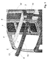
- the front cross member comprises the longitudinal walls 4 and 5, which, in this case, have a substantially L-shaped cross-section, formed for example in the case of the longitudinal wall 4 by the flaps 6 and 7.
- the first longitudinal wall 4 is arranged with the ends overlapping the end portions 8 and 9 of the box-type members 2 and 3 respectively, and joined thereto in a way that is known, preferably by means of spot welding. It may be sufficient to weld just one of the flaps, for example the wing 6, or weld spots may also be performed on the wing 7 in the overlapping area.
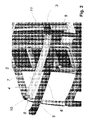
- Figures 2 and 3 illustrate the assembly of the second longitudinal wall 5 the ends of which are made to overlap and are joined to the end portions 10 and 11 of the longitudinal members.
- first and second longitudinal walls are joined together along the edges, for example the longitudinal flaps 12 and 13 and 14 and 15.
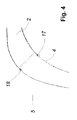
- Figure 4 shows a cross-sectional plan view of the area of the joint between the first and second members.
- the crosses 17 and 18 indicate the welding areas according to a possible embodiment of the invention.
- the end portions of the second (and of the other) box-type member may be the walls of the box-type system, or specific flaps, of a shape corresponding to that of the ends of the longitudinal walls of the first member, also depending on the angle that is formed between the box-type members on the joint.
- the curve of the front cross member joins that of the longitudinal box-type members, without forming sharp corners.
- the other box-type systems can also be formed as described, i.e. by first and second longitudinal walls joined as described above, and joined at the ends to a box-type member, which may be a knot or a joining element, or to the first box-type member.
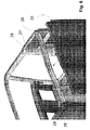
- Figures 5 - 8 illustrate the joint of a top rear cross member of the cab of a truck.
- a first longitudinal wall 21 is joined to the end portions 23 and 24 of other box-type members, the longitudinal box-type members 25 and 26.
- the second wall 22 is part of a metal plate 27 that constitutes one of the walls of the cab and is joined to the end portions 28 and 29 of the box-type members 25 and 26.
- one of the longitudinal walls is part of a larger metal plate, constituting part of a wall of the cab that is not a part of the box-type system, is a particular embodiment of the invention.
- the walls of the box-type systems may be obtained for example by forming.
- the joint can be performed along the longitudinal edges, for example by means of the flaps 30 with 31 and 32 with the actual wall 27, which also acts as a wing in this case.
- Other members may be attached to the longitudinal walls, in order to form other box-type sections or reinforcements.
- U-shaped members 35 and 36 are attached to the wall 21, in which a specific seat is provided, as shown in one wing of the longitudinal wall 21. These may form, with the wall 27, vertical reinforcement box-type systems.
- first longitudinal wall can be joined to the end portions of the second (and other) member by placing it against the latter from what will be the inside (example in figures 5-8) of the first member, or from the outside (example in figures 1-4), and can be joined to the end portions of the other members from its external or internal face respectively.
- the second longitudinal wall is preferably placed from the outside. Depending on the specific choices and requirements, the overall dimensions of the end portions must be taken into account in order to facilitate positioning.
- Figures 8 and 9 illustrate the extreme simplicity of the joint obtained according to the present invention compared to the prior art. Note how the continuity between the box-type systems is assured and the absence of any diaphragms or projecting flaps. With the system according to the present invention the parts are joined together more simply and faster, and fewer formed parts are needed. No jointed parts are required and parts can be set in place with less precision without causing any inconvenience. Fewer holes are also required for the electrodes in the case of spot welding (one for each joint between box-type systems). The absence of welds on external flaps or diaphragms perpendicular to the walls is advantageous in terms of mechanical strength. The weld spots (or glue points) in the system according to the present invention are able to withstand shearing stress. The result is a considerable increase in the mechanical strength of the box-type system in terms of bending and particularly torsional stress.
Landscapes
- Engineering & Computer Science (AREA)
- Chemical & Material Sciences (AREA)
- Combustion & Propulsion (AREA)
- Transportation (AREA)
- Mechanical Engineering (AREA)
- Manufacturing & Machinery (AREA)
- Body Structure For Vehicles (AREA)
- Automobile Manufacture Line, Endless Track Vehicle, Trailer (AREA)
- Portable Nailing Machines And Staplers (AREA)
Abstract
a first box-type member (1) comprising two longitudinal walls (4, 5, 21, 22) having a cross-section that forms a bend or a curve;
a second box-type member (2, 3, 23, 24) joined to each of said walls by means of the partial overlapping of an end portion thereof (8, 9, 10, 11, 23, 24) and one end of said wall.
Description
- The present invention relates to a box-type structure for the production of body structures for vehicles, motor cars, trucks, vans, etc., referred to in the following description as a structure for vehicle cab and the relative method of producing said structure.
- Vehicle bodies, for example truck cabs, normally comprise box-type sections which are part of the structure of the walls, floor and roof. Said box-type sections arranged for example on the corners of the structure and in particular on the corners joining the roof to the walls, are joined to the metal plates, or are partially formed by the metal plates that constitute said walls and roof and provide the required strength. These box-type structures are substantially tubiform structures with a square or rectangular cross-section and they intersect with one another in a series of knots. For example the roof generally comprises a front cross member arranged above the windscreen, joined at the ends to two longitudinal box-type structures, and two upright members. The ends of the cross member may be curved so as to meet the ends of the longitudinal box-type structures leaving the knot, forming a rounded corner. This is especially the case of the front cross member, while as a general rule the rear cross member is arranged so as to be substantially perpendicular in relation to the longitudinal box-type structures. The metal plates which form the walls and roof are joined to the box-type structures in different ways, and other intermediate box-type structures are attached to said metal plates to provide reinforcement. The joint between the box-type structures in correspondence with the knots is often achieved by welding, usually spot welding on flaps arranged transversely to said box-type structures, sometimes projecting towards the outside of said box-type structures and joining elements are needed between the knot and box-type structure. Some of these elements generally consist of separators arranged between a box-type structure and the knot or between different portions of the box-type structure.
- The methods used to achieve the joints on the knots are very complex and require a number of welding operations between different parts. Furthermore the flexural strength and resistance to torsional stress of the box-type structures on said joints are not ideal; this is made worse by the fact that, in case of projecting flaps, given the dimensions of the equipment that is used, spot welding is often performed at a certain distance from the walls of the box-type structure, which means that due to the arm formed by the wing the welded joint is exposed to considerable torsional stress and bending or tractive force. Finally, to enable access by spot welding equipment, many holes must be made in the side walls and these must then be reclosed.
- The problems described above have now been solved according to the present invention with a box-type system for a vehicle body comprising:
- a first box-type member comprising two longitudinal walls having a cross-section that forms a bend or a curve;
- a second box-type member joined to each of said walls by means of the partial overlapping of an end portion thereof and one end of said wall.
- Preferably the concave part of the cross-section of each of the longitudinal walls is arranged so as to face the other longitudinal wall.
- The joint, and this applies throughout this description unless otherwise specified, may be achieved using any method known in the prior art, such as welding, preferably spot welding, or brazing, braze welding or glueing.
- The various parts are preferably joined together by means of welding which is always performed on the junction plane of said parts without the need for fringing/bending, joining flaps.
- According to a preferred embodiment, one or both of said longitudinal walls has a cross-section that is basically L-shaped. More preferably said longitudinal walls are joined together along the longitudinal edges, for example by means of overlapping longitudinal flaps. The first box-type member may be straight in the longitudinal direction, or curved, and thus also the two longitudinal walls.
- Preferably the first member is joined to the second member, as illustrated, at one end, and at the other to another member, to create a structure that may be symmetrical.
- According to one embodiment of the invention, the first member may be a cross member of the structure of the cab of a vehicle, and may be for example the top front cross member, above the windscreen, or the top rear cross member, with the second and other longitudinal box-type members arranged between the walls and the roof.
- The invention also relates to a method of producing a box-type system comprising the following steps:
- overlapping and joining of one end of a first longitudinal wall and an end portion of a second box-type member;
- overlapping and joining of one end of a second longitudinal wall and a second end portion of the second box-type member, so as to form a first box-type member defined by said first and second longitudinal walls;
- optionally of joining said first and second longitudinal walls together along the longitudinal edges.
- It is particular object of the present invention the content of the appended claims.
- The present invention will now be illustrated by means of the following detailed description of preferred, but not exclusive embodiments, provided merely by way of example, with the help of the drawings attached hereto, in which:
- figures 1 to 3 are schematic diagrams of a perspective view of various steps in the assembly of a top front cross member of a truck cab, which is part of a system according to the present invention;
- figure 4 is a schematic diagram of a top sectional view of a part of the cross member in the previous drawings joined according to the present invention to a second box-type member;
- figures 5 to 7 are schematic diagrams of a perspective view of various steps in the assembly of a top rear cross member of a truck cab, which is part of a system according to the present invention;
- figure 8 is a schematic diagram of a top sectional view of a part of the cross member of the previous drawings joined to a second box-type member;
- figure 9 is a schematic diagram of a top sectional view of a part of a top rear cross member assembled according to the prior art.
- With reference to figures 1, 2 and 3, a box-type system is described, said system comprising the top front cross member of the cab of a truck and the relative steps in the assembly thereof; the
cross member 1 constitutes the first box-type member as described above, the longitudinal box-type systems longitudinal walls longitudinal wall 4 by theflaps longitudinal wall 4 is arranged with the ends overlapping theend portions type members wing 6, or weld spots may also be performed on thewing 7 in the overlapping area. - Figures 2 and 3 illustrate the assembly of the second
longitudinal wall 5 the ends of which are made to overlap and are joined to theend portions - According to a preferred embodiment the first and second longitudinal walls are joined together along the edges, for example the
longitudinal flaps crosses - The end portions of the second (and of the other) box-type member may be the walls of the box-type system, or specific flaps, of a shape corresponding to that of the ends of the longitudinal walls of the first member, also depending on the angle that is formed between the box-type members on the joint. For example, in the case in figures 1 to 4, the curve of the front cross member joins that of the longitudinal box-type members, without forming sharp corners. The other box-type systems can also be formed as described, i.e. by first and second longitudinal walls joined as described above, and joined at the ends to a box-type member, which may be a knot or a joining element, or to the first box-type member.
- Figures 5 - 8 illustrate the joint of a top rear cross member of the cab of a truck. Once again a first
longitudinal wall 21 is joined to theend portions type members second wall 22 is part of ametal plate 27 that constitutes one of the walls of the cab and is joined to theend portions type members - The fact that one of the longitudinal walls is part of a larger metal plate, constituting part of a wall of the cab that is not a part of the box-type system, is a particular embodiment of the invention. The walls of the box-type systems may be obtained for example by forming. Also in this case the joint can be performed along the longitudinal edges, for example by means of the
flaps 30 with 31 and 32 with theactual wall 27, which also acts as a wing in this case. Other members may be attached to the longitudinal walls, in order to form other box-type sections or reinforcements. For example U-shapedmembers wall 21, in which a specific seat is provided, as shown in one wing of thelongitudinal wall 21. These may form, with thewall 27, vertical reinforcement box-type systems.
it must be noted how the first longitudinal wall can be joined to the end portions of the second (and other) member by placing it against the latter from what will be the inside (example in figures 5-8) of the first member, or from the outside (example in figures 1-4), and can be joined to the end portions of the other members from its external or internal face respectively. The second longitudinal wall is preferably placed from the outside. Depending on the specific choices and requirements, the overall dimensions of the end portions must be taken into account in order to facilitate positioning. - Figures 8 and 9 (the crosses indicate possible weld spots) illustrate the extreme simplicity of the joint obtained according to the present invention compared to the prior art. Note how the continuity between the box-type systems is assured and the absence of any diaphragms or projecting flaps. With the system according to the present invention the parts are joined together more simply and faster, and fewer formed parts are needed. No jointed parts are required and parts can be set in place with less precision without causing any inconvenience. Fewer holes are also required for the electrodes in the case of spot welding (one for each joint between box-type systems). The absence of welds on external flaps or diaphragms perpendicular to the walls is advantageous in terms of mechanical strength. The weld spots (or glue points) in the system according to the present invention are able to withstand shearing stress. The result is a considerable increase in the mechanical strength of the box-type system in terms of bending and particularly torsional stress.
Claims (11)
- Box-type system for vehicle body characterized in that it comprises:a first box-type member (1) comprising two longitudinal walls (4, 5, 21, 22) having a cross-section that forms a bend or a curve;a second box-type member (2, 3, 23, 24) joined to each of said walls by means of the partial overlapping of an end portion thereof (8, 9, 10, 11, 23, 24) and one end of said wall.
- System according to claim 1, characterized in that the concave part of the cross-section of each of the longitudinal walls is arranged so as to face the other longitudinal wall.
- System according to any of the previous claims, characterized in that the joint is achieved by welding, brazing, braze welding or glueing.
- System according to claim 3, characterized in that the joint is achieved by spot welding.
- System according to any of the previous claims, characterized in that at least one of said longitudinal walls has a cross-section that is essentially L-shaped.
- System according to any of the previous claims, characterized in that said longitudinal walls are joined together along the longitudinal edges, preferably by means of overlapping longitudinal flaps (12, 14, 13, 15, 30, 31, 32, 27).
- System according to any of the previous claims, characterized in that the first member is the top front cross member of the structure of the cab of a vehicle or the top rear cross member, and the second member is a longitudinal box-type system arranged between the walls and the roof or a knot or a joining element.
- System according to claim 7, characterized in that the second wall (22) is part of a metal plate (27) that constitutes one of the walls.
- Cab for truck comprising a box-type system according to any of the previous claims.
- Method for producing a box-type system comprising the following steps:overlapping and joining one end of a first longitudinal wall and an end portion of a second box-type member;overlapping and joining one end of a second longitudinal wall and a second end portion of the second box-type member, so as to form a first box-type structure defined by said first and second longitudinal walls;joining together said first and second longitudinal walls along the longitudinal edges.
- Method according to claim 10, characterized in that it comprises joining together said first and second longitudinal walls along the longitudinal edges.
Applications Claiming Priority (1)
| Application Number | Priority Date | Filing Date | Title |
|---|---|---|---|
| IT001948A ITMI20061948A1 (en) | 2006-10-11 | 2006-10-11 | BOXED SYSTEM FOR TRUCK CABIN AND METHOD OF REALIZATION |
Publications (3)
| Publication Number | Publication Date |
|---|---|
| EP1911663A2 true EP1911663A2 (en) | 2008-04-16 |
| EP1911663A3 EP1911663A3 (en) | 2008-05-07 |
| EP1911663B1 EP1911663B1 (en) | 2011-10-26 |
Family
ID=37831515
Family Applications (1)
| Application Number | Title | Priority Date | Filing Date |
|---|---|---|---|
| EP07118210A Active EP1911663B1 (en) | 2006-10-11 | 2007-10-10 | Box-type structure for the cab of a truck and method of production |
Country Status (8)
| Country | Link |
|---|---|
| EP (1) | EP1911663B1 (en) |
| CN (1) | CN101161534B (en) |
| AT (1) | ATE530425T1 (en) |
| AU (1) | AU2007221775B2 (en) |
| BR (1) | BRPI0703414B1 (en) |
| ES (1) | ES2375659T3 (en) |
| IT (1) | ITMI20061948A1 (en) |
| RU (1) | RU2441793C2 (en) |
Families Citing this family (2)
| Publication number | Priority date | Publication date | Assignee | Title |
|---|---|---|---|---|
| RU184989U1 (en) * | 2018-07-31 | 2018-11-15 | Публичное акционерное общество "АВТОВАЗ" | The bodywork of the car in the zone of connection of the roof cross member to the sidewall |
| CN113909803A (en) * | 2021-09-13 | 2022-01-11 | 云南昆船环保技术有限公司 | Intelligent continuous production method for square cabin |
Citations (1)
| Publication number | Priority date | Publication date | Assignee | Title |
|---|---|---|---|---|
| GB2281047A (en) | 1993-08-20 | 1995-02-22 | Smith Corp A O | Structural member and method for forming the same |
Family Cites Families (6)
| Publication number | Priority date | Publication date | Assignee | Title |
|---|---|---|---|---|
| SU1364523A1 (en) * | 1985-10-14 | 1988-01-07 | Всесоюзный Научно-Исследовательский,Проектно-Конструкторский И Технологический Институт Безрельсового Электрифицированного Транспорта С Опытным Производством | Vehicle |
| DE3811427A1 (en) * | 1988-04-05 | 1989-10-26 | Audi Ag | CONNECTING ARRANGEMENT OF BODY PARTS |
| CN2233872Y (en) * | 1995-04-26 | 1996-08-28 | 北京吉普汽车有限公司 | Hood for light cross-country car |
| EP1658218B1 (en) * | 2003-08-27 | 2007-10-31 | ThyssenKrupp Steel AG | Post in a carrier structure of a motor vehicle in a spaceframe style |
| US7104596B2 (en) * | 2003-10-16 | 2006-09-12 | Honda Motor Co., Ltd. | Vehicle body structure |
| FR2872123B1 (en) * | 2004-06-29 | 2009-06-05 | Kubota Kk | VEHICLE WORKING WITH A CABIN |
-
2006
- 2006-10-11 IT IT001948A patent/ITMI20061948A1/en unknown
-
2007
- 2007-10-02 AU AU2007221775A patent/AU2007221775B2/en not_active Ceased
- 2007-10-10 EP EP07118210A patent/EP1911663B1/en active Active
- 2007-10-10 AT AT07118210T patent/ATE530425T1/en not_active IP Right Cessation
- 2007-10-10 RU RU2007137646/11A patent/RU2441793C2/en active
- 2007-10-10 ES ES07118210T patent/ES2375659T3/en active Active
- 2007-10-11 CN CN2007101822963A patent/CN101161534B/en not_active Expired - Fee Related
- 2007-10-11 BR BRPI0703414-8A patent/BRPI0703414B1/en active IP Right Grant
Patent Citations (1)
| Publication number | Priority date | Publication date | Assignee | Title |
|---|---|---|---|---|
| GB2281047A (en) | 1993-08-20 | 1995-02-22 | Smith Corp A O | Structural member and method for forming the same |
Also Published As
| Publication number | Publication date |
|---|---|
| CN101161534A (en) | 2008-04-16 |
| RU2007137646A (en) | 2009-04-20 |
| EP1911663B1 (en) | 2011-10-26 |
| CN101161534B (en) | 2012-06-27 |
| AU2007221775B2 (en) | 2012-09-20 |
| ES2375659T3 (en) | 2012-03-05 |
| ITMI20061948A1 (en) | 2008-04-12 |
| ATE530425T1 (en) | 2011-11-15 |
| RU2441793C2 (en) | 2012-02-10 |
| AU2007221775A1 (en) | 2008-05-01 |
| BRPI0703414A2 (en) | 2009-06-09 |
| BRPI0703414B1 (en) | 2019-07-16 |
| EP1911663A3 (en) | 2008-05-07 |
Similar Documents
| Publication | Publication Date | Title |
|---|---|---|
| US7500802B2 (en) | Three-dimensional node structure | |
| EP2236395B1 (en) | Connection structure of tube-shaped frames, corresponding method and vehicle body | |
| US8366184B2 (en) | Structure for vehicle body upper portion | |
| CN102963422B (en) | There is the vehicle support deck of the interlock feature for connecting differing materials | |
| JP2003212148A (en) | Center pillar upper coupling structure of automobile | |
| WO2010100805A1 (en) | Vehicle body framework structure | |
| JP4696756B2 (en) | Upper body structure of automobile | |
| JP6269843B2 (en) | Junction structure | |
| CN108791524B (en) | Underbody structure for a two-track vehicle | |
| CN109789882A (en) | The skeleton structure of rail truck and have the rail truck skeleton structure side structure | |
| EP1911663B1 (en) | Box-type structure for the cab of a truck and method of production | |
| JP3925099B2 (en) | Panel connection structure | |
| KR102757871B1 (en) | Vehicle body connection structure | |
| JP5086726B2 (en) | Vehicle panel structure | |
| JP2017177915A (en) | Body structure | |
| CN110450858A (en) | Vehicle structure | |
| JP2006341763A (en) | Bogie frame for railway vehicles | |
| JPH06127433A (en) | Car body structure | |
| WO1997010138A1 (en) | Vehicle cab and method for assembling such a cab by welding | |
| JPS60131376A (en) | Joint structure of pillar and side sill | |
| CN105667606A (en) | Connecting structure | |
| JP4227920B2 (en) | Railway vehicle structure | |
| JP5637904B2 (en) | Member connection structure | |
| JPH0736870Y2 (en) | Inner channel connection structure | |
| JP2008087543A (en) | Vehicular panel structure |
Legal Events
| Date | Code | Title | Description |
|---|---|---|---|
| PUAI | Public reference made under article 153(3) epc to a published international application that has entered the european phase |
Free format text: ORIGINAL CODE: 0009012 |
|
| PUAL | Search report despatched |
Free format text: ORIGINAL CODE: 0009013 |
|
| AK | Designated contracting states |
Kind code of ref document: A2 Designated state(s): AT BE BG CH CY CZ DE DK EE ES FI FR GB GR HU IE IS IT LI LT LU LV MC MT NL PL PT RO SE SI SK TR |
|
| AX | Request for extension of the european patent |
Extension state: AL BA HR MK RS |
|
| AK | Designated contracting states |
Kind code of ref document: A3 Designated state(s): AT BE BG CH CY CZ DE DK EE ES FI FR GB GR HU IE IS IT LI LT LU LV MC MT NL PL PT RO SE SI SK TR |
|
| AX | Request for extension of the european patent |
Extension state: AL BA HR MK RS |
|
| 17P | Request for examination filed |
Effective date: 20081106 |
|
| AKX | Designation fees paid |
Designated state(s): AT BE BG CH CY CZ DE DK EE ES FI FR GB GR HU IE IS IT LI LT LU LV MC MT NL PL PT RO SE SI SK TR |
|
| 17Q | First examination report despatched |
Effective date: 20081223 |
|
| GRAP | Despatch of communication of intention to grant a patent |
Free format text: ORIGINAL CODE: EPIDOSNIGR1 |
|
| GRAS | Grant fee paid |
Free format text: ORIGINAL CODE: EPIDOSNIGR3 |
|
| GRAA | (expected) grant |
Free format text: ORIGINAL CODE: 0009210 |
|
| AK | Designated contracting states |
Kind code of ref document: B1 Designated state(s): AT BE BG CH CY CZ DE DK EE ES FI FR GB GR HU IE IS IT LI LT LU LV MC MT NL PL PT RO SE SI SK TR |
|
| REG | Reference to a national code |
Ref country code: GB Ref legal event code: FG4D |
|
| REG | Reference to a national code |
Ref country code: CH Ref legal event code: EP |
|
| REG | Reference to a national code |
Ref country code: IE Ref legal event code: FG4D |
|
| REG | Reference to a national code |
Ref country code: DE Ref legal event code: R096 Ref document number: 602007018158 Country of ref document: DE Effective date: 20111222 |
|
| REG | Reference to a national code |
Ref country code: SE Ref legal event code: TRGR |
|
| REG | Reference to a national code |
Ref country code: NL Ref legal event code: T3 |
|
| REG | Reference to a national code |
Ref country code: ES Ref legal event code: FG2A Ref document number: 2375659 Country of ref document: ES Kind code of ref document: T3 Effective date: 20120305 |
|
| LTIE | Lt: invalidation of european patent or patent extension |
Effective date: 20111026 |
|
| REG | Reference to a national code |
Ref country code: AT Ref legal event code: MK05 Ref document number: 530425 Country of ref document: AT Kind code of ref document: T Effective date: 20111026 |
|
| PG25 | Lapsed in a contracting state [announced via postgrant information from national office to epo] |
Ref country code: IS Free format text: LAPSE BECAUSE OF FAILURE TO SUBMIT A TRANSLATION OF THE DESCRIPTION OR TO PAY THE FEE WITHIN THE PRESCRIBED TIME-LIMIT Effective date: 20120226 Ref country code: BE Free format text: LAPSE BECAUSE OF FAILURE TO SUBMIT A TRANSLATION OF THE DESCRIPTION OR TO PAY THE FEE WITHIN THE PRESCRIBED TIME-LIMIT Effective date: 20111026 Ref country code: LT Free format text: LAPSE BECAUSE OF FAILURE TO SUBMIT A TRANSLATION OF THE DESCRIPTION OR TO PAY THE FEE WITHIN THE PRESCRIBED TIME-LIMIT Effective date: 20111026 |
|
| PG25 | Lapsed in a contracting state [announced via postgrant information from national office to epo] |
Ref country code: SI Free format text: LAPSE BECAUSE OF FAILURE TO SUBMIT A TRANSLATION OF THE DESCRIPTION OR TO PAY THE FEE WITHIN THE PRESCRIBED TIME-LIMIT Effective date: 20111026 Ref country code: PL Free format text: LAPSE BECAUSE OF FAILURE TO SUBMIT A TRANSLATION OF THE DESCRIPTION OR TO PAY THE FEE WITHIN THE PRESCRIBED TIME-LIMIT Effective date: 20111026 Ref country code: LV Free format text: LAPSE BECAUSE OF FAILURE TO SUBMIT A TRANSLATION OF THE DESCRIPTION OR TO PAY THE FEE WITHIN THE PRESCRIBED TIME-LIMIT Effective date: 20111026 Ref country code: GR Free format text: LAPSE BECAUSE OF FAILURE TO SUBMIT A TRANSLATION OF THE DESCRIPTION OR TO PAY THE FEE WITHIN THE PRESCRIBED TIME-LIMIT Effective date: 20120127 Ref country code: PT Free format text: LAPSE BECAUSE OF FAILURE TO SUBMIT A TRANSLATION OF THE DESCRIPTION OR TO PAY THE FEE WITHIN THE PRESCRIBED TIME-LIMIT Effective date: 20120227 |
|
| PG25 | Lapsed in a contracting state [announced via postgrant information from national office to epo] |
Ref country code: CY Free format text: LAPSE BECAUSE OF FAILURE TO SUBMIT A TRANSLATION OF THE DESCRIPTION OR TO PAY THE FEE WITHIN THE PRESCRIBED TIME-LIMIT Effective date: 20111026 |
|
| PG25 | Lapsed in a contracting state [announced via postgrant information from national office to epo] |
Ref country code: CZ Free format text: LAPSE BECAUSE OF FAILURE TO SUBMIT A TRANSLATION OF THE DESCRIPTION OR TO PAY THE FEE WITHIN THE PRESCRIBED TIME-LIMIT Effective date: 20111026 Ref country code: SK Free format text: LAPSE BECAUSE OF FAILURE TO SUBMIT A TRANSLATION OF THE DESCRIPTION OR TO PAY THE FEE WITHIN THE PRESCRIBED TIME-LIMIT Effective date: 20111026 Ref country code: EE Free format text: LAPSE BECAUSE OF FAILURE TO SUBMIT A TRANSLATION OF THE DESCRIPTION OR TO PAY THE FEE WITHIN THE PRESCRIBED TIME-LIMIT Effective date: 20111026 Ref country code: DK Free format text: LAPSE BECAUSE OF FAILURE TO SUBMIT A TRANSLATION OF THE DESCRIPTION OR TO PAY THE FEE WITHIN THE PRESCRIBED TIME-LIMIT Effective date: 20111026 Ref country code: BG Free format text: LAPSE BECAUSE OF FAILURE TO SUBMIT A TRANSLATION OF THE DESCRIPTION OR TO PAY THE FEE WITHIN THE PRESCRIBED TIME-LIMIT Effective date: 20120126 |
|
| PG25 | Lapsed in a contracting state [announced via postgrant information from national office to epo] |
Ref country code: RO Free format text: LAPSE BECAUSE OF FAILURE TO SUBMIT A TRANSLATION OF THE DESCRIPTION OR TO PAY THE FEE WITHIN THE PRESCRIBED TIME-LIMIT Effective date: 20111026 |
|
| PLBE | No opposition filed within time limit |
Free format text: ORIGINAL CODE: 0009261 |
|
| STAA | Information on the status of an ep patent application or granted ep patent |
Free format text: STATUS: NO OPPOSITION FILED WITHIN TIME LIMIT |
|
| 26N | No opposition filed |
Effective date: 20120727 |
|
| REG | Reference to a national code |
Ref country code: DE Ref legal event code: R097 Ref document number: 602007018158 Country of ref document: DE Effective date: 20120727 |
|
| PG25 | Lapsed in a contracting state [announced via postgrant information from national office to epo] |
Ref country code: AT Free format text: LAPSE BECAUSE OF FAILURE TO SUBMIT A TRANSLATION OF THE DESCRIPTION OR TO PAY THE FEE WITHIN THE PRESCRIBED TIME-LIMIT Effective date: 20111026 |
|
| PG25 | Lapsed in a contracting state [announced via postgrant information from national office to epo] |
Ref country code: MC Free format text: LAPSE BECAUSE OF NON-PAYMENT OF DUE FEES Effective date: 20121031 |
|
| REG | Reference to a national code |
Ref country code: CH Ref legal event code: PL |
|
| PG25 | Lapsed in a contracting state [announced via postgrant information from national office to epo] |
Ref country code: FI Free format text: LAPSE BECAUSE OF FAILURE TO SUBMIT A TRANSLATION OF THE DESCRIPTION OR TO PAY THE FEE WITHIN THE PRESCRIBED TIME-LIMIT Effective date: 20111026 |
|
| REG | Reference to a national code |
Ref country code: IE Ref legal event code: MM4A |
|
| PG25 | Lapsed in a contracting state [announced via postgrant information from national office to epo] |
Ref country code: CH Free format text: LAPSE BECAUSE OF NON-PAYMENT OF DUE FEES Effective date: 20121031 Ref country code: LI Free format text: LAPSE BECAUSE OF NON-PAYMENT OF DUE FEES Effective date: 20121031 Ref country code: IE Free format text: LAPSE BECAUSE OF NON-PAYMENT OF DUE FEES Effective date: 20121010 |
|
| PG25 | Lapsed in a contracting state [announced via postgrant information from national office to epo] |
Ref country code: MT Free format text: LAPSE BECAUSE OF FAILURE TO SUBMIT A TRANSLATION OF THE DESCRIPTION OR TO PAY THE FEE WITHIN THE PRESCRIBED TIME-LIMIT Effective date: 20111026 |
|
| PG25 | Lapsed in a contracting state [announced via postgrant information from national office to epo] |
Ref country code: TR Free format text: LAPSE BECAUSE OF FAILURE TO SUBMIT A TRANSLATION OF THE DESCRIPTION OR TO PAY THE FEE WITHIN THE PRESCRIBED TIME-LIMIT Effective date: 20111026 |
|
| PG25 | Lapsed in a contracting state [announced via postgrant information from national office to epo] |
Ref country code: LU Free format text: LAPSE BECAUSE OF NON-PAYMENT OF DUE FEES Effective date: 20121010 |
|
| PG25 | Lapsed in a contracting state [announced via postgrant information from national office to epo] |
Ref country code: HU Free format text: LAPSE BECAUSE OF FAILURE TO SUBMIT A TRANSLATION OF THE DESCRIPTION OR TO PAY THE FEE WITHIN THE PRESCRIBED TIME-LIMIT Effective date: 20071010 |
|
| REG | Reference to a national code |
Ref country code: FR Ref legal event code: PLFP Year of fee payment: 9 |
|
| REG | Reference to a national code |
Ref country code: FR Ref legal event code: PLFP Year of fee payment: 10 |
|
| REG | Reference to a national code |
Ref country code: FR Ref legal event code: PLFP Year of fee payment: 11 |
|
| REG | Reference to a national code |
Ref country code: FR Ref legal event code: PLFP Year of fee payment: 12 |
|
| PGFP | Annual fee paid to national office [announced via postgrant information from national office to epo] |
Ref country code: NL Payment date: 20221025 Year of fee payment: 16 |
|
| PGFP | Annual fee paid to national office [announced via postgrant information from national office to epo] |
Ref country code: SE Payment date: 20221024 Year of fee payment: 16 |
|
| P01 | Opt-out of the competence of the unified patent court (upc) registered |
Effective date: 20230523 |
|
| REG | Reference to a national code |
Ref country code: SE Ref legal event code: EUG |
|
| REG | Reference to a national code |
Ref country code: NL Ref legal event code: MM Effective date: 20231101 |
|
| PG25 | Lapsed in a contracting state [announced via postgrant information from national office to epo] |
Ref country code: NL Free format text: LAPSE BECAUSE OF NON-PAYMENT OF DUE FEES Effective date: 20231101 |
|
| PG25 | Lapsed in a contracting state [announced via postgrant information from national office to epo] |
Ref country code: NL Free format text: LAPSE BECAUSE OF NON-PAYMENT OF DUE FEES Effective date: 20231101 |
|
| PG25 | Lapsed in a contracting state [announced via postgrant information from national office to epo] |
Ref country code: SE Free format text: LAPSE BECAUSE OF NON-PAYMENT OF DUE FEES Effective date: 20231011 |
|
| PGFP | Annual fee paid to national office [announced via postgrant information from national office to epo] |
Ref country code: DE Payment date: 20241029 Year of fee payment: 18 |
|
| PGFP | Annual fee paid to national office [announced via postgrant information from national office to epo] |
Ref country code: GB Payment date: 20241022 Year of fee payment: 18 |
|
| PGFP | Annual fee paid to national office [announced via postgrant information from national office to epo] |
Ref country code: FR Payment date: 20241025 Year of fee payment: 18 |
|
| PGFP | Annual fee paid to national office [announced via postgrant information from national office to epo] |
Ref country code: IT Payment date: 20241008 Year of fee payment: 18 Ref country code: ES Payment date: 20241118 Year of fee payment: 18 |