EP1911646A2 - Vehicle brake hydraulic pressure control unit - Google Patents
Vehicle brake hydraulic pressure control unit Download PDFInfo
- Publication number
- EP1911646A2 EP1911646A2 EP07020065A EP07020065A EP1911646A2 EP 1911646 A2 EP1911646 A2 EP 1911646A2 EP 07020065 A EP07020065 A EP 07020065A EP 07020065 A EP07020065 A EP 07020065A EP 1911646 A2 EP1911646 A2 EP 1911646A2
- Authority
- EP
- European Patent Office
- Prior art keywords
- mounting hole
- hole portion
- hydraulic pressure
- control unit
- pressure control
- Prior art date
- Legal status (The legal status is an assumption and is not a legal conclusion. Google has not performed a legal analysis and makes no representation as to the accuracy of the status listed.)
- Granted
Links
Images


Classifications
-
- B—PERFORMING OPERATIONS; TRANSPORTING
- B60—VEHICLES IN GENERAL
- B60T—VEHICLE BRAKE CONTROL SYSTEMS OR PARTS THEREOF; BRAKE CONTROL SYSTEMS OR PARTS THEREOF, IN GENERAL; ARRANGEMENT OF BRAKING ELEMENTS ON VEHICLES IN GENERAL; PORTABLE DEVICES FOR PREVENTING UNWANTED MOVEMENT OF VEHICLES; VEHICLE MODIFICATIONS TO FACILITATE COOLING OF BRAKES
- B60T8/00—Arrangements for adjusting wheel-braking force to meet varying vehicular or ground-surface conditions, e.g. limiting or varying distribution of braking force
- B60T8/32—Arrangements for adjusting wheel-braking force to meet varying vehicular or ground-surface conditions, e.g. limiting or varying distribution of braking force responsive to a speed condition, e.g. acceleration or deceleration
- B60T8/34—Arrangements for adjusting wheel-braking force to meet varying vehicular or ground-surface conditions, e.g. limiting or varying distribution of braking force responsive to a speed condition, e.g. acceleration or deceleration having a fluid pressure regulator responsive to a speed condition
- B60T8/36—Arrangements for adjusting wheel-braking force to meet varying vehicular or ground-surface conditions, e.g. limiting or varying distribution of braking force responsive to a speed condition, e.g. acceleration or deceleration having a fluid pressure regulator responsive to a speed condition including a pilot valve responding to an electromagnetic force
- B60T8/3615—Electromagnetic valves specially adapted for anti-lock brake and traction control systems
- B60T8/3675—Electromagnetic valves specially adapted for anti-lock brake and traction control systems integrated in modulator units
-
- F—MECHANICAL ENGINEERING; LIGHTING; HEATING; WEAPONS; BLASTING
- F15—FLUID-PRESSURE ACTUATORS; HYDRAULICS OR PNEUMATICS IN GENERAL
- F15B—SYSTEMS ACTING BY MEANS OF FLUIDS IN GENERAL; FLUID-PRESSURE ACTUATORS, e.g. SERVOMOTORS; DETAILS OF FLUID-PRESSURE SYSTEMS, NOT OTHERWISE PROVIDED FOR
- F15B13/00—Details of servomotor systems ; Valves for servomotor systems
- F15B13/02—Fluid distribution or supply devices characterised by their adaptation to the control of servomotors
- F15B13/06—Fluid distribution or supply devices characterised by their adaptation to the control of servomotors for use with two or more servomotors
- F15B13/08—Assemblies of units, each for the control of a single servomotor only
- F15B13/0803—Modular units
- F15B13/0807—Manifolds
- F15B13/0814—Monoblock manifolds
-
- F—MECHANICAL ENGINEERING; LIGHTING; HEATING; WEAPONS; BLASTING
- F15—FLUID-PRESSURE ACTUATORS; HYDRAULICS OR PNEUMATICS IN GENERAL
- F15B—SYSTEMS ACTING BY MEANS OF FLUIDS IN GENERAL; FLUID-PRESSURE ACTUATORS, e.g. SERVOMOTORS; DETAILS OF FLUID-PRESSURE SYSTEMS, NOT OTHERWISE PROVIDED FOR
- F15B13/00—Details of servomotor systems ; Valves for servomotor systems
- F15B13/02—Fluid distribution or supply devices characterised by their adaptation to the control of servomotors
- F15B13/06—Fluid distribution or supply devices characterised by their adaptation to the control of servomotors for use with two or more servomotors
- F15B13/08—Assemblies of units, each for the control of a single servomotor only
- F15B13/0803—Modular units
- F15B13/0832—Modular valves
- F15B13/0835—Cartridge type valves
Definitions
- the present invention relates to a vehicle brake hydraulic pressure control unit which is characterized in a mounting construction of assembled parts such as an electromagnetic valve, a pump and a pressure sensor.
- vehicle brake hydraulic pressure control units for controlling the magnitude of a brake hydraulic pressure which is applied to wheel brakes
- vehicle brake hydraulic pressure control units which include a base body which incorporates therein a brake fluid flow path and assembled parts such as an electromagnetic valve, a pump and a pressure sensor (for example, refer to Japanese Patent Unexamined Publication No. JP-A-2001-280533 ).
- an electromagnetic valve which is one of assembled parts, is assembled in place in a bottomed mounting hole portion which is provided in a base body in such a manner as to communicate with a flow path in an interior of the base body by depressing a relevant location of the surface of the base body thereinto.
- a plastically deformed portion is formed on a hole wall of the mounting hole portion by inserting a lower end portion of the electromagnetic valve into a lower portion of the mounting hole portion for clamping and thereafter pressing the surface of the base body around the periphery of an opening in the mounting hole portion, and the plastically deformed portion so formed is caused to enter a locking groove formed on an outer circumferential surface of the electromagnetic valve, so as to prevent the dislocation of the electromagnetic valve from the mounting hole portion.
- the lower end portion of the electromagnetic valve when the lower end portion of the electromagnetic valve is press fitted in the lower portion of the mounting hole portion, the lower end portion of the electromagnetic valve needs to be caused to slide along the hole wall of the mounting hole portion. Therefore, there may occur a case where fine chippings (metallic ones) are produced in the lower portion of the mounting hole portion, depending upon a combination of tolerances in the dimensions of the relevant parts.
- the aforesaid problem applies to the electromagnetic valve which constitutes the assembled part, in addition, the aforesaid problem applies to the pump, the reservoir and the pressure sensor when they constitute the assembled part.
- the invention has been made from the viewpoint of solving the problem, and an object thereof is to provide a vehicle brake hydraulic pressure control unit which can prevent the flow out into the brake fluid flow path of chippings produced when the assembled part is press fitted in the mounting hole portion in the base body.
- a vehicle brake hydraulic pressure control unit including:
- the assembled part means a general designation for parts which are assembled to the base body to embody a hydraulic circuit and it contains at least an electromagnetic valve, a pump, a reservoir, a pressure sensor and the like are included.
- “upper” and “lower” are based on the state in which the assembled part is assembled in place in the mounting hole portion, and the “lower end portion” of the assembled part means the end portion thereof which lies on the bottom surface side of the mounting hole portion.
- the vehicle brake hydraulic pressure control unit of the invention even in the event that chippings are produced when the assembled part is press fitted in the mounting hole portion in the base body, the chippings so produced can be sealed in the accommodation space. Namely, according the vehicle brake hydraulic pressure control unit of the invention, the mixing of chippings into brake fluid can be prevented. Therefore, the increase in siding resistance in the slide portion of the vehicle brake hydraulic pressure control unit can be suppressed, and furthermore, the wear of the seal portion can be prevented. In addition, by bringing the lower end surface of the assembled part into abutment with the bottom surface of the mounting hole portion, the inserting position of the assembled part is restricted.
- the hole wall of the mounting hole portion is clamped while maintaining the state in which the lower end surface of the assembled part is in abutment with the bottom surface of the mounting hole portion. Therefore, the assembled part is made difficult to be inclined when the assembled part is fixed. In addition, the lower end surface of the assembled part may be caused to sink into the bottom surface of the mounting hole portion.
- a lower end portion of the assembled part includes:
- a circumferential groove is provided on the inner circumferential surface of the mounting hole portion along a circumferential direction, and the accommodation space is further defined by the circumferential groove.
- a bottom groove is provided on the bottom surface of the mounting hole portion along an outer circumference of the bottom surface, and wherein the accommodation space is further defined by the bottom groove. Since working on the assembled part can be omitted or simplified in the event that the accommodation space is formed by working on the mounting hole portion, a conventional assembled part can be carried over for use in the vehicle brake hydraulic pressure control unit of the invention.
- the bottom groove can be formed by a candle-type drill, the bottom groove can be formed more simply and inexpensively then the circumferential groove.
- the lower end surface of the assembled part is formed into a shape which protrudes towards the bottom surface of the mounting hole portion.
- the mounting hole portion includes:
- a locking groove for a plastically deformed portion formed when a hole wall of the mounting hole portion is clamped to enter is formed on the outer circumferential surface of the assembled part, and an outside diameter of the assembled part at an upper side of the locking groove is made smaller than an outside diameter of assembled part at a lower side of the locking groove.
- the diameter of the mounting hole portion after plastic deformation (after clamping) also becomes smaller at the upper side than at the lower side of the locking groove. Consequently, when a force is applied to the assembled part in a direction in which the assembled part is pushed out from the mounting hole portion, a shear fracture plane is formed in such a manner as to rise obliquely upwards from an outer circumferential edge of the lower side of the locking groove. Namely, when the outside diameter of the locking groove is the same at the upper side as at the lower side of the locking groove, the shear fracture distance becomes equal to the groove width of the locking groove.
- the vehicle brake hydraulic pressure control unit since the shear fracture distance becomes equal to or larger than the groove width of the locking groove, even when the groove width of the locking groove is decreased, an assembling strength can be secured which is equal to the assembling strength that is provided when the outside diameter of the assembled part is made the same at the upper side as at the lower side of the locking groove.
- the vehicle brake hydraulic pressure control unit of the invention it is possible to prevent the flow out into the brake fluid flow path of chippings produced when the assembled part is press fitted in the mounting hole portion in the base body.
- a vehicle brake hydraulic pressure control unit U is configured to include a base body 1 which incorporates therein a brake fluid flow path, a normally open electromagnetic valve 2 which is an assembled part to be assembled in place in a mounting hole portion 10A formed in the base body 1 and the like.
- the vehicle brake hydraulic pressure control unit U includes a motor 7, an electronic control unit 8, a housing 9 and the like in addition to other assembled parts such as a normally closed electromagnetic valve 3, a reservoir 4, a pump 5 and a pressure sensor 6, since they are similar to those mounted in a conventional one, the detailed description thereof will be omitted here.
- the base body 1 is a member which is substantially a rectangular parallelepiped and which is made of aluminum alloy and incorporates therein a brake fluid flow path 1a (refer to Fig. 2).
- the mounting hole portion 10 in which the normally open electromagnetic valve 2 is mounted and a recessed portion 10B which is formed in such a manner as to surround the mounting hole portion 10A are formed in the base body 1.
- formed in the base body 1 are holes in which the normally closed electromagnetic valve 3, the reservoir 4, the pump 5, the pressure switch 6 and the like are mounted, an inlet port 1b to which a piping, not shown, which communicates with a master cylinder (not shown) is connected, outlet ports 1c to which pipings, not shown, which reach wheel brakes are connected, and the like.
- the respective holes are made to communicate with each other directly or via flow paths, not shown, which are formed in the interior of the base body 1.
- the mounting hole portion 10A is, as shown in Fig. 2, a bottomed hole which is formed in such a manner as to communicate with flow paths 1a, 1a formed in the interior of the base body 1.
- the mounting hole portion 10A includes a cylindrical abutment portion 11 (an inner circumferential sealing surface) which is formed in a lower portion (a deepest portion), a cylindrical introducing portion 12 which is formed in a location which lies shallower than the abutment portion 11, a truncated cone-shaped tapered portion 13 which connects the abutment portion 11 with the introducing portion 12, a cylindrical holding portion 14 which is formed in a location which lies shallower than the introducing portion 12 and a truncated cone-shaped connecting portion 15 which connects the introducing portion 12 with the holding portion 14.
- a diameter of the mounting hole portion 10A at the introducing portion 12 is made larger than a diameter at the abutment portion 11, and a diameter of the mounting hole portion 10A at the holding portion 14 is made larger than the diameter at the introducing portion 12.
- the mounting hole portion 10A is formed into a stepped cylindrical shape which sequentially increases in diameter as it extends from a bottom surface 16 (a bottom sealing surface) towards an opening thereof.
- One of the flow paths 1a, 1a is made to open to the bottom surface 16, while the other is made to open to the holding portion 14. Note that since the flow path 1a is made to open to the bottom surface 16, the bottom surface 16 exhibits a circular belt-like shape.
- the recessed portion 10B exhibits the circular belt-like shape when viewed from the top and is formed concentrically with the mounting hole portion 10A.
- a bottom surface 17 of the recessed portion 10B is formed so that the bottom surface of the mounting hole portion 10A is as a standard. Namely, the recessed portion 10B is not formed by specifying a depth from a surface 1d of the base body 1 but is formed by specifying a depth from the bottom surface 17 of the recessed portion 10B to the bottom surface 16 of the mounting hole portion 10A.
- the bottom surface 16 of the mounting hole portion 10A and the bottom surface 17 of the recessed portion 10B are made parallel to each other.
- the normally open electromagnetic valve 2 is configured to include a cylindrical valve housing 21 which makes up a stationary core, a first dust collecting filter 22 mounted in an inner space of the valve housing 21 in a lower end portion thereof, a valve seat constituting material 23 mounted on an upper side of the dust collecting filter 22 in the inner space of the valve housing 21, a valve element 24 disposed above the valve seat constituting material 23 in the inner space of the valve housing 21, a return spring 25 interposed between the valve seat constituting material 23 and the valve element 24, a movable core 26 disposed on an upper side of the valve element 24, a cover 27 which covers the movable core 26 and a second dust collecting filter 28 mounted in such a manner as to surround an outer circumferential surface of the valve housing 21.
- an electromagnetic coil 29 for driving the electromagnetic valve 2 is disposed around the periphery of a protruding part of the electromagnetic valve 2.
- the valve housing 21 is made of a magnetic material such as iron or iron alloy and includes an insertion portion 21A which is inserted into the mounting hole portion 10A, a lid portion 21B which closes the opening in the mounting hole portion 10A and a protruding portion 21C which is provided on the lid portion 21B in such a manner as to protrude therefrom.
- the inner space of the valve housing 21 is formed into a stepped cylindrical shape which sequentially increases its diameter as it extends in a downward direction.
- a lower end portion of the insertion portion 21A (that is, a lower end portion of the electromagnetic valve 2) includes a press-fit portion 211 which is press fitted in the abutment portion 11 of the mounting hole portion 10A and a small diameter portion 212 whose diameter is made smaller than the diameter of the press-fit portion 211.
- the outside diameter of the press-fit portion 211 is made equal to or slightly larger than the diameter of the mounting hole portion 10A at the abutment portion 11 or the hole diameter of the abutment portion 11, and when the press-fit portion 211 is press fitted in the abutment portion of the mounting hole portion 10A, an outer circumferential surface of the press-fit portion 211 (an outer circumferential sealing portion) is joined to an inner circumferential surface of the abutment portion 11, whereby the leakage of brake fluid by way of the inner circumferential surface of the abutment portion 11 is prevented.
- the small diameter portion 212 is formed on a lower side of the press-fit portion 211.
- a lower end surface of the small diameter portion 212 (a lower end sealing portion) is brought into abutment with the bottom surface 16 of the mounting hole portion 10A over the entirety (along the full circumference) thereof.
- a location of the insertion portion 21A which lies further upwards than the press-fit portion 211 (hereinafter, referred to as a "valve compartment constituting portion 213") face inner circumferential surfaces of the introducing portion 12 and the holding portion 14 of the mounting hole portion 10A with a gap defined therebetween.
- a valve compartment V and a through hole 213a for establishing a communication with the flow path 1a are formed in the valve compartment constituting portion 213.
- the lower end sealing portion of the assembled part hermetically contacts with the bottom sealing surface of the mounting hole portion (a bottom surface 16) to form a lower side sealing portion
- the outer circumferential sealing portion of the assembled part hermetically contacts with the inner circumferential sealing surface of the mounting hole portion (abutment portion 11) to form a circumferential sealing portion
- An annular accommodation space K (hermetic accommodation space) is defined by the lower side sealing portion and the circumferential sealing portion.
- the accommodation space K is a space which can accommodate chippings produced when the press-fit portion 211 (that is, the lower end portion of the electromagnetic valve 2) is press fitted in the mounting hole portion 10A, and the accommodation space K constitutes a tightly closed space due to the outer circumferential surface of the press-fit portion 211 being joined to the inner circumferential surface of the abutment portion 11 of the mounting hole portion 10A and the lower end surface of the small diameter portion 212 (that is, the lower end surface of the solenoid vale 2) being brought into abutment with the bottom surface 16 of the mounting hole portion 10A.
- a locking groove 214 is provided on an outer circumferential surface of the lid portion 21B by setting back a relevant location into the outer circumferential surface along a circumferential direction thereof so that a plastically deformed portion 18 (refer to Fig. 2) that is formed when a hole wall of the mounting hole portion 10A is clamped enters it.
- an outside diameter at an upper side of the locking groove 214 is made smaller than an outside diameter at a lower side thereof.
- a difference in outside diameter of 0.4 mm is provided between the upper side and the lower side of the locking groove 214.
- annular part of the lid portion 21B which lies further downwards than the locking groove 214 is referred to as a "lower lid 215" and an annular part thereof which lies further upwards than the locking groove 214 is referred to as an "upper lid 216.”
- the lower lid 215 lies further upwards than the flow path 1a which is made to open to the holding portion 14 when the electromagnetic valve 2 is assembled in place in the mounting hole portion 10A.
- the outside diameter of the lower lid 215 is made larger than the outside diameters of the insertion portion 21A and the protruding portion 21C but is made slightly smaller than the diameter of the mounting hole portion 10A at the holding portion 14 or the hole diameter of the holding portion 14.
- An outer circumferential surface of the lower lid 215 faces an inner circumferential surface of the holding portion 14 of the mounting hole portion 10A with a slight gap defined therebetween. Note that a lower surface of the lower lid 215 abuts in no case with the hole wall of the mounting hole portion 10A.
- the upper lid 216 protrudes from the bottom surface 17 of the recessed portion 10B when the electromagnetic valve 2 is assembled in place in the mounting hole portion 10A.
- an upper circumferential edge portion 216a of the upper lid 216 is chamfered.
- the outside diameter of the upper lid 216 is made smaller than the hole diameter of the holding portion 14 of the mounting hole portion 10A. Namely, an outer circumferential surface of the upper lid 216 faces the inner circumferential surface of the holding portion 14 of the mounting hole portion 10A with a gap defined therebetween.
- the protruding portion 21C is a stepped cylindrical shape and an outside diameter of an upper half portion is made smaller than an outside diameter of a lower half portion thereof. Note that the protruding portion 21C is disposed inside the electromagnetic coil 29.
- the first dust collecting filter 22 includes a cylindrical frame element 221 which is fitted in the valve compartment constituting portion 213 of the valve housing 21 and a net-like element 222 which is held on the frame element 221.
- the valve seat constituting material 23 is a cylindrical member which is fitted in the valve compartment constituting portion 213 of the valve housing 21 and an outer circumferential surface thereof is joined to an inner circumferential surface of the valve compartment constituting portion 213.
- a valve seat 231 on which the valve element 24 is seated is provided in the center of an upper surface of the valve seat constituting material 23 in such a manner as to protrude therefrom while surrounding a hollow portion 232.
- a through hole 233 is formed parallel to the hollow portion 232 in a side portion of the valve seat constituting portion 23, and a spherical element 234 which constitutes a one-way valve is disposed at a lower end portion of the through hole 233.
- the spherical element 234 closes the through hole 233 when a hydraulic pressure on the dust collecting filter 22 side is higher than a hydraulic pressure on the valve compartment V side. To the contrary, when the hydraulic pressure on the valve compartment V side is higher than the hydraulic pressure on the dust collecting filter 22 side, the spherical element 234 opens the through hole 233.
- the valve element 24 is configured to include a slide member 241 which slides in an interior of the protruding portion 21C of the valve housing 21 and a needle member 242 which is mounted at a lower end of the slide member 241. An upper end portion of the slide member 241 protrudes from an upper end face of the valve housing 21 in such a state that the electromagnetic coil 29 is de-energized.
- the return spring 25 is made up of a coil spring and is interposed between the valve seat constituting material 23 and the valve element 24 in a compressed state, so as to bias the valve element 24 towards the movable core 26.
- the movable core 26 is made of a magnetic material and moves in an interior of the cover 27 in a vertical direction in such a state that a lower end surface thereof is in abutment with an upper end face of the valve element 24. Namely, when the electromagnetic coil 29 is energized, the movable core 26 is attracted by the valve housing 21 which is the stationary core to thereby be caused to move downwards, so as to push the valve element 24 downwards.
- the cover 27 exhibits a bottomed cylindrical shape and is placed over an upper portion of the valve housing 21 (or more specifically, an upper half portion of the protruding portion 21C). In addition, the cover 27 is welded along the full circumference thereof to thereby be fixedly secured to the valve housing 21.
- the second dust collecting filter 28 is such as to be disposed in such a manner as to surround a through hole 213a in the valve housing 21 and is mounted in such a manner as to extend annularly along the valve compartment constituting portion 213 of the insertion portion 21A of the valve housing 21.
- the second dust collecting filter 28 is configured to include a pair of upper and lower annular rings 281, 281 and a net-like element 282 which is held by these annular rings 281, 281.
- the electromagnetic coil 29 shown in Fig. 3 is assembled in place in the cover 9 (refer to Fig. 1) and is then mounted annularly on the valve housing 21 and the protruding portion 21C when the housing 9 is mounted on the base body 1.
- the electromagnetic valve 2 which is configured as has been described heretofore, is closed when the electromagnetic coil 29 is energized and is opened when the electromagnetic coil 29 is de-energized. Namely, when the electromagnetic coil 29 is energized based on a command from the electronic control unit 8 (refer to Fig. 1), the movable core 26 is attracted by the valve housing 21, which is the stationary core, and is then caused to move downwards. Along with this, the valve element 24 moves downwards to be seated on the valve seat 231 of the valve seat constituting material 23 at the lower end portion (the needle member 242) thereof, so as to close the hollow portion 232.
- valve element 24 and the movable core 26 are pushed back in an upward direction by virtue of the biasing force of the return spring 25, whereby the lower end portion (the needle member 242) of the valve element 24 moves apart from the valve seat 231, so as to open the hollow portion 232.
- a mounting hole portion 10A and a recessed portion 10B are formed in a base body 1 which is formed into a predetermined shape (a drilling step).
- the mounting hole portion 101a and the recessed portion 10B are formed integrally through a single step by employing a stepped drilling tool D.
- the drilling tool D includes a lower stepped portion D1 having a cutting blade for forming the mounting hole portion 10A and an upper stepped portion D2 having a cutting blade for forming the recessed portion 10B.
- the mounting hole portion 10A is formed by the lower stepped portion D1.
- the recessed portion 10B is formed by the upper stepped portion D2.
- holes (bores) for mounting the normally closed electromagnetic valve 3, the reservoir 4, the pump 5 (refer to Fig. 1) and the like are formed in appropriate locations in the base body 1, and brake fluid flow paths 1a and the like are formed in an interior of the base body 1 by cutting surfaces of the base body 1.
- the normally open electromagnetic valve 2 is inserted into the mounting hole portion 10A, and the lower end surface thereof is brought into abutment with the bottom surface 16 of the mounting hole portion 10A (an inserting step).
- the press-fit portion 211 of the electromagnetic valve 2 is press fitted in the abutment portion 11 of the mounting hole portion 10A, and the full circumference of the lower end surface of the small diameter portion 212 is brought into abutment with the bottom surface 16 of the mounting hole portion 10A while joining the outer circumferential surface of the press-fit portion 211 to the inner circumferential surface of the abutment portion 11.
- the press-fit portion 211 of the electromagnetic valve 2 can be press fitted in the abutment portion 11 of the mounting hole portion 10A in a simple and ensured fashion.
- the accommodation space K is defined by the outer circumferential surface of the small diameter portion 212 and the inner circumferential surface of the abutment portion 11 of the mounting hole portion 10A when the press-fit portion 211 of the electromagnetic valve 2 is press fitted in the abutment portion 11 of the mounting hole portion 10A and the lower end surface of the small diameter portion 212 is brought into abutment with the bottom surface 16 of the mounting hole portion 10A. Therefore, chippings or the like which are produced in association with the press fitting of the electromagnetic valve are accommodated within the accommodation space K so defined. Furthermore, the inserting position of the electromagnetic valve 2 comes to be restricted vertically (in a depth direction) as well as radially.
- a clamping jig E which exhibits a bottomed cylindrical shape is pressed against the bottom surface 17 of the recessed portion 10B while maintaining the state in which the lower end surface is in abutment with the bottom surface 16 of the mounting hole portion 10A, so that the hole wall of the mounting hole portion 10A is pressed downwards (towards the bottom surface 16) by the clamping jig E so as to form a plastically deformed portion 18 (refer to Fig. 4).
- the plastically deformed portion 18 so formed is then made to be locked in the locking groove 214 (refer to Fig. 4) formed on the outer circumferential surface of the electromagnetic valve 2, whereby the electromagnetic valve 2 is clamped and fixed in place in the mounting hole portion 10A.
- the electromagnetic valve 2 is held in the mounting hole portion 10A in such a manner as not to be dislocated therefrom, and also is sealed fluid tightly by virtue of a residual radial stress in the plastically deformed portion 18.
- the inserting position of the electromagnetic valve is restricted by joining the outer circumferential surface of the lower end portion of the electromagnetic valve 2 to the inner circumferential surface of the abutment portion 11 of the mounting hole portion 10A and bringing the whole circumference of the lower end surface of the electromagnetic valve 2 into abutment with the bottom surface 16 of the mounting hole portion 10A and the hole wall of the holding portion 14 of the mounting hole portion 10A which does not contribute to the positioning of the electromagnetic valve 2 is clamped while the inserting position is maintained. Accordingly, the electromagnetic valve 2 is made difficult to be inclined when the electromagnetic valve 2 is fixed.
- a full circumference of a lower end surface of the clamping jig E is brought into abutment with an inner circumferential edge of the bottom surface 17 of the recessedportion 10B.
- an inside diameter of the clamping jig E is substantially the same as an outside diameter of the upper lid 216 of the electromagnetic valve 2, since the upper circumferential edge portion 216a of the upper lid 216 of the electromagnetic valve 2 is chamfered, the clamping jig E can be positioned in a smooth fashion.
- the hole wall of the mounting hole portion 10A can be plastically deformed with a small clamping load.
- the electromagnetic valve 2 is locked by the plastically deformed portion 18 in such a manner as not to be dislocated from the mounting hole portion 10A and a seal is established between the holding portion 14 of the mounting hole portion 10A and the lower lid 215 of the electromagnetic valve 2 by virtue of the residual radial stress in the plastically deformed portion 18.
- the vehicle brake hydraulic pressure control unit U Before or after the normally open electromagnetic valve 2 is assembled, when the normally closed electromagnetic valve 3, the reservoir 4, the pump 5, the pressure sensor 6, the motor 7 and the like are, as shown in Fig. 1, assembled on to the base body 1 and the housing 9 is assembled further to cover the electromagnetic valves 2, 3, the vehicle brake hydraulic pressure control unit U is then completed.
- the vehicle brake hydraulic pressure control unit U that has been described heretofore, even in the event that chippings are produced when press fitting the electromagnetic valve 2 in the mounting hole portion 10A in the base body 1, since the chippings so produced are accommodated in the accommodation space K, the mixing of the chippings into the brake fluid can be prevented. Namely, an increase in sliding resistance at the sliding portion of the vehicle brake hydraulic pressure control unit U can be suppressed, and furthermore, the wear of the seal portion can be prevented.
- the recessed portion 10B is formed along the periphery of the mounting hole portion 10A, the bottom surface 17 of the recessed portion 10B is formed so that the bottom surface 16 of the mounting hole portion 10A is as a standard, and the lower end surface of the electromagnetic valve 2 is brought into abutment with the bottom surface 16 of the mounting hole portion 10A. Accordingly, deviation in magnitude of the clamping load is made difficult to occur when the electromagnetic valve 2 is fixed in place in the mounting hole portion 10A.
- the stroke of the clamping jig E is dependent on the distance from the surface of the base body 1 (in this embodiment, the bottom surface 17 of the recessed portion 10B) to the locking groove 214 of the electromagnetic valve 2, in this vehicle brake hydraulic pressure control unit U, deviation in depth of the mounting hole portion 10A (namely, a distance from the bottom surface 16 of the mounting hole portion 10A to the bottom surface 17 of the recessed portion 10B) is made difficult to occur due to the bottom surface 17 of the recessed portion 10B being formed based on the bottom surface 16 of the mounting hole portion 10A. Furthermore, deviation in amount in which the electromagnetic valve 2 is inserted is made difficult to occur due to the lower end surface of the electromagnetic valve 2 being brought into abutment with the bottom surface 16 of the mounting hole portion 10A.
- the mounting hole portion 10A and the recessed portion 10B are formed integrally by the same drilling tool D, deviation in depth of the mounting hole portion 10A is decreased to an extremely low level, and deviation in distance from the bottom surface 17 of the recessed portion 10B to the locking groove 214 of the electromagnetic valve becomes dependent only on the production accuracy of the electromagnetic valve 2. Namely, according to the vehicle brake hydraulic pressure control unit U, the deviation in distance from the bottom surface 17 of the recessed portion 10B to the locking groove 214 of the electromagnetic valve 2 becomes extremely small, and consequently, deviation in stroke of the clamping jig E also becomes extremely small.
- the outside diameter of the electromagnetic valve 2 at the upper side of the locking groove 214 is made smaller than the outside diameter of the electromagnetic valve 2 at the lower side of the locking groove 214. Therefore, the hole diameter of the mounting hole portion 10A after plastic deformation (clamping) becomes smaller at the upper side than at the lower side of the locking groove 214. Consequently, when force is applied to the electromagnetic valve 2 in a direction in which the electromagnetic valve 2 is pushed out from the mounting hole portion 10A, a shear fracture plane is, as shown in Fig. 9A, formed in such a manner as to rise obliquely upwards from the lower outer circumferential edge of the locking groove 214 (the boundary portion 217 between the lower lid 215 and the locking groove 214).
- a shear fracture distance S2 becomes equal to the groove width of the locking groove 214'.
- a shear fracture distance S1 becomes equal to or larger than the groove width of the locking groove 214.
- the plastically deformed portion 18 can be formed with a small clamping load. Hence, a reduction in size of the production equipment can be attained.
- a lower end surface of an electromagnetic valve 2 may be formed into a shape which is convex relative to a bottom surface 16 of a mounting hole portion 10A as shown in Fig. 10B, so as to be made to sink into the bottom surface 16 of the mounting hole portion 10A.
- a circumferential surface groove 11a may be provided on an inner circumferential surface of an abutment portion 11 of a mounting hole portion 10A by setting back a relevant location into the inner circumferential surface along the circumferential direction, so as to form an accommodation space K by making use of the circumferential surface groove 11a. Namely, part of the abutment portion 11 of the mounting hole portion 10A may be expanded diametrically so as to form the accommodation space K.
- a small diameter portion 212 (refer to Fig. 4) is omitted, the accommodation space K is secured by providing the circumferential surface groove 11a.
- an electromagnetic valve 2 Since working on an electromagnetic valve 2 can be omitted or simplified in the event that an accommodation space K is formed by working on a mounting hole portion 10A, a conventional electromagnetic valve can be carried over for assembly into the mounting hole portion 10A so worked. In addition, in the event that working on an electromagnetic valve 2 is simplified, an accommodation space K can be secured without reducing the strength of a valve housing 21 or the like of the electromagnetic valve 2.
- a bottom surface groove 16a may be provided on a bottom surface 16 of a mounting hole portion 10A by setting back a relevant location into the bottom surface 16 along an outer circumference thereof, so as to form an accommodation space K by making use of the bottom surface groove 16a so provided.
- the bottom surface groove 16a can be formed by a candle type drill, the bottom surface groove 16a can be formed more simply and inexpensively than the circumferential surface groove 11a shown in Fig. 10C.
Landscapes
- Engineering & Computer Science (AREA)
- Physics & Mathematics (AREA)
- Fluid Mechanics (AREA)
- Mechanical Engineering (AREA)
- General Engineering & Computer Science (AREA)
- Electromagnetism (AREA)
- Transportation (AREA)
- Regulating Braking Force (AREA)
- Magnetically Actuated Valves (AREA)
- Valves And Accessory Devices For Braking Systems (AREA)
Abstract
Description
- The present invention relates to a vehicle brake hydraulic pressure control unit which is characterized in a mounting construction of assembled parts such as an electromagnetic valve, a pump and a pressure sensor.
- As vehicle brake hydraulic pressure control units for controlling the magnitude of a brake hydraulic pressure which is applied to wheel brakes, there are known vehicle brake hydraulic pressure control units which include a base body which incorporates therein a brake fluid flow path and assembled parts such as an electromagnetic valve, a pump and a pressure sensor (for example, refer to
Japanese Patent Unexamined Publication No. JP-A-2001-280533 - Incidentally, in
JP-A-2001-280533 JP-A-2001-280533 - Incidentally, when the lower end portion of the electromagnetic valve is press fitted in the lower portion of the mounting hole portion, the lower end portion of the electromagnetic valve needs to be caused to slide along the hole wall of the mounting hole portion. Therefore, there may occur a case where fine chippings (metallic ones) are produced in the lower portion of the mounting hole portion, depending upon a combination of tolerances in the dimensions of the relevant parts.
- In the event that the chippings so produced are mixed into brake fluid, there is caused a fear that the sliding resistance is increased in the slide portion of the vehicle brake hydraulic pressure control unit, and to be worse, there is caused a fear that the seal portion is worn.
- In addition, the aforesaid problem applies to the electromagnetic valve which constitutes the assembled part, in addition, the aforesaid problem applies to the pump, the reservoir and the pressure sensor when they constitute the assembled part.
- The invention has been made from the viewpoint of solving the problem, and an object thereof is to provide a vehicle brake hydraulic pressure control unit which can prevent the flow out into the brake fluid flow path of chippings produced when the assembled part is press fitted in the mounting hole portion in the base body.
- With a view to solving the problem, according to an aspect of the invention, there is provided a vehicle brake hydraulic pressure control unit including:
- a base body including:
- a brake fluid flow path; and
- a mounting hole portion including:
- a bottom sealing surface formed on a bottom surface thereof; and
- an inner circumferential sealing surface formed on an inner circumferential surface thereof; and
- an assembled part which is assembled into the mounting hole portion so as to communicate with the flow path, the assembled part including:
- a lower end sealing portion formed on a lower end surface thereof and hermetically contacting with the bottom sealing surface of the mounting hole to form a lower side sealing portion; and
- an outer circumferential sealing portion formed on an outer circumferential surface thereof and hermetically contacting with the inner circumferential sealing surface of the mounting hole portion to form a circumferential sealing portion, wherein
- a hermetic accommodation space is defined by the lower side sealing portion and the circumferential sealing portion.
- In the present invention, the assembled part means a general designation for parts which are assembled to the base body to embody a hydraulic circuit and it contains at least an electromagnetic valve, a pump, a reservoir, a pressure sensor and the like are included. In addition, when used together with the assembled part in the specification of this application, "upper" and "lower" are based on the state in which the assembled part is assembled in place in the mounting hole portion, and the "lower end portion" of the assembled part means the end portion thereof which lies on the bottom surface side of the mounting hole portion.
- According to the vehicle brake hydraulic pressure control unit of the invention, even in the event that chippings are produced when the assembled part is press fitted in the mounting hole portion in the base body, the chippings so produced can be sealed in the accommodation space. Namely, according the vehicle brake hydraulic pressure control unit of the invention, the mixing of chippings into brake fluid can be prevented. Therefore, the increase in siding resistance in the slide portion of the vehicle brake hydraulic pressure control unit can be suppressed, and furthermore, the wear of the seal portion can be prevented. In addition, by bringing the lower end surface of the assembled part into abutment with the bottom surface of the mounting hole portion, the inserting position of the assembled part is restricted. Furthermore, the hole wall of the mounting hole portion is clamped while maintaining the state in which the lower end surface of the assembled part is in abutment with the bottom surface of the mounting hole portion. Therefore, the assembled part is made difficult to be inclined when the assembled part is fixed. In addition, the lower end surface of the assembled part may be caused to sink into the bottom surface of the mounting hole portion.
- According to a second aspect of the invention, as set forth in the first aspect of the invention, it is preferable that
a lower end portion of the assembled part includes: - a press-fit portion which is press fitted in the inner circumferential sealing surface of the mounting hole portion; and
- a small diameter portion whose diameter is smaller than a diameter of the press-fit portion, and
- According to a fourth aspect of the invention, as set forth in the first aspect of the invention, it is preferable that
a circumferential groove is provided on the inner circumferential surface of the mounting hole portion along a circumferential direction, and
the accommodation space is further defined by the circumferential groove.
According to a fifth aspect of the invention, as set forth in the first aspect of the invention, it is preferable that
a bottom groove is provided on the bottom surface of the mounting hole portion along an outer circumference of the bottom surface, and wherein
the accommodation space is further defined by the bottom groove.
Since working on the assembled part can be omitted or simplified in the event that the accommodation space is formed by working on the mounting hole portion, a conventional assembled part can be carried over for use in the vehicle brake hydraulic pressure control unit of the invention. In addition, in the event that working on the assembled part is simplified, it becomes possible to secure the accommodation space without reducing the strength of the housing of the assembled part. In addition, since the bottom groove can be formed by a candle-type drill, the bottom groove can be formed more simply and inexpensively then the circumferential groove. - Preferably, according to a sixth aspect of the invention, as set forth in the first aspect of the invention,
the lower end surface of the assembled part is formed into a shape which protrudes towards the bottom surface of the mounting hole portion.
By adopting this configuration, since the contact surface pressure between the lower end surface of the assembled part and the bottom surface of the mounting hole portion is increased, the closeness of the accommodation space is increased further. - According to a seventh aspect of the invention, as set forth in the first aspect of the invention, it is preferable that
the mounting hole portion includes: - an introducing portion which is formed at an upper side of the inner circumferential sealing surface; and
- a tapered portion which connects the inner circumferential sealing surface with the introducing portion, and
- a diameter of the introducing portion is made larger than a diameter of the inner circumferential sealing surface.
- According to an eighth aspect of the invention, as set forth in the first aspect of the invention, it is preferable that
a locking groove for a plastically deformed portion formed when a hole wall of the mounting hole portion is clamped to enter is formed on the outer circumferential surface of the assembled part, and
an outside diameter of the assembled part at an upper side of the locking groove is made smaller than an outside diameter of assembled part at a lower side of the locking groove. - When the outside diameter of the assembled part at the upper side of the locking groove is made smaller than the outside diameter of the assembled part at the lower part of the locking groove, the diameter of the mounting hole portion after plastic deformation (after clamping) also becomes smaller at the upper side than at the lower side of the locking groove. Consequently, when a force is applied to the assembled part in a direction in which the assembled part is pushed out from the mounting hole portion, a shear fracture plane is formed in such a manner as to rise obliquely upwards from an outer circumferential edge of the lower side of the locking groove. Namely, when the outside diameter of the locking groove is the same at the upper side as at the lower side of the locking groove, the shear fracture distance becomes equal to the groove width of the locking groove. However, according to the vehicle brake hydraulic pressure control unit, since the shear fracture distance becomes equal to or larger than the groove width of the locking groove, even when the groove width of the locking groove is decreased, an assembling strength can be secured which is equal to the assembling strength that is provided when the outside diameter of the assembled part is made the same at the upper side as at the lower side of the locking groove.
- According to the vehicle brake hydraulic pressure control unit of the invention, it is possible to prevent the flow out into the brake fluid flow path of chippings produced when the assembled part is press fitted in the mounting hole portion in the base body.
-
- Fig. 1 is an exploded perspective view showing a vehicle brake hydraulic pressure control unit according to a first embodiment of the invention;
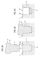
- Fig. 2 is a sectional view showing a mounting hole;
- Fig. 3 is a sectional view which explains the configuration of an electromagnetic valve which is an assembled part;
- Fig. 4 is an enlarged sectional view which explains the configuration of the electromagnetic valve which is the assembled part;
- Figs. 5A to 5C are sectional views which explain a drilling step of a method for producing the vehicle brake hydraulic pressure control unit according to the first embodiment of the invention;
- Figs. 6A to 6C are sectional views which explain an inserting step and a fixing step of the method for producing the vehicle brake hydraulic pressure control unit according to the first embodiment of the invention;
- Figs. 7A to 7D are sectional views which explain in detail the fixing step;
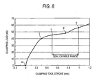
- Fig. 8 is a graph showing a transition of clamping load;
- Fig. 9A is a sectional view which explains the function of the vehicle brake hydraulic pressure control unit according to the first embodiment of the invention;
- Fig. 9B is a sectional view which shows a vehicle brake hydraulic pressure control unit according to a comparison example;
- Fig. 10A is an enlarged sectional view of Fig. 4; and
- Figs. 10B to 10D are enlarged sectional views showing modified examples of the vehicle brake hydraulic pressure control unit according to the first embodiment of the invention.
- Hereinafter, examples of embodiments of the invention will be described in detail by reference to the accompanying drawings. Note that like reference numerals will be given to like elements, so as to omit the repetition of similar descriptions.
- As shown in Fig. 1, a vehicle brake hydraulic pressure control unit U according to a first embodiment of the invention is configured to include a
base body 1 which incorporates therein a brake fluid flow path, a normally openelectromagnetic valve 2 which is an assembled part to be assembled in place in a mountinghole portion 10A formed in thebase body 1 and the like. Note that while the vehicle brake hydraulic pressure control unit U includes a motor 7, anelectronic control unit 8, ahousing 9 and the like in addition to other assembled parts such as a normally closed electromagnetic valve 3, areservoir 4, apump 5 and a pressure sensor 6, since they are similar to those mounted in a conventional one, the detailed description thereof will be omitted here. - The
base body 1 is a member which is substantially a rectangular parallelepiped and which is made of aluminum alloy and incorporates therein a brakefluid flow path 1a (refer to Fig. 2). The mountinghole portion 10 in which the normally openelectromagnetic valve 2 is mounted and a recessedportion 10B which is formed in such a manner as to surround the mountinghole portion 10A are formed in thebase body 1. Furthermore, formed in thebase body 1 are holes in which the normally closed electromagnetic valve 3, thereservoir 4, thepump 5, the pressure switch 6 and the like are mounted, an inlet port 1b to which a piping, not shown, which communicates with a master cylinder (not shown) is connected,outlet ports 1c to which pipings, not shown, which reach wheel brakes are connected, and the like. The respective holes are made to communicate with each other directly or via flow paths, not shown, which are formed in the interior of thebase body 1. - The mounting
hole portion 10A is, as shown in Fig. 2, a bottomed hole which is formed in such a manner as to communicate withflow paths base body 1. In addition, the mountinghole portion 10A includes a cylindrical abutment portion 11 (an inner circumferential sealing surface) which is formed in a lower portion (a deepest portion), acylindrical introducing portion 12 which is formed in a location which lies shallower than theabutment portion 11, a truncated cone-shapedtapered portion 13 which connects theabutment portion 11 with the introducingportion 12, acylindrical holding portion 14 which is formed in a location which lies shallower than the introducingportion 12 and a truncated cone-shaped connectingportion 15 which connects the introducingportion 12 with the holdingportion 14. - A diameter of the mounting
hole portion 10A at the introducingportion 12 is made larger than a diameter at theabutment portion 11, and a diameter of the mountinghole portion 10A at the holdingportion 14 is made larger than the diameter at the introducingportion 12. Namely, the mountinghole portion 10A is formed into a stepped cylindrical shape which sequentially increases in diameter as it extends from a bottom surface 16 (a bottom sealing surface) towards an opening thereof. - One of the
flow paths bottom surface 16, while the other is made to open to the holdingportion 14. Note that since theflow path 1a is made to open to thebottom surface 16, thebottom surface 16 exhibits a circular belt-like shape. - The recessed
portion 10B exhibits the circular belt-like shape when viewed from the top and is formed concentrically with the mountinghole portion 10A. Abottom surface 17 of the recessedportion 10B is formed so that the bottom surface of the mountinghole portion 10A is as a standard. Namely, the recessedportion 10B is not formed by specifying a depth from asurface 1d of thebase body 1 but is formed by specifying a depth from thebottom surface 17 of the recessedportion 10B to thebottom surface 16 of the mountinghole portion 10A. In addition, thebottom surface 16 of the mountinghole portion 10A and thebottom surface 17 of the recessedportion 10B are made parallel to each other. - As shown in Fig. 3, the normally open
electromagnetic valve 2 is configured to include acylindrical valve housing 21 which makes up a stationary core, a firstdust collecting filter 22 mounted in an inner space of thevalve housing 21 in a lower end portion thereof, a valveseat constituting material 23 mounted on an upper side of thedust collecting filter 22 in the inner space of thevalve housing 21, avalve element 24 disposed above the valveseat constituting material 23 in the inner space of thevalve housing 21, areturn spring 25 interposed between the valveseat constituting material 23 and thevalve element 24, amovable core 26 disposed on an upper side of thevalve element 24, acover 27 which covers themovable core 26 and a seconddust collecting filter 28 mounted in such a manner as to surround an outer circumferential surface of thevalve housing 21. In addition, although theelectromagnetic valve 2 protrudes from the mountinghole portion 10A, anelectromagnetic coil 29 for driving theelectromagnetic valve 2 is disposed around the periphery of a protruding part of theelectromagnetic valve 2. - The
valve housing 21 is made of a magnetic material such as iron or iron alloy and includes aninsertion portion 21A which is inserted into the mountinghole portion 10A, alid portion 21B which closes the opening in the mountinghole portion 10A and a protrudingportion 21C which is provided on thelid portion 21B in such a manner as to protrude therefrom. In addition, the inner space of thevalve housing 21 is formed into a stepped cylindrical shape which sequentially increases its diameter as it extends in a downward direction. - As shown in Fig. 4, a lower end portion of the
insertion portion 21A (that is, a lower end portion of the electromagnetic valve 2) includes a press-fit portion 211 which is press fitted in theabutment portion 11 of the mountinghole portion 10A and asmall diameter portion 212 whose diameter is made smaller than the diameter of the press-fit portion 211. - The outside diameter of the press-
fit portion 211 is made equal to or slightly larger than the diameter of the mountinghole portion 10A at theabutment portion 11 or the hole diameter of theabutment portion 11, and when the press-fit portion 211 is press fitted in the abutment portion of the mountinghole portion 10A, an outer circumferential surface of the press-fit portion 211 (an outer circumferential sealing portion) is joined to an inner circumferential surface of theabutment portion 11, whereby the leakage of brake fluid by way of the inner circumferential surface of theabutment portion 11 is prevented. - The
small diameter portion 212 is formed on a lower side of the press-fit portion 211. A lower end surface of the small diameter portion 212 (a lower end sealing portion) is brought into abutment with thebottom surface 16 of the mountinghole portion 10A over the entirety (along the full circumference) thereof. In addition, a location of theinsertion portion 21A which lies further upwards than the press-fit portion 211 (hereinafter, referred to as a "valvecompartment constituting portion 213") face inner circumferential surfaces of the introducingportion 12 and the holdingportion 14 of the mountinghole portion 10A with a gap defined therebetween. A valve compartment V and a throughhole 213a for establishing a communication with theflow path 1a are formed in the valvecompartment constituting portion 213. - In the present invention, the lower end sealing portion of the assembled part (the lower end portion of the small diameter portion 212) hermetically contacts with the bottom sealing surface of the mounting hole portion (a bottom surface 16) to form a lower side sealing portion, and the outer circumferential sealing portion of the assembled part (the outer circumferential surface of the press-fit portion 211) hermetically contacts with the inner circumferential sealing surface of the mounting hole portion (abutment portion 11) to form a circumferential sealing portion.
An annular accommodation space K (hermetic accommodation space) is defined by the lower side sealing portion and the circumferential sealing portion. The accommodation space K is a space which can accommodate chippings produced when the press-fit portion 211 (that is, the lower end portion of the electromagnetic valve 2) is press fitted in the mountinghole portion 10A, and the accommodation space K constitutes a tightly closed space due to the outer circumferential surface of the press-fit portion 211 being joined to the inner circumferential surface of theabutment portion 11 of the mountinghole portion 10A and the lower end surface of the small diameter portion 212 (that is, the lower end surface of the solenoid vale 2) being brought into abutment with thebottom surface 16 of the mountinghole portion 10A. - As shown in Fig. 3, a locking
groove 214 is provided on an outer circumferential surface of thelid portion 21B by setting back a relevant location into the outer circumferential surface along a circumferential direction thereof so that a plastically deformed portion 18 (refer to Fig. 2) that is formed when a hole wall of the mountinghole portion 10A is clamped enters it. In thislid portion 21B, an outside diameter at an upper side of the lockinggroove 214 is made smaller than an outside diameter at a lower side thereof. In this embodiment, a difference in outside diameter of 0.4 mm is provided between the upper side and the lower side of the lockinggroove 214. Note that in the following description, an annular part of thelid portion 21B which lies further downwards than the lockinggroove 214 is referred to as a "lower lid 215" and an annular part thereof which lies further upwards than the lockinggroove 214 is referred to as an "upper lid 216." - The
lower lid 215 lies further upwards than theflow path 1a which is made to open to the holdingportion 14 when theelectromagnetic valve 2 is assembled in place in the mountinghole portion 10A. The outside diameter of thelower lid 215 is made larger than the outside diameters of theinsertion portion 21A and the protrudingportion 21C but is made slightly smaller than the diameter of the mountinghole portion 10A at the holdingportion 14 or the hole diameter of the holdingportion 14. An outer circumferential surface of thelower lid 215 faces an inner circumferential surface of the holdingportion 14 of the mountinghole portion 10A with a slight gap defined therebetween. Note that a lower surface of thelower lid 215 abuts in no case with the hole wall of the mountinghole portion 10A. - The
upper lid 216 protrudes from thebottom surface 17 of the recessedportion 10B when theelectromagnetic valve 2 is assembled in place in the mountinghole portion 10A. In addition, an uppercircumferential edge portion 216a of theupper lid 216 is chamfered. The outside diameter of theupper lid 216 is made smaller than the hole diameter of the holdingportion 14 of the mountinghole portion 10A. Namely, an outer circumferential surface of theupper lid 216 faces the inner circumferential surface of the holdingportion 14 of the mountinghole portion 10A with a gap defined therebetween. - The protruding
portion 21C is a stepped cylindrical shape and an outside diameter of an upper half portion is made smaller than an outside diameter of a lower half portion thereof. Note that the protrudingportion 21C is disposed inside theelectromagnetic coil 29. - The first
dust collecting filter 22 includes acylindrical frame element 221 which is fitted in the valvecompartment constituting portion 213 of thevalve housing 21 and a net-like element 222 which is held on theframe element 221. - The valve
seat constituting material 23 is a cylindrical member which is fitted in the valvecompartment constituting portion 213 of thevalve housing 21 and an outer circumferential surface thereof is joined to an inner circumferential surface of the valvecompartment constituting portion 213. Avalve seat 231 on which thevalve element 24 is seated is provided in the center of an upper surface of the valveseat constituting material 23 in such a manner as to protrude therefrom while surrounding ahollow portion 232. In addition, a throughhole 233 is formed parallel to thehollow portion 232 in a side portion of the valveseat constituting portion 23, and aspherical element 234 which constitutes a one-way valve is disposed at a lower end portion of the throughhole 233. Thespherical element 234 closes the throughhole 233 when a hydraulic pressure on thedust collecting filter 22 side is higher than a hydraulic pressure on the valve compartment V side. To the contrary, when the hydraulic pressure on the valve compartment V side is higher than the hydraulic pressure on thedust collecting filter 22 side, thespherical element 234 opens the throughhole 233. - The
valve element 24 is configured to include aslide member 241 which slides in an interior of the protrudingportion 21C of thevalve housing 21 and aneedle member 242 which is mounted at a lower end of theslide member 241. An upper end portion of theslide member 241 protrudes from an upper end face of thevalve housing 21 in such a state that theelectromagnetic coil 29 is de-energized. - The
return spring 25 is made up of a coil spring and is interposed between the valveseat constituting material 23 and thevalve element 24 in a compressed state, so as to bias thevalve element 24 towards themovable core 26. - The
movable core 26 is made of a magnetic material and moves in an interior of thecover 27 in a vertical direction in such a state that a lower end surface thereof is in abutment with an upper end face of thevalve element 24. Namely, when theelectromagnetic coil 29 is energized, themovable core 26 is attracted by thevalve housing 21 which is the stationary core to thereby be caused to move downwards, so as to push thevalve element 24 downwards. - The
cover 27 exhibits a bottomed cylindrical shape and is placed over an upper portion of the valve housing 21 (or more specifically, an upper half portion of the protrudingportion 21C). In addition, thecover 27 is welded along the full circumference thereof to thereby be fixedly secured to thevalve housing 21. - The second
dust collecting filter 28 is such as to be disposed in such a manner as to surround a throughhole 213a in thevalve housing 21 and is mounted in such a manner as to extend annularly along the valvecompartment constituting portion 213 of theinsertion portion 21A of thevalve housing 21. As shown in Fig. 4, the seconddust collecting filter 28 is configured to include a pair of upper and lowerannular rings like element 282 which is held by theseannular rings - In addition, the
electromagnetic coil 29 shown in Fig. 3 is assembled in place in the cover 9 (refer to Fig. 1) and is then mounted annularly on thevalve housing 21 and the protrudingportion 21C when thehousing 9 is mounted on thebase body 1. - The
electromagnetic valve 2, which is configured as has been described heretofore, is closed when theelectromagnetic coil 29 is energized and is opened when theelectromagnetic coil 29 is de-energized. Namely, when theelectromagnetic coil 29 is energized based on a command from the electronic control unit 8 (refer to Fig. 1), themovable core 26 is attracted by thevalve housing 21, which is the stationary core, and is then caused to move downwards. Along with this, thevalve element 24 moves downwards to be seated on thevalve seat 231 of the valveseat constituting material 23 at the lower end portion (the needle member 242) thereof, so as to close thehollow portion 232. In addition, when theelectromagnetic coil 29 is de-energized, thevalve element 24 and themovable core 26 are pushed back in an upward direction by virtue of the biasing force of thereturn spring 25, whereby the lower end portion (the needle member 242) of thevalve element 24 moves apart from thevalve seat 231, so as to open thehollow portion 232. - Referring to Figs. 5 to 7, a method for producing the vehicle brake hydraulic pressure control unit U will be described.
Firstly, as shown in Fig. 5A, a mountinghole portion 10A and a recessedportion 10B are formed in abase body 1 which is formed into a predetermined shape (a drilling step). The mounting hole portion 101a and the recessedportion 10B are formed integrally through a single step by employing a stepped drilling tool D. The drilling tool D includes a lower stepped portion D1 having a cutting blade for forming the mountinghole portion 10A and an upper stepped portion D2 having a cutting blade for forming the recessedportion 10B. Then, as shown in Figs. 5B and 5C, when the drilling tool D is pressed against a surface of thebase body 1 while rotating the drilling tool D, the mountinghole portion 10A is formed by the lower stepped portion D1. Following this, the recessedportion 10B is formed by the upper stepped portion D2. - In addition, although the illustration of forming them is omitted here, before and after the operations described above, holes (bores) for mounting the normally closed electromagnetic valve 3, the
reservoir 4, the pump 5 (refer to Fig. 1) and the like are formed in appropriate locations in thebase body 1, and brakefluid flow paths 1a and the like are formed in an interior of thebase body 1 by cutting surfaces of thebase body 1. - Next, as shown in Figs. 6A and 6B, the normally open
electromagnetic valve 2 is inserted into the mountinghole portion 10A, and the lower end surface thereof is brought into abutment with thebottom surface 16 of the mountinghole portion 10A (an inserting step). Namely, as shown in Fig. 4, the press-fit portion 211 of theelectromagnetic valve 2 is press fitted in theabutment portion 11 of the mountinghole portion 10A, and the full circumference of the lower end surface of thesmall diameter portion 212 is brought into abutment with thebottom surface 16 of the mountinghole portion 10A while joining the outer circumferential surface of the press-fit portion 211 to the inner circumferential surface of theabutment portion 11. In this embodiment, since the taperedportion 13 formed between theabutment portion 11 and the introducingportion 12 of the mountinghole portion 10A and thesmall diameter portion 211 formed at the lower end portion of theelectromagnetic valve 2 both function as a "guide" for theelectromagnetic valve 2, the press-fit portion 211 of theelectromagnetic valve 2 can be press fitted in theabutment portion 11 of the mountinghole portion 10A in a simple and ensured fashion. - According to this embodiment, the accommodation space K is defined by the outer circumferential surface of the
small diameter portion 212 and the inner circumferential surface of theabutment portion 11 of the mountinghole portion 10A when the press-fit portion 211 of theelectromagnetic valve 2 is press fitted in theabutment portion 11 of the mountinghole portion 10A and the lower end surface of thesmall diameter portion 212 is brought into abutment with thebottom surface 16 of the mountinghole portion 10A. Therefore, chippings or the like which are produced in association with the press fitting of the electromagnetic valve are accommodated within the accommodation space K so defined. Furthermore, the inserting position of theelectromagnetic valve 2 comes to be restricted vertically (in a depth direction) as well as radially. - Following this, the hole wall of the mounting
hole portion 10A is clamped based on the inserting position of theelectromagnetic valve 2, so as to fix theelectromagnetic valve 2 in place (a fixing step). Namely, as shown in Fig. 6C, a clamping jig E which exhibits a bottomed cylindrical shape is pressed against thebottom surface 17 of the recessedportion 10B while maintaining the state in which the lower end surface is in abutment with thebottom surface 16 of the mountinghole portion 10A, so that the hole wall of the mountinghole portion 10A is pressed downwards (towards the bottom surface 16) by the clamping jig E so as to form a plastically deformed portion 18 (refer to Fig. 4). The plasticallydeformed portion 18 so formed is then made to be locked in the locking groove 214 (refer to Fig. 4) formed on the outer circumferential surface of theelectromagnetic valve 2, whereby theelectromagnetic valve 2 is clamped and fixed in place in the mountinghole portion 10A. By pressing thebottom surface 17 of the recessedportion 10B towards thebottom surface 16 of the mountinghole portion 10A after theelectromagnetic valve 2 has been inserted into the mountinghole portion 10A so as to form the plasticallydeformed portion 18, theelectromagnetic valve 2 is held in the mountinghole portion 10A in such a manner as not to be dislocated therefrom, and also is sealed fluid tightly by virtue of a residual radial stress in the plasticallydeformed portion 18. In addition, in this embodiment, the inserting position of the electromagnetic valve is restricted by joining the outer circumferential surface of the lower end portion of theelectromagnetic valve 2 to the inner circumferential surface of theabutment portion 11 of the mountinghole portion 10A and bringing the whole circumference of the lower end surface of theelectromagnetic valve 2 into abutment with thebottom surface 16 of the mountinghole portion 10A and the hole wall of the holdingportion 14 of the mountinghole portion 10A which does not contribute to the positioning of theelectromagnetic valve 2 is clamped while the inserting position is maintained. Accordingly, theelectromagnetic valve 2 is made difficult to be inclined when theelectromagnetic valve 2 is fixed. - Referring to Figs. 7A to 7D, the fixing step will be described in greater detail. Firstly, as shown in Fig. 7A, a full circumference of a lower end surface of the clamping jig E is brought into abutment with an inner circumferential edge of the
bottom surface 17 of therecessedportion 10B. Note that while an inside diameter of the clamping jig E is substantially the same as an outside diameter of theupper lid 216 of theelectromagnetic valve 2, since the uppercircumferential edge portion 216a of theupper lid 216 of theelectromagnetic valve 2 is chamfered, the clamping jig E can be positioned in a smooth fashion. Namely, when the clamping jig E is placed over theelectromagnetic valve 2, since the lower end portion of the clamping jig E is guided by thecircumferential edge portion 216a, the full circumference of the lower end surface of the clamping jig E can be brought into abutment with thebottom surface 17 of the recessedportion 10B in an ensured fashion. - Next, a downward clamping load is applied to the clamping jig E ("a" → "b" in a graph shown in Fig. 8), and the lower end portion of the clamping jig E is, as shown in Fig. 7B, caused to sink into the
bottom surface 17 of the recessedportion 10B. Note that since the gap is defined between the inner circumferential surface of the holdingportion 14 of the mountinghole portion 10A and the outer circumferential surface of theupper lid 216 of the electromagnetic valve 2 (refer to Fig. 7A), when the lower end portion of the clamping jig E is caused to sink into thebottom surface 17 of the recessedportion 10B, the hole wall of the mountinghole portion 10A at the holdingportion 14 is plastically deformed (plastically flows) towards theupper lid 216 of theelectromagnetic valve 2, whereby the full circumference of the inner circumferential surface of the holding portion 14 (refer to Fig. 3) of the mountinghole portion 10A comes to be joined to the outer circumferential surface of theupper lid 216 of theelectromagnetic valve 2. Incidentally, since the gap is defined between the inner circumferential surface of the holdingportion 14 of the mountinghole portion 10A and the outer circumferential surface of theupper lid 216 of theelectromagnetic valve 2, the hole wall of the mountinghole portion 10A can be plastically deformed with a small clamping load. - When the clamping load is increased ("b" → "c" in the graph shown in Fig. 8), the lower end portion of the clamping jig E is made to sink deeper as shown in Fig. 7C. In association with this, the hole wall of the mounting
hole portion 10A is pushed out over an upper side of thelower lid 215 of theelectromagnetic valve 2 so as to press hold aboundary portion 217 between thelower lid 215 and the lockinggroove 214 along the full circumference thereof. In addition, at this point in time, theelectromagnetic valve 2 is locked by the plasticallydeformed portion 18 in such a manner as not to be dislocated from the mountinghole portion 10A and a seal is established between the holdingportion 14 of the mountinghole portion 10A and thelower lid 215 of theelectromagnetic valve 2 by virtue of the residual radial stress in the plasticallydeformed portion 18. - When the clamping force is increased further ("c" → "d" in the graph shown in Fig. 8), the plastic deformation (plastic flowing) is developed further by the hole wall of the mounting
hole portion 10A, as shown in Fig. 7D, the plasticallydeformed portion 18 formed on the hole wall of the mountinghole portion 10A comes to enter the lockinggroove 214 on theelectromagnetic valve 2. - In addition, when the clamping load is increased far more ("d" → "e" in the graph shown in Fig. 8), although an illustration thereof is omitted, the whole of the locking
groove 214 of theelectromagnetic valve 2 is filled with the plasticallydeformed portion 18 of the mountinghole portion 10A. Thus, in the vehicle brake hydraulic pressure control unit U, the stroke and clamping load of the clamping jig E are controlled so that they fall within ranges defined from "c" to "e" shown in Fig. 8, the aforesaid location can be sealed. - Before or after the normally open
electromagnetic valve 2 is assembled, when the normally closed electromagnetic valve 3, thereservoir 4, thepump 5, the pressure sensor 6, the motor 7 and the like are, as shown in Fig. 1, assembled on to thebase body 1 and thehousing 9 is assembled further to cover theelectromagnetic valves 2, 3, the vehicle brake hydraulic pressure control unit U is then completed. - According to the vehicle brake hydraulic pressure control unit U that has been described heretofore, even in the event that chippings are produced when press fitting the
electromagnetic valve 2 in the mountinghole portion 10A in thebase body 1, since the chippings so produced are accommodated in the accommodation space K, the mixing of the chippings into the brake fluid can be prevented. Namely, an increase in sliding resistance at the sliding portion of the vehicle brake hydraulic pressure control unit U can be suppressed, and furthermore, the wear of the seal portion can be prevented. - Furthermore, in the vehicle brake hydraulic pressure control unit U, the recessed
portion 10B is formed along the periphery of the mountinghole portion 10A, thebottom surface 17 of the recessedportion 10B is formed so that thebottom surface 16 of the mountinghole portion 10A is as a standard, and the lower end surface of theelectromagnetic valve 2 is brought into abutment with thebottom surface 16 of the mountinghole portion 10A. Accordingly, deviation in magnitude of the clamping load is made difficult to occur when theelectromagnetic valve 2 is fixed in place in the mountinghole portion 10A. Namely, although the stroke of the clamping jig E is dependent on the distance from the surface of the base body 1 (in this embodiment, thebottom surface 17 of the recessedportion 10B) to the lockinggroove 214 of theelectromagnetic valve 2, in this vehicle brake hydraulic pressure control unit U, deviation in depth of the mountinghole portion 10A (namely, a distance from thebottom surface 16 of the mountinghole portion 10A to thebottom surface 17 of the recessedportion 10B) is made difficult to occur due to thebottom surface 17 of the recessedportion 10B being formed based on thebottom surface 16 of the mountinghole portion 10A. Furthermore, deviation in amount in which theelectromagnetic valve 2 is inserted is made difficult to occur due to the lower end surface of theelectromagnetic valve 2 being brought into abutment with thebottom surface 16 of the mountinghole portion 10A. Consequently, deviation in distance from thebottom surface 17 of the recessedportion 10B to the lockinggroove 214 of theelectromagnetic valve 2 is also made difficult to occur, As a result of this, deviation in amount in which the plasticallydeformed portion 18 is filled in the lockingportion 214 is made difficult to occur. - In particular, in this embodiment, since the mounting
hole portion 10A and the recessedportion 10B are formed integrally by the same drilling tool D, deviation in depth of the mountinghole portion 10A is decreased to an extremely low level, and deviation in distance from thebottom surface 17 of the recessedportion 10B to the lockinggroove 214 of the electromagnetic valve becomes dependent only on the production accuracy of theelectromagnetic valve 2. Namely, according to the vehicle brake hydraulic pressure control unit U, the deviation in distance from thebottom surface 17 of the recessedportion 10B to the lockinggroove 214 of theelectromagnetic valve 2 becomes extremely small, and consequently, deviation in stroke of the clamping jig E also becomes extremely small. - In addition, in the vehicle brake hydraulic pressure control unit U, the outside diameter of the
electromagnetic valve 2 at the upper side of the lockinggroove 214 is made smaller than the outside diameter of theelectromagnetic valve 2 at the lower side of the lockinggroove 214. Therefore, the hole diameter of the mountinghole portion 10A after plastic deformation (clamping) becomes smaller at the upper side than at the lower side of the lockinggroove 214. Consequently, when force is applied to theelectromagnetic valve 2 in a direction in which theelectromagnetic valve 2 is pushed out from the mountinghole portion 10A, a shear fracture plane is, as shown in Fig. 9A, formed in such a manner as to rise obliquely upwards from the lower outer circumferential edge of the locking groove 214 (theboundary portion 217 between thelower lid 215 and the locking groove 214). In the event that the outside diameter of theelectromagnetic valve 2 becomes the same at an upper side as at a lower side of a locking groove 214' as shown in Fig. 9B, a shear fracture distance S2 becomes equal to the groove width of the locking groove 214'. However, as shown in Fig. 9A, in the event that the hole diameter at the upper side of the lockinggroove 214 is made smaller than the hole diameter at the lower side thereof, a shear fracture distance S1 becomes equal to or larger than the groove width of the lockinggroove 214. Therefore, even in the event that the groove width of the lockinggroove 214 is made smaller than the groove width of the locking groove 214', an assembling strength (a resisting force against the push-out force by the brake hydraulic pressure) which is equal to that produced in the case shown in Fig. 9B can be secured. - In addition, in the vehicle brake hydraulic pressure control unit U, since the gap is defined at the upper side of the locking
groove 214, the plasticallydeformed portion 18 can be formed with a small clamping load. Hence, a reduction in size of the production equipment can be attained. - Note that there will be no problem even in the event that the configuration of the vehicle brake hydraulic pressure control unit is modified as required. For example, while in the embodiment, the lower end surface of the
electromagnetic valve 2 is formed into the flat shape so as to be brought into abutment with thebottom surface 16 of the mountinghole portion 10A, a lower end surface of anelectromagnetic valve 2 may be formed into a shape which is convex relative to abottom surface 16 of a mountinghole portion 10A as shown in Fig. 10B, so as to be made to sink into thebottom surface 16 of the mountinghole portion 10A. By adopting this configuration, since the contact surface pressure between the lower end surface of theelectromagnetic valve 2 and thebottom surface 16 of the mountinghole portion 10A is increased, the closeness of the accommodation space K is increased further. - In addition, as shown in Fig. 10C, a
circumferential surface groove 11a may be provided on an inner circumferential surface of anabutment portion 11 of a mountinghole portion 10A by setting back a relevant location into the inner circumferential surface along the circumferential direction, so as to form an accommodation space K by making use of thecircumferential surface groove 11a. Namely, part of theabutment portion 11 of the mountinghole portion 10A may be expanded diametrically so as to form the accommodation space K. In addition, while in anelectromagnetic valve 2 in Fig. 10C, a small diameter portion 212 (refer to Fig. 4) is omitted, the accommodation space K is secured by providing thecircumferential surface groove 11a. Since working on anelectromagnetic valve 2 can be omitted or simplified in the event that an accommodation space K is formed by working on a mountinghole portion 10A, a conventional electromagnetic valve can be carried over for assembly into the mountinghole portion 10A so worked. In addition, in the event that working on anelectromagnetic valve 2 is simplified, an accommodation space K can be secured without reducing the strength of avalve housing 21 or the like of theelectromagnetic valve 2. - Furthermore, as shown in Fig. 10D, a
bottom surface groove 16a may be provided on abottom surface 16 of a mountinghole portion 10A by setting back a relevant location into thebottom surface 16 along an outer circumference thereof, so as to form an accommodation space K by making use of thebottom surface groove 16a so provided. In addition, thebottom surface groove 16a can be formed by a candle type drill, thebottom surface groove 16a can be formed more simply and inexpensively than thecircumferential surface groove 11a shown in Fig. 10C. - While the invention has been described in connection with the exemplary embodiments, it will be obvious to those skilled in the art that various changes and modification may be made therein without departing from the present invention defined in the appended claims.
Furthermore, according to a third aspect of the invention, as set forth in the second aspect of the invention, it is more preferable that
the small diameter portion is formed on a lower side of the press-fit portion, and
a lower end surface of the small diameter portion is brought into abutment with the bottom sealing surface of the mounting hole portion.
By adopting these configurations, when press fitting the lower end portion of the assembled part in the abutment portion of the mounting hole portion, the small diameter portion functions as a "guide" and therefore, the press fitting work is facilitated.
Claims (8)
- A vehicle brake hydraulic pressure control unit comprising:a base body comprising:a brake fluid flow path; anda mounting hole portion comprising:a bottom sealing surface formed on a bottom surface thereof; andan inner circumferential sealing surface formed on an inner circumferential surface thereof; andan assembled part which is assembled into the mounting hole portion so as to communicate with the flow path, the assembled part comprising:a lower end sealing portion formed on a lower end surface thereof and hermetically contacting with the bottom sealing surface of the mounting hole portion to form a lower side sealing portion; andan outer circumferential sealing portion formed on an outer circumferential surface thereof and hermetically contacting with the inner circumferential sealing surface of the mounting hole portion to form a circumferential sealing portion, whereina hermetic accommodation space is defined by the lower side sealing portion and the circumferential sealing portion.
- The vehicle brake hydraulic pressure control unit as set forth in Claim 1, wherein
a lower end portion of the assembled part comprises:a press-fit portion which is press fitted in the inner circumferential sealing surface of the mounting hole portion; anda small diameter portion whose diameter is smaller than a diameter of the press-fit portion, andthe accommodation space is further defined by an outer circumferential surface of the small diameter portion and an inner circumferential surface of the mounting hole portion. - The vehicle brake hydraulic pressure control unit as set forth in Claim 2, wherein
the small diameter portion is formed on a lower side of the press-fit portion, and
a lower end surface of the small diameter portion is brought into abutment with the bottom sealing surface of the mounting hole portion. - The vehicle brake hydraulic pressure control unit as set forth in Claim 1, wherein
a circumferential groove is provided on the inner circumferential surface of the mounting hole portion along a circumferential direction, and
the accommodation space is further defined by the circumferential groove. - The vehicle brake hydraulic pressure control unit as set forth in Claim 1, wherein
a bottom groove is provided on the bottom surface of the mounting hole portion along an outer circumference of the bottom surface, and wherein
the accommodation space is further defined by the bottom groove. - The vehicle brake hydraulic pressure control unit as set forth in Claims 1, wherein
the lower end surface of the assembled part is formed into a shape which protrudes towards the bottom surface of the mounting hole portion. - The vehicle brake hydraulic pressure control unit as set forth in Claim 1, wherein
the mounting hole portion comprises:an introducing portion which is formed at an upper side of the inner circumferential sealing surface; anda tapered portion which connects the inner circumferential sealing surface with the introducing portion, anda diameter of the introducing portion is made larger than a diameter of the inner circumferential sealing surface. - The vehicle brake hydraulic pressure control unit as set forth in Claim 1, wherein
a locking groove for a plastically deformed portion formed when a hole wall of the mounting hole portion is clamped to enter is formed on the outer circumferential surface of the assembled part, and
an outside diameter of the assembled part at an upper side of the locking groove is made smaller than an outside diameter of assembled part at a lower side of the locking groove.
Applications Claiming Priority (1)
| Application Number | Priority Date | Filing Date | Title |
|---|---|---|---|
| JP2006280420A JP4276673B2 (en) | 2006-10-13 | 2006-10-13 | Brake hydraulic pressure control device for vehicles |
Publications (3)
| Publication Number | Publication Date |
|---|---|
| EP1911646A2 true EP1911646A2 (en) | 2008-04-16 |
| EP1911646A3 EP1911646A3 (en) | 2009-10-07 |
| EP1911646B1 EP1911646B1 (en) | 2013-03-27 |
Family
ID=38948373
Family Applications (1)
| Application Number | Title | Priority Date | Filing Date |
|---|---|---|---|
| EP07020065A Ceased EP1911646B1 (en) | 2006-10-13 | 2007-10-12 | Vehicle brake hydraulic pressure control unit |
Country Status (4)
| Country | Link |
|---|---|
| US (1) | US8141959B2 (en) |
| EP (1) | EP1911646B1 (en) |
| JP (1) | JP4276673B2 (en) |
| CN (1) | CN101161521B (en) |
Cited By (1)
| Publication number | Priority date | Publication date | Assignee | Title |
|---|---|---|---|---|
| WO2011076484A1 (en) * | 2009-12-23 | 2011-06-30 | Robert Bosch Gmbh | Magnetic valve device |
Families Citing this family (15)
| Publication number | Priority date | Publication date | Assignee | Title |
|---|---|---|---|---|
| JP4276674B2 (en) * | 2006-10-13 | 2009-06-10 | 日信工業株式会社 | Brake hydraulic pressure control device for vehicle and manufacturing method of brake hydraulic pressure control device for vehicle |
| JP5193272B2 (en) * | 2010-11-25 | 2013-05-08 | 日信工業株式会社 | Hydraulic pressure control device and manufacturing method thereof |
| JP5478571B2 (en) * | 2011-08-03 | 2014-04-23 | 日本電信電話株式会社 | Disaster prevention information distribution method and apparatus |
| KR101294674B1 (en) * | 2011-11-02 | 2013-08-09 | 주식회사 만도 | Solenoid valve for brake system |
| US9616866B2 (en) * | 2013-01-25 | 2017-04-11 | Autoliv Nissin Brake Systems Japan Co., Ltd. | Vehicular brake hydraulic pressure control apparatus |
| JP2015160464A (en) * | 2014-02-26 | 2015-09-07 | 株式会社デンソー | Actuator for brake fluid pressure control |
| CN105523026B (en) * | 2014-10-21 | 2018-09-28 | 株式会社万都 | Integrated power brake system |
| KR20160080899A (en) * | 2014-12-29 | 2016-07-08 | 주식회사 만도 | Electric intergrated hydraulic brake |
| JP2018090071A (en) * | 2016-12-02 | 2018-06-14 | ローベルト ボッシュ ゲゼルシャフト ミット ベシュレンクテル ハフツング | Brake fluid pressure control device, motorcycle brake system, and brake fluid pressure control device manufacturing method |
| JP2019006347A (en) * | 2017-06-28 | 2019-01-17 | ローベルト ボッシュ ゲゼルシャフト ミット ベシュレンクテル ハフツング | Fluid pressure control apparatus, brake system for saddle-riding type vehicle, and saddle-riding type vehicle |
| DE102017213885A1 (en) * | 2017-08-09 | 2019-02-14 | Robert Bosch Gmbh | Pressure medium unit, in particular for adjusting and / or regulating a brake pressure in an electronic slip-controllable vehicle brake system and hat-shaped filter element |
| KR102079023B1 (en) * | 2017-11-06 | 2020-02-19 | 주식회사 만도 | Integrated type solenoid valve and brake system using the same |
| CN110332179B (en) * | 2019-07-11 | 2021-09-17 | 陶象余 | Supporting hydraulic pressure station of grouting pump |
| DE102019212353A1 (en) * | 2019-08-19 | 2021-02-25 | Robert Bosch Gmbh | Hydraulic block for a hydraulic unit of an external hydraulic vehicle brake system |
| CN112516670A (en) * | 2020-10-27 | 2021-03-19 | 宁波拓普集团股份有限公司 | Solenoid valve ring filter screen for automobile brake and mounting structure thereof |
Citations (4)
| Publication number | Priority date | Publication date | Assignee | Title |
|---|---|---|---|---|
| JPH1137316A (en) | 1997-07-18 | 1999-02-12 | Unisia Jecs Corp | Plug components for hydraulic equipment |
| US5984263A (en) | 1996-01-12 | 1999-11-16 | Nisshinbo Industries Inc. | Solenoid valve device |
| JPH11351151A (en) | 1998-06-12 | 1999-12-21 | Nisshinbo Ind Inc | Fixing member mounting method for hydraulic pump and housing structure |
| US6318703B1 (en) | 1997-01-14 | 2001-11-20 | Continental Teves Ag & Co., Ohg | Electromagnetic valve and process for setting the stroke of an electromagnetic valve |
Family Cites Families (10)
| Publication number | Priority date | Publication date | Assignee | Title |
|---|---|---|---|---|
| US5184804A (en) * | 1992-05-12 | 1993-02-09 | Siemens Automotive L.P. | Contamination containment device |
| FR2692876B1 (en) | 1992-06-25 | 1996-03-08 | Heidelberger Druckmasch Ag | AUTOMATIC DEVICE FOR CAPTURING A RIPPED STRIP OF PAPER. |
| GB9510177D0 (en) * | 1995-05-19 | 1995-07-12 | Lucas Ind Plc | Improvements in and relating to electronic braking systems |
| DE19535368C2 (en) * | 1995-09-25 | 1998-04-30 | Bosch Gmbh Robert | Fuel injection device for internal combustion engines |
| JP4269477B2 (en) | 2000-03-28 | 2009-05-27 | 株式会社デンソー | Electromagnetic valve assembly structure and brake device using the same |
| JP3934882B2 (en) | 2001-03-30 | 2007-06-20 | 株式会社日立製作所 | Plunger pump |
| JP3742354B2 (en) * | 2001-04-25 | 2006-02-01 | 株式会社日立製作所 | Brake fluid pressure control unit for in-vehicle devices |
| JP4563095B2 (en) | 2001-04-25 | 2010-10-13 | 日立オートモティブシステムズ株式会社 | Brake fluid pressure control unit |
| US6846408B2 (en) * | 2003-03-07 | 2005-01-25 | Kelsey-Hayes Company | Filter assembly for a control valve in a vehicular brake system |
| JP2007055521A (en) * | 2005-08-26 | 2007-03-08 | Advics:Kk | Solenoid valve for brake control |
-
2006
- 2006-10-13 JP JP2006280420A patent/JP4276673B2/en active Active
-
2007
- 2007-10-11 US US11/870,930 patent/US8141959B2/en active Active
- 2007-10-12 EP EP07020065A patent/EP1911646B1/en not_active Ceased
- 2007-10-15 CN CN200710152467.8A patent/CN101161521B/en not_active Expired - Fee Related
Patent Citations (4)
| Publication number | Priority date | Publication date | Assignee | Title |
|---|---|---|---|---|
| US5984263A (en) | 1996-01-12 | 1999-11-16 | Nisshinbo Industries Inc. | Solenoid valve device |
| US6318703B1 (en) | 1997-01-14 | 2001-11-20 | Continental Teves Ag & Co., Ohg | Electromagnetic valve and process for setting the stroke of an electromagnetic valve |
| JPH1137316A (en) | 1997-07-18 | 1999-02-12 | Unisia Jecs Corp | Plug components for hydraulic equipment |
| JPH11351151A (en) | 1998-06-12 | 1999-12-21 | Nisshinbo Ind Inc | Fixing member mounting method for hydraulic pump and housing structure |
Cited By (2)
| Publication number | Priority date | Publication date | Assignee | Title |
|---|---|---|---|---|
| WO2011076484A1 (en) * | 2009-12-23 | 2011-06-30 | Robert Bosch Gmbh | Magnetic valve device |
| US10184584B2 (en) | 2009-12-23 | 2019-01-22 | Robert Bosch Gmbh | Magnetic valve device |
Also Published As
| Publication number | Publication date |
|---|---|
| CN101161521A (en) | 2008-04-16 |
| CN101161521B (en) | 2015-03-25 |
| EP1911646A3 (en) | 2009-10-07 |
| US20080088176A1 (en) | 2008-04-17 |
| EP1911646B1 (en) | 2013-03-27 |
| JP2008094321A (en) | 2008-04-24 |
| JP4276673B2 (en) | 2009-06-10 |
| US8141959B2 (en) | 2012-03-27 |
Similar Documents
| Publication | Publication Date | Title |
|---|---|---|
| EP1911646B1 (en) | Vehicle brake hydraulic pressure control unit | |
| EP1911647B1 (en) | Vehicle brake hydraulic pressure control unit and method for producing the same | |
| US7611125B2 (en) | Valve and method for producing a valve | |
| CN101267970B (en) | The electromagnetic valve | |
| US4558498A (en) | Process for the manufacture of solenoid operated valve | |
| CN102686464B (en) | Valve module, especially for automobile braking system electromagnetic valve and manufacture the method for this valve module | |
| CN114096774B (en) | Valve, device for regulating pressure of flow medium using the valve, and device for fixing the valve in a transmission component | |
| JP2002510021A (en) | Solenoid valve | |
| JP2002502771A (en) | Pressure control valve | |
| JP5487836B2 (en) | Hydraulic device with solenoid valve | |
| KR100449145B1 (en) | Electromagnetic valve | |
| JP3142680B2 (en) | Solenoid valve | |
| JP2008273507A (en) | Brake hydraulic pressure control device for vehicles | |
| JP4891754B2 (en) | Manufacturing method of vehicle brake hydraulic pressure control device and vehicle brake hydraulic pressure control device | |
| WO2017064898A1 (en) | Fluid pressure device and method for manufacturing same | |
| US10471943B2 (en) | Vehicle brake hydraulic pressure control apparatus and method for manufacturing the same | |
| JP2008111355A (en) | Reciprocating pump | |
| JP4787729B2 (en) | Brake hydraulic pressure control device for vehicle and manufacturing method thereof | |
| JP3119274B2 (en) | Solenoid valve and manufacturing method thereof | |
| CN102650329A (en) | Cylinder device and producing method thereof | |
| JP2004340324A (en) | solenoid valve | |
| JP2011021532A (en) | Solenoid pump | |
| JP2000046221A (en) | Solenoid valve device | |
| KR20260027140A (en) | poppet valve | |
| JPH1061810A (en) | Solenoid valve |
Legal Events
| Date | Code | Title | Description |
|---|---|---|---|
| PUAI | Public reference made under article 153(3) epc to a published international application that has entered the european phase |
Free format text: ORIGINAL CODE: 0009012 |
|
| AK | Designated contracting states |
Kind code of ref document: A2 Designated state(s): AT BE BG CH CY CZ DE DK EE ES FI FR GB GR HU IE IS IT LI LT LU LV MC MT NL PL PT RO SE SI SK TR |
|
| AX | Request for extension of the european patent |
Extension state: AL BA HR MK RS |
|
| PUAL | Search report despatched |
Free format text: ORIGINAL CODE: 0009013 |
|
| AK | Designated contracting states |
Kind code of ref document: A3 Designated state(s): AT BE BG CH CY CZ DE DK EE ES FI FR GB GR HU IE IS IT LI LT LU LV MC MT NL PL PT RO SE SI SK TR |
|
| AX | Request for extension of the european patent |
Extension state: AL BA HR MK RS |
|
| 17P | Request for examination filed |
Effective date: 20100407 |
|
| AKX | Designation fees paid |
Designated state(s): DE GB |
|
| 17Q | First examination report despatched |
Effective date: 20101203 |
|
| GRAP | Despatch of communication of intention to grant a patent |
Free format text: ORIGINAL CODE: EPIDOSNIGR1 |
|
| RAP1 | Party data changed (applicant data changed or rights of an application transferred) |
Owner name: NISSIN KOGYO CO., LTD. |
|
| GRAS | Grant fee paid |
Free format text: ORIGINAL CODE: EPIDOSNIGR3 |
|
| GRAA | (expected) grant |
Free format text: ORIGINAL CODE: 0009210 |
|
| RIN1 | Information on inventor provided before grant (corrected) |
Inventor name: OTA, KAZUHIRO C/O NISSIN KOGYO CO., LTD. |
|
| RAP1 | Party data changed (applicant data changed or rights of an application transferred) |
Owner name: NISSIN KOGYO CO., LTD. |
|
| AK | Designated contracting states |
Kind code of ref document: B1 Designated state(s): DE GB |
|
| REG | Reference to a national code |
Ref country code: GB Ref legal event code: FG4D |
|
| REG | Reference to a national code |
Ref country code: DE Ref legal event code: R096 Ref document number: 602007029284 Country of ref document: DE Effective date: 20130523 |
|
| PLBE | No opposition filed within time limit |
Free format text: ORIGINAL CODE: 0009261 |
|
| STAA | Information on the status of an ep patent application or granted ep patent |
Free format text: STATUS: NO OPPOSITION FILED WITHIN TIME LIMIT |
|
| 26N | No opposition filed |
Effective date: 20140103 |
|
| REG | Reference to a national code |
Ref country code: DE Ref legal event code: R097 Ref document number: 602007029284 Country of ref document: DE Effective date: 20140103 |
|
| REG | Reference to a national code |
Ref country code: DE Ref legal event code: R082 Ref document number: 602007029284 Country of ref document: DE Representative=s name: HOFFMANN - EITLE PATENT- UND RECHTSANWAELTE PA, DE Ref country code: DE Ref legal event code: R081 Ref document number: 602007029284 Country of ref document: DE Owner name: AUTOLIV NISSIN BRAKE SYSTEMS JAPAN CO., LTD., , JP Free format text: FORMER OWNER: NISSIN KOGYO CO., LTD., UEDA, NAGANO, JP |
|
| REG | Reference to a national code |
Ref country code: GB Ref legal event code: 732E Free format text: REGISTERED BETWEEN 20160811 AND 20160817 |
|
| PGFP | Annual fee paid to national office [announced via postgrant information from national office to epo] |
Ref country code: GB Payment date: 20231025 Year of fee payment: 17 |
|
| PGFP | Annual fee paid to national office [announced via postgrant information from national office to epo] |
Ref country code: DE Payment date: 20231018 Year of fee payment: 17 |
|
| REG | Reference to a national code |
Ref country code: DE Ref legal event code: R119 Ref document number: 602007029284 Country of ref document: DE |
|
| GBPC | Gb: european patent ceased through non-payment of renewal fee |
Effective date: 20241012 |
|
| PG25 | Lapsed in a contracting state [announced via postgrant information from national office to epo] |
Ref country code: DE Free format text: LAPSE BECAUSE OF NON-PAYMENT OF DUE FEES Effective date: 20250501 |
|
| PG25 | Lapsed in a contracting state [announced via postgrant information from national office to epo] |
Ref country code: GB Free format text: LAPSE BECAUSE OF NON-PAYMENT OF DUE FEES Effective date: 20241012 |