EP1911567A1 - Continuous transverse welding assembly for flow-pack packaging machines - Google Patents
Continuous transverse welding assembly for flow-pack packaging machines Download PDFInfo
- Publication number
- EP1911567A1 EP1911567A1 EP06425695A EP06425695A EP1911567A1 EP 1911567 A1 EP1911567 A1 EP 1911567A1 EP 06425695 A EP06425695 A EP 06425695A EP 06425695 A EP06425695 A EP 06425695A EP 1911567 A1 EP1911567 A1 EP 1911567A1
- Authority
- EP
- European Patent Office
- Prior art keywords
- welding
- operating position
- welding assembly
- axis
- counterblade
- Prior art date
- Legal status (The legal status is an assumption and is not a legal conclusion. Google has not performed a legal analysis and makes no representation as to the accuracy of the status listed.)
- Withdrawn
Links
- 238000003466 welding Methods 0.000 title claims abstract description 66
- 238000004806 packaging method and process Methods 0.000 title claims abstract description 11
- 239000005022 packaging material Substances 0.000 claims abstract description 26
- 238000005520 cutting process Methods 0.000 claims abstract description 23
- 230000000694 effects Effects 0.000 claims abstract description 5
- 238000006073 displacement reaction Methods 0.000 claims description 5
- 238000005096 rolling process Methods 0.000 description 6
- 238000003491 array Methods 0.000 description 4
- 230000006835 compression Effects 0.000 description 3
- 238000007906 compression Methods 0.000 description 3
- 239000000463 material Substances 0.000 description 2
- 238000011144 upstream manufacturing Methods 0.000 description 2
- 238000005452 bending Methods 0.000 description 1
- 230000005540 biological transmission Effects 0.000 description 1
- 238000004519 manufacturing process Methods 0.000 description 1
- 230000010355 oscillation Effects 0.000 description 1
- 230000035515 penetration Effects 0.000 description 1
- 239000000523 sample Substances 0.000 description 1
- 238000007789 sealing Methods 0.000 description 1
- 125000006850 spacer group Chemical group 0.000 description 1
Images




Classifications
-
- B—PERFORMING OPERATIONS; TRANSPORTING
- B65—CONVEYING; PACKING; STORING; HANDLING THIN OR FILAMENTARY MATERIAL
- B65B—MACHINES, APPARATUS OR DEVICES FOR, OR METHODS OF, PACKAGING ARTICLES OR MATERIALS; UNPACKING
- B65B51/00—Devices for, or methods of, sealing or securing package folds or closures; Devices for gathering or twisting wrappers, or necks of bags
- B65B51/10—Applying or generating heat or pressure or combinations thereof
- B65B51/26—Devices specially adapted for producing transverse or longitudinal seams in webs or tubes
- B65B51/30—Devices, e.g. jaws, for applying pressure and heat, e.g. for subdividing filled tubes
- B65B51/306—Counter-rotating devices
-
- B—PERFORMING OPERATIONS; TRANSPORTING
- B29—WORKING OF PLASTICS; WORKING OF SUBSTANCES IN A PLASTIC STATE IN GENERAL
- B29C—SHAPING OR JOINING OF PLASTICS; SHAPING OF MATERIAL IN A PLASTIC STATE, NOT OTHERWISE PROVIDED FOR; AFTER-TREATMENT OF THE SHAPED PRODUCTS, e.g. REPAIRING
- B29C65/00—Joining or sealing of preformed parts, e.g. welding of plastics materials; Apparatus therefor
- B29C65/02—Joining or sealing of preformed parts, e.g. welding of plastics materials; Apparatus therefor by heating, with or without pressure
- B29C65/18—Joining or sealing of preformed parts, e.g. welding of plastics materials; Apparatus therefor by heating, with or without pressure using heated tools
-
- B—PERFORMING OPERATIONS; TRANSPORTING
- B29—WORKING OF PLASTICS; WORKING OF SUBSTANCES IN A PLASTIC STATE IN GENERAL
- B29C—SHAPING OR JOINING OF PLASTICS; SHAPING OF MATERIAL IN A PLASTIC STATE, NOT OTHERWISE PROVIDED FOR; AFTER-TREATMENT OF THE SHAPED PRODUCTS, e.g. REPAIRING
- B29C65/00—Joining or sealing of preformed parts, e.g. welding of plastics materials; Apparatus therefor
- B29C65/02—Joining or sealing of preformed parts, e.g. welding of plastics materials; Apparatus therefor by heating, with or without pressure
- B29C65/18—Joining or sealing of preformed parts, e.g. welding of plastics materials; Apparatus therefor by heating, with or without pressure using heated tools
- B29C65/24—Joining or sealing of preformed parts, e.g. welding of plastics materials; Apparatus therefor by heating, with or without pressure using heated tools characterised by the means for heating the tool
- B29C65/30—Electrical means
- B29C65/305—Electrical means involving the use of cartridge heaters
-
- B—PERFORMING OPERATIONS; TRANSPORTING
- B29—WORKING OF PLASTICS; WORKING OF SUBSTANCES IN A PLASTIC STATE IN GENERAL
- B29C—SHAPING OR JOINING OF PLASTICS; SHAPING OF MATERIAL IN A PLASTIC STATE, NOT OTHERWISE PROVIDED FOR; AFTER-TREATMENT OF THE SHAPED PRODUCTS, e.g. REPAIRING
- B29C65/00—Joining or sealing of preformed parts, e.g. welding of plastics materials; Apparatus therefor
- B29C65/74—Joining or sealing of preformed parts, e.g. welding of plastics materials; Apparatus therefor by welding and severing, or by joining and severing, the severing being performed in the area to be joined, next to the area to be joined, in the joint area or next to the joint area
- B29C65/743—Joining or sealing of preformed parts, e.g. welding of plastics materials; Apparatus therefor by welding and severing, or by joining and severing, the severing being performed in the area to be joined, next to the area to be joined, in the joint area or next to the joint area using the same tool for both joining and severing, said tool being monobloc or formed by several parts mounted together and forming a monobloc
-
- B—PERFORMING OPERATIONS; TRANSPORTING
- B29—WORKING OF PLASTICS; WORKING OF SUBSTANCES IN A PLASTIC STATE IN GENERAL
- B29C—SHAPING OR JOINING OF PLASTICS; SHAPING OF MATERIAL IN A PLASTIC STATE, NOT OTHERWISE PROVIDED FOR; AFTER-TREATMENT OF THE SHAPED PRODUCTS, e.g. REPAIRING
- B29C66/00—General aspects of processes or apparatus for joining preformed parts
- B29C66/01—General aspects dealing with the joint area or with the area to be joined
- B29C66/05—Particular design of joint configurations
- B29C66/10—Particular design of joint configurations particular design of the joint cross-sections
- B29C66/11—Joint cross-sections comprising a single joint-segment, i.e. one of the parts to be joined comprising a single joint-segment in the joint cross-section
- B29C66/112—Single lapped joints
- B29C66/1122—Single lap to lap joints, i.e. overlap joints
-
- B—PERFORMING OPERATIONS; TRANSPORTING
- B29—WORKING OF PLASTICS; WORKING OF SUBSTANCES IN A PLASTIC STATE IN GENERAL
- B29C—SHAPING OR JOINING OF PLASTICS; SHAPING OF MATERIAL IN A PLASTIC STATE, NOT OTHERWISE PROVIDED FOR; AFTER-TREATMENT OF THE SHAPED PRODUCTS, e.g. REPAIRING
- B29C66/00—General aspects of processes or apparatus for joining preformed parts
- B29C66/40—General aspects of joining substantially flat articles, e.g. plates, sheets or web-like materials; Making flat seams in tubular or hollow articles; Joining single elements to substantially flat surfaces
- B29C66/41—Joining substantially flat articles ; Making flat seams in tubular or hollow articles
- B29C66/43—Joining a relatively small portion of the surface of said articles
- B29C66/431—Joining the articles to themselves
- B29C66/4312—Joining the articles to themselves for making flat seams in tubular or hollow articles, e.g. transversal seams
-
- B—PERFORMING OPERATIONS; TRANSPORTING
- B29—WORKING OF PLASTICS; WORKING OF SUBSTANCES IN A PLASTIC STATE IN GENERAL
- B29C—SHAPING OR JOINING OF PLASTICS; SHAPING OF MATERIAL IN A PLASTIC STATE, NOT OTHERWISE PROVIDED FOR; AFTER-TREATMENT OF THE SHAPED PRODUCTS, e.g. REPAIRING
- B29C66/00—General aspects of processes or apparatus for joining preformed parts
- B29C66/80—General aspects of machine operations or constructions and parts thereof
- B29C66/81—General aspects of the pressing elements, i.e. the elements applying pressure on the parts to be joined in the area to be joined, e.g. the welding jaws or clamps
- B29C66/814—General aspects of the pressing elements, i.e. the elements applying pressure on the parts to be joined in the area to be joined, e.g. the welding jaws or clamps characterised by the design of the pressing elements, e.g. of the welding jaws or clamps
- B29C66/8141—General aspects of the pressing elements, i.e. the elements applying pressure on the parts to be joined in the area to be joined, e.g. the welding jaws or clamps characterised by the design of the pressing elements, e.g. of the welding jaws or clamps characterised by the surface geometry of the part of the pressing elements, e.g. welding jaws or clamps, coming into contact with the parts to be joined
- B29C66/81411—General aspects of the pressing elements, i.e. the elements applying pressure on the parts to be joined in the area to be joined, e.g. the welding jaws or clamps characterised by the design of the pressing elements, e.g. of the welding jaws or clamps characterised by the surface geometry of the part of the pressing elements, e.g. welding jaws or clamps, coming into contact with the parts to be joined characterised by its cross-section, e.g. transversal or longitudinal, being non-flat
- B29C66/81421—General aspects of the pressing elements, i.e. the elements applying pressure on the parts to be joined in the area to be joined, e.g. the welding jaws or clamps characterised by the design of the pressing elements, e.g. of the welding jaws or clamps characterised by the surface geometry of the part of the pressing elements, e.g. welding jaws or clamps, coming into contact with the parts to be joined characterised by its cross-section, e.g. transversal or longitudinal, being non-flat being convex or concave
- B29C66/81422—General aspects of the pressing elements, i.e. the elements applying pressure on the parts to be joined in the area to be joined, e.g. the welding jaws or clamps characterised by the design of the pressing elements, e.g. of the welding jaws or clamps characterised by the surface geometry of the part of the pressing elements, e.g. welding jaws or clamps, coming into contact with the parts to be joined characterised by its cross-section, e.g. transversal or longitudinal, being non-flat being convex or concave being convex
-
- B—PERFORMING OPERATIONS; TRANSPORTING
- B29—WORKING OF PLASTICS; WORKING OF SUBSTANCES IN A PLASTIC STATE IN GENERAL
- B29C—SHAPING OR JOINING OF PLASTICS; SHAPING OF MATERIAL IN A PLASTIC STATE, NOT OTHERWISE PROVIDED FOR; AFTER-TREATMENT OF THE SHAPED PRODUCTS, e.g. REPAIRING
- B29C66/00—General aspects of processes or apparatus for joining preformed parts
- B29C66/80—General aspects of machine operations or constructions and parts thereof
- B29C66/81—General aspects of the pressing elements, i.e. the elements applying pressure on the parts to be joined in the area to be joined, e.g. the welding jaws or clamps
- B29C66/814—General aspects of the pressing elements, i.e. the elements applying pressure on the parts to be joined in the area to be joined, e.g. the welding jaws or clamps characterised by the design of the pressing elements, e.g. of the welding jaws or clamps
- B29C66/8141—General aspects of the pressing elements, i.e. the elements applying pressure on the parts to be joined in the area to be joined, e.g. the welding jaws or clamps characterised by the design of the pressing elements, e.g. of the welding jaws or clamps characterised by the surface geometry of the part of the pressing elements, e.g. welding jaws or clamps, coming into contact with the parts to be joined
- B29C66/81427—General aspects of the pressing elements, i.e. the elements applying pressure on the parts to be joined in the area to be joined, e.g. the welding jaws or clamps characterised by the design of the pressing elements, e.g. of the welding jaws or clamps characterised by the surface geometry of the part of the pressing elements, e.g. welding jaws or clamps, coming into contact with the parts to be joined comprising a single ridge, e.g. for making a weakening line; comprising a single tooth
-
- B—PERFORMING OPERATIONS; TRANSPORTING
- B29—WORKING OF PLASTICS; WORKING OF SUBSTANCES IN A PLASTIC STATE IN GENERAL
- B29C—SHAPING OR JOINING OF PLASTICS; SHAPING OF MATERIAL IN A PLASTIC STATE, NOT OTHERWISE PROVIDED FOR; AFTER-TREATMENT OF THE SHAPED PRODUCTS, e.g. REPAIRING
- B29C66/00—General aspects of processes or apparatus for joining preformed parts
- B29C66/80—General aspects of machine operations or constructions and parts thereof
- B29C66/81—General aspects of the pressing elements, i.e. the elements applying pressure on the parts to be joined in the area to be joined, e.g. the welding jaws or clamps
- B29C66/814—General aspects of the pressing elements, i.e. the elements applying pressure on the parts to be joined in the area to be joined, e.g. the welding jaws or clamps characterised by the design of the pressing elements, e.g. of the welding jaws or clamps
- B29C66/8141—General aspects of the pressing elements, i.e. the elements applying pressure on the parts to be joined in the area to be joined, e.g. the welding jaws or clamps characterised by the design of the pressing elements, e.g. of the welding jaws or clamps characterised by the surface geometry of the part of the pressing elements, e.g. welding jaws or clamps, coming into contact with the parts to be joined
- B29C66/81433—General aspects of the pressing elements, i.e. the elements applying pressure on the parts to be joined in the area to be joined, e.g. the welding jaws or clamps characterised by the design of the pressing elements, e.g. of the welding jaws or clamps characterised by the surface geometry of the part of the pressing elements, e.g. welding jaws or clamps, coming into contact with the parts to be joined being toothed, i.e. comprising several teeth or pins, or being patterned
- B29C66/81435—General aspects of the pressing elements, i.e. the elements applying pressure on the parts to be joined in the area to be joined, e.g. the welding jaws or clamps characterised by the design of the pressing elements, e.g. of the welding jaws or clamps characterised by the surface geometry of the part of the pressing elements, e.g. welding jaws or clamps, coming into contact with the parts to be joined being toothed, i.e. comprising several teeth or pins, or being patterned comprising several parallel ridges, e.g. for crimping
-
- B—PERFORMING OPERATIONS; TRANSPORTING
- B29—WORKING OF PLASTICS; WORKING OF SUBSTANCES IN A PLASTIC STATE IN GENERAL
- B29C—SHAPING OR JOINING OF PLASTICS; SHAPING OF MATERIAL IN A PLASTIC STATE, NOT OTHERWISE PROVIDED FOR; AFTER-TREATMENT OF THE SHAPED PRODUCTS, e.g. REPAIRING
- B29C66/00—General aspects of processes or apparatus for joining preformed parts
- B29C66/80—General aspects of machine operations or constructions and parts thereof
- B29C66/81—General aspects of the pressing elements, i.e. the elements applying pressure on the parts to be joined in the area to be joined, e.g. the welding jaws or clamps
- B29C66/816—General aspects of the pressing elements, i.e. the elements applying pressure on the parts to be joined in the area to be joined, e.g. the welding jaws or clamps characterised by the mounting of the pressing elements, e.g. of the welding jaws or clamps
- B29C66/8161—General aspects of the pressing elements, i.e. the elements applying pressure on the parts to be joined in the area to be joined, e.g. the welding jaws or clamps characterised by the mounting of the pressing elements, e.g. of the welding jaws or clamps said pressing elements being supported or backed-up by springs or by resilient material
-
- B—PERFORMING OPERATIONS; TRANSPORTING
- B29—WORKING OF PLASTICS; WORKING OF SUBSTANCES IN A PLASTIC STATE IN GENERAL
- B29C—SHAPING OR JOINING OF PLASTICS; SHAPING OF MATERIAL IN A PLASTIC STATE, NOT OTHERWISE PROVIDED FOR; AFTER-TREATMENT OF THE SHAPED PRODUCTS, e.g. REPAIRING
- B29C66/00—General aspects of processes or apparatus for joining preformed parts
- B29C66/80—General aspects of machine operations or constructions and parts thereof
- B29C66/82—Pressure application arrangements, e.g. transmission or actuating mechanisms for joining tools or clamps
- B29C66/822—Transmission mechanisms
- B29C66/8221—Scissor or lever mechanisms, i.e. involving a pivot point
-
- B—PERFORMING OPERATIONS; TRANSPORTING
- B29—WORKING OF PLASTICS; WORKING OF SUBSTANCES IN A PLASTIC STATE IN GENERAL
- B29C—SHAPING OR JOINING OF PLASTICS; SHAPING OF MATERIAL IN A PLASTIC STATE, NOT OTHERWISE PROVIDED FOR; AFTER-TREATMENT OF THE SHAPED PRODUCTS, e.g. REPAIRING
- B29C66/00—General aspects of processes or apparatus for joining preformed parts
- B29C66/80—General aspects of machine operations or constructions and parts thereof
- B29C66/82—Pressure application arrangements, e.g. transmission or actuating mechanisms for joining tools or clamps
- B29C66/822—Transmission mechanisms
- B29C66/8226—Cam mechanisms; Wedges; Eccentric mechanisms
- B29C66/82265—Eccentric mechanisms
-
- B—PERFORMING OPERATIONS; TRANSPORTING
- B29—WORKING OF PLASTICS; WORKING OF SUBSTANCES IN A PLASTIC STATE IN GENERAL
- B29C—SHAPING OR JOINING OF PLASTICS; SHAPING OF MATERIAL IN A PLASTIC STATE, NOT OTHERWISE PROVIDED FOR; AFTER-TREATMENT OF THE SHAPED PRODUCTS, e.g. REPAIRING
- B29C66/00—General aspects of processes or apparatus for joining preformed parts
- B29C66/80—General aspects of machine operations or constructions and parts thereof
- B29C66/82—Pressure application arrangements, e.g. transmission or actuating mechanisms for joining tools or clamps
- B29C66/824—Actuating mechanisms
- B29C66/8242—Pneumatic or hydraulic drives
-
- B—PERFORMING OPERATIONS; TRANSPORTING
- B29—WORKING OF PLASTICS; WORKING OF SUBSTANCES IN A PLASTIC STATE IN GENERAL
- B29C—SHAPING OR JOINING OF PLASTICS; SHAPING OF MATERIAL IN A PLASTIC STATE, NOT OTHERWISE PROVIDED FOR; AFTER-TREATMENT OF THE SHAPED PRODUCTS, e.g. REPAIRING
- B29C66/00—General aspects of processes or apparatus for joining preformed parts
- B29C66/80—General aspects of machine operations or constructions and parts thereof
- B29C66/83—General aspects of machine operations or constructions and parts thereof characterised by the movement of the joining or pressing tools
- B29C66/834—General aspects of machine operations or constructions and parts thereof characterised by the movement of the joining or pressing tools moving with the parts to be joined
- B29C66/8351—Jaws mounted on rollers, cylinders, drums, bands, belts or chains; Flying jaws
- B29C66/83511—Jaws mounted on rollers, cylinders, drums, bands, belts or chains; Flying jaws jaws mounted on rollers, cylinders or drums
- B29C66/83513—Jaws mounted on rollers, cylinders, drums, bands, belts or chains; Flying jaws jaws mounted on rollers, cylinders or drums cooperating jaws mounted on rollers, cylinders or drums and moving in a closed path
-
- B—PERFORMING OPERATIONS; TRANSPORTING
- B29—WORKING OF PLASTICS; WORKING OF SUBSTANCES IN A PLASTIC STATE IN GENERAL
- B29C—SHAPING OR JOINING OF PLASTICS; SHAPING OF MATERIAL IN A PLASTIC STATE, NOT OTHERWISE PROVIDED FOR; AFTER-TREATMENT OF THE SHAPED PRODUCTS, e.g. REPAIRING
- B29C66/00—General aspects of processes or apparatus for joining preformed parts
- B29C66/80—General aspects of machine operations or constructions and parts thereof
- B29C66/84—Specific machine types or machines suitable for specific applications
- B29C66/849—Packaging machines
-
- B—PERFORMING OPERATIONS; TRANSPORTING
- B29—WORKING OF PLASTICS; WORKING OF SUBSTANCES IN A PLASTIC STATE IN GENERAL
- B29C—SHAPING OR JOINING OF PLASTICS; SHAPING OF MATERIAL IN A PLASTIC STATE, NOT OTHERWISE PROVIDED FOR; AFTER-TREATMENT OF THE SHAPED PRODUCTS, e.g. REPAIRING
- B29C66/00—General aspects of processes or apparatus for joining preformed parts
- B29C66/90—Measuring or controlling the joining process
- B29C66/92—Measuring or controlling the joining process by measuring or controlling the pressure, the force, the mechanical power or the displacement of the joining tools
- B29C66/924—Measuring or controlling the joining process by measuring or controlling the pressure, the force, the mechanical power or the displacement of the joining tools by controlling or regulating the pressure, the force, the mechanical power or the displacement of the joining tools
- B29C66/9261—Measuring or controlling the joining process by measuring or controlling the pressure, the force, the mechanical power or the displacement of the joining tools by controlling or regulating the pressure, the force, the mechanical power or the displacement of the joining tools by controlling or regulating the displacement of the joining tools
-
- B—PERFORMING OPERATIONS; TRANSPORTING
- B65—CONVEYING; PACKING; STORING; HANDLING THIN OR FILAMENTARY MATERIAL
- B65B—MACHINES, APPARATUS OR DEVICES FOR, OR METHODS OF, PACKAGING ARTICLES OR MATERIALS; UNPACKING
- B65B61/00—Auxiliary devices, not otherwise provided for, for operating on sheets, blanks, webs, binding material, containers or packages
- B65B61/04—Auxiliary devices, not otherwise provided for, for operating on sheets, blanks, webs, binding material, containers or packages for severing webs, or for separating joined packages
- B65B61/06—Auxiliary devices, not otherwise provided for, for operating on sheets, blanks, webs, binding material, containers or packages for severing webs, or for separating joined packages by cutting
- B65B61/08—Auxiliary devices, not otherwise provided for, for operating on sheets, blanks, webs, binding material, containers or packages for severing webs, or for separating joined packages by cutting using rotary cutters
-
- B—PERFORMING OPERATIONS; TRANSPORTING
- B29—WORKING OF PLASTICS; WORKING OF SUBSTANCES IN A PLASTIC STATE IN GENERAL
- B29C—SHAPING OR JOINING OF PLASTICS; SHAPING OF MATERIAL IN A PLASTIC STATE, NOT OTHERWISE PROVIDED FOR; AFTER-TREATMENT OF THE SHAPED PRODUCTS, e.g. REPAIRING
- B29C2793/00—Shaping techniques involving a cutting or machining operation
- B29C2793/0054—Shaping techniques involving a cutting or machining operation partially cutting through the material
-
- B—PERFORMING OPERATIONS; TRANSPORTING
- B29—WORKING OF PLASTICS; WORKING OF SUBSTANCES IN A PLASTIC STATE IN GENERAL
- B29C—SHAPING OR JOINING OF PLASTICS; SHAPING OF MATERIAL IN A PLASTIC STATE, NOT OTHERWISE PROVIDED FOR; AFTER-TREATMENT OF THE SHAPED PRODUCTS, e.g. REPAIRING
- B29C66/00—General aspects of processes or apparatus for joining preformed parts
- B29C66/80—General aspects of machine operations or constructions and parts thereof
- B29C66/82—Pressure application arrangements, e.g. transmission or actuating mechanisms for joining tools or clamps
- B29C66/822—Transmission mechanisms
- B29C66/8223—Worm or spindle mechanisms
-
- B—PERFORMING OPERATIONS; TRANSPORTING
- B29—WORKING OF PLASTICS; WORKING OF SUBSTANCES IN A PLASTIC STATE IN GENERAL
- B29C—SHAPING OR JOINING OF PLASTICS; SHAPING OF MATERIAL IN A PLASTIC STATE, NOT OTHERWISE PROVIDED FOR; AFTER-TREATMENT OF THE SHAPED PRODUCTS, e.g. REPAIRING
- B29C66/00—General aspects of processes or apparatus for joining preformed parts
- B29C66/90—Measuring or controlling the joining process
- B29C66/91—Measuring or controlling the joining process by measuring or controlling the temperature, the heat or the thermal flux
- B29C66/912—Measuring or controlling the joining process by measuring or controlling the temperature, the heat or the thermal flux by measuring the temperature, the heat or the thermal flux
- B29C66/9121—Measuring or controlling the joining process by measuring or controlling the temperature, the heat or the thermal flux by measuring the temperature, the heat or the thermal flux by measuring the temperature
- B29C66/91231—Measuring or controlling the joining process by measuring or controlling the temperature, the heat or the thermal flux by measuring the temperature, the heat or the thermal flux by measuring the temperature of the joining tool
Definitions
- the present invention relates to a transverse-welding assembly for flow-pack packaging machines.
- an initially plane film of packaging material is shaped to form a tubular configuration, within which products to be packaged are inserted, set at a distance from one another in a longitudinal direction.
- the film of packaging material is closed by a continuous longitudinal weld and by two transverse welds on opposite sides with respect to the product contained in the wrapper.
- the assembly that carries out transverse welding of the film of packaging material simultaneously also carries out transverse cutting of the film so as to produce individual packages, each of which is closed by a longitudinal weld and by two transverse welds.
- the transverse-welding assembly normally carries out cutting between two adjacent welding portions of the film of packaging material. The welding portion upstream of the cut constitutes the rear closing of a first product, and the weld immediately downstream of the cut constitutes the front weld of a second product immediately following the first.
- each product is packaged individually and in which the products of each array are joined in series to one another by means of lines of preferential failure.
- the individual products of each array can be separated from the remaining products of the array by performing a tear along the lines of preferential failure.
- FIG. 1 designates an array formed by a pre-set number of products 12 packaged individually by means of longitudinal and transverse welds.
- the lines of transverse welding are designated by 14.
- a line of preferential failure 16 is provided, which is obtained from an incomplete cutting of the packaging material in the area comprised between two adjacent transverse welds 14 belonging to two consecutive products.
- the transverse-welding assembly is equipped with a plurality of welding jaws, some of which are provided for carrying out complete cutting of the sheet of packaging material, and the remaining ones are provided for carrying out an incision without cutting right through the packaging material so as to form the lines of preferential failure 16.
- the purpose of the present invention is to provide a transverse-welding assembly for flow-pack packaging machines that will enable the drawbacks of the prior art to be overcome.
- transverse-welding assembly having the characteristics forming the subject of Claim 1.
- FIG. 3 to 5 Designated by 20 in Figures 3 to 5 is a transverse-welding assembly for a flow-pack packaging machine, designed to form arrays of products of the "chaplet" type illustrated in Figures 1 and 2.
- the welding assembly 20 comprises two counter-rotating parallel shafts 22, 24, which can turn about respective horizontal axes 26, 28.
- the axis of rotation of one of the two shafts 22, 24 is fixed, and the axis of rotation of the other shaft can be displaced upon command with respect to the fixed axis.
- the bottom shaft 22 is able to rotate about a fixed axis 26, and the top shaft 24 is able to rotate about a mobile axis 28.
- the bottom shaft 22 is supported by two rolling bearings 34, which define the fixed axis of rotation 26.
- the outer rings of the rolling bearings 34 are fixed with respect to the corresponding uprights 32.
- the top shaft 24 is supported in rotation about the axis 28 by means of two rolling bearings 36.
- the outer rings of the rolling bearings 36 are carried by respective plates 38.
- each plate 38 is carried by an adjustable frame 40.
- Each plate 38 is mobile with respect to the frame 40 in a direction orthogonal with respect to the axis of rotation of the shaft 24.
- the adjustable frame 40 comprises two side elements 42, a top cross member 44, and a bottom cross member.
- the plate 38 carrying the bearing 36 engages in a slide-guide relationship the side elements 42 of the adjustable frame 40.
- Elastic compression means constituted, for example, by two helical compression springs 48, push the plate 38 downwards, so that it bears upon arrest surfaces 50 ( Figure 6).
- the compression springs 48 are set between the plate 38 and the top cross member 44 of the adjustable frame 40.
- Each plate 38 is hence mobile with respect to the adjustable frame 40 against the action of the springs 48 in a direction orthogonal with respect to the axis of rotation 28 of the top shaft 24.
- the simultaneous displacement of the two plates 38 entails a displacement of the axis of rotation 28 in a direction parallel to itself.
- each mobile frame 40 is associated to an adjustment device 50, which controls a movement of adjustment of the mobile frame 40 in a direction orthogonal to the axis of rotation 28 of the top shaft 24.
- the adjustment device 50 comprises a cross member 52 fixed to the upright 32.
- the cross member 52 has a hole 54, in which an adjustment bushing 56 is engaged in such a way that it is free to rotate.
- the adjustment bushing 56 has a threaded hole 58, engaged in which is a screw 60 fixed to the top cross member 44 of the adjustable frame 40.
- the adjustment bushing 56 has a head 62 that rests against the bottom surface of the fixed cross member 52.
- Two Belleville springs 64 are set coaxially on the outside of the adjustment bushing 56 and keep the head 62 of the adjustment bushing 56 in contact with the bottom surface of the cross member 52.
- the Belleville washers 64 act against a spacer 66, which is kept in a fixed position with respect to the adjustment bushing 56 by two ring nuts 68, which engage an external thread of the adjustment bushing 56.
- the adjustment bushing 56 has an actuation portion 70, which can be operated using a spanner for setting the adjustment bushing 56 in rotation about its own longitudinal axis.
- the adjustment bushing 56 is associated to a stationary indicator device 72, which is fixed with respect to the cross member 52 and has a graduated scale (not illustrated), which indicates the angular position of the adjustment bushing 56, which, in turn, corresponds uniquely to the position of the adjustable frame 40 with respect to the uprights 32.
- the device 50 enables adjustment of the position of the mobile frame 40 with respect to the upright 32 and, consequently, enables variation of the distance between the axes of rotation 26, 28 of the shafts 22, 24.
- the two shafts 22, 24 are driven in rotation by means of an electric motor (not illustrated).
- the two shafts 22, 24 mesh with one another by means of a gear transmission that causes the two shafts to rotate in directions opposite to one another at the same speed.
- the two shafts 22, 24 are preferably associated to respective encoders or similar detectors of angular position.
- the electric motor that controls rotation of the shafts 22, 24 is controlled by an electronic control unit, designated as a whole by 74 in Figure 4.
- each shaft 22, 24 carry respective welding jaws 76, 78.
- Each shaft 22, 24 can be provided with one or more jaws.
- the number of jaws may vary according to the applications.
- each shaft 22, 24 carries two welding jaws 76, 78 set at 180° with respect to one another.
- Each jaw 76, 78 has a respective welding portion 80, 82, which co-operates with the welding portion of the opposed jaw for carrying out transverse welding of the film of packaging material.
- the welding portions 80, 82 preferably have respective active surfaces with undulated profiles that penetrate one another in the welding step.
- the welding portions 80, 82 are provided with respective electric resistance heaters 83.
- the temperature of the welding portions can be detected by means of a probe (not illustrated).
- the welding portions 80, 82 are moreover provided, in respective central areas, with a blade 84 and a counterblade 86, which co-operate with one another for executing cutting of the material of the packaging in an area comprised between two adjacent welded portions 14.
- the blade 84 and the counterblade 86 are housed within respective seats of the welding portions 80, 82 and are fixed within said seats by means of setscrews 88.
- the blade 84, or the counterblade 86, or both of them, is/are adjustable in a direction orthogonal with respect to the axis of rotation of the corresponding shaft, for example by means of a screw with an end shaped like a truncated cone 90 that co-operates with an inclined surface 92 of the blade 84 or of the counterblade 86.
- the adjustment could be performed by means of calibrated shims.
- the adjustment device 50 described previously enables adjustment of the mutual penetration between the undulated profiles of the welding portions 80, 82 to obtain the heat-sealing of the sheet of packaging material.
- the adjustment of the position of the blade 84 or of the counterblade 86 with respect to the corresponding welding portions 80, 82 enables regulation of the interference between the blade and the counterblade 86 so as to obtain cutting of the packaging material. Said adjustments are performed during setting-up of the machine, and it may be necessary to carry out the adjustments again only as the characteristics of the sheet of packaging material used vary.
- the adjustment of the interference between the blade 84 and the counterblade 86 is set so as to obtain through cutting of the sheet of packaging material.
- the welding assembly 20 is provided with an actuator device 94, operating under the control of the electronic control unit 74, which enables displacement of the axis of rotation 28 of the top shaft 24 between a first operating position and a second operating position.
- the two operating positions are set in such a way that, in the first operating position, the blades and counterblades 84, 86 of the jaws 76, 78 effect an incision of the packaging material without complete cutting of the packaging material so as to form lines of preferential failure 16, and, in the second operating position, the blades 84 and the counterblades 86 effect complete cutting of the packaging material.
- the welding portions 80, 82 of the welding jaws 76, 78 carry out welding of the packaging material. This is possible in view of the fact that the distance between the two operating positions is only a few hundredths of millimetre. The fact that the welding portions 80, 82 are moved away by this amount does not jeopardize the capacity for carrying out welding in both of the operating positions.
- the actuator device 94 comprises two eccentric shafts 96, each of which is set in a position corresponding to a respective end of the shaft 24.
- the shafts 96 extend orthogonal to the shaft 24 and are carried by respective supports fixed to the adjustable frames 40 carrying the mobile shaft 28.
- the supports of the eccentric shafts are fixed to the side elements 42 of the frames 40.
- the shafts 96 are mounted on the respective supports with an eccentricity substantially equal to the amplitude of the displacement of the axis 28 between the first operating position and the second operating position.
- the two eccentric shafts 96 co-operate with the shaft 24 by means of two pairs of rolling bearings 98, 100, carried, respectively, by the eccentric shaft 96 and by the top shaft 24.
- the rolling bearings 98, 100 are set with the respective axes of rotation orthogonal to one another and are in contact with one another.
- Each eccentric shaft 96 is fixed to a control lever 102 that enables oscillation of the shaft 96 between two angular positions, corresponding, respectively, to the first operating position and the second operating position of the top shaft 24. Movement of the levers 102 is controlled by means of linear actuators 104, each of which has a first end articulated to the fixed structure 30 and a second end articulated to the respective lever 102.
- the actuators 104 for example of a pneumatic type, are controlled by solenoid valves, controlled, in turn, by the electronic control unit 74.
- set upstream of the transverse-welding assembly 20 is a longitudinal welding unit 106 of the type conventionally used in flow-pack packaging machines.
- the longitudinal welding unit carries out a continuous longitudinal weld of the sheet of packaging material, after prior bending according to a tubular configuration.
- the packaging material bent into a tubular shape, welded in a longitudinal direction and containing the products to be packaged set at a distance from one another is fed to the transverse-welding assembly 20 in the direction indicated by the arrows 108 in Figures 5 and 7.
- the transverse-welding assembly 20 carries out the transverse welds 14 in the space comprised between each pair of adjacent products.
- the top shaft 24 is normally kept in its first operating position, in which it is located at a greater distance from the fixed axis 26.
- the blades 84 and counterblades 86 carry out an incision 16 without through cutting of the packaging material.
- the electronic control unit 74 controls lowering of the axis of rotation 28 via the actuators 104, in such a way that the blade and counterblade 84, 86 perform a complete cutting of the packaging material.
- the welding assembly returns to the first position, in which it carries out the incision without complete cutting of the material.
- the number of products within each array can be varied via the electronic control unit 74, without any need for intervention of adjustment on the transverse-welding assembly 20.
- the welding assembly according to the present invention can also be used to produce individual packages, with a complete cut for each weld. In this case, the operation would be identical to that of a normal flow-pack packaging machine.
Landscapes
- Engineering & Computer Science (AREA)
- Mechanical Engineering (AREA)
- Physics & Mathematics (AREA)
- Fluid Mechanics (AREA)
- Thermal Sciences (AREA)
- Package Closures (AREA)
Abstract
Transverse-welding assembly (20) for flow-pack packaging machines, comprising two counter-rotating shafts (22, 24), which can turn about respective axes (26, 28) parallel to one another, each of which carries at least one welding jaw (76, 78), the welding jaws (76, 78) being provided with respective welding portions (80, 82) and, respectively, a cutting blade (84) and a counterblade (86), the jaws (76, 78) cooperating with one another for executing simultaneously welding and cutting of successive portions of packaging material. The axis of rotation (28) of one of said shafts (24) can be displaced with respect to the axis of rotation (26) of the other shaft (22) between a first operating position and a second operating position. In the first operating position, the blade (84) and the counterblade (86) effect an incision (16) of the packaging material, without complete cutting so as to form a line of preferential failure (16) and in the second operating position the blade (84) and the counterblade (86) carry out complete cutting of the packaging material.
Description
- The present invention relates to a transverse-welding assembly for flow-pack packaging machines.
- In flow-pack packaging machines, an initially plane film of packaging material is shaped to form a tubular configuration, within which products to be packaged are inserted, set at a distance from one another in a longitudinal direction. The film of packaging material is closed by a continuous longitudinal weld and by two transverse welds on opposite sides with respect to the product contained in the wrapper.
- In conventional flow-pack packaging machines, the assembly that carries out transverse welding of the film of packaging material simultaneously also carries out transverse cutting of the film so as to produce individual packages, each of which is closed by a longitudinal weld and by two transverse welds. The transverse-welding assembly normally carries out cutting between two adjacent welding portions of the film of packaging material. The welding portion upstream of the cut constitutes the rear closing of a first product, and the weld immediately downstream of the cut constitutes the front weld of a second product immediately following the first.
- In some cases, there is the need to form arrays of a pre-set number of products, in which each product is packaged individually and in which the products of each array are joined in series to one another by means of lines of preferential failure. The individual products of each array can be separated from the remaining products of the array by performing a tear along the lines of preferential failure.
- The arrays of products of this type are normally referred to as "chaplets". An example of said products is illustrated in Figures 1 and 2 of the attached plates of drawings. With reference to said figures,
number 10 designates an array formed by a pre-set number ofproducts 12 packaged individually by means of longitudinal and transverse welds. The lines of transverse welding are designated by 14. Between each pair ofadjacent products 12 belonging to one and the same array 10 a line ofpreferential failure 16 is provided, which is obtained from an incomplete cutting of the packaging material in the area comprised between two adjacenttransverse welds 14 belonging to two consecutive products. - In the traditional solutions, in order to produce packages of the "chaplet" type, the transverse-welding assembly is equipped with a plurality of welding jaws, some of which are provided for carrying out complete cutting of the sheet of packaging material, and the remaining ones are provided for carrying out an incision without cutting right through the packaging material so as to form the lines of
preferential failure 16. - The main drawback of this solution is that it is necessary to replace the welding jaws in order to vary the number of products forming each array or "chaplet". A further drawback of known solutions is represented by the fact that the number of the products forming each array is limited by the maximum number of welding jaws with which the transverse-welding assembly can be provided. Usually, the total number of welding jaws, and consequently of pieces in each array, is limited to just a few units.
- The purpose of the present invention is to provide a transverse-welding assembly for flow-pack packaging machines that will enable the drawbacks of the prior art to be overcome.
- According to the present invention, the above purpose is achieved by a transverse-welding assembly having the characteristics forming the subject of
Claim 1. - The present invention will now be described in detail with reference to the attached drawings, which are provided purely by way of non-limiting example, and in which:
- Figures 1 and 2, already described previously, illustrate as a whole an array of products joined to one another by lines of preferential failure and a detail of the area indicated by the arrow II in Figure 1;
- Figure 3 is a perspective view of a transverse-welding assembly according to the present invention;
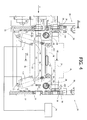
- Figure 4 is a front view according to the arrow IV of Figure 3;
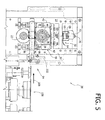
- Figure 5 is a side view according to the arrow V of Figure 4;
- Figure 6 is a partial cross section at an enlarged scale according to the arrow VI-VI of Figure 4; and
- Figure 7 is a cross section according to the line VII-VII of Figure 4.
- Designated by 20 in Figures 3 to 5 is a transverse-welding assembly for a flow-pack packaging machine, designed to form arrays of products of the "chaplet" type illustrated in Figures 1 and 2. The
welding assembly 20 comprises two counter-rotatingparallel shafts horizontal axes shafts bottom shaft 22 is able to rotate about afixed axis 26, and thetop shaft 24 is able to rotate about amobile axis 28. Of course, this arrangement could be reversed, i.e., with the axis of thetop shaft 24 fixed and the axis of thebottom shaft 22 mobile. Theshafts structure 30, which comprises twoparallel uprights 32 that extend in a vertical direction. - As may be seen in particular in Figure 4, the
bottom shaft 22 is supported by tworolling bearings 34, which define the fixed axis ofrotation 26. The outer rings of therolling bearings 34 are fixed with respect to thecorresponding uprights 32. - With reference to Figures 4, 5 and 6, the
top shaft 24 is supported in rotation about theaxis 28 by means of tworolling bearings 36. The outer rings of therolling bearings 36 are carried byrespective plates 38. - With reference in particular to Figures 5 and 6, each
plate 38 is carried by anadjustable frame 40. Eachplate 38 is mobile with respect to theframe 40 in a direction orthogonal with respect to the axis of rotation of theshaft 24. - With reference to Figures 5 and 6, the
adjustable frame 40 comprises twoside elements 42, atop cross member 44, and a bottom cross member. Theplate 38 carrying the bearing 36 engages in a slide-guide relationship theside elements 42 of theadjustable frame 40. Elastic compression means, constituted, for example, by twohelical compression springs 48, push theplate 38 downwards, so that it bears upon arrest surfaces 50 (Figure 6). Thecompression springs 48 are set between theplate 38 and thetop cross member 44 of theadjustable frame 40. Eachplate 38 is hence mobile with respect to theadjustable frame 40 against the action of thesprings 48 in a direction orthogonal with respect to the axis ofrotation 28 of thetop shaft 24. The simultaneous displacement of the twoplates 38 entails a displacement of the axis ofrotation 28 in a direction parallel to itself. - The two
adjustable frames 40 are both provided with a movement of adjustment in a vertical direction with respect to thefixed uprights 32. With reference to Figures 4, 5 and 6 eachmobile frame 40 is associated to anadjustment device 50, which controls a movement of adjustment of themobile frame 40 in a direction orthogonal to the axis ofrotation 28 of thetop shaft 24. With reference in particular to Figure 6, theadjustment device 50 comprises across member 52 fixed to the upright 32. Thecross member 52 has ahole 54, in which an adjustment bushing 56 is engaged in such a way that it is free to rotate. The adjustment bushing 56 has a threadedhole 58, engaged in which is ascrew 60 fixed to thetop cross member 44 of theadjustable frame 40. The adjustment bushing 56 has ahead 62 that rests against the bottom surface of the fixedcross member 52. Two Bellevillesprings 64 are set coaxially on the outside of the adjustment bushing 56 and keep thehead 62 of the adjustment bushing 56 in contact with the bottom surface of thecross member 52. The Belleville washers 64 act against aspacer 66, which is kept in a fixed position with respect to the adjustment bushing 56 by tworing nuts 68, which engage an external thread of the adjustment bushing 56. The adjustment bushing 56 has anactuation portion 70, which can be operated using a spanner for setting the adjustment bushing 56 in rotation about its own longitudinal axis. Theadjustment bushing 56 is associated to astationary indicator device 72, which is fixed with respect to thecross member 52 and has a graduated scale (not illustrated), which indicates the angular position of the adjustment bushing 56, which, in turn, corresponds uniquely to the position of theadjustable frame 40 with respect to theuprights 32. - The
device 50 enables adjustment of the position of themobile frame 40 with respect to the upright 32 and, consequently, enables variation of the distance between the axes ofrotation shafts - The two
shafts shafts shafts shafts - With reference to Figures 3 and 4, the two
shafts respective welding jaws shaft shaft welding jaws jaw respective welding portion - As illustrated in particular in Figure 7, the
welding portions welding portions electric resistance heaters 83. The temperature of the welding portions can be detected by means of a probe (not illustrated). Thewelding portions counterblade 86, which co-operate with one another for executing cutting of the material of the packaging in an area comprised between two adjacent weldedportions 14. The blade 84 and thecounterblade 86 are housed within respective seats of thewelding portions setscrews 88. The blade 84, or thecounterblade 86, or both of them, is/are adjustable in a direction orthogonal with respect to the axis of rotation of the corresponding shaft, for example by means of a screw with an end shaped like atruncated cone 90 that co-operates with aninclined surface 92 of the blade 84 or of thecounterblade 86. Alternatively, the adjustment could be performed by means of calibrated shims. - The
adjustment device 50 described previously enables adjustment of the mutual penetration between the undulated profiles of thewelding portions counterblade 86 with respect to thecorresponding welding portions counterblade 86 so as to obtain cutting of the packaging material. Said adjustments are performed during setting-up of the machine, and it may be necessary to carry out the adjustments again only as the characteristics of the sheet of packaging material used vary. - The adjustment of the interference between the blade 84 and the
counterblade 86 is set so as to obtain through cutting of the sheet of packaging material. - With reference to Figures 3, 4 and 5, the
welding assembly 20 according to the present invention is provided with anactuator device 94, operating under the control of theelectronic control unit 74, which enables displacement of the axis ofrotation 28 of thetop shaft 24 between a first operating position and a second operating position. The two operating positions are set in such a way that, in the first operating position, the blades andcounterblades 84, 86 of thejaws preferential failure 16, and, in the second operating position, the blades 84 and thecounterblades 86 effect complete cutting of the packaging material. In both of the operating positions, thewelding portions welding jaws welding portions - An embodiment of the
actuator device 94 is illustrated with reference to Figures 3 to 5. In this example of embodiment, theactuator device 94 comprises twoeccentric shafts 96, each of which is set in a position corresponding to a respective end of theshaft 24. Theshafts 96 extend orthogonal to theshaft 24 and are carried by respective supports fixed to theadjustable frames 40 carrying themobile shaft 28. In particular, the supports of the eccentric shafts are fixed to theside elements 42 of theframes 40. Theshafts 96 are mounted on the respective supports with an eccentricity substantially equal to the amplitude of the displacement of theaxis 28 between the first operating position and the second operating position. The twoeccentric shafts 96 co-operate with theshaft 24 by means of two pairs of rollingbearings eccentric shaft 96 and by thetop shaft 24. The rollingbearings - Each
eccentric shaft 96 is fixed to acontrol lever 102 that enables oscillation of theshaft 96 between two angular positions, corresponding, respectively, to the first operating position and the second operating position of thetop shaft 24. Movement of thelevers 102 is controlled by means oflinear actuators 104, each of which has a first end articulated to the fixedstructure 30 and a second end articulated to therespective lever 102. Theactuators 104, for example of a pneumatic type, are controlled by solenoid valves, controlled, in turn, by theelectronic control unit 74. - With reference to Figure 5, set upstream of the transverse-welding
assembly 20 is alongitudinal welding unit 106 of the type conventionally used in flow-pack packaging machines. The longitudinal welding unit carries out a continuous longitudinal weld of the sheet of packaging material, after prior bending according to a tubular configuration. - The packaging material bent into a tubular shape, welded in a longitudinal direction and containing the products to be packaged set at a distance from one another is fed to the transverse-welding
assembly 20 in the direction indicated by thearrows 108 in Figures 5 and 7. The transverse-weldingassembly 20 carries out thetransverse welds 14 in the space comprised between each pair of adjacent products. - The
top shaft 24 is normally kept in its first operating position, in which it is located at a greater distance from the fixedaxis 26. In this condition, the blades 84 andcounterblades 86 carry out anincision 16 without through cutting of the packaging material. After a pre-set number of incisions without cutting right through, theelectronic control unit 74 controls lowering of the axis ofrotation 28 via theactuators 104, in such a way that the blade andcounterblade 84, 86 perform a complete cutting of the packaging material. Immediately after performing complete cut, the welding assembly returns to the first position, in which it carries out the incision without complete cutting of the material. - This enables production of arrays of
products 10, as illustrated in Figure 1, formed by a pre-set number ofproducts 12 packaged individually and joined in series to one another by lines ofpreferential failure 16. - The number of products within each array can be varied via the
electronic control unit 74, without any need for intervention of adjustment on the transverse-weldingassembly 20. - The welding assembly according to the present invention can also be used to produce individual packages, with a complete cut for each weld. In this case, the operation would be identical to that of a normal flow-pack packaging machine.
Claims (8)
- A transverse-welding assembly (20) for flow-pack packaging machines, comprising two counter-rotating shafts (22, 24), which can turn about respective axes (26, 28) parallel to one another and each of which carries at least one welding jaw (76, 78), the welding jaws (76, 78) being provided with respective welding portions (80, 82) and, respectively, a cutting blade (84) and a counterblade (86), the jaws (76, 78) co-operating with one another for executing simultaneously welding and cutting of successive portions of packaging material,said transverse-welding assembly being characterized in that the axis of rotation (28) of one of said shafts (24) can be displaced with respect to the axis of rotation (26) of the other shaft (22) between a first operating position and a second operating position, in which in the first operating position the blade (84) and the counterblade (86) effect an incision (16) of the packaging material without complete cutting so as to form a line of preferential failure (16) and in which, in the second operating position, the blade (84) and the counterblade (86) effect complete cutting of the packaging material.
- The welding assembly according to Claim 1, characterized in that it comprises an actuator device (94) controlled by an electronic control unit (74), which controls displacement of the axis of rotation (28) from the first operating position to the second operating position, and vice versa, so as to carry out a complete cut after a pre-set number of incisions without complete cutting.
- The welding assembly according to Claim 2, characterized in that the shaft (24) with mobile axis of rotation (28) is carried by bearings (36) supported by mobile plates (38) pushed by elastic means (48) towards said second operating position.
- The welding assembly according to Claim 3, characterized in that said actuator assembly (94) comprises two eccentric shafts (96) co-operating with the shaft (24) with mobile axis (28) for pushing said shaft (24) towards said first operating position against the action of said elastic means (48).
- The welding assembly according to Claim 4, characterized in that said mobile plates (38) are carried by respective frames (40) with adjustable position.
- The welding assembly according to Claim 1, characterized in that said welding portions (80, 82) have respective active portions of undulated shape that penetrate one another in the welding configuration.
- The welding assembly according to Claim 1, characterized in that at least one between said blade (84) and counterblade (86) is adjustable with respect to the corresponding welding portion (80, 82).
- The welding assembly according to Claim 5, characterized in that each of said eccentric shafts (96) is carried by a respective frame (40) with adjustable position.
Priority Applications (1)
| Application Number | Priority Date | Filing Date | Title |
|---|---|---|---|
| EP06425695A EP1911567A1 (en) | 2006-10-09 | 2006-10-09 | Continuous transverse welding assembly for flow-pack packaging machines |
Applications Claiming Priority (1)
| Application Number | Priority Date | Filing Date | Title |
|---|---|---|---|
| EP06425695A EP1911567A1 (en) | 2006-10-09 | 2006-10-09 | Continuous transverse welding assembly for flow-pack packaging machines |
Publications (1)
| Publication Number | Publication Date |
|---|---|
| EP1911567A1 true EP1911567A1 (en) | 2008-04-16 |
Family
ID=37735010
Family Applications (1)
| Application Number | Title | Priority Date | Filing Date |
|---|---|---|---|
| EP06425695A Withdrawn EP1911567A1 (en) | 2006-10-09 | 2006-10-09 | Continuous transverse welding assembly for flow-pack packaging machines |
Country Status (1)
| Country | Link |
|---|---|
| EP (1) | EP1911567A1 (en) |
Cited By (4)
| Publication number | Priority date | Publication date | Assignee | Title |
|---|---|---|---|---|
| WO2012173558A1 (en) * | 2011-06-15 | 2012-12-20 | Tetra Laval Holdings & Finance S.A. | Suspension for a sealing jaw and method for calibrating sealing jaws |
| US10800564B2 (en) | 2013-11-05 | 2020-10-13 | Oakbridge Investments Limited | Apparatus and method for cutting and/or crimping wrapping material |
| EP3621885A4 (en) * | 2017-05-12 | 2020-11-25 | Delta Systems & Automation LLC | HEAD FOR HORIZONTAL TUBE BAG PACKAGING MACHINE |
| CN113000709A (en) * | 2021-03-08 | 2021-06-22 | 浙江东盛精密机械有限公司 | Lead weight cutting and forming device |
Citations (4)
| Publication number | Priority date | Publication date | Assignee | Title |
|---|---|---|---|---|
| GB1243465A (en) * | 1968-01-22 | 1971-08-18 | Doughboy Ind Inc | Improvements in and relating to packaging machines |
| EP0718195A1 (en) * | 1994-12-23 | 1996-06-26 | ISHIDA CO., Ltd. | Transverse sealer |
| JPH10329813A (en) * | 1997-05-30 | 1998-12-15 | Tokiwa Kogyo Kk | Sealing device |
| DE102004008984A1 (en) * | 2004-02-23 | 2005-09-01 | Robert Bosch Gmbh | Sealing roller system for packaging machine has the roller axes fitted to side supports linked by flexible bending strips bent by threaded adjusters to vary the roller spacing |
-
2006
- 2006-10-09 EP EP06425695A patent/EP1911567A1/en not_active Withdrawn
Patent Citations (4)
| Publication number | Priority date | Publication date | Assignee | Title |
|---|---|---|---|---|
| GB1243465A (en) * | 1968-01-22 | 1971-08-18 | Doughboy Ind Inc | Improvements in and relating to packaging machines |
| EP0718195A1 (en) * | 1994-12-23 | 1996-06-26 | ISHIDA CO., Ltd. | Transverse sealer |
| JPH10329813A (en) * | 1997-05-30 | 1998-12-15 | Tokiwa Kogyo Kk | Sealing device |
| DE102004008984A1 (en) * | 2004-02-23 | 2005-09-01 | Robert Bosch Gmbh | Sealing roller system for packaging machine has the roller axes fitted to side supports linked by flexible bending strips bent by threaded adjusters to vary the roller spacing |
Cited By (6)
| Publication number | Priority date | Publication date | Assignee | Title |
|---|---|---|---|---|
| WO2012173558A1 (en) * | 2011-06-15 | 2012-12-20 | Tetra Laval Holdings & Finance S.A. | Suspension for a sealing jaw and method for calibrating sealing jaws |
| US9656774B2 (en) | 2011-06-15 | 2017-05-23 | Tetra Laval Holdings & Finance S.A. | Suspension for a sealing jaw and method for calibrating sealing jaws |
| US10800564B2 (en) | 2013-11-05 | 2020-10-13 | Oakbridge Investments Limited | Apparatus and method for cutting and/or crimping wrapping material |
| EP3621885A4 (en) * | 2017-05-12 | 2020-11-25 | Delta Systems & Automation LLC | HEAD FOR HORIZONTAL TUBE BAG PACKAGING MACHINE |
| US11273934B2 (en) | 2017-05-12 | 2022-03-15 | Delta Systems And Automation Llc | Head for horizontal flow wrapper packaging machine |
| CN113000709A (en) * | 2021-03-08 | 2021-06-22 | 浙江东盛精密机械有限公司 | Lead weight cutting and forming device |
Similar Documents
| Publication | Publication Date | Title |
|---|---|---|
| EP3715267B1 (en) | Work station for a packing machine | |
| CN102378675B (en) | Device for processing a packing material using ultrasound | |
| US5771660A (en) | Transverse sealing apparatus for a tubular bag packaging machine | |
| WO2012152528A1 (en) | Method for operating a transverse-seam-sealing arrangement in a tubular-bag machine, and transverse-seam-sealing arrangement in a tubular-bag machine | |
| US5511363A (en) | Vertical cyclically operating flat sack machine | |
| EP3621885B1 (en) | Heads for horizontal flow wrapper packaging machine and method | |
| EP3717189B1 (en) | Device and method for selectively shear a support element, preferably a continuous strip | |
| US20150321270A1 (en) | Co-moving hydraulic shears without stand | |
| JP5393753B2 (en) | Cutter unit | |
| JP5610385B2 (en) | End seal device and automatic packaging machine equipped with the end seal device | |
| EP1782930B1 (en) | Device for trimming printed products | |
| US3961512A (en) | Metal punching machine | |
| CN112918804B (en) | A double-row three-side-sealed vertical packaging machine | |
| EP4192746B1 (en) | Horizontal packaging machine with adjustable cut-sew group | |
| WO2010115662A1 (en) | Device for processing a packing material using ultrasound | |
| DE102019114126A1 (en) | Workstation for a packaging machine | |
| US5467580A (en) | Automatic packaging machine | |
| CN107087658B (en) | Method and device for cutting dough fed from an extruder | |
| JP7316658B2 (en) | Vertical form-fill-seal packaging machine and shaft replacement method | |
| US5622026A (en) | Welding and cutting device for film-wrapped packaging | |
| JP2014156250A (en) | Three-way seal multi-row automatic packing machine | |
| US757604A (en) | Apparatus for cutting metal bars. | |
| KR200241867Y1 (en) | Box packing paper moving device for printing | |
| US1193020A (en) | Sheet-metal shear | |
| EP4446074A1 (en) | Device for cutting or punching dough |
Legal Events
| Date | Code | Title | Description |
|---|---|---|---|
| PUAI | Public reference made under article 153(3) epc to a published international application that has entered the european phase |
Free format text: ORIGINAL CODE: 0009012 |
|
| AK | Designated contracting states |
Kind code of ref document: A1 Designated state(s): AT BE BG CH CY CZ DE DK EE ES FI FR GB GR HU IE IS IT LI LT LU LV MC NL PL PT RO SE SI SK TR |
|
| AX | Request for extension of the european patent |
Extension state: AL BA HR MK RS |
|
| AKX | Designation fees paid | ||
| REG | Reference to a national code |
Ref country code: DE Ref legal event code: 8566 |
|
| STAA | Information on the status of an ep patent application or granted ep patent |
Free format text: STATUS: THE APPLICATION IS DEEMED TO BE WITHDRAWN |
|
| 18D | Application deemed to be withdrawn |
Effective date: 20081017 |