EP1911544A2 - Method for feeding an output shaft of a power tool - Google Patents
Method for feeding an output shaft of a power tool Download PDFInfo
- Publication number
- EP1911544A2 EP1911544A2 EP08002591A EP08002591A EP1911544A2 EP 1911544 A2 EP1911544 A2 EP 1911544A2 EP 08002591 A EP08002591 A EP 08002591A EP 08002591 A EP08002591 A EP 08002591A EP 1911544 A2 EP1911544 A2 EP 1911544A2
- Authority
- EP
- European Patent Office
- Prior art keywords
- tubular member
- output shaft
- workpiece
- fluid chamber
- tubular
- Prior art date
- Legal status (The legal status is an assumption and is not a legal conclusion. Google has not performed a legal analysis and makes no representation as to the accuracy of the status listed.)
- Withdrawn
Links
Images


Classifications
-
- B—PERFORMING OPERATIONS; TRANSPORTING
- B23—MACHINE TOOLS; METAL-WORKING NOT OTHERWISE PROVIDED FOR
- B23Q—DETAILS, COMPONENTS, OR ACCESSORIES FOR MACHINE TOOLS, e.g. ARRANGEMENTS FOR COPYING OR CONTROLLING; MACHINE TOOLS IN GENERAL CHARACTERISED BY THE CONSTRUCTION OF PARTICULAR DETAILS OR COMPONENTS; COMBINATIONS OR ASSOCIATIONS OF METAL-WORKING MACHINES, NOT DIRECTED TO A PARTICULAR RESULT
- B23Q5/00—Driving or feeding mechanisms; Control arrangements therefor
- B23Q5/22—Feeding members carrying tools or work
- B23Q5/26—Fluid-pressure drives
- B23Q5/261—Fluid-pressure drives for spindles
-
- Y—GENERAL TAGGING OF NEW TECHNOLOGICAL DEVELOPMENTS; GENERAL TAGGING OF CROSS-SECTIONAL TECHNOLOGIES SPANNING OVER SEVERAL SECTIONS OF THE IPC; TECHNICAL SUBJECTS COVERED BY FORMER USPC CROSS-REFERENCE ART COLLECTIONS [XRACs] AND DIGESTS
- Y10—TECHNICAL SUBJECTS COVERED BY FORMER USPC
- Y10T—TECHNICAL SUBJECTS COVERED BY FORMER US CLASSIFICATION
- Y10T408/00—Cutting by use of rotating axially moving tool
- Y10T408/55—Cutting by use of rotating axially moving tool with work-engaging structure other than Tool or tool-support
- Y10T408/561—Having tool-opposing, work-engaging surface
- Y10T408/5623—Having tool-opposing, work-engaging surface with presser foot
- Y10T408/56245—Having tool-opposing, work-engaging surface with presser foot including tool-guide [or bushing]
-
- Y—GENERAL TAGGING OF NEW TECHNOLOGICAL DEVELOPMENTS; GENERAL TAGGING OF CROSS-SECTIONAL TECHNOLOGIES SPANNING OVER SEVERAL SECTIONS OF THE IPC; TECHNICAL SUBJECTS COVERED BY FORMER USPC CROSS-REFERENCE ART COLLECTIONS [XRACs] AND DIGESTS
- Y10—TECHNICAL SUBJECTS COVERED BY FORMER USPC
- Y10T—TECHNICAL SUBJECTS COVERED BY FORMER US CLASSIFICATION
- Y10T408/00—Cutting by use of rotating axially moving tool
- Y10T408/65—Means to drive tool
- Y10T408/675—Means to drive tool including means to move Tool along tool-axis
- Y10T408/6757—Fluid means
Definitions
- the first tubular member further includes a biasing member such as a coil spring for assisting in retracting the output shaft.
- the biasing member is disposed within a biasing member retaining tube disposed fixedly relative to the first tubular sleeve and concentrically therewith such that it is able to receive the output shaft therethrough.
- Figure 1 is a perspective view of a power feed apparatus in accordance with a preferred embodiment of the present invention also showing a supporting structure for supporting the apparatus relative to a workpiece;
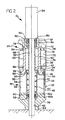
- Figure 2 is a simplified cross sectional side view of the apparatus of Figure 1 taken in accordance with section line 2-2 in Figure 1 showing the apparatus with an output shaft in a retracted position, and omitting the mounting structure shown in Figure 1 ;
- Figure 3 is a view of the apparatus of Figure 2 showing the output shaft in an extended position.
- FIG. 1 there is shown a power feed apparatus 10 in accordance with a preferred embodiment of the present invention.
- the apparatus 10 is illustrated as being supported by a guide shaft assembly 12 which is secured to the apparatus 10.
- the apparatus 10 is secured against a workpiece 14 by a clamp 16.
- the apparatus 10 can be secured to the workpiece 14 in a number of different ways, some of which do not include the requirement of a clamp 16.
- the apparatus 10 generally includes a first tubular member 18 and a second tubular member 20 disposed concentrically with the first tubular member 18.
- the first tubular member 18 includes a port 22 which is coupled to a fluid line 24.
- the fluid line 24 is in communication with a pressurized fluid source 26 to thus allow pressurized fluid to be supplied into an interior area of the first tubular member 18.
- the second tubular member 20 includes a fluid port 28 which is in communication with a fluid line 30 which is also in communication with the pressurized fluid source 26.
- a suitable valve 32 can be used to direct fluid from the pressurized fluid source 26 into either the fluid port 22 or the fluid port 28. Alternatively, separate pressurized fluid sources could be employed for the two fluid ports 22 and 28.
- the second tubular member 20 is adapted to fixedly support a tool 34.
- the tool comprises a drill having an electric motor. It will be appreciated, however, that other forms of tools, either electrically, hydraulically or pneumatically driven, having an output shaft could conceivably be carried by the apparatus 10.
- a biasing element such as a coil spring 42.
- the fluid port 22 Is formed by a flow path 44 created between a first wall portion 46 and a second wall portion 48 of the tubular sleeve 36. This flow path 44 leads into a first annular fluid chamber 50. It is important to note that the first annular fluid chamber 50 is disposed concentrically with a rotationally driven output shaft 52 of the motor 34.
- the biasing member 42 and the biasing member retaining tube 40 are also disposed concentrically with the output shaft 42.
- An annular pocket 54 is formed between the biasing member retaining tube 40 and an inner wall 56 of the tubular sleeve 36.
- the motor 34 and its output shaft 52 in this example form an electrically driven drill.
- guide element 80 includes a main body portion 90 having a lower end with a flange 92.
- the main body portion 90 extends through an opening 93 in a guide element 94 and into contact with the biasing member 42.
- the flange 92 has diameter which allows it to be inserted within the biasing member retaining tube 40 and to move slidably up and down within tube 40 as the output shaft 52 is moved between extended and retracted positions.
- fluid port 28 needs to be free to expel fluid collected in the annular fluid chamber 72 through the fluid passageway 70.
- a flow control device could be employed at fluid port 28 to control the downward thrust and/or speed of the output shaft 52.
- a power feed apparatus for feeding a working element attached to an output shaft of a power tool in a linear motion relative to a workpiece so as to distribute a thrust force applied to said output shaft evenly concentrically about said output shaft
- said apparatus comprising; a first tubular member adapted to be coupled to a substructure associated with said workpiece, said first tubular member having a first fluid port; a second tubular member adapted to move slidably relative to said first tubular member, said second tubular member being adapted to support said output shaft of said motor concentrically relative to said first tubular member; surfaces of said tubular members defining a first fluid chamber therebetween arranged concentrically about said output shaft; and wherein fluid pressure from a fluid source directed into said fluid chamber operates to urge said second tubular member, and thus said output shaft, linearly relative to said first tubular member into an extended position and to distribute a thrust force evenly concentrically about said output shaft.
- a power feed apparatus for feeding an output shaft of a power tool in a linear motion relative to a workpiece without impeding rotational movement of said output shaft, and in a manner which distributes thrust forces imparted to said output shaft evenly concentrically about said output shaft while said output shaft is moved linearly between a retracted position and an extended position
- said apparatus comprising: a first tubular member including an outer sleeve and an inner tube defining an annular area therebetween, said first tubular member adapted to be fixedly secured to a substructure associated with said workpiece; a second tubular member including a second outer tubular sleeve and a second inner tubular sleeve disposed concentrically within said second outer sleeve, said output shaft being supported from said second tubular member and extending concentrically through said second inner tubular sleeve and said inner tube; said outer sleeve and said inner tube defining a first annular area therebetween in which a portion of said second inner tubular sleeve travel
- said second outer tubular sleeve and said second inner tubular sleeve form a second annular fluid chamber therebetween such that said pressurized fluid injected into said second annular fluid chamber, while said first annular fluid chamber is not pressurized with said pressurized fluid, causes movement of said second tubular member, and thus said output shaft, from said extended position to said retracted position.
- said first tubular member includes a mounting component for enabling said apparatus to be fixedly secured to said substructure associated with said workpiece.
- the apparatus further comprising at least one O-ring seal disposed between said outer sleeve and said inner tube.
Landscapes
- Engineering & Computer Science (AREA)
- Mechanical Engineering (AREA)
- Machine Tool Units (AREA)
- Drilling And Boring (AREA)
- Milling, Broaching, Filing, Reaming, And Others (AREA)
- Transmission Devices (AREA)
Abstract
Description
- This invention relates to pneumatic/hydraulic power tools, and more particularly to a pressurized fluid driven power feed apparatus for concentrically applying thrust forces to an output shaft of a tool in a manner which distributes the thrust forces evenly concentrically about the output shaft.
- In aircraft assembly operations, it is often necessity to clamp or otherwise attach a hand operated drill style reamer onto a spar or other area of a workplace so that the reamer can be automatically operated. This has involved incorporating a pneumatic/hydraulic cylinder attached to some form of carriage, which is in turn coupled to the power tool that is performing the machining operation, whether it be drilling, cutting or reaming. As such, the pneumatic/hydraulic cylinder is laterally offset from the power tool.
- The problem that arises is one of keeping the rotating working element attached to the output shaft of the tool perpendicular to the pneumatic cylinder. Put differently, the output shaft has to be maintained parallel to the cylinder and normal to the surface of the workpiece. Typically, guide rails or some other form of guide structure are attached to the tool in an attempt to keep the output shaft of the tool perfectly parallel to the cylinder and normal to the workpiece surface. These normality problems become less of a problem in larger tools as larger carriage bearings or guide rails are normally used. However, with smaller tools, the moment that is produced due to the high thrust loads and the distance between the component secured to the output shaft of the tool, such as a cutter, and the cylinder providing the thrust force causes the cutter to twist, thus pushing the cutter out of its alignment parallel to the surface of the workpiece. In a reaming operation, this can cause the cutter to exceed a predetermined hole tolerance for holes being formed in the workpiece.
- The guide rail system presently used to align and support power tools also requires exacting tolerances which are quite difficult to maintain. Up until the present time, this problem of maintaining the correct angularity of the tool relative to the pneumatic/hydraulic cylinder has required the use of larger bushings and/or guides, which causes the overall assembly to become much more cumbersome to handle and set up and to require much more space.
- It would therefore be highly desirable to provide some form of apparatus which can be used to support a tool and to provide thrust forces evenly (i.e., concentrically) about the output shaft of the tool as the output shaft is guided toward a workpiece. This would eliminate the need for large, heavy and cumbersome guide rail systems and/or carriages and would ensure that the thrust forces acting on the output shaft are applied evenly about the output shaft, and thus also evenly about the working element attached to the output shaft. Such an apparatus would also provide a more compact means for supporting the tool and its working element.
- The present invention is directed to a power feed apparatus for feeding a working element attached to an output shaft of a motor driven power tool in a linear motion relative to a workpiece. The present invention enables a thrust force to be applied evenly about a periphery of the output shaft, and thus evenly about the working element, to ensure that the working element remains parallel to a surface of the workpiece as the thrust force is applied.
- In one preferred form, the apparatus comprises a first tubular member which is adapted to be fixed to a substructure associated with a workpiece such as a jig, carriage or other like structure. A second tubular member is provided and moves slidably relative to the first tubular member. The second tubular member supports the tool thereon and allows the output shaft of the tool to extend therethrough into the first tubular member. The first tubular member includes a first annular fluid chamber arranged concentrically around the output shaft. The second tubular member similarly includes a second annular fluid chamber formed concentrically with the output shaft. The first tubular member further includes a bore at one end for enabling the output shaft of the tool to extend therethrough and toward and/or into a workpiece.
- In operation, when a pressurized fluid is injected into the first annular fluid chamber, this causes the second tubular member to move slidably linearly relative to the first tubular member. This causes the output shaft of the tool to be moved linearly from a retracted position into an extended position wherein the working element attached to the output shaft can be used to perform a machining operation, such as reaming, for example, on the workpiece. When the working element is to be retracted, a pressurized fluid is removed from the first annular fluid chamber and injected into the second annular fluid chamber. This causes the second tubular member to be moved slidably in an opposite direction such that the output shaft is retracted, thus withdrawing the working element from the workpiece.
- In a preferred embodiment the first tubular member further includes a biasing member such as a coil spring for assisting in retracting the output shaft. The biasing member is disposed within a biasing member retaining tube disposed fixedly relative to the first tubular sleeve and concentrically therewith such that it is able to receive the output shaft therethrough.
- The power feed apparatus of the present invention thus allows a pneumatic or hydraulic thrust force to be applied evenly and concentrically about an output shaft of the power tool. This allows the output shaft to be driven in a smooth, linear motion without creating any external forces which would tend to act on the working element to force it out of its perfectly parallel alignment with a work surface. Advantageously, the power feed apparatus of the present invention also forms a very compact assembly which can be secured readily to a jig or other supporting structure associated with the workpiece.
- Further areas of applicability of the present invention will become apparent from the detailed description provided hereinafter. It should be understood that the detailed description and specific examples, while indicating the preferred embodiment of the invention, are intended for purposes of illustration only and are not intended to limited the scope of the invention.
- The present invention will become more fully understood from the detailed description and the accompanying drawings, wherein:
-
Figure 1 is a perspective view of a power feed apparatus in accordance with a preferred embodiment of the present invention also showing a supporting structure for supporting the apparatus relative to a workpiece; -
Figure 2 is a simplified cross sectional side view of the apparatus ofFigure 1 taken in accordance with section line 2-2 inFigure 1 showing the apparatus with an output shaft in a retracted position, and omitting the mounting structure shown inFigure 1 ; and -
Figure 3 is a view of the apparatus ofFigure 2 showing the output shaft in an extended position. - The following description of the preferred embodiment(s) is merely exemplary in nature and is in no way intended to limit the invention, its application, or uses.
- Referring to
Figure 1 , there is shown a power feed apparatus 10 in accordance with a preferred embodiment of the present invention. The apparatus 10 is illustrated as being supported by a guide shaft assembly 12 which is secured to the apparatus 10. The apparatus 10 is secured against aworkpiece 14 by aclamp 16. As will be described in greater detail, the apparatus 10 can be secured to theworkpiece 14 in a number of different ways, some of which do not include the requirement of aclamp 16. - The apparatus 10 generally includes a first
tubular member 18 and a secondtubular member 20 disposed concentrically with the firsttubular member 18. The firsttubular member 18 includes aport 22 which is coupled to afluid line 24. Thefluid line 24 is in communication with a pressurizedfluid source 26 to thus allow pressurized fluid to be supplied into an interior area of the firsttubular member 18. The secondtubular member 20 includes afluid port 28 which is in communication with afluid line 30 which is also in communication with the pressurizedfluid source 26. Asuitable valve 32 can be used to direct fluid from the pressurizedfluid source 26 into either thefluid port 22 or thefluid port 28. Alternatively, separate pressurized fluid sources could be employed for the twofluid ports - The second
tubular member 20 is adapted to fixedly support atool 34. In one preferred form the tool comprises a drill having an electric motor. It will be appreciated, however, that other forms of tools, either electrically, hydraulically or pneumatically driven, having an output shaft could conceivably be carried by the apparatus 10. - In general operation, when pressurized fluid is applied via
fluid line 24 intofluid port 22, this causes the secondtubular member 20 to move linearly downwardly over firsttubular member 18. Consequently, the output shaft of themotor 34 is urged linearly downwardly in the drawing ofFigure 1 into theworkpiece 14. Typically the output shaft has coupled at an end a working element such as a reamer. Again, it will be appreciated that a wide variety of metal working devices could be employed in connection with the apparatus 10 and that the following description should not be limited to only a reamer. - A principal advantage of the apparatus 10 is that the thrust forces produced by the pressurized fluid are applied evenly and concentrically about the output shaft such that the output shaft is maintained perfectly perpendicular to the upper surface of the
workpiece 14. This is in contrast to previously developed systems which employ a cylinder positioned off to one side of the tool, and which impart forces during the thrust motion that tend to urge the output shaft of the motor out of its perpendicular alignment to the surface of theworkpiece 14. - Although the guide shaft assembly 12 is not considered to be a part of the apparatus 10, a brief description of its function will also be provided. The guide shaft assembly 12 includes a
guide bracket 12a which is attached directly to themotor 34. Theguide bracket 12a is in turn attached to ananti-rotation shaft 12b, which is in turn attached to aguide bracket 12c.Guide bracket 12c is fixedly secured to an outer surface 36a of the firsttubular member 18. Thecomponents motor 34 relative to the firsttubular member 18 as themotor 34 operates, while still allowing the secondtubular member 20 to move down linearly over the firsttubular member 18. A nosepiece 18a, integrally formed with the firsttubular member 18, provides one means for allowing the firsttubular member 18 to be fixedly secured via theclamp 16 to thework piece 14. Alternatively, the nosepiece 18a could be secured to a jig or other device associated with thework piece 14. Thus, it will be appreciated that various other schemes may be employed to support the apparatus 10 fixedly relative to a work piece. - Referring now to
Figures 2 and3 , the internal components of the apparatus 10 will be described in greater detail. The firsttubular member 18 includes a first or outertubular sleeve 36 having the outer surface 36a mentioned in connection with the discussion ofFigure 1 , a mountingcomponent 38 and a biasingmember retaining tube 40. It will be appreciated that for simplicity, the mountingcomponent 38 is shown without the nosepiece 18a formed therewith. - Within the biasing
member retaining tube 40 is disposed a biasing element, such as acoil spring 42. Thefluid port 22 Is formed by aflow path 44 created between afirst wall portion 46 and asecond wall portion 48 of thetubular sleeve 36. Thisflow path 44 leads into a firstannular fluid chamber 50. It is important to note that the firstannular fluid chamber 50 is disposed concentrically with a rotationally drivenoutput shaft 52 of themotor 34. The biasingmember 42 and the biasingmember retaining tube 40 are also disposed concentrically with theoutput shaft 42. Anannular pocket 54 is formed between the biasingmember retaining tube 40 and aninner wall 56 of thetubular sleeve 36. Themotor 34 and itsoutput shaft 52 in this example form an electrically driven drill. - The
tubular sleeve 18 is threadably secured to the mountingcomponent 38. Similarly, the biasingmember retaining tube 40 includes a lower threadedend 58 which is secured within a threadedbore 60 of the mountingcomponent 38. The mountingcomponent 38 includes acentral bore 62 for allowing theoutput shaft 52 to extend therethrough toward theworkpiece 14. (not shown inFigure 2 ). Alower bearing pack 60a and an associatedseal 60b are also disposed within the threaded bore 60 internal to the biasingmember retaining tube 40. Optionally, the mountingcomponent 38 may include a lower threadedend 64 which may be threadably engaged with a threaded bore in a jig or other like structure to support the apparatus 10 fixedly relative to the jig or like structure. - With continuing reference to
Figure 2 , the secondtubular member 20 includes an outertubular sleeve 66 and an innertubular sleeve 68. The outertubular sleeve 66 includes afluid flow passageway 70 in communication with thefluid port 28.Fluid passageway 70 communicates with anannular fluid chamber 72 which is arranged concentrically with theoutput shaft 52. Theannular fluid chamber 72 is formed between anouter surface 74 of the innertubular sleeve 68 and aninner surface 76 of the outertubular sleeve 66. Anupper end portion 78 of the innertubular sleeve 68 is threadably engaged with anupper mounting component 80, which is in turn threadably engaged with a threaded portion (not shown) of a housing of themotor 34. The outertubular sleeve 66 is threaded onto theupper mounting component 80 at the threaded bore 82. In this particular embodiment, the secondtubular member 20 provides a micrometer depth stop and a hard stop for the firsttubular member 18 as it slides into the secondtubular member 20. The micrometer depth is held systematically by alocknut 97. Within theupper mounting component 80 is disposed an upper bearing pack 81a and an associated seal 81 b. Bearing packs 81 a and 60a help to maintain theoutput shaft 52 concentric within the first and secondtubular members - Referring further to
Figure 2 , a first O-ring seal 84 provides a seal between the outer surface of the innertubular sleeve 68 at its upper end and an inner surface of the outertubular sleeve 66. A second O-ring seal 86 provides a seal between the outer surface of the innertubular sleeve 68 and an inner surface of the outertubular sleeve 36. A third O-ring seal 88 disposed between a lowerouter edge 89 of the innertubular sleeve 68 and theinner wall 56 of the outertubular sleeve 36 provides a seal at this area. O-ring seals annular fluid chamber 72 when a pressurized fluid is injected therein. O-ring seals annular flow chamber 50 when a pressurized fluid is injected thereinto. - With further reference to
Figure 2 ,guide element 80 includes amain body portion 90 having a lower end with aflange 92. Themain body portion 90 extends through anopening 93 in aguide element 94 and into contact with the biasingmember 42. Theflange 92 has diameter which allows it to be inserted within the biasingmember retaining tube 40 and to move slidably up and down withintube 40 as theoutput shaft 52 is moved between extended and retracted positions. - Turning now to the operation of the apparatus 10, when a pressurized fluid is applied to
port 22, this causes theannular fluid chamber 50 to be filled with the pressurized fluid. This causes the innertubular sleeve 68 of the secondtubular member 20 to be driven downwardly in the drawing ofFigure 2 into the position shown inFigure 3 . Importantly, the thrust force that the pressurized fluid provides is distributed evenly and concentrically about theoutput shaft 52. Thus, there are no external forces applied to theoutput shaft 52 which tend to urge it off center of an axis extending perfectly perpendicular to an upper surface of theworkpiece 14. The force of the pressurized fluid compresses the biasingelement 42 as theguide member 80 is driven downwardly together with the innertubular sleeve 68. It will be appreciated that during this movement of theoutput shaft 52 into an extended position, that thefluid port 28 needs to be free to expel fluid collected in theannular fluid chamber 72 through thefluid passageway 70. Also, optionally, a flow control device could be employed atfluid port 28 to control the downward thrust and/or speed of theoutput shaft 52. - As the second
tubular member 20 moves downwardly in the drawing ofFigure 2 , the outertubular sleeve 66 and thetubular sleeve 68 are guided by the outertubular sleeve 36 of the firsttubular member 18. This helps to ensure that theguide member 80 remains perfectly concentric with the longitudinal axis of theoutput shaft 52. The apparatus 10 is shown with theoutput shaft 52 in its fully extended position inFigure 3 . - When the
output shaft 52 is to be retracted (i.e., moved back into the position shown inFigure 2 ), the fluid pressure applied toport 22 is removed, thereby allowing fluid collected within theannular fluid chamber 50 to be expelled out through theflow path 44 and theport 22. This occurs simultaneously as a pressurized fluid is directed intoport 28, throughflow paths 70 and into theannular flow chamber 72. The fluid enteringannular flow chamber 72 acts on the second outertubular sleeve 66 to urge thesleeve 66 upwardly in the drawing ofFigure 2 . The biasingmember 42 also assists in urging the entire secondtubular member 20 upwardly away from the firsttubular member 18. Upward retracting movement of the secondtubular member 20 is limited by engagement of atop surface 98 of firsttubular member 18 that abuts a flange 99 of the outertubular sleeve 66. It will be appreciated that in some applications the biasingmember 42 by itself may be sufficient to provide the needed retracting force. - The apparatus 10 of the present invention thus provides a simple, very compact means for applying thrust forces to an output shaft of a tool in a manner which does not tend to force the output shaft out of perfect perpendicular alignment with the outer surface of a workpiece. Since the apparatus 10 does not require any external carriage or guide rail system, it forms a much more compact system which can be handled, set up and used much more easily and conveniently on various types of workpieces, In particular, the invention is ideally suited to aircraft manufacturing operations where high precision drilling and reaming operations are employed to form very precise diameter holes in various size and shaped components.
- Those skilled in the art can now appreciate from the foregoing description that the broad teachings of the present invention can be implemented in a variety of forms. Therefore, while this invention has been described in connection with particular examples thereof, the true scope of the invention should not be so limited since other modifications will become apparent to the skilled practitioner upon a study of the drawings, specification and following claims.
A power feed apparatus for feeding a working element attached to an output shaft of a power tool in a linear motion relative to a workpiece so as to distribute a thrust force applied to said output shaft evenly concentrically about said output shaft, said apparatus comprising; a first tubular member adapted to be coupled to a substructure associated with said workpiece, said first tubular member having a first fluid port; a second tubular member adapted to move slidably relative to said first tubular member, said second tubular member being adapted to support said output shaft of said motor concentrically relative to said first tubular member; surfaces of said tubular members defining a first fluid chamber therebetween arranged concentrically about said output shaft; and wherein fluid pressure from a fluid source directed into said fluid chamber operates to urge said second tubular member, and thus said output shaft, linearly relative to said first tubular member into an extended position and to distribute a thrust force evenly concentrically about said output shaft.
Preferably said tubular members define a second fluid chamber independent of said first fluid chamber; and wherein a pressurized fluid admitted into said second fluid chamber causes linear movement of said second tubular member, and thus said output shaft, from said extended position to a retracted position.
Preferably said first tubular member comprises a biasing element for applying a force to said second tubular member to urge said second tubular member from said extended position into a retracted position when said fluid pressure is removed from said first fluid port.
Preferably said second tubular member comprises an outer tubular sleeve and an inner tubular sleeve disposed concentrically within said outer tubular sleeve, for guiding said second tubular member slidably relative to said first tubular member.
Preferably said first tubular member comprises an outer sleeve and an inner sleeve disposed concentrically within said outer sleeve to define an annular area therebetween for guiding-apportion of said second tubular member.
Preferably said first tubular member comprises a mounting component adapted for coupling to said substructure, said mounting component having a bore for permitting linear movement of said output shaft therethrough.
A power feed apparatus for feeding an output shaft of a power tool in a linear motion relative to a workpiece without impeding rotational movement of said output shaft, and in a manner which distributes thrust forces imparted to said output shaft evenly concentrically about said output shaft while said output shaft is moved linearly between a retracted position and an extended position said apparatus comprising: a first tubular member including an outer sleeve and an inner tube defining an annular area therebetween, said first tubular member adapted to be fixedly secured to a substructure associated with said workpiece; a second tubular member including a second outer tubular sleeve and a second inner tubular sleeve disposed concentrically within said second outer sleeve, said output shaft being supported from said second tubular member and extending concentrically through said second inner tubular sleeve and said inner tube; said outer sleeve and said inner tube defining a first annular area therebetween in which a portion of said second inner tubular sleeve travels during movement of said second tubular member; and a first annular fluid chamber formed between said second inner tubular sleeve and said outer sleeve such that a pressurized fluid admitted into said first fluid chamber causes linear movement of said output shaft from said retracted position to said extended position.
Preferably said second outer tubular sleeve and said second inner tubular sleeve form a second annular fluid chamber therebetween such that said pressurized fluid injected into said second annular fluid chamber, while said first annular fluid chamber is not pressurized with said pressurized fluid, causes movement of said second tubular member, and thus said output shaft, from said extended position to said retracted position.
Preferably said first tubular member includes a mounting component for enabling said apparatus to be fixedly secured to said substructure associated with said workpiece.
The apparatus further comprising at least one O-ring seal disposed between said outer sleeve and said inner tube.
Preferably said inner tube comprises a biasing member retaining tube disposed fixedly concentrically with said outer sleeve; and said second tubular member includes an output shaft guide tube disposed concentrically within said second outer tubular sleeve; wherein said apparatus further includes a biasing member disposed within said biasing member retaining tube; and wherein said biasing member acts on said output shaft guide tube to assist in retracting said output shaft when said fluid pressure is removed from said second annular fluid chamber.
The apparatus further comprising a bearing assembly disposed in said mounting component for helping to maintain said output shaft concentrically within said first tubular member.
The apparatus further comprising a bearing assembly mounted in said second tubular member for helping to maintain said output shaft concentrically within said second tubular member.
Claims (2)
- A method for feeding an output shaft of a power tool in a linear motion relative to a workpiece without impeding rotational movement of said output shaft, and in a manner which distributes thrust forces imparted to said output shaft evenly concentrically about said output shaft while said output shaft is moved linearly between a retracted position and an extended position, relative to a workpiece, the method comprising:providing a first tubular member which is adapted to be fixedly attached to a substructure associated with said workpiece, and which includes a bore for permitting said output shaft to extend therethrough into said workpiece; providing a second tubular member having a diameter sufficiently large to permit sliding movement over said first tubular member, said second tubular member including a portion arranged to extend within an interior area of said first tubular member, said second tubular member supporting a motor thereon for driving said output shaft, and said working element being aligned concentrically with said bore in said first tubular member;forming a first annular fluid chamber within said first tubular member for causing said second tubular member to be urged linearly toward said first tubular member when a pressurized fluid is injected into said first annular fluid chamber, thereby causing said output shaft to be extended from said first tubular member toward said workpiece; andforming a second annular fluid chamber within said second tubular member for causing said second tubular member to be retracted away from said workpiece when a pressurized fluid is injected into said second annular fluid chamber.
- The method of claim 14, further comprising using a spring disposed within one of said first or second tubular members to assist in retracting said output shaft.
Applications Claiming Priority (2)
| Application Number | Priority Date | Filing Date | Title |
|---|---|---|---|
| US10/136,812 US6722447B2 (en) | 2002-05-01 | 2002-05-01 | Concentric pneumatic/hydraulic power feed apparatus |
| EP03726485A EP1499473B8 (en) | 2002-05-01 | 2003-04-24 | Concentric pneumatic/hydraulic power feed apparatus |
Related Parent Applications (1)
| Application Number | Title | Priority Date | Filing Date |
|---|---|---|---|
| EP03726485A Division EP1499473B8 (en) | 2002-05-01 | 2003-04-24 | Concentric pneumatic/hydraulic power feed apparatus |
Publications (2)
| Publication Number | Publication Date |
|---|---|
| EP1911544A2 true EP1911544A2 (en) | 2008-04-16 |
| EP1911544A3 EP1911544A3 (en) | 2008-04-23 |
Family
ID=29269000
Family Applications (2)
| Application Number | Title | Priority Date | Filing Date |
|---|---|---|---|
| EP03726485A Expired - Lifetime EP1499473B8 (en) | 2002-05-01 | 2003-04-24 | Concentric pneumatic/hydraulic power feed apparatus |
| EP08002591A Withdrawn EP1911544A3 (en) | 2002-05-01 | 2003-04-24 | Method for feeding an output shaft of a power tool |
Family Applications Before (1)
| Application Number | Title | Priority Date | Filing Date |
|---|---|---|---|
| EP03726485A Expired - Lifetime EP1499473B8 (en) | 2002-05-01 | 2003-04-24 | Concentric pneumatic/hydraulic power feed apparatus |
Country Status (10)
| Country | Link |
|---|---|
| US (1) | US6722447B2 (en) |
| EP (2) | EP1499473B8 (en) |
| JP (1) | JP4338630B2 (en) |
| CN (1) | CN100467212C (en) |
| AU (1) | AU2003228718A1 (en) |
| BR (1) | BR0309761A (en) |
| CA (1) | CA2483810C (en) |
| DE (1) | DE60321674D1 (en) |
| ES (1) | ES2307934T3 (en) |
| WO (1) | WO2003092954A1 (en) |
Families Citing this family (14)
| Publication number | Priority date | Publication date | Assignee | Title |
|---|---|---|---|---|
| US7070365B1 (en) * | 2002-04-10 | 2006-07-04 | George R. Blankenship | Drill bit assembly for bomb deactivation and other applications |
| US7108459B1 (en) * | 2002-09-23 | 2006-09-19 | Mueller Thomas L | Power assisted drill press |
| US7210881B2 (en) * | 2003-12-30 | 2007-05-01 | Greenberg Alex M | Sleeved stop for a drill bit |
| US20060269369A1 (en) * | 2005-05-24 | 2006-11-30 | The Boeing Company | Portable electro-pneumatic drill apparatus |
| US7870617B2 (en) * | 2006-04-05 | 2011-01-18 | Butler Alan M | Protective helmet with adjustable support |
| US7611314B2 (en) * | 2007-08-01 | 2009-11-03 | The Boeing Company | Aligning a machine tool with a target location on a structure |
| DE102007038462A1 (en) * | 2007-08-14 | 2009-02-19 | Wittenstein Ag | Modular spindle device for forming multi-spindle processing head of machine tool, has drive motor that is axially displaced in module housing by driving regulator cooperating with drive spindle along device central axis |
| US7922272B2 (en) * | 2008-04-11 | 2011-04-12 | The Boeing Company | Method for application and accurate positioning of graphics on a surface |
| US8585332B2 (en) * | 2008-07-31 | 2013-11-19 | Lockheed Martin Corporation | Linear compensator tool for drill countersinking and seal groove machining |
| DE102008049520A1 (en) * | 2008-09-18 | 2010-03-25 | Ex-Cell-O Gmbh | Tool device and machine tool |
| CN102189433B (en) * | 2010-03-18 | 2012-11-07 | 郑伟民 | Tool power head |
| CN102211287B (en) * | 2011-06-07 | 2012-10-03 | 齐凤尚 | Numerically controlled hydraulic lathe |
| CN103770033B (en) * | 2013-10-31 | 2016-08-17 | 郑州磨料磨具磨削研究所有限公司 | Emery wheel endoporus edge hole machine |
| CN111515434B (en) * | 2020-05-02 | 2021-08-24 | 济南天一机电设备有限公司 | Coaxial double-end buddha's warrior attendant boring machine |
Family Cites Families (21)
| Publication number | Priority date | Publication date | Assignee | Title |
|---|---|---|---|---|
| GB482672A (en) | 1936-10-05 | 1938-04-04 | E J Pearson & Sons Ltd | Improvements relating to date-indicating devices |
| US2375112A (en) * | 1943-11-13 | 1945-05-01 | William J Kanihan | Rivet remover |
| US2657595A (en) * | 1949-08-17 | 1953-11-03 | Keller Tool Co | Pressure fluid operated tool with pressure fluid control feed |
| DE1169642B (en) | 1962-04-19 | 1964-05-06 | Heinrich Nottmeyer | Device for generating the feed movement of drilling spindles in double-hole drilling machines |
| DE1528088B1 (en) | 1965-03-13 | 1969-09-18 | Scheer & Cie C F | Drilling device, in particular for woodworking |
| FR1441746A (en) | 1965-04-30 | 1966-06-10 | Faiveley Sa | Automatic reciprocating feed device for machine tools |
| US3389413A (en) * | 1966-07-11 | 1968-06-25 | La Salle Machine Tool | Single spindle tap unit |
| FR2084603A5 (en) | 1970-03-12 | 1971-12-17 | Hueller Gmbh K | |
| US3677351A (en) | 1970-10-06 | 1972-07-18 | Harrington Geissler & Associat | Rotary tool and turbine therefor |
| US3773117A (en) * | 1971-03-31 | 1973-11-20 | Wilson T Inc | Reversible drive tool |
| DE2156226B2 (en) * | 1971-11-12 | 1979-01-11 | Werner 4322 Sprockhoevel Peddinghaus | Drilling device |
| CH568813A5 (en) * | 1973-09-17 | 1975-11-14 | Infranor Sa | |
| DE2942102A1 (en) | 1979-10-18 | 1981-04-30 | Wilhelm Henke GmbH & Co KG, 4990 Lübbecke | DRILLING MACHINE |
| US4288182A (en) * | 1980-02-15 | 1981-09-08 | Lasalle Machine Tool, Inc. | Machining apparatus tool feed and retract system |
| DE3763835D1 (en) | 1987-04-17 | 1990-08-23 | Ibm Deutschland | DRILLING UNIT. |
| US4867617A (en) * | 1987-10-30 | 1989-09-19 | Cooper Industries, Inc. | Air logic circuit for airfeed peck drill |
| US5328302A (en) * | 1992-02-06 | 1994-07-12 | Indresco, Inc. | Air feed peck drill |
| EP0661132B1 (en) * | 1992-02-21 | 2000-10-11 | Cooper Industries, Inc. | Air power supply valve for a portable peck feed drilling system |
| DE4416994A1 (en) | 1994-05-13 | 1995-11-16 | Werner Steppat | Pressure medium operated drill feed unit |
| CN2437451Y (en) * | 2000-08-22 | 2001-07-04 | 德士凸轮股份有限公司 | The structure of the comprehensive processing machine |
| DE20115251U1 (en) | 2001-09-14 | 2001-11-22 | Festo AG & Co, 73734 Esslingen | Drilling unit for woodworking machines |
-
2002
- 2002-05-01 US US10/136,812 patent/US6722447B2/en not_active Expired - Lifetime
-
2003
- 2003-04-24 JP JP2004501120A patent/JP4338630B2/en not_active Expired - Lifetime
- 2003-04-24 ES ES03726485T patent/ES2307934T3/en not_active Expired - Lifetime
- 2003-04-24 DE DE60321674T patent/DE60321674D1/en not_active Expired - Lifetime
- 2003-04-24 EP EP03726485A patent/EP1499473B8/en not_active Expired - Lifetime
- 2003-04-24 WO PCT/US2003/013016 patent/WO2003092954A1/en not_active Ceased
- 2003-04-24 BR BRPI0309761-7A patent/BR0309761A/en unknown
- 2003-04-24 CN CNB038149451A patent/CN100467212C/en not_active Expired - Lifetime
- 2003-04-24 AU AU2003228718A patent/AU2003228718A1/en not_active Abandoned
- 2003-04-24 EP EP08002591A patent/EP1911544A3/en not_active Withdrawn
- 2003-04-24 CA CA002483810A patent/CA2483810C/en not_active Expired - Lifetime
Also Published As
| Publication number | Publication date |
|---|---|
| EP1499473B1 (en) | 2008-06-18 |
| US6722447B2 (en) | 2004-04-20 |
| JP2005523825A (en) | 2005-08-11 |
| EP1911544A3 (en) | 2008-04-23 |
| BR0309761A (en) | 2007-04-10 |
| CA2483810C (en) | 2009-07-14 |
| CN1662343A (en) | 2005-08-31 |
| US20030205394A1 (en) | 2003-11-06 |
| WO2003092954A1 (en) | 2003-11-13 |
| ES2307934T3 (en) | 2008-12-01 |
| DE60321674D1 (en) | 2008-07-31 |
| JP4338630B2 (en) | 2009-10-07 |
| AU2003228718A1 (en) | 2003-11-17 |
| EP1499473A1 (en) | 2005-01-26 |
| EP1499473B8 (en) | 2008-08-06 |
| CN100467212C (en) | 2009-03-11 |
| CA2483810A1 (en) | 2003-11-13 |
Similar Documents
| Publication | Publication Date | Title |
|---|---|---|
| US6722447B2 (en) | Concentric pneumatic/hydraulic power feed apparatus | |
| JP4977227B2 (en) | Deep hole processing equipment | |
| US8210778B2 (en) | Method and device for clamping and machining | |
| US5544985A (en) | Deep bore drilling apparatus with rotatable single tube system | |
| US9259793B2 (en) | Clamping device for portable boring machine and portable air-drive-drilling machine with clamping device | |
| US7344341B2 (en) | Drill | |
| CN210232619U (en) | Honing center | |
| KR20160116473A (en) | Hydraulic rotary jig apparatus for deep-hole drilling machine | |
| CN110253417A (en) | Honing machining center | |
| US4888865A (en) | Machine tool | |
| KR20140096539A (en) | Multi-purpose spindle apparatus for deep hole drilling machine | |
| US7547169B1 (en) | Drilling module with automatic tool changer | |
| CN216421836U (en) | Be applied to manipulator and lathe of lathe | |
| CN216421699U (en) | Horizontal drilling mechanism and machine tool | |
| JP5009838B2 (en) | Work support device and rotary indexer | |
| US7080433B2 (en) | Workpiece seat for bar-shaped workpieces | |
| KR101440946B1 (en) | Chucking apparatus for tool holder | |
| US5277523A (en) | Precision depth spindle | |
| US4737054A (en) | Apparatus for retracting the tool on a machine | |
| EP0556226B1 (en) | Improvements in or relating to machine tools | |
| CN114042965A (en) | Deep hole machining equipment | |
| JP3597340B2 (en) | Machine tool pressure head | |
| CN114012479A (en) | Horizontal drilling machine tool | |
| CN211759771U (en) | Hole machining integrated machine tool for gear shaft of steering gear box | |
| JPH091436A (en) | Clamping mechanism for moving body of machine tool |
Legal Events
| Date | Code | Title | Description |
|---|---|---|---|
| PUAI | Public reference made under article 153(3) epc to a published international application that has entered the european phase |
Free format text: ORIGINAL CODE: 0009012 |
|
| PUAL | Search report despatched |
Free format text: ORIGINAL CODE: 0009013 |
|
| 17P | Request for examination filed |
Effective date: 20080213 |
|
| AC | Divisional application: reference to earlier application |
Ref document number: 1499473 Country of ref document: EP Kind code of ref document: P |
|
| AK | Designated contracting states |
Kind code of ref document: A2 Designated state(s): DE ES FR GB IT |
|
| AK | Designated contracting states |
Kind code of ref document: A3 Designated state(s): DE ES FR GB IT |
|
| RIN1 | Information on inventor provided before grant (corrected) |
Inventor name: GAGE, ROGER A. Inventor name: STEPAN, MICHAEL M. |
|
| 17Q | First examination report despatched |
Effective date: 20081010 |
|
| AKX | Designation fees paid |
Designated state(s): DE ES FR GB IT |
|
| STAA | Information on the status of an ep patent application or granted ep patent |
Free format text: STATUS: THE APPLICATION IS DEEMED TO BE WITHDRAWN |
|
| 18D | Application deemed to be withdrawn |
Effective date: 20090221 |