EP1911178B1 - Appareil et procédé de transfert entre des systèmes différents - Google Patents
Appareil et procédé de transfert entre des systèmes différents Download PDFInfo
- Publication number
- EP1911178B1 EP1911178B1 EP06769206.1A EP06769206A EP1911178B1 EP 1911178 B1 EP1911178 B1 EP 1911178B1 EP 06769206 A EP06769206 A EP 06769206A EP 1911178 B1 EP1911178 B1 EP 1911178B1
- Authority
- EP
- European Patent Office
- Prior art keywords
- message
- handover
- sgsn
- rnc
- umts
- Prior art date
- Legal status (The legal status is an assumption and is not a legal conclusion. Google has not performed a legal analysis and makes no representation as to the accuracy of the status listed.)
- Active
Links
- 238000000034 method Methods 0.000 title claims description 38
- 238000010295 mobile communication Methods 0.000 claims description 17
- 238000005259 measurement Methods 0.000 claims description 15
- 238000004891 communication Methods 0.000 claims description 13
- 230000004044 response Effects 0.000 description 45
- 230000005540 biological transmission Effects 0.000 description 10
- 238000010586 diagram Methods 0.000 description 10
- 230000008569 process Effects 0.000 description 9
- 230000004048 modification Effects 0.000 description 6
- 238000012986 modification Methods 0.000 description 6
- 230000011664 signaling Effects 0.000 description 6
- 230000008859 change Effects 0.000 description 2
- 238000010276 construction Methods 0.000 description 2
- 238000001514 detection method Methods 0.000 description 2
- 230000001427 coherent effect Effects 0.000 description 1
- 230000000694 effects Effects 0.000 description 1
- 238000005516 engineering process Methods 0.000 description 1
- 238000012545 processing Methods 0.000 description 1
Images


Classifications
-
- H—ELECTRICITY
- H04—ELECTRIC COMMUNICATION TECHNIQUE
- H04W—WIRELESS COMMUNICATION NETWORKS
- H04W36/00—Hand-off or reselection arrangements
- H04W36/0005—Control or signalling for completing the hand-off
- H04W36/0055—Transmission or use of information for re-establishing the radio link
- H04W36/0066—Transmission or use of information for re-establishing the radio link of control information between different types of networks in order to establish a new radio link in the target network
-
- H—ELECTRICITY
- H04—ELECTRIC COMMUNICATION TECHNIQUE
- H04W—WIRELESS COMMUNICATION NETWORKS
- H04W36/00—Hand-off or reselection arrangements
- H04W36/14—Reselecting a network or an air interface
- H04W36/142—Reselecting a network or an air interface over the same radio air interface technology
-
- H—ELECTRICITY
- H04—ELECTRIC COMMUNICATION TECHNIQUE
- H04W—WIRELESS COMMUNICATION NETWORKS
- H04W36/00—Hand-off or reselection arrangements
- H04W36/0005—Control or signalling for completing the hand-off
- H04W36/0011—Control or signalling for completing the hand-off for data sessions of end-to-end connection
-
- H—ELECTRICITY
- H04—ELECTRIC COMMUNICATION TECHNIQUE
- H04W—WIRELESS COMMUNICATION NETWORKS
- H04W36/00—Hand-off or reselection arrangements
- H04W36/14—Reselecting a network or an air interface
-
- H—ELECTRICITY
- H04—ELECTRIC COMMUNICATION TECHNIQUE
- H04W—WIRELESS COMMUNICATION NETWORKS
- H04W76/00—Connection management
- H04W76/20—Manipulation of established connections
- H04W76/22—Manipulation of transport tunnels
-
- H—ELECTRICITY
- H04—ELECTRIC COMMUNICATION TECHNIQUE
- H04W—WIRELESS COMMUNICATION NETWORKS
- H04W92/00—Interfaces specially adapted for wireless communication networks
- H04W92/02—Inter-networking arrangements
Definitions
- the present invention relates generally to handover between different systems. More particularly, but not exclusively, the present invention relates to a method and apparatus for facilitating handover between a legacy Universal Mobile Telecommunication Service (UMTS) system and an Enhanced UMTS (E-UMTS) system.
- UMTS Universal Mobile Telecommunication Service
- E-UMTS Enhanced UMTS
- a Universal Mobile Telecommunication Service (UMTS) system is the 3rd generation asynchronous mobile communication system that is based on Global System for Mobile Communications (GSM) and General Packet Radio Services (GPRS).
- GSM Global System for Mobile Communications
- GPRS General Packet Radio Services
- a UMTS system uses Wideband Code Division Multiple Access (CDMA) as Radio Access Technology (RAT) and provides coherent service in which users of mobile phones or computers can transmit packet-based text, digitalized audio/video and multimedia data at a rate of 2 Mbps or higher anyplace in the world.
- CDMA Wideband Code Division Multiple Access
- RAT Radio Access Technology
- the UMTS system employs the virtual access concept called the packet-switched access which uses a packet protocol such as the Internet Protocol (IP), and can always access any terminal in the network.
- IP Internet Protocol
- FIG. 1 illustrates a configuration of a conventional UMTS system.
- a User Equipment (UE) 110 refers to a terminal device or a user participating in wireless communication, and is wirelessly connected to a Node B 120.
- the Node B 120 a wireless base transceiver station for directly participating in communication with the UE 110, manages its associated cells.
- a Radio Network Controller (RNC) 130 controls a plurality of Node Bs and determines whether a need for handover exists.
- the connection between the RNC 130 and the UE 110 is made by a Radio Resource Control (RRC) interface.
- RRC Radio Resource Control
- the RNC 130 is connected to a Packet Switched or Packet Service (PS) network, such as the Internet, by a Serving GPRS Support Node (SGSN) 140.
- PS Packet Switched or Packet Service
- SGSN Serving GPRS Support Node
- the communication between the RNC 130 and the PS network is achieved by Packet Switched Signaling (PS Signaling).
- PS Signaling Packet Switched Signaling
- the connection between the RNC 130 and the SGSN 140 is called an 'Iu-PS interface'.
- the SGSN 140 controls the service provided to each of the subscribers.
- the SGSN 140 manages service accounting-related data of each subscriber, and selectively transmits/receives the data to be exchanged with the UE 110 via the Serving RNC (SRNC) 130 that manages the corresponding UE 110.
- SRNC Serving RNC
- a Gateway GPRS Support Node (GGSN) 150 serves as a gateway node that allocates an IP address to the UE 110 receiving packet service and connects the UE 110 to an external Packet Data Network (PDN) 160.
- PDN Packet Data Network
- a combination of the Node B 120 and the RNC 130 is referred to as a Radio Access Network (RAN) 170, and a combination of the SGSN 140 and the GGSN 150 is referred to as a Core Network (CN) 180.
- RAN Radio Access Network
- CN Core Network
- Each SGSN 140 and each GGSN 150 is called a CN node.
- An E-UMTS system improved from the CDMA-based UMTS system, employs Orthogonal Frequency Division Modulation (OFDM), and reduces the number of network nodes necessary to connect the UE to the PDN. This facilitates fast data transmission.
- OFDM Orthogonal Frequency Division Modulation
- FIG. 2 illustrates an exemplary configuration of an E-UMTS system.
- a UE 210 represents a terminal device or a user.
- An Enhanced RAN (E-RAN) 240 serves as the Node B 120 and the RNC 130 in the legacy UMTS system.
- E-RAN 240 like in the legacy UMTS system, functions of an E-Node B 220 and an E-RNC 230 may be physically separated in different nodes. Alternatively, functions of an E-Node B 220 and an E-RNC 230 can be integrated in one physical node.
- An E-CN 250 a combined node of the SGSN 140 and the GGSN 150 in the legacy UMTS system, is situated between a PDN 260 and the E-RAN 240.
- the E-CN 250 serves as a gateway node for allocating an IP address to the UE 210 and for connecting the UE 210 to the PDN 260.
- Service areas of the legacy UMTS system and the E-UMTS system may overlap each other.
- a dual-mode UE capable of receiving signals from both the legacy UMTS system and the E-UMTS system must perform handover between the two systems.
- the service provider requires the handover procedure between the legacy UMTS system and the E-UMTS system.
- an object of the present invention is to address at least the above problems and/or disadvantages and to provide at least the advantages described below. Accordingly, an object of the present invention is to provide a method and system in which a UE in data communication performs handover from an orthogonal frequency division modulation, OFDM, mobile communication system to a code division multiple access, CDMA, based UMTS system.
- OFDM orthogonal frequency division modulation
- CDMA code division multiple access
- An exemplary embodiment of the present invention provides a method and system for setting up a tunnel between an E-CN of the OFDM mobile communication system and the GGSN of the CDMA based UMTS system.
- a method for performing handover from an orthogonal frequency division modulation (OFDM)-based enhanced universal mobile telecommunication service (E-UMTS) system to a code division multiple access (CDMA)-based UMTS system is provided.
- Signal strength of the UMTS system is measured by a user equipment (UE) in communication with a packet data network (PDN) via the E-UMTS system.
- PDN packet data network
- a measurement report message indicating the measured signal strength is sent to the E-UMTS system.
- a radio access network (E-RAN) of the E-UMTS system determines whether to perform handover from the E-UMTS system to the UMTS system based on the measured signal strength.
- a core network (E-CN) of the E-UMTS system sets up a data tunnel for the UE to a Gateway GPRS (General Packet Radio Services) Support Node (GGSN) of the UMTS system in response to a handover request from the E-RAN.
- the E-CN sends a handover command message to the UE.
- the handover command message includes information on a radio bearer (RB) to be used by the UE to access the UMTS system.
- RB radio bearer
- the UMTS system is accessed by the UE by using the RB information.
- the UE forwards user data for the UE via a data transmission path comprised of the E-CN, the data tunnel, the GGSN, a serving GPRS support node (SGSN) of the UMTS system, and the RAN of the UMTS system, between the PDN and the UE.
- a data transmission path comprised of the E-CN, the data tunnel, the GGSN, a serving GPRS support node (SGSN) of the UMTS system, and the RAN of the UMTS system, between the PDN and the UE.
- SGSN serving GPRS support node
- a method for performing handover from a code division multiple access (CDMA)-based universal mobile telecommunication service (UMTS) system to an orthogonal frequency division modulation (OFDM)-based enhanced UMTS (E-UMTS) system by a user equipment (UE) is provided.
- the UE measures signal strength of the E-UMTS system in the course of communicating with a packet data network (PDN) via the E-UMTS system and sends a measurement report message indicating the measured signal strength to the UMTS system.
- PDN packet data network
- a radio access network (RAN) of the UMTS system determines whether to perform handover from the UMTS system to the E-UMTS system based on the measured signal strength.
- the RAN sends a relocation request message received from a source radio network controller (RNC) to a serving GPRS (General Packet Radio Services) support node (SGSN) of the UMTS system.
- the SGSN sends a forward relocation request message to a core network (E-CN) of the E-UMTS system in response to the relocation request message.
- the E-CN sets up a data bearer and a data tunnel for the UE to a radio access network (E-RAN) of the E-UMTS system and a Gateway GPRS (General Packet Radio Services) Support Node (GGSN) of the UMTS system.
- E-RAN radio access network
- GGSN Gateway GPRS (General Packet Radio Services) Support Node
- Exemplary embodiments of the present invention provide handover between different systems in a wireless environment. Exemplary embodiments of the present invention enable the handover when a UE moves from an E-UMTS system to a legacy UMTS system, and vice versa. The UE may use its old IP address allocated from the old system during handover between the E-UMTS system and the legacy UMTS system. This eliminates the need for modification of the existing SGSN, RNC and Node B.
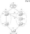
- FIG. 3 illustrates the nodes participating in a handover procedure between an E-UMTS system and a legacy UMTS system according to an exemplary embodiment of the present invention.
- a UE 310 which is connected to an E-UMTS system 370 and is receiving the service provided from a PDN 390 such as the IP network, is now moving to access a UMTS system 380 to receive service therefrom.
- the UE 310 is moving from the E-UMTS system 370 to the UMTS system 380 in the handover area where it can receive signals from both the E-UMTS system 370 and the UMTS system 380.
- the forward/reverse transmission path for packet data changes from an old path of UE (310) - E-RAN (320) - E-CN (330) - PDN (390) to a new path of UE (310) - RNC (340) - SGSN (350) - GGSN (360) - PDN (390) or to another new path of UE (310) - RNC (340) - SGSN (350) - E-CN (330) - PDN (390) after the handover.
- the UE 310 which is connected to the UMTS system 380 and is receiving the service provided from the PDN 390, is now moving to access the E-UMTS system 370 to receive service therefrom.
- the UE 310 is moving from the UMTS system 380 to the E-UMTS system 370 in the handover area where it can receive signals from both the E-UMTS system 370 and the UMTS system 380.
- the forward/reverse transmission path for packet data changes from an old path of UE (310) - RNC (340) - SGSN (350) - GGSN (360) - PDN (390) to a new path of UE (310) - E-RAN (320) - E-CN (330) - PDN (390) after the handover.
- Node B(s) between the RNC 340 and the UE 310 in the UMTS system 380, and Node B(s) between the E-RAN 320 and the UE 310 in E-UMTS system 370 are not closely related to an operation of an exemplary embodiment of the present invention.
- the E-CN 330 may have connections 365 and 355 between the GGSN 360 and the SGSN 350.
- a first exemplary embodiment of the present invention sets up a tunnel between the E-CN 330 and the GGSN 360 and transmits user data through the tunnel so that the UE 310 may use its old IP address even after the handover.
- the data transmission path of FIG. 3 is given as PDN (390) - E-CN (330) - GGSN (360) - SGSN (350) - RNC (340) - UE (310) after the handover.
- Inter-node signaling for handover can advantageously support inter-system handover without modification of the SGSN and the RNC of the legacy UMTS system, by making the best use of the messages for an inter-SGSN Serving Radio Network System (SRNS) relocation procedure defined in the legacy UMTS system.
- SRNS Inter-SGSN Serving Radio Network System
- FIG. 4 illustrates a handover process according to a first exemplary embodiment of the present invention.
- the prefixes 's' and 't' attached to a name of each of the nodes indicate Source and Target, respectively.
- a UE 401 connected to an E-UMTS system measures quality information such as received power level or received signal strength of a UMTS system.
- the UE 401 sends a Measurement report message including the quality information of the UMTS system to an E-RAN 402.
- the E-RAN 402 determines whether to perform inter-RAT handover. After determining to perform inter-RAT handover, the E-RAN 402 sends a Handover required message to an E-CN 403 in step 412.
- the Handover required message includes 'Source RNC to Target RNC transparent container' used in an SRNS relocation process of the legacy UMTS system, and a desired target cell ID. That is, the E-RAN 402 configures the 'Source RNC (402) to Target RNC (406) transparent container' such that a target RNC 406 can understand it.
- the transparent container is used for inter-SGSN relocation. Even though the transparent container is forwarded from a source RNC to a target RNC via a core network, the core network does not open the container to check its contents.
- the following information is included in the 'Source RNC to Target RNC transparent container': RRC container, Iu interface's number (for example, '1' indicates Iu-PS), relocation type (always set to UE involved), integrity protection/encryption information, target cell ID, trace recording session info, and Multimedia Broadcast/ Multicast Service (MBMS) Linking info.
- the RRC container may include an RRC message provided from the UE 401, such as a Measurement report message.
- the E-CN 403 operates as a virtual SGSN by emulating a function of a SGSN and sends an inter-RAT HO request message to a GGSN 404.
- the E-CN 403 receives an inter-RAT HO response message in response thereto.
- the inter-RAT HO request message includes a packet data protocol context containing service/ subscriber information such as IP address and a quality of service (QoS) class allocated to the UE 401 in the E-UMTS system, and a UE-id.
- service/ subscriber information such as IP address and a quality of service (QoS) class allocated to the UE 401 in the E-UMTS system
- QoS quality of service
- the inter-RAT HO request/response messages include a GGSN address used to set up a User Plane (UP) data tunnel between the E-CN 403 and the GGSN 404.
- a tunnel is established between the E-CN 403 and the GGSN 404 through the information exchanged in steps 413 and 414. If the E-CN 403 is previously aware of the GGSN 404 (for example, there is only one GGSN in the system), steps 413 and 414 may be omitted.
- the E-CN 403 identifies an SGSN 405 to which a Handover command should be sent, using the target cell ID received in step 412.
- the E-CN 403 sends a Forward Relocation Request message to the identified SGSN 405.
- the Forward Relocation Request message includes the transparent container and the target cell ID received in step 412, and a Packet Data Protocol (PDP) context and a Mobility Management (MM) context generated by the E-CN 403.
- the SGSN 405 sends a Relocation request message to an RNC 406.
- the SGSN 405 receives a Relocation request acknowledgement (Ack) message in response to the sent message.
- the RNC 406 allocates resources to the UE 401 and then sends the Relocation request Ack message to the SGSN 405.
- Ack Relocation request acknowledgement
- the SGSN 405 sends a Forward Relocation Response message to the E-CN 403 in response to the Forward Relocation Request message.
- the Relocation request Ack message and the Forward Relocation Response message include 'DRNC to SRNC transparent container' and Radio Access Bearer (RAB) setup/failed list.
- the 'DRNC to SRNC transparent container' includes an RRC message in an RRC container.
- the RAB setup/failed list includes Radio Bearer (RB) information used for an access to the RNC 406.
- RB Radio Bearer
- the RAB setup list ('RAB to setup list') includes IDs and QoS information of normally set-up RABs among the RABs requested to be set up
- the RAB failed list ('RAB failed to setup list') includes IDs of RABs failed to be normally set up among the requested RABs.
- the messages exchanged in steps 416 to 419 may use the intact message formats used in the inter-SGSN SRNS relocation procedure in the legacy UMTS system. Also, steps 413 to 415 and steps 416 to 419 may occur together without order.
- user data is initially forwarded in step 420 from the E-CN 403 to the GGSN 404 through the tunnel established in step 415.
- Data forwarding may be initiated in step 420 and in step 432.
- the E-CN 403 forwards a Handover command message to the UE 401 via the E-RAN 402.
- the Handover command message includes the RB information provided from the UMTS system in step 419.
- the UE 401 changes the RAT from OFDM to CDMA.
- the UE 401 performs uplink (UL)/downlink (DL) synchronization with the RNC 406 according to CDMA. If the UE 401 and the RNC 406 detect each other in steps 425 and 426, respectively, then the RNC 406 sends a Relocation detect message indicating the detection of the UE 401 to the SGSN 405 in step 427. If the UE 401 sends an RRC message for requesting RRC connection to the RNC 406 in step 428, the RNC 406 sends a Relocation complete message to the SGSN 405 in step 429. In steps 430 and 431, the SGSN 405 sends a Forward Relocation Complete message to the E-CN 403, and receives a Forward Relocation Complete Ack message in response to the forward relocation complete message.
- UL uplink
- DL downlink
- the E-CN 403 may change a data transmission path for the UE 401 so that it includes the GGSN 404 and not the E-RAN 402.
- the SGSN 405 sends an Update PDP context request message to the GGSN 404, and then receives an Update PDP context response message in response to the Update PDP context request message.
- a Routing Area Update procedure is performed between the UE 401 and the RNC 406, enabling communication between the UE 401 and the RNC 406.
- a second exemplary embodiment of the present invention sets up a tunnel between the E-CN 330 and the SGSN 350 and transmits user data through the tunnel as the E-CN 330 serves as the GGSN 360, so that the UE 310 may use its old IP address even after the handover.
- the data transmission path after the handover is given as PDN (390) - E-CN (330) - SGSN (350) - RNC (340) - UE (310).
- Inter-node signaling for handover may advantageously support inter-system handover without modification of the SGSN and the RNC of the legacy UMTS system as the E-CN 330 almost serves as the GGSN 360, by efficiently using the inter-SGSN SRNS relocation procedure defined in the legacy UMTS system.
- FIG. 5 illustrates a handover process according to a second exemplary embodiment of the present invention.
- the prefixes 's' and 't' attached to the name of each of the nodes indicate Source and Target, respectively.
- a UE 451 connected to an E-UMTS system measures quality information such as received power level or received signal strength of a UMTS system, and sends a Measurement report message including the quality information for the UMTS system to an E-RAN 452.
- the E-RAN 452 determines whether to perform inter-RAT handover. After determining to perform inter-RAT handover, the E-RAN 452 sends a Handover required message to an E-CN 453 in step 462.
- the Handover required message includes 'Source RNC to Target RNC transparent container' used in an SRNS relocation process of the legacy UMTS system, and a desired target cell ID. That is, the E-RAN 452 generates the 'Source RNC to Target RNC transparent container' so that a target RNC 456 can understand it, and contains the Measurement report message from the UE 451 in the transparent container.
- the transparent container is used for inter-SGSN relocation. Even though the transparent container is forwarded from a source RNC to a target RNC via a core network, the core network does not open the container to check its contents.
- the following information is included in the 'Source RNC to Target RNC transparent container': RRC container, Iu interface's number (for example, '1' indicates Iu-PS), relocation type (always set to UE involved), integrity protection/encryption information, target cell ID, trace recording session info and Multimedia Broadcast/ Multicast Service (MBMS) Linking info.
- the E-CN 453 In step 463, the E-CN 453 generates a PDP context and an MM context, such as, PDP/MM context, associated with the UE 451, in order to operate as a virtual SGSN of the legacy UMTS system.
- the PDP context includes service/subscriber information such as IP address and a QoS class allocated to the UE 451 in the E-UMTS system.
- the E-CN 453 can spontaneously generate the MM context and the PDP context. Alternatively, the E-CN 453 can acquire from the UE 451 the information necessary to generate the MM context and the PDP context.
- the E-CN 453 sends a message for inquiring the information necessary for generating the MM context and the PDP context to the UE 451, and receives a message containing the information necessary for generating the MM context and the PDP context from the UE 451 in response thereto.
- the E-CN 453 identifies an SGSN 455 to which a Handover command should be sent, using the target cell ID received in step 462, and sends a Forward Relocation Request message to the identified SGSN 455.
- the Forward Relocation Request message includes the transparent container and the target cell ID received in step 462, together with the PDP context and the MM context generated in step 463.
- the PDP context includes a GGSN address to facilitate the identification of an appropriate GGSN by the SGSN 455.
- the PDP context includes an address of the E-CN 453 as the GGSN address so that the SGSN 455 may recognize the E-CN 453 as a virtual GGSN. In this way, a data tunnel is directly opened between the E-CN 453 and the SGSN 455 without passing through the GGSN 454.
- the SGSN 455 sends a Relocation request message to an RNC 456.
- the RNC 456 allocates resources to the UE 451 and then sends the Relocation request Ack message to the SGSN 455.
- the Relocation request Ack message includes a 'DRNC to SRNC transparent container'.
- the SGSN 455 sends a Forward Relocation Response message to the E-CN 453 in response to the Forward Relocation Request message.
- the Relocation request Ack message and the Forward Relocation Response message include the 'DRNC to SRNC transparent container' and RAB setup/failed list.
- the RAB setup/ failed list includes RB information used access the RNC 456.
- the RAB setup list includes IDs and QoS information corresponding to normally set-up RABs among the RABs requested to be set up.
- the RAB failed list includes IDs of RABs fail ed to be normally set up among the requested RABs.
- the messages exchanged in steps 464 to 467 may use the intact message formats used in the inter-SGSN SRNS relocation procedure in the legacy UMTS system.
- user data is initially forwarded in step 468 from the E-CN 453 to the SGSN 455 through the data tunnel set up after step 464.
- Data may be initially forwarded in step 468 and in step 480.
- the E-CN 453 forwards a Handover command message to the UE 451 via the E-RAN 452.
- the Handover command message includes the RB information provided from the UMTS system in step 467, and the 'DRNC to SRNC transparent container'.
- the UE 451 upon receipt of the Handover command message, changes the RAT from OFDM to CDMA.
- the UE 451 performs UL/DL synchronization with the RNC 456 according to CDMA. If the UE 451 and the RNC 456 detect each other in steps 473 and 474, respectively, then the RNC 456 sends a Relocation detect message indicating the detection of the UE 451 to the SGSN 455 in step 475. If the UE 451 sends an RRC message to the RNC 456 according to the information contained in the 'DRNC to SRNC transparent container' in step 476, the RNC 456 sends a Relocation complete message to the SGSN 455 in step 477. In steps 478 and 479, the SGSN 455 sends a Forward Relocation Complete message to the E-CN 453, and receives a Forward Relocation Complete Ack message in response to the Forward Relocation Complete message.
- step 480 the E-CN 453 changes a data transmission path for the UE 451 so that it includes the SGSN 455 and not the E-RAN 452.
- steps 481 and 482 if necessary, the SGSN 455 sends an Update PDP context request message to the E-CN 453, and then receives an Update PDP context response message in response to the Update PDP context request message.
- step 483 a Routing Area Update procedure is performed between the UE 451 and the E-CN 453, enabling communication between the UE 451 and the RNC 456.
- the foregoing method performs the inter-node signaling for handover without changing IP addresses of UEs 401 and 451 in communication, by efficiently using the inter-SGSN SRNS relocation procedure of the legacy UMTS system. Therefore, the exemplary embodiments of the present invention can use the legacy SGSN and RNC without modification.
- FIG. 6 illustrates a structure of a UE according to the first and second exemplary embodiments of the present invention.
- reference numerals 510 and 530 represent a UMTS message transceiver and an E-UMTS message transceiver, respectively.
- the UMTS message transceiver 510 and the E-UMTS message transceiver 530 exchange the messages based on at least one of the exemplary embodiments of the present invention between the UMTS system and the E-UMTS system.
- the UMTS message transceiver 510 and the E-UMTS message transceiver 530 are connected to a message handler 520.
- the UMTS message transceiver 510 and the E-UMTS message transceiver 530 communicate with the UMTS system and the E-UMTS system through radio frequency (RF) units capable of processing OFDM signals and CDMA signals in frequency bands of the UMTS system and the E-UMTS system.
- RF radio frequency
- the message handler 520 generates messages to be transmitted to the UMTS system and the E-UMTS system, and forwards the generated messages to the UMTS message transceiver 510 and the E-UMTS message transceiver 530. Further, the message handler 520 analyzes the messages received from the UMTS system and the E-UMTS system via the UMTS message transceiver 510 and the E-UMTS message transceiver 530, and performs a necessary operation, especially a handover-related operation.
- a UMTS signal strength measurer 540 measures strength of the signal received from the currently connected system, such as the UMTS system. If the measured signal strength is higher than or equal to a threshold, the UMTS signal strength measurer 540 provides quality information indicating the measured signal strength to the message handler 520 to enable the start of handover.
- FIG. 7 illustrates an operation of a UE according to the first and second exemplary embodiments of the present invention.
- a UMTS signal measurer 540 measures strength of a signal received from the UMTS system. If the measured signal strength is higher than or equal to a threshold, the UMTS signal measurer 540 provides quality information indicating the measured signal strength to a message handler 520. The message handler 520 generates a Measurement report message (step 410) including the quality information. The Measurement report message is forwarded to the E-UMTS system by an E-UMTS message transceiver 530.
- step 620 If it is determined in step 620 that the E-UMTS message transceiver 530 receives a Handover command message (step 422), the UE proceeds to step 630. Otherwise, the UE returns to step 610.
- step 630 upon receipt of the Handover command message, the UE changes the RAT of its RF unit (not shown) from E-UMTS (OFDM) to UMTS (CDMA).
- step 640 the UE performs an inter-SGSN SRNS relocation procedure (steps 424 to 435) with the UMTS system using the message handler 520 and a UMTS message transceiver 510.
- FIG. 8 illustrates a structure of an E-RAN according to the first and second exemplary embodiments of the present invention.
- a radio message transceiver 710 which handles communication with a UE, receives a Measurement report message (step 410) from the UE, and sends a Handover command message (step 422) to the UE.
- a handover decider 740 is a unit that determines whether to perform handover of the UE based on quality information included in the Measurement report message provided from the radio message transceiver 710. The handover decider 740 determines whether there is a need for inter-RAT handover taking into account a moving direction of the UE and a load of each cell.
- the handover decider 740 sends a notification indicating the need for handover to a message handler 720.
- the message handler 720 generates messages to be sent to the UE or the E-CN, and analyzes the messages received from the UE or the E-CN.
- a network message transceiver 730 handles message exchange with the E-CN according to at least one of the exemplary embodiments of the present invention by sending a Handover required message (step 412) to the E-CN and receiving a Handover command message (step 421) from the E-CN.
- FIG. 9 illustrates an operation of an E-RAN according to the first and second exemplary embodiments of the present invention.
- a radio message transceiver 710 receives a Measurement report message (step 410) from a UE.
- a handover decider 740 determines whether there is a need for inter-RAT handover according to quality information of the UMTS system included in the Measurement report message (step 411). For example, if the signal strength of the UMTS system is higher than or equal to a threshold, the handover decider 740 determines that there is a need for inter-RAT han dover.
- a message handler 720 If it is determined that there is a need for handover, a message handler 720 generates in step 830 a Handover required message (step 412), and the Handover required message is sent to an E-CN by a network message transceiver 730.
- the Handover required message includes 'Source RNC to Target RNC transparent container'.
- the network message transceiver 730 waits for a Handover command message (step 421) to be received from the E-CN.
- the message handler 720 Upon receipt of the Handover command message in step 840, the message handler 720 generates in step 850 a Handover command message (step 422) to be sent to the UE based on the Handover command message.
- the generated Handover command message is forwarded to the UE by the radio message transceiver 710.
- FIG. 10 illustrates a structure of an E-CN according to the first and second exemplary embodiments of the present invention.
- three message transceivers 910, 930 and 940 handle message exchanges with an E-RAN, an SGSN and a GGSN, respectively, and are connected to a message handler 920.
- the message handler 920 generates messages to be sent from an E-CN to other nodes according to at least one of the exemplary embodiments of the present invention, and analyzes the messages incoming from the other nodes.
- Data transceivers 950 and 960 each exchange user data with an external network of a PDN and the GGSN.
- the E-CN forwards the downlink data received from the PDN via the data transceiver-for-PDN 950, to the E-RAN via a data transceiver-for-E-RAN (not shown).
- the message transceiver 940 receives an inter-RAT HO response message (step 414) including GGSN address information from the GGSN
- tunnel controller 970 establishes a tunnel for a user plane using the GGSN address information.
- data packets can flow along the path of PDN - E-CN - (Tunnel) - GGSN - SGSN - RNC - UE.
- the E-CN forwards the downlink data received from the PDN via the data transceiver-for-PDN 950, to the E-RAN via the data transceiver-for-E-RAN (not shown).
- the tunnel controller 970 establishes a tunnel for a user plane to the SGSN.
- data packets can flow along the path of PDN - E-CN - (Tunnel) - SGSN - RNC - UE.
- the data transceiver 960 transmits the downlink data from the data transceiver 950 to the GGSN or the SGSN.
- FIG. 11 illustrates an operation of an E-CN according to the first exemplary embodiment of the present invention.
- a message handler 920 After a message transceiver 910 receives a Handover required message (step 412) from an E-RAN in step 1002, a message handler 920 generates an inter-RAT HO request message (step 413) and the inter-RAT HO request message is sent to a GGSN by a message transceiver 940 in step 1004.
- the inter-RAT HO request message may include information on the tunnel over which the E-CN will forward user data in the future, and such information as PDP context and UE-id.
- a message transceiver 930 sends a Forward Relocation Request message (step 416) generated by the message handler 920 to an SGSN.
- the Forward Relocation Request message can be equal to the message format used in the inter-SGSN SRNS relocation procedure in the legacy UMTS system. Therefore, the message handler 920 of the E-CN is capable of emulating the message generation function of the SGSN.
- steps 1004 and 1006 are replaceable with each other.
- the message transceiver 940 After sending the inter-RAT HO request message and the Forward Relocation Request message, the message transceiver 940 waits for an inter-RAT HO response message from the GGSN in response to the inter-RAT HO request message in step 1008, and the message transceiver 930 waits for a Forward Relocation Response message from the SGSN in response to the Forward Relocation Request message in step 1012.
- a tunnel controller 970 Upon receipt of the inter-RAT HO response message in step 1008, a tunnel controller 970 establishes a tunnel for user plane (i.e. user tunnel) to the GGSN in step 1010. If the Forward Relocation Response message is received in step 1012, the message transceiver 910 forwards a Handover command message generated by the message handler 920 to the E-RAN in step 1014.
- user plane i.e. user tunnel
- the E-CN determines in step 1016 whether there is any UE-related tunnel already established to the GGSN. If there is no tunnel to the GGSN, the E-CN returns to step 1008 to wait until the tunnel to the GGSN is set up. However, if there is a tunnel established to the GGSN, the E-CN waits for a Forward Relocation Complete message to be received from the SGSN using the message transceiver 930 in step 1020. Upon receipt of the Forward Relocation Complete message, the message transceiver 930 sends a Forward Relocation Complete Ack message (step 431) generated by the message handler 920 to the SGSN in step 1022.
- the E-CN can start forwarding downlink data via the data tunnel to the GGSN (step 1018) after step 1016, or start forwarding downlink data via the data tunnel to the GGSN (step 1024) after step 1022.
- FIG. 12 illustrates an operation of an E-CN according to the second exemplary embodiment of the present invention.
- a message transceiver 910 receives a Handover required message (step 452) from an E-RAN in step 1032, and a message transceiver 930 sends a Forward Relocation Request message (step 464) generated by a message handler 920 to an SGSN in step 1034.
- the Forward Relocation Request message can be equal to the message format used in the inter-SGSN SRNS relocation procedure in the legacy UMTS system. Therefore, the message handler 920 of the E-CN is capable of emulating the message generation function of the SGSN.
- the Forward Relocation Request message includes a PDP context and an MM context, and the message handler 920 sets a GGSN address included in the PDP context as an E-CN address so that the SGSN may recognize the E-CN as a virtual GGSN.
- a message transceiver 940 waits for a Forward Relocation Response message from the SGSN in response to the Forward Relocation Request message in step 1036.
- a tunnel controller 970 establishes a tunnel for a user plane to the SGSN in step 1038.
- the E-CN starts data forwarding to the SGSN.
- step 1040 is optional. If the Forwarding Relocation Response message is received in step 1038, the message transceiver 910 forwards a Handover command message generated by the message handler 920 to the E-RAN in step 1042.
- the E-CN After sending the Handover command message to the E-RAN, the E-CN waits for a Forward Relocation Complete message to be received from the SGSN at the message transceiver 930 in step 1044. Upon receipt of the Forward Relocation Complete message, the message transceiver 930 sends a Forward Relocation Complete Ack message (step 431) generated by the message handler 920 to the SGSN in step 1046.
- the E-CN can forward downlink data via the data tunnel to the SGSN (step 1040) between steps 1038 and 1042, or forward downlink data via the data tunnel to the SGSN (step 1048) after step 1046.
- FIG. 13 illustrates a structure of a GGSN according to the first and second exemplary embodiments of the present invention.
- a message handler 1120 handles E-CN related messages according to at least one of the foregoing embodiments, and a message transceiver 1110 exchanges the messages with the E-CN.
- Reference numeral 1130 represents a legacy GGSN function unit, and the legacy GGSN function unit 1130 serves as a GGSN of the legacy UMTS system. That is, the GGSN according to the exemplary embodiment of the present invention exchanges messages with the E-CN, in addition to the function of the legacy GGSN.
- FIG. 14 illustrates an operation of a GGSN according to the first exemplary embodiment of the present invention.
- a message transceiver 1110 upon receipt of an inter-RAT HO request message from an E-CN in step 1210, sends an inter-RAT HO response message generated by a message handler 1120 to the E-CN in step 1220.
- the inter-RAT HO response message includes a GGSN address and a port number related to a user tunnel so that the E-CN can establish the user tunnel to the GGSN. If downlink user data is received from the E-CN via the user tunnel in step 1230, a legacy GGSN function unit 1130 handles the downlink user data as data forwarded from the external PDN in step 1240.
- a third exemplary embodiment of the present invention is provided for handover from a UMTS system to an E-UMTS system.
- an E-CN establishes a data tunnel to an SGSN and transmits user data through the tunnel by performing a function of an SGSN of the legacy UMTS system.
- the data transmission path after the handover according to the third embodiment is given as PDN (390) - GGSN (360) - E-CN (330) - E-RNC (320) - UE (310).
- Inter-node signaling for handover supports inter-system handover without modification of the GGSN, the SGSN and the RNC of the legacy UMTS system as the E-CN almost perfectly serves as the GGSN, by making the best use of the inter-SGSN SRNS relocation procedure defined in the legacy UMTS system.
- FIG. 15 illustrates a handover process according to the third exemplary embodiment of the present invention.
- the prefixes 's' and 't' attached to a name of each of the nodes indicate Source and Target, respectively.
- a UE 1301 connected to a UMTS system measures quality information such as received power level or received signal strength of an E-UMTS system.
- the UE 1301 sends a Measurement report message including the quality information of the E-UMTS system to an RNC 1302.
- the RNC 1302 determines whether to perform handover. After determining to perform handover, the RNC 1302 sends a Relocation required message to an SGSN 1303 in step 1312.
- the Relocation required message similar to the handover in the legacy UMTS system, includes a target cell ID and 'Source RNC to Target RNC transparent container'.
- the SGSN 1303 determines that it should perform the inter-SGSN SRNS relocation procedure according to the target cell ID included in the Relocation required message.
- the SGSN 1303 sends a Forward Relocation Request message to an E-CN 1305.
- the SGSN 1303 sends a Forward Relocation Request message used for the general inter-SGSN SRNC relocation to the E-CN 1305, considering that the E-CN 1305 is another SGSN of the UMTS system.
- the Forward Relocation Request message includes GGSN address, 'Source RNC to Target RNC transparent container', RAB to setup list, MM context, and PDP context.
- step 1314 the E-CN 1305 reanalyzes RAB information, (i.e., RAB setup list), included in the Forward Relocation Request message as user plane (UP) bearer information used in the E-UMTS system.
- RAB information i.e., RAB setup list
- UP user plane
- step 1315 the E-CN 1305 sets up a UP bearer to an E-RAN 1306.
- step 1319 the E-CN 1305 sets up a UP data tunnel to a GGSN 1304 based on the GGSN address included in the Forward Relocation Request message.
- the E-CN 1305 sends in step 1316 a Forward Relocation Response message to the SGSN 1303 in response to the Forward Relocation Request message.
- the Forward Relocation Response message includes 'Target RNC to Source RNC transparent container'.
- the E-CN 1305 perfectly emulates the target SGSN that sends the Forward Relocation Response message in the inter-SGSN SRNS relocation procedure.
- step 1317 the SGSN 1303 sends a Relocation command message to the RNC 1302 in response to the Forward Relocation Response message.
- step 1318 the RNC 1302 reads 'DRNC to SRNC transparent container' included in the Relocation command message, and sends an RRC message included in the transparent container to the UE 1301 using a Relocation command message.
- the UE 1301 changes RAT from CDMA to OFDM in response to the Relocation command message.
- the UE 1301 performs UL/DL synchronization with the tE-RAN 1306 including the E-RAN. If the UE 1301 and the tE-RAN 1306 detect each other in steps 1322 and 1323, respectively, then the UE 1301 camps in the target cell covered by the E-RAN in step 1324.
- the following steps 1325 to 1328 provide a process in which the E-CN 1305 emulates the function of the target SGSN in the inter-SGSN SRNS relocation procedure.
- the E-CN 1305 sends to the source SGSN 1303 a Forward Relocation Complete message indicating the normal completion of the inter-SGSN SRNC relocation, and then receives a Forward Relocation Complete Ack message from the SGSN 1303.
- the E-CN 1305 sends an Update PDP context request message to request the GGSN 1304 to modify its PDP context depending on the possible change in the QoS information, and receives an Update PDP context response message from the GGSN 1304.
- a Routing Area Update procedure is performed between the UE 1301, the E-CN 1305 and the GGSN 1304, to enable communication between the UE 1301 and the E-RAN 1306.
- the data transmission path becomes GGSN - E-CN - E-RNC - UE.
- the IP address allocated to the UE remains unchanged.
Claims (6)
- Procédé d'exécution d'un transfert intercellulaire d'un système de communication mobile à modulation par répartition de fréquence orthogonale, OFDM, à un système universel de télécommunication mobile, UMTS, basé sur accès multiples par répartition de code, CDMA, par un équipement d'utilisateur, UE, en communication avec un réseau de données en paquets, PDN, par l'intermédiaire du système de communication mobile OFDM, caractérisé en ce qu'il comprend les étapes de :la mesure (410) de la force de signal du système UMTS, etla transmission (410) d'un message de rapport de mesure indiquant la force de signal mesurée au système de communication mobile OFDM,caractérisé parla réception (422) d'un message de commande de transfert intercellulaire comprenant les informations de support radio, RB, en provenance d'un réseau central amélioré, E-CN ; etl'accès (428) au système UMTS en utilisant des informations RB,dans lequel un réseau d'accès radio amélioré, E-RAN, du système de communication mobile OFDM détermine qu'il faut effectuer un transfert intercellulaire du système de communication mobile OFDM au système UMTS sur la base de la force de signal mesurée, ettransmet, à un réseau central amélioré, E-CN, du système de communication mobile OFDM, un message de transfert intercellulaire requis comprenant un conteneur transparent d'organe de commande de réseau radio, RNC, source à RNC cible ;dans lequel l'E-CN établit un tunnel entre l'E-CN et le GGSN,transmet un message de demande de relocalisation vers l'avant à un noeud de prise en charge de GPRS de desserte, SGSN, cible,dans lequel le SGSN cible transmet un message de demande de relocalisation à un organe de commande de réseau radio, RNC, cible,dans lequel le RNC cible alloue des informations de support radio, RB, et transmet les informations RB à l'E-CN par l'intermédiaire du SGSN cible.
- Procédé selon la revendication 1, dans lequel le message de demande de relocalisation vers l'avant comprend un contexte de gestion de mobilité, MM.
- Procédé selon la revendication 1, dans lequel le message de commande de transfert intercellulaire comprend le conteneur transparent de RNC cible à RNC source.
- Système d'exécution d'un transfert intercellulaire d'un système de communication mobile à modulation par répartition de fréquence orthogonale, OFDM, à un système universel de télécommunication mobile, UMTS, basé sur accès multiples par répartition de code, CDMA, par un équipement d'utilisateur, UE, en communication avec un réseau de données en paquets, PDN, par l'intermédiaire du système de communication mobile OFDM, caractérisé en ce qu'il comprend :l'UE (401), agencé pour effectuer la mesure, en communication avec un réseau de données en paquets, PDN, par l'intermédiaire du système de communication mobile OFDM, de la force de signal du système UMTS, et la transmission d'un message de rapport de mesure indiquant la force de signal mesurée au système de communication mobile OFDM,caractérisé en ce que ledit UE est agencé pour effectuer la réception d'un message de commande de transfert intercellulaire comprenant les informations de support radio, RB, en provenance d'un réseau central amélioré, E-CN, et l'accès au système UMTS en utilisant des informations RB,dans lequel un réseau d'accès radio amélioré, E-RAN, (402) du système de communication mobile OFDM est agencé pour effectuer la détermination qu'il faut effectuer un transfert intercellulaire du système de communication mobile OFDM au système UMTS sur la base de la force de signal mesurée, et la transmission, à un réseau central amélioré, E-CN, (403) du système de communication mobile OFDM, d'un message de transfert intercellulaire requis comprenant un conteneur transparent d'organe de commande de réseau radio, RNC, source à RNC cible ;dans lequel l'E-CN est agencé pour effectuer l'établissement d'un tunnel entre l'E-CN et un noeud de prise en charge de GPRS de passerelle, GGSN, et la transmission d'un message de demande de relocalisation vers l'avant à un noeud de prise en charge de GPRS de desserte, SGSN, cible (405),dans lequel le SGSN cible (405) est agencé pour effectuer la transmission d'un message de demande de relocalisation à un organe de commande de réseau radio, RNC, cible (406), etdans lequel le RNC cible (406) est agencé pour effectuer l'allocation des informations de support radio, RB, et la transmission des informations RB à l'E-CN (403) par l'intermédiaire du SGSN cible (405).
- Système selon la revendication 4, dans lequel le message de demande de relocalisation vers l'avant comprend un contexte de gestion de mobilité, MM.
- Système selon la revendication 4, dans lequel le message de commande de transfert intercellulaire comprend un conteneur transparent de RNC cible à RNC source.
Applications Claiming Priority (3)
| Application Number | Priority Date | Filing Date | Title |
|---|---|---|---|
| KR20050061392 | 2005-07-07 | ||
| KR1020050114863A KR101042763B1 (ko) | 2005-07-07 | 2005-11-29 | 이기종 시스템 간의 핸드오버 방법 및 장치 |
| PCT/KR2006/002664 WO2007007990A1 (fr) | 2005-07-07 | 2006-07-07 | Appareil et procede de transfert entre des systemes differents |
Publications (3)
| Publication Number | Publication Date |
|---|---|
| EP1911178A1 EP1911178A1 (fr) | 2008-04-16 |
| EP1911178A4 EP1911178A4 (fr) | 2012-08-29 |
| EP1911178B1 true EP1911178B1 (fr) | 2017-11-08 |
Family
ID=37637325
Family Applications (1)
| Application Number | Title | Priority Date | Filing Date |
|---|---|---|---|
| EP06769206.1A Active EP1911178B1 (fr) | 2005-07-07 | 2006-07-07 | Appareil et procédé de transfert entre des systèmes différents |
Country Status (5)
| Country | Link |
|---|---|
| US (1) | US7953042B2 (fr) |
| EP (1) | EP1911178B1 (fr) |
| AU (1) | AU2006267255B2 (fr) |
| CA (1) | CA2611962C (fr) |
| WO (1) | WO2007007990A1 (fr) |
Families Citing this family (81)
| Publication number | Priority date | Publication date | Assignee | Title |
|---|---|---|---|---|
| DE10243142A1 (de) * | 2002-09-17 | 2004-03-18 | Siemens Ag | Verfahren zur Durchführung einer Übergabeprozedur in einem Funkkommunikationssystem für eine paketvermittelte Verbindung und dafür angepasstes Funkkommunikationssystem |
| US8553643B2 (en) | 2005-07-19 | 2013-10-08 | Qualcomm Incorporated | Inter-system handover using legacy interface |
| US8064400B2 (en) | 2005-07-20 | 2011-11-22 | Interdigital Technology Corporation | Method and system for supporting an evolved UTRAN |
| KR100810207B1 (ko) * | 2005-07-22 | 2008-03-06 | 삼성전자주식회사 | 패킷 교환 기반의 네트워크에서 코어 네트워크 개체들 간의핸드오버 방법 및 장치 |
| CN101128043B (zh) | 2006-08-15 | 2011-02-02 | 华为技术有限公司 | 系统间切换或者改变时的数据处理方法 |
| JP5340948B2 (ja) | 2006-10-31 | 2013-11-13 | クゥアルコム・インコーポレイテッド | Eノードb間のハンドオーバ手順 |
| US8797995B2 (en) * | 2007-01-18 | 2014-08-05 | Cisco Technology, Inc. | Device-assisted layer 3 handoff for mobile services |
| TWI459835B (zh) * | 2007-02-12 | 2014-11-01 | Interdigital Tech Corp | 自lte/eutran交接至gprs/geran支援方法及裝置 |
| CA2678102C (fr) * | 2007-02-12 | 2014-09-23 | Interdigital Technology Corporation | Procede et appareil servant a supporter un transfert intercellulaire d'un gprs/geran a un eutran lte |
| WO2008110093A1 (fr) * | 2007-03-09 | 2008-09-18 | Huawei Technologies Co., Ltd. | Procédé et dispositif pour qu'un réseau d'accès gère des ressources radio |
| KR101017458B1 (ko) * | 2007-03-12 | 2011-02-25 | 닛본 덴끼 가부시끼가이샤 | 이동 통신 시스템 및 통신 제어 방법 |
| US8289920B2 (en) * | 2007-03-16 | 2012-10-16 | Qualcomm Incorporated | Method and apparatus for handoff between access systems |
| US8576795B2 (en) | 2007-03-16 | 2013-11-05 | Qualcomm Incorporated | Method and apparatus for handoff between source and target access systems |
| CN107182096A (zh) * | 2007-03-16 | 2017-09-19 | 高通股份有限公司 | 用于接入系统之间的切换的方法和装置 |
| KR100965724B1 (ko) * | 2007-03-23 | 2010-06-24 | 삼성전자주식회사 | 이종의 무선 통신 네트워크에서 핸드오버 장치 및 방법 |
| CN101272315B (zh) * | 2007-03-23 | 2011-04-06 | 华为技术有限公司 | 分组数据包传输方法、系统和网络设备 |
| EP1983789A1 (fr) * | 2007-04-17 | 2008-10-22 | Nokia Siemens Networks Oy | Redirection des services dans des systèmes de communication évolués |
| US8331314B2 (en) * | 2007-04-20 | 2012-12-11 | Telefonaktiebolaget L M Ericsson (Publ) | Dormant session management associated with handover |
| WO2008133476A1 (fr) * | 2007-04-30 | 2008-11-06 | Lg Electronics Inc. | Procédé et procédures pour le réglage de support radio |
| CN101309500B (zh) | 2007-05-15 | 2011-07-20 | 华为技术有限公司 | 不同无线接入技术间切换时安全协商的方法和装置 |
| US9049629B2 (en) * | 2007-06-18 | 2015-06-02 | Qualcomm Incorporated | Method and apparatus for fast inter-system handover |
| US8259673B2 (en) * | 2007-06-19 | 2012-09-04 | Telefonaktiebolaget L M Ericsson (Publ) | System and method for providing voice service in a mobile network with multiple wireless technologies |
| US9392504B2 (en) * | 2007-06-19 | 2016-07-12 | Qualcomm Incorporated | Delivery of handover command |
| US8620320B2 (en) * | 2007-06-19 | 2013-12-31 | Motorola Mobility Llc | Methods for handing over calls between communication networks using dissimilar air interfaces |
| US8094620B2 (en) * | 2007-06-26 | 2012-01-10 | Telefonaktiebolaget L M Ericsson (Publ) | System and method for providing voice service in a multimedia mobile network |
| EP2019564A1 (fr) * | 2007-06-26 | 2009-01-28 | Nokia Siemens Networks Oy | Appareil pour contòler le transfert d'appel |
| EP2031921A1 (fr) * | 2007-08-14 | 2009-03-04 | Alcatel Lucent | Appareil et procédé pour la manipulation d'informations de capacité de terminal mobile |
| EP2026618B1 (fr) * | 2007-08-14 | 2012-08-01 | Alcatel Lucent | Procédé et appareil de transfert d'appel avec transmission des données d'un noeud de source vers un noeud cible dans un réseau de télécommunications sans fil |
| US8780856B2 (en) * | 2007-09-18 | 2014-07-15 | Telefonaktiebolaget Lm Ericsson (Publ) | Inter-system handoffs in multi-access environments |
| JP4733093B2 (ja) * | 2007-09-28 | 2011-07-27 | 株式会社エヌ・ティ・ティ・ドコモ | 無線通信システム及び無線通信方法 |
| GB2454650A (en) | 2007-10-29 | 2009-05-20 | Nec Corp | Resource Allocation for persistently allocated resources |
| WO2009057684A1 (fr) * | 2007-10-30 | 2009-05-07 | Ntt Docomo, Inc. | Procédé de communication mobile et station de base radio |
| CN101431780B (zh) * | 2007-11-09 | 2010-12-22 | 华为技术有限公司 | 一种实现网络优化切换的方法、设备及系统 |
| KR20090073443A (ko) * | 2007-12-31 | 2009-07-03 | 엘지전자 주식회사 | 이기종망간 핸드 오버 방법 |
| US8755793B2 (en) | 2008-01-04 | 2014-06-17 | Qualcomm Incorporated | Apparatus and methods to facilitate seamless handoffs between wireless communication networks |
| CN101978767B (zh) * | 2008-01-31 | 2013-11-20 | 爱立信电话股份有限公司 | 移动端接的呼叫的电路交换回退 |
| WO2009113928A1 (fr) * | 2008-03-13 | 2009-09-17 | Telefonaktiebolaget L M Ericsson (Publ) | Procédure de transfert basée sur la qualité entre cellules co-localisées |
| CN101541050B (zh) * | 2008-03-17 | 2011-01-05 | 大唐移动通信设备有限公司 | 一种用户设备在系统间切换后默认连接的处理方法及装置 |
| GB2458886A (en) | 2008-03-25 | 2009-10-07 | Nec Corp | Inter-network handover request message incorporating identifier of target gateway component |
| JP5298356B2 (ja) * | 2008-03-31 | 2013-09-25 | インテル・コーポレーション | WiMAXネットワークと他のネットワークとの間における相互作用およびハンドオーバー |
| CN101448287B (zh) * | 2008-04-04 | 2011-10-26 | 中兴通讯股份有限公司 | 一种激活状态下用户设备跨接入网切换的实现方法 |
| US8638749B2 (en) * | 2008-06-06 | 2014-01-28 | Qualcomm Incorporated | Method and apparatus for inter-network handoff |
| WO2009157742A2 (fr) * | 2008-06-27 | 2009-12-30 | 주식회사 케이티 | Procédé et système de traitement des transferts dans un réseau mixte à protocole de mobilité hétérogène et dispositif client mip |
| KR101028330B1 (ko) * | 2008-06-27 | 2011-04-12 | 주식회사 케이티 | 이종 이동성 프로토콜 혼재망에서의 핸드오버 처리 방법 및 그 시스템과 mip 클라이언트 장치 |
| US8391239B2 (en) * | 2008-09-22 | 2013-03-05 | Qualcomm Incorporated | Bearer count alignment during inter-rat handover |
| US20100098021A1 (en) * | 2008-10-16 | 2010-04-22 | Cisco Technology, Inc. | Policy-driven layer 3 handoff for mobile services |
| EP2214444A1 (fr) | 2009-01-30 | 2010-08-04 | Nec Corporation | Procédé pour l'optimisation de la réduction de la signalisation de la mobilité au moment du changement inter-rat |
| US9042340B2 (en) * | 2009-02-10 | 2015-05-26 | Nokia Corporation | Method, apparatus and computer program product for transfer of capability support information in a multi-rat environment |
| US8743722B2 (en) * | 2009-03-26 | 2014-06-03 | Kyocera Corporation | Radio terminal, radio communication system, and radio base station |
| GB2469645A (en) * | 2009-04-20 | 2010-10-27 | Nec Corp | Providing information about a mobile device in a relocation request message |
| CN101959215B (zh) * | 2009-07-17 | 2014-06-04 | 华为技术有限公司 | 分组业务数据的传输方法、装置和系统 |
| US8638711B2 (en) * | 2009-08-11 | 2014-01-28 | Qualcomm Incorporated | Systems and methods of maintaining core network status during serving radio network subsystem relocation |
| GB2472800A (en) | 2009-08-18 | 2011-02-23 | Nec Corp | System for ensuring the core network is aware of the aggregated number of unsuccessfully transmitted downlink data packets for a mobile device |
| KR101078639B1 (ko) * | 2009-09-30 | 2011-11-01 | 삼성전자주식회사 | 이종 망간의 핸드오버 장치 및 그 방법 |
| US8957938B2 (en) * | 2009-10-28 | 2015-02-17 | Alcatel Lucent | Method and apparatus for handing over a video conversation from packet switch domain to circuit switch domain |
| CN102387491B (zh) * | 2010-08-27 | 2015-09-16 | 中兴通讯股份有限公司 | 一种信令跟踪方法及装置 |
| US20120115479A1 (en) * | 2010-10-12 | 2012-05-10 | Bo Ehrenholm | Method and Network Node |
| CN102457924B (zh) | 2010-10-21 | 2014-12-03 | 华为技术有限公司 | 一种多载波的切换方法和装置 |
| CN102142990B (zh) * | 2010-12-31 | 2016-11-02 | 华为技术有限公司 | 业务用量监控方法及设备 |
| US20120238264A1 (en) * | 2011-03-18 | 2012-09-20 | Stoke, Inc. | Method and apparatus to support seamless mobility across offload gateways |
| US8576756B2 (en) | 2011-06-28 | 2013-11-05 | International Business Machines Corporation | Continuous cache service in cellular networks |
| US20130208642A1 (en) * | 2011-08-10 | 2013-08-15 | Spidercloud Wireless, Inc. | Method and apparatus for topology management for handovers in heterogeneous networks |
| JP5742624B2 (ja) * | 2011-09-22 | 2015-07-01 | 富士通株式会社 | 基地局 |
| WO2013100826A1 (fr) * | 2011-12-27 | 2013-07-04 | Telefonaktiebolaget L M Ericsson (Publ) | Procédé dans un nœud de réseau radio permettant de commander l'utilisation de rat et la largeur de bande de fréquences dans un système de radiocommunication |
| US8885752B2 (en) | 2012-07-27 | 2014-11-11 | Intel Corporation | Method and apparatus for feedback in 3D MIMO wireless systems |
| KR20140046169A (ko) * | 2012-10-10 | 2014-04-18 | 삼성전자주식회사 | 무선 통신 시스템에서 셀 구성 장치 및 방법 |
| US20140126535A1 (en) * | 2012-11-07 | 2014-05-08 | Telefonaktiebolaget L M Ericsson (Publ) | Bss derived information for cs to ps srvcc |
| US9832717B2 (en) | 2012-12-19 | 2017-11-28 | Blackberry Limited | Method and apparatus for layer 3 configuration in a heterogeneous network |
| US9072021B2 (en) | 2012-12-19 | 2015-06-30 | Blackberry Limited | Method and apparatus for hybrid automatic repeat request operation in a heterogeneous network architecture |
| US9036578B2 (en) | 2012-12-19 | 2015-05-19 | Blackberry Limited | Method and apparatus for control channel configuration in a heterogeneous network architecture |
| US9271324B2 (en) | 2012-12-19 | 2016-02-23 | Blackberry Limited | Method and apparatus for assisted serving cell configuration in a heterogeneous network architecture |
| CN104247504B (zh) | 2013-04-16 | 2018-05-11 | 华为技术有限公司 | 小区切换方法及设备 |
| EP3005757A1 (fr) * | 2013-05-29 | 2016-04-13 | Telefonaktiebolaget LM Ericsson (publ) | Identification d'un équipement utilisateur dans un réseau de communication |
| CN104735734B (zh) * | 2013-12-19 | 2019-07-30 | 中兴通讯股份有限公司 | 一种业务处理的方法、网络控制器及转发设备 |
| US9763148B2 (en) | 2015-05-04 | 2017-09-12 | At&T Intellectual Property I, L.P. | Method and system for managing wireless connectivity in a communication system |
| US10257078B2 (en) | 2016-04-01 | 2019-04-09 | Qualcomm Incorporated | Interworking with legacy radio access technologies for connectivity to next generation core network |
| CN109479225B (zh) * | 2016-07-29 | 2020-11-17 | 华为技术有限公司 | 一种接入异制式小区的方法以及相关设备 |
| EP3531747B1 (fr) * | 2016-10-27 | 2021-02-24 | Huawei Technologies Co., Ltd. | Procédé et dispositif de communication |
| CN111183675B (zh) * | 2018-01-03 | 2021-12-21 | Oppo广东移动通信有限公司 | 一种系统间切换的方法和装置 |
| KR102160005B1 (ko) | 2019-04-18 | 2020-09-25 | 한국전자통신연구원 | 이동통신 시스템에서 핸드오버 동안의 저지연 데이터 전송 방법 및 이를 위한 장치 |
| US10979399B2 (en) | 2019-05-24 | 2021-04-13 | Sierra Nevada Corporation | Unified communication gateway systems |
Family Cites Families (20)
| Publication number | Priority date | Publication date | Assignee | Title |
|---|---|---|---|---|
| US5483664A (en) | 1993-07-26 | 1996-01-09 | Motorola, Inc. | Cellular communications with scheduled handoffs |
| FI105993B (fi) * | 1997-08-20 | 2000-10-31 | Nokia Mobile Phones Ltd | Menetelmä ja järjestelmä radiotiedonsiirtoverkon hallitsemiseksi ja radioverkko-ohjain |
| EP1147679B1 (fr) * | 1999-01-25 | 2003-05-07 | Nokia Corporation | Interconnexion entre differents reseaux d'acces radio |
| GB9918636D0 (en) * | 1999-08-06 | 1999-10-13 | Nokia Telecommunications Oy | Inter-system handover |
| US6771964B1 (en) * | 1999-09-24 | 2004-08-03 | Nokia Networks | Handover between wireless telecommunication networks/systems |
| GB2359220A (en) * | 2000-02-03 | 2001-08-15 | Orange Personal Comm Serv Ltd | Handover in accordance with a network policy |
| US6836471B2 (en) * | 2001-02-02 | 2004-12-28 | Nokia Mobile Phones Ltd. | Method and system for inter-operator handover between WCDMA and GSM |
| US7181218B2 (en) * | 2001-04-10 | 2007-02-20 | Telefonaktiebolaget Lm Ericsson (Publ) | Commanding handover between differing radio access technologies |
| ATE350868T1 (de) * | 2001-05-10 | 2007-01-15 | Nortel Networks Ltd | System und verfahren zur umleitung von kommunikation zwischen mobiltelekommunikationsnetzen mit unterschiedlichen funkzugangstechnologien |
| JP4412604B2 (ja) * | 2002-06-06 | 2010-02-10 | トムソン ライセンシング | 無線lanおよび移動体通信システム間の相互接続をサポートする方法および装置 |
| AU2003234667A1 (en) * | 2002-06-06 | 2003-12-22 | Thomson Licensing S.A. | Wlan as a logical support node (sgsn) for interworking between the wlan and a mobile communications system |
| US20040203787A1 (en) | 2002-06-28 | 2004-10-14 | Siamak Naghian | System and method for reverse handover in mobile mesh Ad-Hoc networks |
| US20040105413A1 (en) | 2002-07-02 | 2004-06-03 | Interdigital Technology Corporation | System and method for tight inter-working between wireless local area network (WLAN) and universal mobile telecommunication systems (UMTS) |
| KR100810332B1 (ko) * | 2002-12-05 | 2008-03-04 | 삼성전자주식회사 | 서로 다른 이동통신시스템들 사이의 핸드오버 장치 및 방법 |
| KR20050036521A (ko) * | 2003-10-16 | 2005-04-20 | 삼성전자주식회사 | 주파수도약 직교주파수분할다중화 기반의이동통신시스템에서의 핸드오버 방법 |
| US7321570B2 (en) * | 2004-02-03 | 2008-01-22 | Motorola, Inc. | Method and apparatus for dynamic power allocation to a multimedia broadcast/multicast service |
| US7733831B2 (en) * | 2004-08-23 | 2010-06-08 | Alcatel-Lucent Usa Inc. | Detecting a wireless network air interface |
| US7167459B2 (en) * | 2004-12-30 | 2007-01-23 | Motorola, Inc. | Inter-network handover in a packet radio system |
| US8315633B2 (en) * | 2005-08-26 | 2012-11-20 | Qualcomm Incorporated | Uplink soft handoff support in UMTS TDD systems for efficient uplink power and rate control |
| WO2007103369A2 (fr) * | 2006-03-07 | 2007-09-13 | Interdigital Technology Corporation | Procédé et appareil pour la prise en charge du transfert intercellulaire dans un système de communication sans fil lte gtp |
-
2006
- 2006-07-07 AU AU2006267255A patent/AU2006267255B2/en active Active
- 2006-07-07 US US11/482,109 patent/US7953042B2/en active Active
- 2006-07-07 EP EP06769206.1A patent/EP1911178B1/fr active Active
- 2006-07-07 CA CA2611962A patent/CA2611962C/fr active Active
- 2006-07-07 WO PCT/KR2006/002664 patent/WO2007007990A1/fr active Application Filing
Non-Patent Citations (1)
| Title |
|---|
| None * |
Also Published As
| Publication number | Publication date |
|---|---|
| EP1911178A1 (fr) | 2008-04-16 |
| WO2007007990A1 (fr) | 2007-01-18 |
| EP1911178A4 (fr) | 2012-08-29 |
| CA2611962A1 (fr) | 2007-01-18 |
| CA2611962C (fr) | 2013-08-27 |
| US20070036109A1 (en) | 2007-02-15 |
| AU2006267255A1 (en) | 2007-01-18 |
| US7953042B2 (en) | 2011-05-31 |
| AU2006267255B2 (en) | 2010-03-04 |
Similar Documents
| Publication | Publication Date | Title |
|---|---|---|
| EP1911178B1 (fr) | Appareil et procédé de transfert entre des systèmes différents | |
| JP4886079B2 (ja) | 異種システム間のハンドオーバー方法 | |
| KR101093846B1 (ko) | 회선 교환 호와 패킷 교환 호 사이의 핸드오버를 수행하기 위한 방법, 장치 및 컴퓨터 판독 가능한 매체 | |
| RU2358413C1 (ru) | Устройство и способ выбора сетевого интерфейса в мобильном терминале, поддерживающем схему множественного беспроводного доступа | |
| RU2287912C2 (ru) | Система связи, содержащая множество сетей связи | |
| CN103957568B (zh) | 一种方法及无线发射/接收单元 | |
| US8358627B2 (en) | Radio communication system, radio communication method, and mobile station | |
| US20060221903A1 (en) | Communication connection control mechanism in a core network ordered access change scenario | |
| US20080013553A1 (en) | Activation of multiple bearer services in a long term evolution system | |
| KR100680749B1 (ko) | 이종 무선 네트워크를 사용하는 셀룰러 통신 시스템에서의핸드오버 장치 및 방법 | |
| JP2006526356A (ja) | Wcdmaシステムのサービス品質を利用したハンドオーバー設定方法及びシステム | |
| JP2012531091A (ja) | ソースサービングゲートウェイとターゲットサービングゲートウェイとの間でパケットを転送するインターネットワーキング技術 | |
| IL204284A (en) | Method and device for requesting point-to-point protocol cases from the Pact Science Services Network | |
| KR100701797B1 (ko) | 비인가 무선망 및 씨디엠에이 이동통신망 융합 서비스시스템에서의 호 처리 및 핸드오프 처리 방법 | |
| JP2009512300A (ja) | セルラー式移動無線通信システムにおけるセルラー間転送を改良する方法 | |
| TW200805974A (en) | Activation of multiple bearer services in a long term evolution system | |
| EP2019564A1 (fr) | Appareil pour contòler le transfert d'appel | |
| KR100589953B1 (ko) | 비동기 이동통신망으로부터 동기 이동통신망으로의핸드오버 방법 | |
| KR20090098536A (ko) | 패킷 데이터 서비스를 위한 데이터 접속 방법, 그를 위한데이터 서비스 시스템, 데이터 접속 관리 서브시스템 및단말기 | |
| KR20150025890A (ko) | 이동통신망에서의 핸드오버 제어 방법 및 그 장치 | |
| KR20090090409A (ko) | 이종망간의 모바일 아이피 핸드오버 방법 및 그 시스템 | |
| KR20050048194A (ko) | 발신 응답 대기중 비동기 이동통신망으로부터 동기이동통신망으로의 핸드오버 방법 |
Legal Events
| Date | Code | Title | Description |
|---|---|---|---|
| PUAI | Public reference made under article 153(3) epc to a published international application that has entered the european phase |
Free format text: ORIGINAL CODE: 0009012 |
|
| 17P | Request for examination filed |
Effective date: 20080207 |
|
| AK | Designated contracting states |
Kind code of ref document: A1 Designated state(s): AT BE BG CH CY CZ DE DK EE ES FI FR GB GR HU IE IS IT LI LT LU LV MC NL PL PT RO SE SI SK TR |
|
| DAX | Request for extension of the european patent (deleted) | ||
| A4 | Supplementary search report drawn up and despatched |
Effective date: 20120727 |
|
| RIC1 | Information provided on ipc code assigned before grant |
Ipc: H04W 36/00 20090101AFI20120723BHEP Ipc: H04B 7/26 20060101ALI20120723BHEP |
|
| RAP1 | Party data changed (applicant data changed or rights of an application transferred) |
Owner name: SAMSUNG ELECTRONICS CO., LTD. |
|
| STAA | Information on the status of an ep patent application or granted ep patent |
Free format text: STATUS: EXAMINATION IS IN PROGRESS |
|
| 17Q | First examination report despatched |
Effective date: 20161107 |
|
| REG | Reference to a national code |
Ref country code: DE Ref legal event code: R079 Ref document number: 602006054055 Country of ref document: DE Free format text: PREVIOUS MAIN CLASS: H04B0007260000 Ipc: H04W0036000000 |
|
| GRAP | Despatch of communication of intention to grant a patent |
Free format text: ORIGINAL CODE: EPIDOSNIGR1 |
|
| STAA | Information on the status of an ep patent application or granted ep patent |
Free format text: STATUS: GRANT OF PATENT IS INTENDED |
|
| RIC1 | Information provided on ipc code assigned before grant |
Ipc: H04B 7/26 20060101ALI20170502BHEP Ipc: H04W 36/14 20090101ALN20170502BHEP Ipc: H04W 36/00 20090101AFI20170502BHEP Ipc: H04W 76/04 20090101ALN20170502BHEP Ipc: H04W 92/02 20090101ALN20170502BHEP |
|
| INTG | Intention to grant announced |
Effective date: 20170526 |
|
| RIC1 | Information provided on ipc code assigned before grant |
Ipc: H04W 76/04 20090101ALN20170516BHEP Ipc: H04W 36/14 20090101ALN20170516BHEP Ipc: H04W 92/02 20090101ALN20170516BHEP Ipc: H04B 7/26 20060101ALI20170516BHEP Ipc: H04W 36/00 20090101AFI20170516BHEP |
|
| GRAS | Grant fee paid |
Free format text: ORIGINAL CODE: EPIDOSNIGR3 |
|
| GRAA | (expected) grant |
Free format text: ORIGINAL CODE: 0009210 |
|
| STAA | Information on the status of an ep patent application or granted ep patent |
Free format text: STATUS: THE PATENT HAS BEEN GRANTED |
|
| AK | Designated contracting states |
Kind code of ref document: B1 Designated state(s): AT BE BG CH CY CZ DE DK EE ES FI FR GB GR HU IE IS IT LI LT LU LV MC NL PL PT RO SE SI SK TR |
|
| REG | Reference to a national code |
Ref country code: GB Ref legal event code: FG4D |
|
| REG | Reference to a national code |
Ref country code: CH Ref legal event code: EP Ref country code: AT Ref legal event code: REF Ref document number: 945257 Country of ref document: AT Kind code of ref document: T Effective date: 20171115 |
|
| REG | Reference to a national code |
Ref country code: IE Ref legal event code: FG4D |
|
| REG | Reference to a national code |
Ref country code: DE Ref legal event code: R096 Ref document number: 602006054055 Country of ref document: DE |
|
| REG | Reference to a national code |
Ref country code: NL Ref legal event code: FP |
|
| REG | Reference to a national code |
Ref country code: LT Ref legal event code: MG4D |
|
| REG | Reference to a national code |
Ref country code: AT Ref legal event code: MK05 Ref document number: 945257 Country of ref document: AT Kind code of ref document: T Effective date: 20171108 |
|
| PG25 | Lapsed in a contracting state [announced via postgrant information from national office to epo] |
Ref country code: FI Free format text: LAPSE BECAUSE OF FAILURE TO SUBMIT A TRANSLATION OF THE DESCRIPTION OR TO PAY THE FEE WITHIN THE PRESCRIBED TIME-LIMIT Effective date: 20171108 Ref country code: LT Free format text: LAPSE BECAUSE OF FAILURE TO SUBMIT A TRANSLATION OF THE DESCRIPTION OR TO PAY THE FEE WITHIN THE PRESCRIBED TIME-LIMIT Effective date: 20171108 Ref country code: SE Free format text: LAPSE BECAUSE OF FAILURE TO SUBMIT A TRANSLATION OF THE DESCRIPTION OR TO PAY THE FEE WITHIN THE PRESCRIBED TIME-LIMIT Effective date: 20171108 Ref country code: ES Free format text: LAPSE BECAUSE OF FAILURE TO SUBMIT A TRANSLATION OF THE DESCRIPTION OR TO PAY THE FEE WITHIN THE PRESCRIBED TIME-LIMIT Effective date: 20171108 |
|
| PG25 | Lapsed in a contracting state [announced via postgrant information from national office to epo] |
Ref country code: BG Free format text: LAPSE BECAUSE OF FAILURE TO SUBMIT A TRANSLATION OF THE DESCRIPTION OR TO PAY THE FEE WITHIN THE PRESCRIBED TIME-LIMIT Effective date: 20180208 Ref country code: GR Free format text: LAPSE BECAUSE OF FAILURE TO SUBMIT A TRANSLATION OF THE DESCRIPTION OR TO PAY THE FEE WITHIN THE PRESCRIBED TIME-LIMIT Effective date: 20180209 Ref country code: LV Free format text: LAPSE BECAUSE OF FAILURE TO SUBMIT A TRANSLATION OF THE DESCRIPTION OR TO PAY THE FEE WITHIN THE PRESCRIBED TIME-LIMIT Effective date: 20171108 Ref country code: AT Free format text: LAPSE BECAUSE OF FAILURE TO SUBMIT A TRANSLATION OF THE DESCRIPTION OR TO PAY THE FEE WITHIN THE PRESCRIBED TIME-LIMIT Effective date: 20171108 Ref country code: IS Free format text: LAPSE BECAUSE OF FAILURE TO SUBMIT A TRANSLATION OF THE DESCRIPTION OR TO PAY THE FEE WITHIN THE PRESCRIBED TIME-LIMIT Effective date: 20180308 |
|
| REG | Reference to a national code |
Ref country code: FR Ref legal event code: PLFP Year of fee payment: 13 |
|
| PG25 | Lapsed in a contracting state [announced via postgrant information from national office to epo] |
Ref country code: DK Free format text: LAPSE BECAUSE OF FAILURE TO SUBMIT A TRANSLATION OF THE DESCRIPTION OR TO PAY THE FEE WITHIN THE PRESCRIBED TIME-LIMIT Effective date: 20171108 Ref country code: SK Free format text: LAPSE BECAUSE OF FAILURE TO SUBMIT A TRANSLATION OF THE DESCRIPTION OR TO PAY THE FEE WITHIN THE PRESCRIBED TIME-LIMIT Effective date: 20171108 Ref country code: CZ Free format text: LAPSE BECAUSE OF FAILURE TO SUBMIT A TRANSLATION OF THE DESCRIPTION OR TO PAY THE FEE WITHIN THE PRESCRIBED TIME-LIMIT Effective date: 20171108 Ref country code: CY Free format text: LAPSE BECAUSE OF FAILURE TO SUBMIT A TRANSLATION OF THE DESCRIPTION OR TO PAY THE FEE WITHIN THE PRESCRIBED TIME-LIMIT Effective date: 20171108 Ref country code: EE Free format text: LAPSE BECAUSE OF FAILURE TO SUBMIT A TRANSLATION OF THE DESCRIPTION OR TO PAY THE FEE WITHIN THE PRESCRIBED TIME-LIMIT Effective date: 20171108 |
|
| REG | Reference to a national code |
Ref country code: DE Ref legal event code: R097 Ref document number: 602006054055 Country of ref document: DE |
|
| PG25 | Lapsed in a contracting state [announced via postgrant information from national office to epo] |
Ref country code: PL Free format text: LAPSE BECAUSE OF FAILURE TO SUBMIT A TRANSLATION OF THE DESCRIPTION OR TO PAY THE FEE WITHIN THE PRESCRIBED TIME-LIMIT Effective date: 20171108 Ref country code: RO Free format text: LAPSE BECAUSE OF FAILURE TO SUBMIT A TRANSLATION OF THE DESCRIPTION OR TO PAY THE FEE WITHIN THE PRESCRIBED TIME-LIMIT Effective date: 20171108 |
|
| PLBE | No opposition filed within time limit |
Free format text: ORIGINAL CODE: 0009261 |
|
| STAA | Information on the status of an ep patent application or granted ep patent |
Free format text: STATUS: NO OPPOSITION FILED WITHIN TIME LIMIT |
|
| 26N | No opposition filed |
Effective date: 20180809 |
|
| PG25 | Lapsed in a contracting state [announced via postgrant information from national office to epo] |
Ref country code: SI Free format text: LAPSE BECAUSE OF FAILURE TO SUBMIT A TRANSLATION OF THE DESCRIPTION OR TO PAY THE FEE WITHIN THE PRESCRIBED TIME-LIMIT Effective date: 20171108 |
|
| REG | Reference to a national code |
Ref country code: CH Ref legal event code: PL |
|
| PG25 | Lapsed in a contracting state [announced via postgrant information from national office to epo] |
Ref country code: LU Free format text: LAPSE BECAUSE OF NON-PAYMENT OF DUE FEES Effective date: 20180707 Ref country code: MC Free format text: LAPSE BECAUSE OF FAILURE TO SUBMIT A TRANSLATION OF THE DESCRIPTION OR TO PAY THE FEE WITHIN THE PRESCRIBED TIME-LIMIT Effective date: 20171108 |
|
| REG | Reference to a national code |
Ref country code: BE Ref legal event code: MM Effective date: 20180731 |
|
| REG | Reference to a national code |
Ref country code: IE Ref legal event code: MM4A |
|
| PG25 | Lapsed in a contracting state [announced via postgrant information from national office to epo] |
Ref country code: LI Free format text: LAPSE BECAUSE OF NON-PAYMENT OF DUE FEES Effective date: 20180731 Ref country code: IE Free format text: LAPSE BECAUSE OF NON-PAYMENT OF DUE FEES Effective date: 20180707 Ref country code: CH Free format text: LAPSE BECAUSE OF NON-PAYMENT OF DUE FEES Effective date: 20180731 |
|
| PG25 | Lapsed in a contracting state [announced via postgrant information from national office to epo] |
Ref country code: BE Free format text: LAPSE BECAUSE OF NON-PAYMENT OF DUE FEES Effective date: 20180731 |
|
| REG | Reference to a national code |
Ref country code: GB Ref legal event code: 732E Free format text: REGISTERED BETWEEN 20190530 AND 20190605 |
|
| REG | Reference to a national code |
Ref country code: DE Ref legal event code: R082 Ref document number: 602006054055 Country of ref document: DE Representative=s name: PAGE, WHITE & FARRER GERMANY LLP, DE Ref country code: DE Ref legal event code: R081 Ref document number: 602006054055 Country of ref document: DE Owner name: NOKIA TECHNOLOGIES OY, FI Free format text: FORMER OWNER: SAMSUNG ELECTRONICS CO., LTD., SUWON-SI, GYEONGGI-DO, KR |
|
| REG | Reference to a national code |
Ref country code: NL Ref legal event code: PD Owner name: NOKIA TECHNOLOGIES OY; FI Free format text: DETAILS ASSIGNMENT: CHANGE OF OWNER(S), ASSIGNMENT; FORMER OWNER NAME: SAMSUNG ELECTRONICS CO., LTD. Effective date: 20191119 |
|
| PG25 | Lapsed in a contracting state [announced via postgrant information from national office to epo] |
Ref country code: TR Free format text: LAPSE BECAUSE OF FAILURE TO SUBMIT A TRANSLATION OF THE DESCRIPTION OR TO PAY THE FEE WITHIN THE PRESCRIBED TIME-LIMIT Effective date: 20171108 |
|
| PG25 | Lapsed in a contracting state [announced via postgrant information from national office to epo] |
Ref country code: HU Free format text: LAPSE BECAUSE OF FAILURE TO SUBMIT A TRANSLATION OF THE DESCRIPTION OR TO PAY THE FEE WITHIN THE PRESCRIBED TIME-LIMIT; INVALID AB INITIO Effective date: 20060707 Ref country code: PT Free format text: LAPSE BECAUSE OF FAILURE TO SUBMIT A TRANSLATION OF THE DESCRIPTION OR TO PAY THE FEE WITHIN THE PRESCRIBED TIME-LIMIT Effective date: 20171108 |
|
| PGFP | Annual fee paid to national office [announced via postgrant information from national office to epo] |
Ref country code: NL Payment date: 20230614 Year of fee payment: 18 Ref country code: IT Payment date: 20230612 Year of fee payment: 18 Ref country code: FR Payment date: 20230620 Year of fee payment: 18 |
|
| PGFP | Annual fee paid to national office [announced via postgrant information from national office to epo] |
Ref country code: GB Payment date: 20230601 Year of fee payment: 18 |
|
| PGFP | Annual fee paid to national office [announced via postgrant information from national office to epo] |
Ref country code: DE Payment date: 20230531 Year of fee payment: 18 |