EP1910798B1 - Method and apparatus for centering an ophthalmic lens - Google Patents
Method and apparatus for centering an ophthalmic lens Download PDFInfo
- Publication number
- EP1910798B1 EP1910798B1 EP06776469A EP06776469A EP1910798B1 EP 1910798 B1 EP1910798 B1 EP 1910798B1 EP 06776469 A EP06776469 A EP 06776469A EP 06776469 A EP06776469 A EP 06776469A EP 1910798 B1 EP1910798 B1 EP 1910798B1
- Authority
- EP
- European Patent Office
- Prior art keywords
- concave trough
- ophthalmic lens
- liquid
- lens
- gripper
- Prior art date
- Legal status (The legal status is an assumption and is not a legal conclusion. Google has not performed a legal analysis and makes no representation as to the accuracy of the status listed.)
- Active
Links
Images


Classifications
-
- G—PHYSICS
- G01—MEASURING; TESTING
- G01M—TESTING STATIC OR DYNAMIC BALANCE OF MACHINES OR STRUCTURES; TESTING OF STRUCTURES OR APPARATUS, NOT OTHERWISE PROVIDED FOR
- G01M11/00—Testing of optical apparatus; Testing structures by optical methods not otherwise provided for
- G01M11/02—Testing optical properties
- G01M11/0207—Details of measuring devices
Definitions
- the present invention deals with a method and an apparatus for centering an ophthalmic lens in a concave trough of an inspection cell. In a further aspect, the present invention also deals with a method and an apparatus for removing an ophthalmic lens from a concave trough of an inspection cell.
- Contact lenses which are worn only once and are then disposed of are known to be produced in a highly automated production process with the aid of reusable molds.
- the contact lenses produced are optically inspected.
- soft contact lenses are difficult to handle using mechanical means, and accordingly it has been suggested to insert the soft contact lenses into a water bath where they are optically inspected. It has been found that a contact lens, when inserted into a water bath, always orients itself with the concave surface facing upwards. This property is made use of in optical inspection of the lenses.
- the inspection cell has the form of a cuvette having a concave trough for accommodating the contact lens to be inspected, and a channel being in communication with the concave trough.
- the cuvette is filled with a liquid, e.g. water.
- the cuvette can be swiveled between a handling position, in which the contact lens can be inserted into the liquid through the channel or removed from the concave trough through the channel, and an inspection position, in which the contact lens is inspected. In the inspection position, the contact lens is inspected through a viewing glass of the cuvette.
- the amount of liquid in the cuvette is chosen such, that during inspection the underside of the viewing glass is fully immersed in the liquid so that no bubbles can be formed between the liquid and the viewing glass, thus reliably avoiding any influencing of the optical system by bubbles or free boundary surfaces.
- the contact lens is first inserted through the channel into the liquid. It is then allowed to orient itself and settle down in the concave trough. The contact lens automatically settles down in a centered position in the concave trough.
- the cuvette is swiveled to the inspection position thus causing the lens to move from the center of the concave trough to a continuation of the concave trough, which continuation can form a part of an optical lens through which the contact lens can be inspected.
- the cuvette is swiveled back to the handling position, thus causing the lens to move back towards the center of the concave trough.
- this swiveling back of the cuvette does not in all cases result in the contact lens being centered again in the concave trough.
- a gripper may comprise a gripper head with an attachment surface being provided with specifically arranged holes through which suction may be applied to make the lens adhere to the attachment surface of the gripper head.
- suction may be applied to make the lens adhere to the attachment surface of the gripper head.
- the gripper head is lowered through the channel until it reaches the contact lens. Suction is then applied, and the gripper with the lens adhering to the attachment surface is then raised again through the channel.
- the lens adhering to the attachment surface of the gripper can then be transported by moving the gripper to a further station in the manufacturing process.
- the lens can be transported to a package having a concave bowl into the center of which the contact lens is then laid down.
- the contact lens to be removed from the cuvette is not properly centered in the concave trough of the cuvette after swiveling back the cuvette from the inspection position to the handling position.
- the gripper is then lowered towards the center of the concave trough (where the contact lens should rest) and the contact lens is arranged off-center, application of suction through the holes may result in water being drawn in through holes not covered by the contact lens into the suction channel of the gripper and further into the vacuum source generating the suction.
- the vacuum source must then be cleaned, or even worse the water drawn in may be detrimental to the vacuum source, or more expensive vacuum sources must be used having a water separator.
- the contact lens due to the contact lens not being attached to the gripper head in a centered position, the contact lens cannot be properly laid down into the center of the concave bowl of the package, which is desirable to keep the overall volume of the package small and to avoid damaging of the lens during sealing of the package with a foil.
- This objective is achieved by a method for centering an ophthalmic lens, e.g. a contact lens, in a concave trough of an inspection cell, as it is characterized by the features of independent claim 1, and by an apparatus for centering an ophthalmic lens, e.g. a contact lens, in the concave trough of an inspection cell, as it is characterized by the features of independent claim 6.
- Advantageous embodiments of the method and apparatus are the subject of the respective dependent claims.
- a further aspect of the invention relates to a method and an apparatus for the removal of an ophthalmic lens from the concave trough of an inspection cell, as they are characterized by the features of claims 4, 5 or 10.
- the method according to the invention comprises the steps of
- the first step causes the off-centered lens to be whirled up, so that the lens leaves its off-centered position.
- the lens is allowed to settle down again.
- the settling down of the lens automatically occurs such that the lens settles down in the center of the concave trough, similar to what happens when the lens is introduced into the liquid in the inspection cell, e.g. a cuvette, prior to its inspection.
- the step of applying a pulse of a fluid to the liquid contained in the inspection cell generates only little expense from a technical point of view and the settling down of the lens occurs automatically, thus providing a simple solution to the problem of off-centered lenses.
- both the liquid contained in the inspection cell and the fluid applied to the liquid (contained in the inspection cell) in the form of a pulse are water. While it is in general conceivable that the fluid to be applied in form of a pulse could be a gaseous pulse, a liquid is preferred. Since a preferred liquid contained in the inspection cell is water, the liquid applied in form of a pulse is also water.
- the pulse of fluid is applied to the surface of the liquid contained in the channel. While it is in general conceivable that the pulse may be applied to the liquid at a location below the surface of the liquid, it is technically less expensive to provide a means (e.g. the open end of a capillary tube) which is arranged above the surface of the liquid contained in the inspection cell and which ejects a pulse of fluid, e.g. water, that impinges on the surface of the liquid.
- a means e.g. the open end of a capillary tube
- a further aspect of the invention relates to a method for removing an ophthalmic lens, e.g. a contact lens, from an inspection cell which is filled with liquid, through a channel of the cell which is in communication with the concave trough.
- the method comprises in particular the steps of
- This method allows to remove the ophthalmic lens from a centered position and to transfer it to another location with the lens adhering to the gripper in a centered position. In particular, it is thus possible to transfer the lens to a package and to lay it down into the center of a concave bowl of the package, which allows to use packages with minimum overall volume.
- the step of gripping the ophthalmic lens is performed by applying suction trough holes provided in an attachment surface of the gripper head thus causing the ophthalmic lens to be attached to the gripper head.
- the apparatus for centering the ophthalmic lens e.g. a contact lens
- the apparatus for centering the ophthalmic lens comprises means for applying a pulse of fluid to the liquid so as to whirl up the ophthalmic lens and to then allow it to settle down in the center of the concave trough.
- the means for applying the pulse of fluid to the liquid contained in the inspection cell comprise at least one capillary tube, the outlet end of which is arranged at a position above a set position of the channel of the inspection cell and facing towards the channel.
- a capillary tube is particularly advantageous inasmuch as once the pulse of liquid has been ejected through the end of the capillary tube, the capillary tube generates a "sucking" effect such that no droplets may rest at the outlet end of the capillary tube and may unintentionally fall down onto the inspection cell, e.g. the cuvette. Such unintentionally falling down droplets may otherwise contaminate the inspection cell, in particular the optics (e.g. the viewing glass) of the inspection cell.
- a further embodiment of the apparatus comprises a plurality of capillary tubes the outlet ends of which are each arranged at a position above a respective set position of a corresponding plurality of inspection cells and facing towards the channel of the respective inspection cell, and further comprising a common feed conduit to which the inlet ends of the capillary tubes are connected.
- the common feed conduit allows to only provide one single supply of fluid, e.g. water, to be connected to the feed conduit, which in turn supplies water to the various capillary tubes through their inlets ends connected to the conduit. This reduces the constructive expense of the apparatus.
- the ratio of the inner cross-section of the feed conduit to the inner cross-section of the outlet end of the capillary tube is at least 7:1, more preferably at least 10:1, and most preferably at least 20:1.
- the ratio of the inner cross-section of the feed-conduit to the inner cross-section of the outlet end of the capillary tube is high in order to achieve an even distribution of the flow and pressure to all of the capillary tubes connected to the feed conduit.
- the apparatus With respect to an apparatus for removing an ophthalmic lens, e.g. a contact lens, from an inspection cell which is filled with liquid, the apparatus in particular comprises
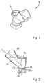
- Fig. 1 an embodiment of an inspection cell in form of a cuvette 1, as it is known, for example, from WO 01/016855 is shown in perspective view while Fig. 2 shows the inspection cell 1 in cross-sectional view in the inspection position.
- Cuvette 1 comprises a concave trough 10 having a continuation 100 and a channel 11 in communication with concave trough 10.
- a viewing glass 12 is provided through which inspection of the lens, e.g. a contact lens CL, can be performed.
- Continuation 100 of concave trough 10 is formed in the embodiment shown by an optical element 13 such as a lens, through which contact lens CL can be inspected in transmission.
- cuvette 1 is filled with liquid W, e.g. water, to a level L such that the level L of liquid W is above the underside of viewing glass 12, i.e. the underside of viewing glass 12 is fully immersed in the liquid W, so as to make sure that no bubbles can be formed between the liquid W and the underside of viewing glass 12 and that no boundary surfaces exist.
- liquid W e.g. water
- the optical inspection is not influenced by bubbles or boundary surfaces.
- a gripper 2 is shown comprising a gripper head 20 having holes 21 in its attachment surface 22.
- the gripper 2 is lowered through channel 11 of cuvette 1 until gripper head 20 reaches contact lens CL. Suction is then applied through holes 21 in order to make the contact lens adhere to attachment surface 22.
- gripper 2 is raised with contact lens CL being attached to attachment surface 22 of gripper head 20.
- contact lens CL may be slightly misplaced, i.e. it may be arranged slightly off-center. Since gripper head 20 is positioned accurately above the center of concave trough 10 of cuvette 1, lowering gripper 2 until gripper head 20 reaches contact lens CL and subsequently applying suction through holes 21 would result in liquid W being drawn in into the suction channel of gripper 2 and into the vacuum source (not shown) generating the suction. While such drawing in of liquid at best results in the need of cleaning the vacuum source, it may also have detrimental effects on the vacuum source, or a more expensive vacuum source having a water separator must be used so as to avoid damage to the vacuum source.
- a fluid pulse e.g. a pulse of water
- the fluid pulse P - represented by an arrow in Fig. 4 - may be applied through the outlet end 30 of a capillary tube 3.
- contact lens CL settles down automatically in the center of concave trough 10, as this is shown in Fig. 5 . Removal of contact lens CL from cuvette 1 can then be performed as this has been described above.
- Fig. 6 shows an embodiment of the apparatus according to the invention.
- the apparatus comprises a plurality of capillary tubes 3, the outlet ends 30 of which are arranged in a set position above the center of a corresponding plurality of cuvettes 1, as this is shown in Fig. 7 .
- the inlet ends 31 of the capillary tubes 3 are arranged in respective mounting elements 32 (see Fig. 6 ) which are accommodated by corresponding mounting elements 52 protruding from a common feed conduit 5.
- the outlet ends 30 of capillary tubes 3 are mounted to a mounting bar 6.
- a plurality of cuvettes 1 can be mounted to a respective carrier C.
- Feed conduit 5 is supplied with liquid (e.g. water) through a tube T.
- a valve V is arranged between tube T and feed conduit 5.
- feed conduit 5 as well as capillary tubes 3 have to be completely filled with liquid (initialization).
- the apparatus works as follows: At the time the carrier C carrying the cuvettes has reached its set position, that is to say at the time the cuvettes are arranged under the outlet ends 30 of capillary tubes 3 as shown in Fig. 7 , valve V ( Fig. 6 ) is opened for a short predetermined period of time, thus allowing pressurized fluid supplied through tube T to enter feed conduit 5.
- the supply of pressurized fluid presses a part of the fluid contained in feed conduit 5 into capillary tubes 3 which in turn causes fluid contained in capillary tubes 3 to be ejected through the outlet end thus generating the fluid pulse P (see Fig.
- valve V is closed again and, accordingly, no more fluid exits through outlet ends 30 of capillary tubes 3.
- the carrier C can then be moved to the next handling station, where a gripper can remove the contact lens CL from the centered position in the cuvette 1 (to which it has settled down, see Fig. 5 ), as has already been described hereinbefore.
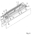
- mounting bar 6 is provided at each of its lateral ends with a first threaded pin 60, as can be seen in Fig. 8 , for allowing translatory movement (horizontal movement) of mounting bar 6 within slots 41 provided in lateral mounting flanges 40 (see also Fig. 7 ) of a mounting base 4 (see Fig. 6 ).
- Mounting bar 6 can be secured to flanges 40 with the aid of corresponding nuts 62 in order to fix its horizontal positional arrangement.
- Mounting bar 6 is further provided at each of its lateral ends with a pivot pin 63, about which mounting bar 6 can be pivoted in order to change the angle of the outlet end 30 of the capillary tubes 3 relative to the cuvettes 1. For example, it may be desirable to arrange the outlet ends in an angular orientation such that the pulse P (see Fig. 4 ) is applied to the liquid in the cuvettes under an angle other than 90°.
- mounting bar 6 further comprises at each of its lateral ends a fixation pin 64 which is guided in a curved slot 65 of a flange 66 (see also Fig. 6 ).
- the area of the inner cross-section of feed tube 5 - represented by diameter D shown in Fig.
- the pressurized liquid (e.g. water) supplied through tube T may, for example, be in the range between 2 bar to 3 bar, but can be adapted to the specific needs.
- the duration of a pulse P of liquid can be comparatively short, and may particularly be in the range of some hundred milliseconds. This is important inasmuch as the cycle time of a clock-cycled, highly automated manufacturing process is to be kept short in order to ensure a highly efficient manufacturing of contact lenses.
Landscapes
- Chemical & Material Sciences (AREA)
- Analytical Chemistry (AREA)
- Physics & Mathematics (AREA)
- General Physics & Mathematics (AREA)
- Eyeglasses (AREA)
- Optical Measuring Cells (AREA)
Abstract
Description
- The present invention deals with a method and an apparatus for centering an ophthalmic lens in a concave trough of an inspection cell. In a further aspect, the present invention also deals with a method and an apparatus for removing an ophthalmic lens from a concave trough of an inspection cell.
- Contact lenses which are worn only once and are then disposed of are known to be produced in a highly automated production process with the aid of reusable molds. In order to ensure that the quality of the lenses remains constantly at a very high level, the contact lenses produced are optically inspected. However, in particular soft contact lenses are difficult to handle using mechanical means, and accordingly it has been suggested to insert the soft contact lenses into a water bath where they are optically inspected. It has been found that a contact lens, when inserted into a water bath, always orients itself with the concave surface facing upwards. This property is made use of in optical inspection of the lenses.
- An inspection cell that can be used for the optical inspection of a contact lens in a water bath has been suggested in
WO 03/016855 - To inspect a contact lens, the contact lens is first inserted through the channel into the liquid. It is then allowed to orient itself and settle down in the concave trough. The contact lens automatically settles down in a centered position in the concave trough. For inspection, the cuvette is swiveled to the inspection position thus causing the lens to move from the center of the concave trough to a continuation of the concave trough, which continuation can form a part of an optical lens through which the contact lens can be inspected. Once the inspection of the lens has been completed, the cuvette is swiveled back to the handling position, thus causing the lens to move back towards the center of the concave trough. However, this swiveling back of the cuvette does not in all cases result in the contact lens being centered again in the concave trough.
- On the other hand, centering of the contact lens in the concave trough of the cuvette is important for the further handling of the contact lens. For example, once inspection of the contact lens has been completed it is typically removed from the concave trough by means of a gripper, as this is also disclosed in
WO 03/016855 - As already mentioned, it may occur that the contact lens to be removed from the cuvette is not properly centered in the concave trough of the cuvette after swiveling back the cuvette from the inspection position to the handling position. As the gripper is then lowered towards the center of the concave trough (where the contact lens should rest) and the contact lens is arranged off-center, application of suction through the holes may result in water being drawn in through holes not covered by the contact lens into the suction channel of the gripper and further into the vacuum source generating the suction. The vacuum source must then be cleaned, or even worse the water drawn in may be detrimental to the vacuum source, or more expensive vacuum sources must be used having a water separator. In addition, due to the contact lens not being attached to the gripper head in a centered position, the contact lens cannot be properly laid down into the center of the concave bowl of the package, which is desirable to keep the overall volume of the package small and to avoid damaging of the lens during sealing of the package with a foil.
- Accordingly, it is an objective of the instant invention to overcome the afore-mentioned disadvantages of the prior art.
- This objective is achieved by a method for centering an ophthalmic lens, e.g. a contact lens, in a concave trough of an inspection cell, as it is characterized by the features of
independent claim 1, and by an apparatus for centering an ophthalmic lens, e.g. a contact lens, in the concave trough of an inspection cell, as it is characterized by the features of independent claim 6. Advantageous embodiments of the method and apparatus are the subject of the respective dependent claims. A further aspect of the invention relates to a method and an apparatus for the removal of an ophthalmic lens from the concave trough of an inspection cell, as they are characterized by the features ofclaims - In particular, the method according to the invention comprises the steps of
- applying a pulse of a fluid to the liquid so as to whirl up the ophthalmic lens
- allowing the ophthalmic lens to settle down in the center of the concave trough.
- The first step causes the off-centered lens to be whirled up, so that the lens leaves its off-centered position. After the pulse of fluid has been applied and the lens has been whirled up, the lens is allowed to settle down again. The settling down of the lens automatically occurs such that the lens settles down in the center of the concave trough, similar to what happens when the lens is introduced into the liquid in the inspection cell, e.g. a cuvette, prior to its inspection. The step of applying a pulse of a fluid to the liquid contained in the inspection cell generates only little expense from a technical point of view and the settling down of the lens occurs automatically, thus providing a simple solution to the problem of off-centered lenses.
- In a variant of the method according to the invention both the liquid contained in the inspection cell and the fluid applied to the liquid (contained in the inspection cell) in the form of a pulse are water. While it is in general conceivable that the fluid to be applied in form of a pulse could be a gaseous pulse, a liquid is preferred. Since a preferred liquid contained in the inspection cell is water, the liquid applied in form of a pulse is also water.
- In a further variant of the method according to the instant invention, the pulse of fluid is applied to the surface of the liquid contained in the channel. While it is in general conceivable that the pulse may be applied to the liquid at a location below the surface of the liquid, it is technically less expensive to provide a means (e.g. the open end of a capillary tube) which is arranged above the surface of the liquid contained in the inspection cell and which ejects a pulse of fluid, e.g. water, that impinges on the surface of the liquid.
- As already indicated above, a further aspect of the invention relates to a method for removing an ophthalmic lens, e.g. a contact lens, from an inspection cell which is filled with liquid, through a channel of the cell which is in communication with the concave trough. The method comprises in particular the steps of
- centering the ophthalmic lens in the concave trough
- lowering a gripper towards the center of the concave trough until the gripper reaches the ophthalmic lens
- gripping the ophthalmic lens, and
- removing the gripped ophthalmic lens from the inspection cell by raising the gripper with the gripped contact lens through the channel,
wherein the step of centering the ophthalmic lens in the concave trough is performed by a method as described hereinbefore. - This method allows to remove the ophthalmic lens from a centered position and to transfer it to another location with the lens adhering to the gripper in a centered position. In particular, it is thus possible to transfer the lens to a package and to lay it down into the center of a concave bowl of the package, which allows to use packages with minimum overall volume.
- In a preferred variant of the method, the step of gripping the ophthalmic lens is performed by applying suction trough holes provided in an attachment surface of the gripper head thus causing the ophthalmic lens to be attached to the gripper head. This is a reliable manner to remove ophthalmic lenses, e.g. contact lenses, from an inspection cell, since it is possible to use the afore-described well-known grippers as long as it ensured that the lenses are indeed positioned in the center of the concave trough at the time they are to be removed.
- With respect to the apparatus according to the invention, the apparatus for centering the ophthalmic lens, e.g. a contact lens, in the concave trough of an inspection cell which is filled with liquid comprises means for applying a pulse of fluid to the liquid so as to whirl up the ophthalmic lens and to then allow it to settle down in the center of the concave trough.
- In one embodiment of the apparatus, the means for applying the pulse of fluid to the liquid contained in the inspection cell comprise at least one capillary tube, the outlet end of which is arranged at a position above a set position of the channel of the inspection cell and facing towards the channel. The use of a capillary tube is particularly advantageous inasmuch as once the pulse of liquid has been ejected through the end of the capillary tube, the capillary tube generates a "sucking" effect such that no droplets may rest at the outlet end of the capillary tube and may unintentionally fall down onto the inspection cell, e.g. the cuvette. Such unintentionally falling down droplets may otherwise contaminate the inspection cell, in particular the optics (e.g. the viewing glass) of the inspection cell.
- A further embodiment of the apparatus comprises a plurality of capillary tubes the outlet ends of which are each arranged at a position above a respective set position of a corresponding plurality of inspection cells and facing towards the channel of the respective inspection cell, and further comprising a common feed conduit to which the inlet ends of the capillary tubes are connected. This allows to inspect, center and handle a plurality of ophthalmic lenses at a time, which is highly advantageous for the manufacturing of disposable lenses, since large numbers of lenses must be produced in a short time. The common feed conduit allows to only provide one single supply of fluid, e.g. water, to be connected to the feed conduit, which in turn supplies water to the various capillary tubes through their inlets ends connected to the conduit. This reduces the constructive expense of the apparatus.
- In an embodiment of this apparatus, the ratio of the inner cross-section of the feed conduit to the inner cross-section of the outlet end of the capillary tube is at least 7:1, more preferably at least 10:1, and most preferably at least 20:1. In other words, the ratio of the inner cross-section of the feed-conduit to the inner cross-section of the outlet end of the capillary tube is high in order to achieve an even distribution of the flow and pressure to all of the capillary tubes connected to the feed conduit.
- With respect to an apparatus for removing an ophthalmic lens, e.g. a contact lens, from an inspection cell which is filled with liquid, the apparatus in particular comprises
- an apparatus for centering the ophthalmic lens in the concave trough as described hereinbefore
- a gripper being arranged at a set position above the center of the concave trough, the gripper comprising a gripper head with holes being provided in an attachment surface of the gripper head
- means for lowering and raising the gripper towards and away from the center of the concave trough
- means for applying suction through the holes in the attachment surface of the gripper head.
- Further advantageous aspects of the instant invention will become apparent from the following detailed description of embodiments of the method and apparatus of the invention with the aid of the drawings in which:
- Fig. 1
- shows a perspective view of an embodiment of an inspection cell in form of a cuvette
- Fig. 2
- shows a cross-sectional view of the cuvette of
Fig. 1 in the inspection position - Fig. 3
- shows a cross-sectional view of the cuvette of
Fig. 1 in the handling position, with the contact lens in the concave trough being arranged in an off-center position - Fig. 4
- shows a cross-sectional view of the cuvette of
Fig. 1 in the handling position after application of a pulse of fluid, with the contact lens being in a whirled up state - Fig. 5
- shows a cross-sectional view of the cuvette of
Fig. 1 in the handling position after the contact lens has settled down in a centered position in the concave trough - Fig. 6
- shows a perspective view of an embodiment of an apparatus for centering contact lenses in the concave trough of an inspection cell such as the cuvette shown in
Fig. 1 in accordance with the invention - Fig. 7
- shows a cross-sectional view of the embodiment of the apparatus of
Fig. 6 , and - Fig. 8
- shows another perspective view of the embodiment of the apparatus of
Fig. 7 . - In
Fig. 1 an embodiment of an inspection cell in form of acuvette 1, as it is known, for example, fromWO 01/016855 Fig. 2 shows theinspection cell 1 in cross-sectional view in the inspection position.Cuvette 1 comprises aconcave trough 10 having acontinuation 100 and achannel 11 in communication withconcave trough 10. Aviewing glass 12 is provided through which inspection of the lens, e.g. a contact lens CL, can be performed.Continuation 100 ofconcave trough 10 is formed in the embodiment shown by anoptical element 13 such as a lens, through which contact lens CL can be inspected in transmission. - As can be seen from
Fig. 2 ,cuvette 1 is filled with liquid W, e.g. water, to a level L such that the level L of liquid W is above the underside of viewingglass 12, i.e. the underside of viewingglass 12 is fully immersed in the liquid W, so as to make sure that no bubbles can be formed between the liquid W and the underside of viewingglass 12 and that no boundary surfaces exist. Thus, the optical inspection is not influenced by bubbles or boundary surfaces. - Once inspection of the contact lens CL is completed,
cuvette 1 is swiveled from the inspection position to the handling position, as this is shown inFig. 3 . Also, agripper 2 is shown comprising agripper head 20 havingholes 21 in itsattachment surface 22. In order to grasp the contact lens during removal of the contact lens CL fromcuvette 1, thegripper 2 is lowered throughchannel 11 ofcuvette 1 untilgripper head 20 reaches contact lens CL. Suction is then applied throughholes 21 in order to make the contact lens adhere toattachment surface 22. Once contact lens CL adheres securely toattachment surface 22,gripper 2 is raised with contact lens CL being attached toattachment surface 22 ofgripper head 20. - As can be seen in
Fig. 3 , after swivelingcuvette 1 from the inspection position (Fig. 2 ) to the handling position (Fig. 3 ), contact lens CL may be slightly misplaced, i.e. it may be arranged slightly off-center. Sincegripper head 20 is positioned accurately above the center ofconcave trough 10 ofcuvette 1, loweringgripper 2 untilgripper head 20 reaches contact lens CL and subsequently applying suction throughholes 21 would result in liquid W being drawn in into the suction channel ofgripper 2 and into the vacuum source (not shown) generating the suction. While such drawing in of liquid at best results in the need of cleaning the vacuum source, it may also have detrimental effects on the vacuum source, or a more expensive vacuum source having a water separator must be used so as to avoid damage to the vacuum source. - According to the invention, it is suggested to apply a fluid pulse, e.g. a pulse of water, to the liquid and to allow contact lens CL to settle down again. This causes contact lens CL to be whirled up, as this is shown in
Fig. 4 . The fluid pulse P - represented by an arrow inFig. 4 - may be applied through the outlet end 30 of acapillary tube 3. After having applied the fluid pulse P (seeFig. 4 ), contact lens CL settles down automatically in the center ofconcave trough 10, as this is shown inFig. 5 . Removal of contact lens CL fromcuvette 1 can then be performed as this has been described above. -
Fig. 6 shows an embodiment of the apparatus according to the invention. The apparatus comprises a plurality ofcapillary tubes 3, the outlet ends 30 of which are arranged in a set position above the center of a corresponding plurality ofcuvettes 1, as this is shown inFig. 7 . The inlet ends 31 of thecapillary tubes 3 are arranged in respective mounting elements 32 (seeFig. 6 ) which are accommodated by corresponding mountingelements 52 protruding from acommon feed conduit 5. The outlet ends 30 ofcapillary tubes 3 are mounted to a mounting bar 6. A plurality ofcuvettes 1 can be mounted to a respective carrierC. Feed conduit 5 is supplied with liquid (e.g. water) through a tube T. A valve V is arranged between tube T and feedconduit 5. - At the very
beginning feed conduit 5 as well ascapillary tubes 3 have to be completely filled with liquid (initialization). After initialization, the apparatus works as follows: At the time the carrier C carrying the cuvettes has reached its set position, that is to say at the time the cuvettes are arranged under the outlet ends 30 ofcapillary tubes 3 as shown inFig. 7 , valve V (Fig. 6 ) is opened for a short predetermined period of time, thus allowing pressurized fluid supplied through tube T to enterfeed conduit 5. The supply of pressurized fluid presses a part of the fluid contained infeed conduit 5 intocapillary tubes 3 which in turn causes fluid contained incapillary tubes 3 to be ejected through the outlet end thus generating the fluid pulse P (seeFig. 4 ) causing contact lens CL to be whirled up. After the predetermined period of time is over, valve V is closed again and, accordingly, no more fluid exits through outlet ends 30 ofcapillary tubes 3. The carrier C can then be moved to the next handling station, where a gripper can remove the contact lens CL from the centered position in the cuvette 1 (to which it has settled down, seeFig. 5 ), as has already been described hereinbefore. - The position of the outlet ends 30 of
capillary tubes 3 relative tocuvettes 1 can be adjusted. For that purpose, mounting bar 6 is provided at each of its lateral ends with a first threadedpin 60, as can be seen inFig. 8 , for allowing translatory movement (horizontal movement) of mounting bar 6 withinslots 41 provided in lateral mounting flanges 40 (see alsoFig. 7 ) of a mounting base 4 (seeFig. 6 ). Mounting bar 6 can be secured toflanges 40 with the aid of correspondingnuts 62 in order to fix its horizontal positional arrangement. Mounting bar 6 is further provided at each of its lateral ends with a pivot pin 63, about which mounting bar 6 can be pivoted in order to change the angle of the outlet end 30 of thecapillary tubes 3 relative to thecuvettes 1. For example, it may be desirable to arrange the outlet ends in an angular orientation such that the pulse P (seeFig. 4 ) is applied to the liquid in the cuvettes under an angle other than 90°. For securing mounting bar in the desired angular orientation, mounting bar 6 further comprises at each of its lateral ends afixation pin 64 which is guided in a curved slot 65 of a flange 66 (see alsoFig. 6 ). With regard to the area of the inner cross-section of feed tube 5 - represented by diameter D shown inFig. 7 - relative to the area of cross-section of capillary tube 3 - represented by diameter d shown inFig. 7 - it is preferred that this ratio be large. Preferably, this ratio is at least 7:1, more preferably at least 10:1, and most preferably at least 20:1. The pressurized liquid (e.g. water) supplied through tube T may, for example, be in the range between 2 bar to 3 bar, but can be adapted to the specific needs. The duration of a pulse P of liquid can be comparatively short, and may particularly be in the range of some hundred milliseconds. This is important inasmuch as the cycle time of a clock-cycled, highly automated manufacturing process is to be kept short in order to ensure a highly efficient manufacturing of contact lenses. - While specific embodiments of the process and apparatus have been described by way of example, these embodiments are not intended to limit the scope of protection which is defined through the appended claims.
Claims (10)
- Method for centering an ophthalmic tens (CL), e.g. a contact lens , in a concave trough (10) of an inspection cell (1) which is filled with liquid (W), the inspection cell (10) having a channel (11) which is in communication with the concave trough (10), the method being characterized by the step of- applying a pulse (P) of a fluid to the liquid (W) so as to whirl up the ophthalmic lens (CL)- allowing the ophthalmic lens (CL) to settle down in the center of the concave trough (to).
- Method according to claim 1, wherein both the liquid contained in the inspection cell and the fluid applied to the liquid in the form of a pulse are water.
- Method according to any one of claims 1 or 2, wherein the pulse (P) of fluid is applied to the surface of the liquid (W) contained in the channel (11).
- Method for removing an ophthalmic lens, e.g. a contact lens, from an inspection cell (1) which is filled with liquid (W), through a channel (11) of the cell (1) which is in communication with the concave trough (10), the method being characterized by the steps of- centering the ophthalmic lens in the concave trough (10)- lowering a gripper (2) towards the center of the concave trough (10) until the gripper (2) reaches the ophthalmic lens (CL)- gripping the ophthalmic lens (CL), and- removing the gripped ophthalmic lens (CL) from the inspection cell (1) by raising the gripper (2) with the gripped ophtalmic lens (CL) through the channel (11).- wherein the step of centering the ophthalmic lens (CL) in the concave trough (10) is performed by a method according to any one of claims 1 to 3.
- Method according to claim 4, wherein the step of gripping the ophthalmic lens (CL) is performed by applying suction through holes (21) provided in an attachment surface (22) of the gripper head (20) thus causing the ophthalmic lens (CL) to be attached to the gripper head (20).
- Apparatus for centering an ophthalmic lens, e.g. a contact lens, in the concave trough (10) of an inspection cell (1) which is filled with liquid (W) and which has a channel (11) being in communication with the concave trough (10), characterized by having means (T,V,5,52,32,3) for applying a pulse (P) of fluid to the liquid so as to whirl up the ophthalmic lens (CL) and to then allow it to settle down in the center of the concave trough (10).
- Apparatus according to claim 6, wherein the means for applying the pulse (P) of fluid to the liquid (W) contained in the inspection cell (1) comprise at least one capillary tube (3), the outlet end (30) of which is arranged at a position above a set position of the channel (11) of the inspection cell (1) and facing towards the channel (11).
- Apparatus according to claim 6, comprising a plurality of capillary tubes (3) the outlet ends (30) of which are each arranged at a position above a respective set position of a corresponding plurality of inspection cells (1) and facing towards the channel (11) of the respective inspection cell (1), and further comprising a common feed conduit (5) to which the inlet ends (31) of the capillary tubes (3) are connected (32,52).
- Apparatus according to claim 8, wherein the ratio of the inner cross-section of the feed conduit (5) to the inner cross-section of the outlet end (30) of the capillary tube (3) is at least 7:1, more preferably at least 10:1, and most preferably at least 20:1.
- Apparatus for removing an ophthalmic lens (CL), e.g. a contact lens, from an inspection cell (1) which is filled with liquid (W) and which has a concave trough (10) and a channel (11) in communication with the concave trough (11), characterized by having- an apparatus for centering the ophthalmic lens in the concave trough (10) according to any one of claims 6 to 9- a gripper (2) being arranged at a set position above the center of the concave trough (10), the gripper (2) comprising a gripper head (20) with holes (21) being provided in an attachment surface (22) of the gripper head (20- means for lowering and raising the gripper towards and away from the center of the concave trough (10)- means for applying suction through the holes (21) in the attachment surface (22) of the gripper head (20).
Priority Applications (1)
| Application Number | Priority Date | Filing Date | Title |
|---|---|---|---|
| EP06776469A EP1910798B1 (en) | 2005-07-29 | 2006-07-27 | Method and apparatus for centering an ophthalmic lens |
Applications Claiming Priority (3)
| Application Number | Priority Date | Filing Date | Title |
|---|---|---|---|
| EP05016546 | 2005-07-29 | ||
| PCT/EP2006/007456 WO2007017138A1 (en) | 2005-07-29 | 2006-07-27 | Method and apparatus for centering an ophthalmic lens |
| EP06776469A EP1910798B1 (en) | 2005-07-29 | 2006-07-27 | Method and apparatus for centering an ophthalmic lens |
Publications (2)
| Publication Number | Publication Date |
|---|---|
| EP1910798A1 EP1910798A1 (en) | 2008-04-16 |
| EP1910798B1 true EP1910798B1 (en) | 2012-01-18 |
Family
ID=35482247
Family Applications (1)
| Application Number | Title | Priority Date | Filing Date |
|---|---|---|---|
| EP06776469A Active EP1910798B1 (en) | 2005-07-29 | 2006-07-27 | Method and apparatus for centering an ophthalmic lens |
Country Status (6)
| Country | Link |
|---|---|
| US (1) | US7652756B2 (en) |
| EP (1) | EP1910798B1 (en) |
| CN (1) | CN101233403B (en) |
| AT (1) | ATE542120T1 (en) |
| MY (1) | MY139014A (en) |
| WO (1) | WO2007017138A1 (en) |
Families Citing this family (7)
| Publication number | Priority date | Publication date | Assignee | Title |
|---|---|---|---|---|
| TWM352684U (en) * | 2008-09-26 | 2009-03-11 | Shanghai Microtek Technology Co Ltd | Inspection apparatus for biological sample |
| US9296160B2 (en) * | 2009-09-11 | 2016-03-29 | Coopervision International Holding Company, Lp | Method for moving wet ophthalmic lenses during their manufacture |
| US8668780B2 (en) | 2010-12-01 | 2014-03-11 | Coopervision International Holding Company, Lp | Contact lens carrier and methods of use thereof in the manufacture of ophthalmic lenses |
| WO2014049053A1 (en) | 2012-09-28 | 2014-04-03 | Novartis Ag | Method for automated inline determination of the refractive power of an ophthalmic lens |
| EP2901127B1 (en) | 2012-09-28 | 2019-10-23 | Novartis AG | Method for automated in-line determination of center thickness of an ophthalmic lens |
| SG11201702859WA (en) * | 2014-11-25 | 2017-06-29 | Novartis Ag | Cuvette system and methods for the inspection of ophthalmic lenses |
| KR20260040651A (en) * | 2023-09-26 | 2026-03-25 | 알콘 인코포레이티드 | Method and apparatus for handling ophthalmic lenses at a delivery station of a lens inspection module |
Family Cites Families (6)
| Publication number | Priority date | Publication date | Assignee | Title |
|---|---|---|---|---|
| GB1427118A (en) * | 1974-05-30 | 1976-03-10 | Essilor Int | Apparatus for measuring the frontal power of corneal contact lenses |
| GB2056702B (en) * | 1979-08-21 | 1983-05-11 | Coy J | Measuring contact lenses |
| CA1170825A (en) * | 1981-02-25 | 1984-07-17 | Warner Lambert Technologies Inc. | Lens inspection support |
| US6347870B1 (en) * | 2000-03-31 | 2002-02-19 | Bausch & Lomb Incorporated | Handling assembly for fluid processing of ophthalmic lenses |
| US6909503B2 (en) * | 2001-08-17 | 2005-06-21 | Novartis Ag | Cuvette for lens inspection |
| US7335175B2 (en) * | 2004-03-05 | 2008-02-26 | David D. Heilman | Feminine hydro-therapeutic massage device |
-
2006
- 2006-07-27 CN CN200680027955XA patent/CN101233403B/en active Active
- 2006-07-27 AT AT06776469T patent/ATE542120T1/en active
- 2006-07-27 EP EP06776469A patent/EP1910798B1/en active Active
- 2006-07-27 US US11/989,364 patent/US7652756B2/en active Active
- 2006-07-27 WO PCT/EP2006/007456 patent/WO2007017138A1/en not_active Ceased
- 2006-07-28 MY MYPI20063636A patent/MY139014A/en unknown
Also Published As
| Publication number | Publication date |
|---|---|
| EP1910798A1 (en) | 2008-04-16 |
| CN101233403B (en) | 2010-10-13 |
| US20090231576A1 (en) | 2009-09-17 |
| CN101233403A (en) | 2008-07-30 |
| WO2007017138A1 (en) | 2007-02-15 |
| ATE542120T1 (en) | 2012-02-15 |
| MY139014A (en) | 2009-08-28 |
| US7652756B2 (en) | 2010-01-26 |
Similar Documents
| Publication | Publication Date | Title |
|---|---|---|
| US6909503B2 (en) | Cuvette for lens inspection | |
| US7916407B2 (en) | Holding assembly and transport arrangement for handling lenses and method for finishing lenses | |
| CN101652849B (en) | Method and device for separation of silicon wafers | |
| CN101479173B (en) | Method and device for singulating ophthalmic lenses | |
| US20230271337A1 (en) | Gripper for the transportation of an ophthalmic lens | |
| US7652756B2 (en) | Method and apparatus for centering an ophthalmic lens | |
| US20200130955A1 (en) | Gripper for an ophthalmic lens and process for transporting an ophthalmic lens | |
| US20040074525A1 (en) | Transfer apparatus and method and a transfer apparatus cleaner and method | |
| US6994386B2 (en) | Gripper | |
| CN102123853B (en) | Equipment for removing ophthalmic lenses from mold halves | |
| CN1636155A (en) | Apparatus and method for removing coatings from filaments | |
| EP2488353B1 (en) | Method and combination of a container with a device for removing a contact lens from a container | |
| US12617632B2 (en) | Gripper system for an ophthalmic lens | |
| CA2403968A1 (en) | Handling assembly for fluid processing of ophthalmic lenses | |
| JP4108148B2 (en) | Contact lens transfer device and transfer method | |
| US20100068016A1 (en) | Article processing stem | |
| JP2023175365A (en) | liquid suction device |
Legal Events
| Date | Code | Title | Description |
|---|---|---|---|
| PUAI | Public reference made under article 153(3) epc to a published international application that has entered the european phase |
Free format text: ORIGINAL CODE: 0009012 |
|
| AK | Designated contracting states |
Kind code of ref document: A1 Designated state(s): AT BE BG CH CY CZ DE DK EE ES FI FR GB GR HU IE IS IT LI LT LU LV MC NL PL PT RO SE SI SK TR |
|
| 17P | Request for examination filed |
Effective date: 20080204 |
|
| RAP1 | Party data changed (applicant data changed or rights of an application transferred) |
Owner name: NOVARTIS AG |
|
| GRAP | Despatch of communication of intention to grant a patent |
Free format text: ORIGINAL CODE: EPIDOSNIGR1 |
|
| DAX | Request for extension of the european patent (deleted) | ||
| GRAS | Grant fee paid |
Free format text: ORIGINAL CODE: EPIDOSNIGR3 |
|
| GRAA | (expected) grant |
Free format text: ORIGINAL CODE: 0009210 |
|
| AK | Designated contracting states |
Kind code of ref document: B1 Designated state(s): AT BE BG CH CY CZ DE DK EE ES FI FR GB GR HU IE IS IT LI LT LU LV MC NL PL PT RO SE SI SK TR |
|
| REG | Reference to a national code |
Ref country code: GB Ref legal event code: FG4D |
|
| REG | Reference to a national code |
Ref country code: CH Ref legal event code: EP |
|
| REG | Reference to a national code |
Ref country code: IE Ref legal event code: FG4D Ref country code: AT Ref legal event code: REF Ref document number: 542120 Country of ref document: AT Kind code of ref document: T Effective date: 20120215 |
|
| REG | Reference to a national code |
Ref country code: DE Ref legal event code: R096 Ref document number: 602006027197 Country of ref document: DE Effective date: 20120322 |
|
| REG | Reference to a national code |
Ref country code: NL Ref legal event code: VDEP Effective date: 20120118 |
|
| LTIE | Lt: invalidation of european patent or patent extension |
Effective date: 20120118 |
|
| PG25 | Lapsed in a contracting state [announced via postgrant information from national office to epo] |
Ref country code: BE Free format text: LAPSE BECAUSE OF FAILURE TO SUBMIT A TRANSLATION OF THE DESCRIPTION OR TO PAY THE FEE WITHIN THE PRESCRIBED TIME-LIMIT Effective date: 20120118 Ref country code: NL Free format text: LAPSE BECAUSE OF FAILURE TO SUBMIT A TRANSLATION OF THE DESCRIPTION OR TO PAY THE FEE WITHIN THE PRESCRIBED TIME-LIMIT Effective date: 20120118 Ref country code: IS Free format text: LAPSE BECAUSE OF FAILURE TO SUBMIT A TRANSLATION OF THE DESCRIPTION OR TO PAY THE FEE WITHIN THE PRESCRIBED TIME-LIMIT Effective date: 20120518 Ref country code: BG Free format text: LAPSE BECAUSE OF FAILURE TO SUBMIT A TRANSLATION OF THE DESCRIPTION OR TO PAY THE FEE WITHIN THE PRESCRIBED TIME-LIMIT Effective date: 20120418 Ref country code: LT Free format text: LAPSE BECAUSE OF FAILURE TO SUBMIT A TRANSLATION OF THE DESCRIPTION OR TO PAY THE FEE WITHIN THE PRESCRIBED TIME-LIMIT Effective date: 20120118 |
|
| PG25 | Lapsed in a contracting state [announced via postgrant information from national office to epo] |
Ref country code: LV Free format text: LAPSE BECAUSE OF FAILURE TO SUBMIT A TRANSLATION OF THE DESCRIPTION OR TO PAY THE FEE WITHIN THE PRESCRIBED TIME-LIMIT Effective date: 20120118 Ref country code: PT Free format text: LAPSE BECAUSE OF FAILURE TO SUBMIT A TRANSLATION OF THE DESCRIPTION OR TO PAY THE FEE WITHIN THE PRESCRIBED TIME-LIMIT Effective date: 20120518 Ref country code: GR Free format text: LAPSE BECAUSE OF FAILURE TO SUBMIT A TRANSLATION OF THE DESCRIPTION OR TO PAY THE FEE WITHIN THE PRESCRIBED TIME-LIMIT Effective date: 20120419 Ref country code: FI Free format text: LAPSE BECAUSE OF FAILURE TO SUBMIT A TRANSLATION OF THE DESCRIPTION OR TO PAY THE FEE WITHIN THE PRESCRIBED TIME-LIMIT Effective date: 20120118 Ref country code: PL Free format text: LAPSE BECAUSE OF FAILURE TO SUBMIT A TRANSLATION OF THE DESCRIPTION OR TO PAY THE FEE WITHIN THE PRESCRIBED TIME-LIMIT Effective date: 20120118 |
|
| REG | Reference to a national code |
Ref country code: AT Ref legal event code: MK05 Ref document number: 542120 Country of ref document: AT Kind code of ref document: T Effective date: 20120118 |
|
| PG25 | Lapsed in a contracting state [announced via postgrant information from national office to epo] |
Ref country code: CY Free format text: LAPSE BECAUSE OF FAILURE TO SUBMIT A TRANSLATION OF THE DESCRIPTION OR TO PAY THE FEE WITHIN THE PRESCRIBED TIME-LIMIT Effective date: 20120118 |
|
| PG25 | Lapsed in a contracting state [announced via postgrant information from national office to epo] |
Ref country code: SI Free format text: LAPSE BECAUSE OF FAILURE TO SUBMIT A TRANSLATION OF THE DESCRIPTION OR TO PAY THE FEE WITHIN THE PRESCRIBED TIME-LIMIT Effective date: 20120118 Ref country code: DK Free format text: LAPSE BECAUSE OF FAILURE TO SUBMIT A TRANSLATION OF THE DESCRIPTION OR TO PAY THE FEE WITHIN THE PRESCRIBED TIME-LIMIT Effective date: 20120118 Ref country code: SE Free format text: LAPSE BECAUSE OF FAILURE TO SUBMIT A TRANSLATION OF THE DESCRIPTION OR TO PAY THE FEE WITHIN THE PRESCRIBED TIME-LIMIT Effective date: 20120118 Ref country code: CZ Free format text: LAPSE BECAUSE OF FAILURE TO SUBMIT A TRANSLATION OF THE DESCRIPTION OR TO PAY THE FEE WITHIN THE PRESCRIBED TIME-LIMIT Effective date: 20120118 Ref country code: EE Free format text: LAPSE BECAUSE OF FAILURE TO SUBMIT A TRANSLATION OF THE DESCRIPTION OR TO PAY THE FEE WITHIN THE PRESCRIBED TIME-LIMIT Effective date: 20120118 Ref country code: RO Free format text: LAPSE BECAUSE OF FAILURE TO SUBMIT A TRANSLATION OF THE DESCRIPTION OR TO PAY THE FEE WITHIN THE PRESCRIBED TIME-LIMIT Effective date: 20120118 |
|
| PLBE | No opposition filed within time limit |
Free format text: ORIGINAL CODE: 0009261 |
|
| STAA | Information on the status of an ep patent application or granted ep patent |
Free format text: STATUS: NO OPPOSITION FILED WITHIN TIME LIMIT |
|
| PG25 | Lapsed in a contracting state [announced via postgrant information from national office to epo] |
Ref country code: SK Free format text: LAPSE BECAUSE OF FAILURE TO SUBMIT A TRANSLATION OF THE DESCRIPTION OR TO PAY THE FEE WITHIN THE PRESCRIBED TIME-LIMIT Effective date: 20120118 Ref country code: IT Free format text: LAPSE BECAUSE OF FAILURE TO SUBMIT A TRANSLATION OF THE DESCRIPTION OR TO PAY THE FEE WITHIN THE PRESCRIBED TIME-LIMIT Effective date: 20120118 |
|
| 26N | No opposition filed |
Effective date: 20121019 |
|
| PG25 | Lapsed in a contracting state [announced via postgrant information from national office to epo] |
Ref country code: AT Free format text: LAPSE BECAUSE OF FAILURE TO SUBMIT A TRANSLATION OF THE DESCRIPTION OR TO PAY THE FEE WITHIN THE PRESCRIBED TIME-LIMIT Effective date: 20120118 |
|
| REG | Reference to a national code |
Ref country code: DE Ref legal event code: R097 Ref document number: 602006027197 Country of ref document: DE Effective date: 20121019 |
|
| PG25 | Lapsed in a contracting state [announced via postgrant information from national office to epo] |
Ref country code: MC Free format text: LAPSE BECAUSE OF NON-PAYMENT OF DUE FEES Effective date: 20120731 |
|
| REG | Reference to a national code |
Ref country code: CH Ref legal event code: PL |
|
| REG | Reference to a national code |
Ref country code: FR Ref legal event code: ST Effective date: 20130329 |
|
| PG25 | Lapsed in a contracting state [announced via postgrant information from national office to epo] |
Ref country code: LI Free format text: LAPSE BECAUSE OF NON-PAYMENT OF DUE FEES Effective date: 20120731 Ref country code: CH Free format text: LAPSE BECAUSE OF NON-PAYMENT OF DUE FEES Effective date: 20120731 Ref country code: FR Free format text: LAPSE BECAUSE OF NON-PAYMENT OF DUE FEES Effective date: 20120731 |
|
| PG25 | Lapsed in a contracting state [announced via postgrant information from national office to epo] |
Ref country code: ES Free format text: LAPSE BECAUSE OF FAILURE TO SUBMIT A TRANSLATION OF THE DESCRIPTION OR TO PAY THE FEE WITHIN THE PRESCRIBED TIME-LIMIT Effective date: 20120429 |
|
| PG25 | Lapsed in a contracting state [announced via postgrant information from national office to epo] |
Ref country code: TR Free format text: LAPSE BECAUSE OF FAILURE TO SUBMIT A TRANSLATION OF THE DESCRIPTION OR TO PAY THE FEE WITHIN THE PRESCRIBED TIME-LIMIT Effective date: 20120118 |
|
| PG25 | Lapsed in a contracting state [announced via postgrant information from national office to epo] |
Ref country code: LU Free format text: LAPSE BECAUSE OF NON-PAYMENT OF DUE FEES Effective date: 20120727 |
|
| PG25 | Lapsed in a contracting state [announced via postgrant information from national office to epo] |
Ref country code: HU Free format text: LAPSE BECAUSE OF FAILURE TO SUBMIT A TRANSLATION OF THE DESCRIPTION OR TO PAY THE FEE WITHIN THE PRESCRIBED TIME-LIMIT Effective date: 20060727 |
|
| REG | Reference to a national code |
Ref country code: DE Ref legal event code: R082 Ref document number: 602006027197 Country of ref document: DE Representative=s name: WEICKMANN & WEICKMANN PATENT- UND RECHTSANWAEL, DE Ref country code: DE Ref legal event code: R081 Ref document number: 602006027197 Country of ref document: DE Owner name: ALCON INC., CH Free format text: FORMER OWNER: NOVARTIS AG, BASEL, CH |
|
| REG | Reference to a national code |
Ref country code: GB Ref legal event code: 732E Free format text: REGISTERED BETWEEN 20200123 AND 20200129 |
|
| P01 | Opt-out of the competence of the unified patent court (upc) registered |
Effective date: 20230504 |
|
| PGFP | Annual fee paid to national office [announced via postgrant information from national office to epo] |
Ref country code: GB Payment date: 20250619 Year of fee payment: 20 |
|
| PGFP | Annual fee paid to national office [announced via postgrant information from national office to epo] |
Ref country code: IE Payment date: 20250624 Year of fee payment: 20 |
|
| PGFP | Annual fee paid to national office [announced via postgrant information from national office to epo] |
Ref country code: DE Payment date: 20250618 Year of fee payment: 20 |