EP1910770B1 - Apparatus and appertaining method for upfinding in spinning projectiles using a phase-lock-loop or correlator mechanism - Google Patents
Apparatus and appertaining method for upfinding in spinning projectiles using a phase-lock-loop or correlator mechanism Download PDFInfo
- Publication number
- EP1910770B1 EP1910770B1 EP06800234.4A EP06800234A EP1910770B1 EP 1910770 B1 EP1910770 B1 EP 1910770B1 EP 06800234 A EP06800234 A EP 06800234A EP 1910770 B1 EP1910770 B1 EP 1910770B1
- Authority
- EP
- European Patent Office
- Prior art keywords
- roll angle
- phase
- output
- input
- correlator
- Prior art date
- Legal status (The legal status is an assumption and is not a legal conclusion. Google has not performed a legal analysis and makes no representation as to the accuracy of the status listed.)
- Ceased
Links
- 238000009987 spinning Methods 0.000 title claims description 12
- 230000007246 mechanism Effects 0.000 title claims description 3
- 238000000034 method Methods 0.000 title description 10
- 230000000295 complement effect Effects 0.000 claims description 15
- 238000012360 testing method Methods 0.000 claims description 6
- 238000012546 transfer Methods 0.000 claims description 6
- 238000005259 measurement Methods 0.000 description 19
- 230000006870 function Effects 0.000 description 11
- 230000001133 acceleration Effects 0.000 description 9
- 238000012937 correction Methods 0.000 description 7
- 238000010586 diagram Methods 0.000 description 6
- 230000018199 S phase Effects 0.000 description 5
- 238000012545 processing Methods 0.000 description 4
- 238000001914 filtration Methods 0.000 description 3
- 230000008569 process Effects 0.000 description 3
- 241001424413 Lucia Species 0.000 description 2
- 230000008859 change Effects 0.000 description 2
- 230000003993 interaction Effects 0.000 description 2
- 239000000203 mixture Substances 0.000 description 2
- 241000251729 Elasmobranchii Species 0.000 description 1
- 238000009825 accumulation Methods 0.000 description 1
- 230000002238 attenuated effect Effects 0.000 description 1
- 238000007796 conventional method Methods 0.000 description 1
- 230000002596 correlated effect Effects 0.000 description 1
- 230000008878 coupling Effects 0.000 description 1
- 238000010168 coupling process Methods 0.000 description 1
- 238000005859 coupling reaction Methods 0.000 description 1
- 230000001419 dependent effect Effects 0.000 description 1
- 238000001514 detection method Methods 0.000 description 1
- 230000000694 effects Effects 0.000 description 1
- 238000005516 engineering process Methods 0.000 description 1
- 230000008713 feedback mechanism Effects 0.000 description 1
- 238000009472 formulation Methods 0.000 description 1
- 230000005484 gravity Effects 0.000 description 1
- 230000007774 longterm Effects 0.000 description 1
- 238000010606 normalization Methods 0.000 description 1
- 230000010363 phase shift Effects 0.000 description 1
- 230000001737 promoting effect Effects 0.000 description 1
- 230000004044 response Effects 0.000 description 1
- 230000035939 shock Effects 0.000 description 1
- 230000007704 transition Effects 0.000 description 1
Images



Classifications
-
- F—MECHANICAL ENGINEERING; LIGHTING; HEATING; WEAPONS; BLASTING
- F41—WEAPONS
- F41G—WEAPON SIGHTS; AIMING
- F41G7/00—Direction control systems for self-propelled missiles
- F41G7/20—Direction control systems for self-propelled missiles based on continuous observation of target position
- F41G7/30—Command link guidance systems
- F41G7/301—Details
- F41G7/305—Details for spin-stabilized missiles
-
- F—MECHANICAL ENGINEERING; LIGHTING; HEATING; WEAPONS; BLASTING
- F41—WEAPONS
- F41G—WEAPON SIGHTS; AIMING
- F41G7/00—Direction control systems for self-propelled missiles
- F41G7/20—Direction control systems for self-propelled missiles based on continuous observation of target position
- F41G7/22—Homing guidance systems
- F41G7/222—Homing guidance systems for spin-stabilized missiles
Definitions
- the invention relates to the field of gun-launched guidance systems and to a navigation system based on inertial sensors mounted in a spinning projectile using at least one rotation sensing device with input components perpendicular to the spinning body's longitudinal axis, or at least one acceleration sensing device with input components along the spinning body's longitudinal axis.
- a projectile in flight follows a trajectory defined by an interaction of gravity, aerodynamics, and mechanical forces due to spin, shape and possible steering fins.
- the projectile's flight phases can be described in terms of a pre-launch phase, launch phase, and ballistic phase.
- the pre-launch phase before launch of the projectile (e.g., an artillery shell), enough navigation information is available to perform a pre-launch alignment of the on-board inertial navigation system.
- the launch phase is characterized by high-G forces that occur during launch. During the launch phase, most navigation systems will not be able to navigate due to these high-G forces, and it is necessary to perform a post-launch alignment of the inertial system, as described below.
- the navigation system After the launch phase, i.e., at the start of the ballistic phase, the navigation system has to be aligned before it can navigate.
- parameters such as elevation angle, muzzle velocity, heading and spin rate are known to an extent needed for a coarse alignment of the navigation system.
- the roll angle (the angle about the projectile's longitudinal axis, or axis roughly in parallel with its direction of travel) of the projectile is however not known. Due to the projectile's spin, the roll angle is also rapidly changing. The roll angle must therefore be established to a degree that the coarse alignment accuracy provides a sufficient initialization for a successful subsequent fine alignment phase. This process of estimating the roll angle in a spinning projectile is referred to as 'Upfinding'.
- the pitch angle of the shell will decrease at a small angular rate.
- the pitch rate can be observed in an axis perpendicular to the spin axis as a sinusoidal rate, where the maximum and minimums occur when that axis is in the horizontal plane, see Figure 1 .
- the phase of the sinusoidal rate in an axis perpendicular to the projectile's spin axis can therefore be used to indicate the shell's roll angle.
- An accelerometer with its input axis co-aligned with the shell's spin axis and mounted off center in the shell will pick up a sinusoidal Coriolis acceleration due to the interaction of its velocity vector around the shell's center and the change in the shell's pitch rate.
- the phase of the sinusoidal Coriolis acceleration can also be used to indicate the shell's roll angle.
- Inertial sensors that are used to determine positional and orientation parameters, including the time derivatives of these parameters, generally exceed their operational ranges during the high-g shock at launch.
- a pitch- (or yaw- angle gyroscope is positioned in the shell to detect rotation in an axis perpendicular to the spin axis.
- the pitch-angle gyroscope detects the change in the shell's pitch angle as the shell travels in a ballistic trajectory.
- the gyroscope in the perpendicular axis picks up the shell's pitch rate as a sine wave.
- the phase of this sine wave is directly related to the shell's roll angle and can be used to estimate the roll angle.
- the detected rotation is approximately zero; when the axis of the gyroscope is horizontal, the gyroscope senses maximum positive or negative pitch rate.
- an accelerometer with its input axis along the shell's longitudinal axis can use the Coriolis acceleration to estimate the shell's roll angle.
- the measured Coriolis acceleration will also exhibit a sine wave related to the shell's roll angle.
- U.S. Patent No. 5,886,257 describes an apparatus and a method for making an autonomous local vertical determination for a ballistic body using recursive Kalman filtering to determine the roll angle (local vertical direction).
- U.S. Patent No. 5,372,334 describes the use of a retroreflector mounted on the projectile to implement an improved local vertical reference determination.
- U.S. Patent No. 6,163,021 describes a navigation system for spinning projectiles utilizing a magnetic spin sensor and a GPS/INS Kalman filter.
- the objective of the invention is to provide a solution to the upfinding problem in spinning projectiles by using a PLL or correlator mechanism that can be enhanced with a complementary filter.
- the new upfinding solutions according to the invention are simple and work in a general environment by using either accelerometers or gyros in the upfinding process under appropriate conditions.
- phase of the sinusoidal signal from an inertial sensor as detected by a phase-locked loop or a correlator is used to determine the local vertical orientation.
- This invention may be used to align the inertial navigation system in spinning projectiles in ballistic trajectories, which can include, among other things, artillery shells, satellites and underwater torpedoes.
- a navigation system may be mounted in a spinning body using at least one angular sensing device measuring an angular rate perpendicular to the body's spin axis or Coriolis acceleration off-center along the body's spin axis.
- the measurements from the inertial sensing device exhibit a sine-wave pattern, where the sine wave's phase angle is in synchronization with the spinning body's roll angle, which relates to the local vertical.
- a PLL or correlator may then be used to track the phase of the sinusoidal wave.
- FIG. 1A illustrates a projectile 10 that has been launched on a ballistic trajectory and has some degree of rotation in the three axes (pitch, roll and yaw) illustrated in Fig. 1B .
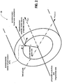
- Fig. 2 illustrates the projectile center line and the longitudinal axis about which it rotates ⁇ spin , as well as the location of an inertial sensor 40 and the lateral axis illustrating the pitch of the projectile ⁇ pitchover .
- one embodiment of the invention utilizes a Costas loop PLL as a phase detector 30 in combination with, optionally, a complementary filter 70 ( Fig. 3 ) to detect the phase of the sinusoidal rate/acceleration signal identifying the roll angle based on the inertial sensor 40 (gyro or accelerometer) information.
- a complementary filter 70 Fig. 3
- phase detector 30 utilizes a correlator 80 ( Fig. 5 ) as the phase detector 30 in combination with, optionally, a complementary filter 70 to detect the phase of the sinusoidal rate/acceleration signal identifying the roll angle based on inertial sensor 40; the choice between using pitch gyro information versus accelerometer information for the inertial sensor 40 is dependent on the application itself.
- the phase detector 30 estimates the phase error or equivalently the roll angle correction of the sinusoidal measurement signal 32 obtained from the inertial sensor 40.
- a complementary filter 70 using the roll rate from the roll gyro 50 may be inserted after the phase detector 30.
- the complementary filter 70 may also provide a coarse estimation of the roll gyro's 50 scale factor error.
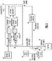
- the PLL 30 is designed as a Costas loop.
- the known Costas loop is preferred over simpler formulations of a PLL due to the inherent amplitude normalization when the in-phase and out-of-phase signals are compared in the arctan function block.
- the inertial sensor(s) 40 generates a sinusoidal measurement signal 32 in response to rotation by the projectile.
- a roll gyro 50 combined with an accumulator 54 provides a coarse estimation of the roll angle.
- the remaining circuitry provides correction to the estimation of the roll angle.
- each branch 38, 38' are the sum of two signals, one with the frequency equal to the sum of the measurement and the accumulated roll angle, and one with the difference.
- the sum frequencies do not contribute to the detection of the measurement signal's phase, so they are attenuated in low-pass filters 40, 40', one in each branch.
- the phase error between the measurement 32 and the estimated accumulated roll angle 34 may be computed by a four quadrant arctan function 33.
- the detected roll angle error correction 44 may be fed back to adjust the accumulated roll angle, using feedback control 46 that produces the roll angle correction value 48. This permits control of the estimated roll angle 58 so that the error estimated by the arctan computation results in a zero phase error between the measurement 32 and the estimated roll angle 58.
- an alternative method to estimate the roll angle is to use a correlator 80 instead of a PLL.
- the principle is to correlate the sinusoidal measurement signal 32 from the inertial sensors 40 carrying the roll angle phase information ( Fig. 6A ) with a sinewave of known phase and adjust the known phase until the sine waves' phase coincide. The phase and thus the roll angle is then known.
- correlator 80 Using just one correlator 80 will not tell the controller for the phase adjustment of the known sinewave in which direction to apply control.
- the controller principles are then to drive the two correlator 80 outputs until they lie symmetrical around the midpoint of the correlator window, indicating that the measurement signal's phase coincides with the phase of the estimated roll angle ( Figs 6C, D ).
- the total estimated roll angle 58 is made up from the accumulation of the roll gyro 50 output, representing the raw continuously increasing roll angle 52 and the corrections generated by the correlator control loop 40.
- a segment or measurement window of the sinusoidal signal ( Fig. 6A ) is correlated with two phase shifted segments of a test sine-wave signal 39, 39' with a known phase ( Fig. 6B ).
- the phase shift of the two segments is symmetric, i.e., + and - 90 degrees.
- the segments of the sensor signal 32 and the test signals 39, 39' must contain enough samples to describe at least one rotation.
- the cross-correlation returns two sequences ( Figs. 6C, D ) of length 2*N-1, where N is the number of samples in the measurement window.
- This sample error is then converted into a phase error 44 and fed back through a feed back control 46 to produce a phase correction 48 and to drive the phase error of the test signal to zero which means to drive the two correlator 80 outputs until they lie symmetrical around the midpoint of the correlator window.
- a projectile's motion is greatly influenced by aerodynamic forces. These forces create torques that make the spinning projectile precess and nutate.
- the precession and nutation motion is picked up by the pitch and yaw gyros and also in the Coriolis acceleration experienced by the longitudinal accelerometer. The result is that the phase angle determination by the PLL 30 and the correlator 80 will have the precession/nutation overlaid on the roll angle determination as a sine wave of several degrees amplitude.
- a complementary filter 70 maybe inserted after the PLL 30 ( Fig. 4 ) or the correlator 80 ( Fig. 5 ).
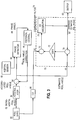
- Fig. 3 illustrates the use of a complementary filter 70.
- the version of complementary filter 70 used in embodiments of the invention blends the estimated roll angle 58 from the PLL 30 with the roll rate 52 from the roll gyro 50.
- the roll rate gyro signal 52 has better short-term behavior than the estimated roll angle 58 and is also less affected by the precession/nutation.
- the primary filtering function is performed by the integrator 74 that inputs the combined roll rate gyro signal 52 and the output of a transfer function H(s) 72.
- the transition between relying on the short term roll rate behavior and the long term roll angle behavior is determined by the parameters of the transfer function H(s) 72, which (in most cases) is a fixed gain.
- the invention shows that it is possible to estimate roll angle and other navigation states with enough accuracy to perform a coarse alignment using the methods described above. Two methods to measure roll angle information, using either gyros or accelerometers have been described.
- the present invention may be described in terms of functional block components and various processing steps. Such functional blocks may be realized by any number of hardware and/or software components configured to perform the specified functions.
- the present invention may employ various integrated circuit components, e.g., memory elements, processing elements, logic elements, look-up tables, and the like, which may carry out a variety of functions under the control of one or more microprocessors or other control devices.
- the elements of the present invention are implemented using software programming or software elements the invention may be implemented with any programming or scripting language such as C, C++, Java, assembler, or the like, with the various algorithms being implemented with any combination of data structures, objects, processes, routines or other programming elements.
- the present invention could employ any number of conventional techniques for electronics configuration, signal processing and/or control, data processing and the like.
Landscapes
- Engineering & Computer Science (AREA)
- Chemical & Material Sciences (AREA)
- Combustion & Propulsion (AREA)
- General Engineering & Computer Science (AREA)
- Gyroscopes (AREA)
- Aiming, Guidance, Guns With A Light Source, Armor, Camouflage, And Targets (AREA)
Description
- The invention relates to the field of gun-launched guidance systems and to a navigation system based on inertial sensors mounted in a spinning projectile using at least one rotation sensing device with input components perpendicular to the spinning body's longitudinal axis, or at least one acceleration sensing device with input components along the spinning body's longitudinal axis.
- A projectile in flight follows a trajectory defined by an interaction of gravity, aerodynamics, and mechanical forces due to spin, shape and possible steering fins. The projectile's flight phases can be described in terms of a pre-launch phase, launch phase, and ballistic phase.
- In the pre-launch phase, before launch of the projectile (e.g., an artillery shell), enough navigation information is available to perform a pre-launch alignment of the on-board inertial navigation system. The launch phase is characterized by high-G forces that occur during launch. During the launch phase, most navigation systems will not be able to navigate due to these high-G forces, and it is necessary to perform a post-launch alignment of the inertial system, as described below.
- After the launch phase, i.e., at the start of the ballistic phase, the navigation system has to be aligned before it can navigate. At launch, parameters such as elevation angle, muzzle velocity, heading and spin rate are known to an extent needed for a coarse alignment of the navigation system. The roll angle (the angle about the projectile's longitudinal axis, or axis roughly in parallel with its direction of travel) of the projectile is however not known. Due to the projectile's spin, the roll angle is also rapidly changing. The roll angle must therefore be established to a degree that the coarse alignment accuracy provides a sufficient initialization for a successful subsequent fine alignment phase. This process of estimating the roll angle in a spinning projectile is referred to as 'Upfinding'.
- During the ballistic phase of the trajectory, the pitch angle of the shell will decrease at a small angular rate. When the shell spins, the pitch rate can be observed in an axis perpendicular to the spin axis as a sinusoidal rate, where the maximum and minimums occur when that axis is in the horizontal plane, see
Figure 1 . The phase of the sinusoidal rate in an axis perpendicular to the projectile's spin axis can therefore be used to indicate the shell's roll angle. An accelerometer with its input axis co-aligned with the shell's spin axis and mounted off center in the shell will pick up a sinusoidal Coriolis acceleration due to the interaction of its velocity vector around the shell's center and the change in the shell's pitch rate. The phase of the sinusoidal Coriolis acceleration can also be used to indicate the shell's roll angle. - Inertial sensors that are used to determine positional and orientation parameters, including the time derivatives of these parameters, generally exceed their operational ranges during the high-g shock at launch.
- In an existing solution to the upfinding problem, a pitch- (or yaw- angle gyroscope is positioned in the shell to detect rotation in an axis perpendicular to the spin axis. The pitch-angle gyroscope detects the change in the shell's pitch angle as the shell travels in a ballistic trajectory. As the shell spins around its longitudinal axis, the gyroscope in the perpendicular axis picks up the shell's pitch rate as a sine wave. The phase of this sine wave is directly related to the shell's roll angle and can be used to estimate the roll angle. In particular, as the input axis of the gyroscope points upward or downward, the detected rotation is approximately zero; when the axis of the gyroscope is horizontal, the gyroscope senses maximum positive or negative pitch rate.
- Alternately, an accelerometer with its input axis along the shell's longitudinal axis can use the Coriolis acceleration to estimate the shell's roll angle. The measured Coriolis acceleration will also exhibit a sine wave related to the shell's roll angle.
- The existing solutions to the upfinding problem are described, e.g., in Lucia, D.J., "Estimation of the Local Vertical State for a Guided Munition Shell with an Embedded GPS/Micro-Mechanical Inertial Navigation System", MIT Masters of Science Thesis, May 1995 ("Lucia"), and Gustafson, D.E., Lucia, D.J. "Autonomous Local Vertical Determination for Guided Artillery Shells", Autonomous Local Vertical Determination for Guided Artillery Shells, D. Gustafson, Draper Laboratory; D. Lucia, Falcon AFB, pp213-221 52nd Annual Meeting Proceedings "Navigational Technology for the Third Millennium" June 19-21, 1996, Royal Sonesta Hotel, Cambridge, Massachusetts ("Gustafson & Lucia").
-
U.S. Patent No. 5,886,257 describes an apparatus and a method for making an autonomous local vertical determination for a ballistic body using recursive Kalman filtering to determine the roll angle (local vertical direction). -
U.S. Patent No. 5,372,334 describes the use of a retroreflector mounted on the projectile to implement an improved local vertical reference determination. -
U.S. Patent No. 6,163,021 describes a navigation system for spinning projectiles utilizing a magnetic spin sensor and a GPS/INS Kalman filter. - An article by Bar-Itzack, I.Y., Reiner, J. and Naroditsky, M., titled "New Inertial Azimuth Finder Apparatus", AIAA Journal of Guidance, Control and Dynamics, Vol. 24, cites Israeli Patent
129654, filed April 28, 1999 - While these references disclose various ways of finding a solution to the upfinding problem, none of them disclose an optimized system utilizing a phase-locked-loop (PLL) or a correlator or the enhancement from complementary filtering the roll angle with roll rate.
- The present invention is defined by the appended claims.
- The objective of the invention is to provide a solution to the upfinding problem in spinning projectiles by using a PLL or correlator mechanism that can be enhanced with a complementary filter. The new upfinding solutions according to the invention are simple and work in a general environment by using either accelerometers or gyros in the upfinding process under appropriate conditions.
- The phase of the sinusoidal signal from an inertial sensor as detected by a phase-locked loop or a correlator is used to determine the local vertical orientation. This invention may be used to align the inertial navigation system in spinning projectiles in ballistic trajectories, which can include, among other things, artillery shells, satellites and underwater torpedoes.
- A navigation system may be mounted in a spinning body using at least one angular sensing device measuring an angular rate perpendicular to the body's spin axis or Coriolis acceleration off-center along the body's spin axis. The measurements from the inertial sensing device exhibit a sine-wave pattern, where the sine wave's phase angle is in synchronization with the spinning body's roll angle, which relates to the local vertical. A PLL or correlator may then be used to track the phase of the sinusoidal wave.
- The invention is explained in greater detail below and references the following drawings.
- Fig. 1A
- is a pictorial diagram of a projectile illustrating rotational aspects;
- Fig. 1B
- is a diagram illustrating the various rotational axes in a three-dimensional system;
- Fig. 2
- is a pictorial diagram illustrating motion components of the accelerometer located on the projectile;
- Fig. 3
- is a block diagram illustrating the overall architecture of an upfinding system including the use of a complementary filter;
- Fig. 4
- is a block diagram showing the inputs, outputs, and feedback mechanisms for the PLL circuit and illustrating one implementation of a phase detector;
- Fig. 5
- is a block diagram for the circuit of
Fig. 4 utilizing a correlator instead of a PLL as a roll angle detector; and - Figs. 6A-D
- are graphs showing the correlation of measurement signals.
- Various preferred embodiments of the invention are described below for solving the upfinding problem using inertial sensors. As background,
Fig. 1A illustrates aprojectile 10 that has been launched on a ballistic trajectory and has some degree of rotation in the three axes (pitch, roll and yaw) illustrated inFig. 1B . -
Fig. 2 illustrates the projectile center line and the longitudinal axis about which it rotates ωspin, as well as the location of aninertial sensor 40 and the lateral axis illustrating the pitch of the projectile ωpitchover. - As shown in
Fig. 4 , one embodiment of the invention utilizes a Costas loop PLL as aphase detector 30 in combination with, optionally, a complementary filter 70 (Fig. 3 ) to detect the phase of the sinusoidal rate/acceleration signal identifying the roll angle based on the inertial sensor 40 (gyro or accelerometer) information. - Another embodiment of the invention utilizes a correlator 80 (
Fig. 5 ) as thephase detector 30 in combination with, optionally, acomplementary filter 70 to detect the phase of the sinusoidal rate/acceleration signal identifying the roll angle based oninertial sensor 40; the choice between using pitch gyro information versus accelerometer information for theinertial sensor 40 is dependent on the application itself. Thephase detector 30 estimates the phase error or equivalently the roll angle correction of thesinusoidal measurement signal 32 obtained from theinertial sensor 40. - As described below, all methods to detect the roll angle directly from the sinusoidal measurement signal show a significant sine-wave component coming from the projectile's nutation motion. To dampen the error from the nutation and to smoothen the result, a
complementary filter 70 using the roll rate from theroll gyro 50 may be inserted after thephase detector 30. Thecomplementary filter 70 may also provide a coarse estimation of the roll gyro's 50 scale factor error. - Referring to
Fig. 4 , in an embodiment of the invention, thePLL 30 is designed as a Costas loop. For detecting the phase of the small amplitude, noisy sine wave (such as that coming from the inertial sensor 40), the known Costas loop is preferred over simpler formulations of a PLL due to the inherent amplitude normalization when the in-phase and out-of-phase signals are compared in the arctan function block. - The inertial sensor(s) 40 generates a
sinusoidal measurement signal 32 in response to rotation by the projectile. Aroll gyro 50 combined with anaccumulator 54 provides a coarse estimation of the roll angle. The remaining circuitry provides correction to the estimation of the roll angle. - After the
sinusoidal measurement signal 32 is multiplied 37, 37' with thesine 36 and cosine 36' of the estimatedroll angle 34, the resulting signals in eachbranch 38, 38' are the sum of two signals, one with the frequency equal to the sum of the measurement and the accumulated roll angle, and one with the difference. The sum frequencies do not contribute to the detection of the measurement signal's phase, so they are attenuated in low-pass filters 40, 40', one in each branch. - The phase error between the
measurement 32 and the estimated accumulatedroll angle 34 may be computed by a four quadrant arctan function 33. To make the loop lock on to themeasurement signal 32, the detected rollangle error correction 44 may be fed back to adjust the accumulated roll angle, usingfeedback control 46 that produces the rollangle correction value 48. This permits control of the estimatedroll angle 58 so that the error estimated by the arctan computation results in a zero phase error between themeasurement 32 and the estimatedroll angle 58. - Referring to
Figs. 5 and6A-D , an alternative method to estimate the roll angle is to use acorrelator 80 instead of a PLL. The principle is to correlate thesinusoidal measurement signal 32 from theinertial sensors 40 carrying the roll angle phase information (Fig. 6A ) with a sinewave of known phase and adjust the known phase until the sine waves' phase coincide. The phase and thus the roll angle is then known. - Using just one
correlator 80 will not tell the controller for the phase adjustment of the known sinewave in which direction to apply control. A scheme of twocorrelators 80 fed withsinewaves 39, 39' that lead and lag the known phase with an equal amount is the solution used in this embodiment (Fig. 6B ). The controller principles are then to drive the twocorrelator 80 outputs until they lie symmetrical around the midpoint of the correlator window, indicating that the measurement signal's phase coincides with the phase of the estimated roll angle (Figs 6C, D ). - The total estimated
roll angle 58 is made up from the accumulation of theroll gyro 50 output, representing the raw continuously increasingroll angle 52 and the corrections generated by thecorrelator control loop 40. - A segment or measurement window of the sinusoidal signal (
Fig. 6A ) is correlated with two phase shifted segments of a test sine-wave signal 39, 39' with a known phase (Fig. 6B ). The phase shift of the two segments is symmetric, i.e., + and - 90 degrees. The segments of thesensor signal 32 and the test signals 39, 39' must contain enough samples to describe at least one rotation. The cross-correlation returns two sequences (Figs. 6C, D ) oflength 2*N-1, where N is the number of samples in the measurement window. - An error is calculated from the maximums of the two phase shifted correlation signals and the symmetry point of the measurement window, such that the Error = (d1 - d2)/2) where:
- d1
- represents the number of samples that the +90 deg shifted test signal deviates from the symmetry point N at which the maximum should occur if the measurement signal's phase coincides with the phase of the estimated roll angle (
Fig. 6C ); and - d2
- represents the number of samples that the -90 deg shifted test signal deviates from the symmetry point N at which the maximum should occur if the measurement signal's phase coincides with the phase of the estimated roll angle (
Fig. 6D ). - This sample error is then converted into a
phase error 44 and fed back through a feed backcontrol 46 to produce aphase correction 48 and to drive the phase error of the test signal to zero which means to drive the twocorrelator 80 outputs until they lie symmetrical around the midpoint of the correlator window. - A projectile's motion is greatly influenced by aerodynamic forces. These forces create torques that make the spinning projectile precess and nutate. The precession and nutation motion is picked up by the pitch and yaw gyros and also in the Coriolis acceleration experienced by the longitudinal accelerometer. The result is that the phase angle determination by the
PLL 30 and thecorrelator 80 will have the precession/nutation overlaid on the roll angle determination as a sine wave of several degrees amplitude. - To dampen the effect of the precession/nutation and also smoothen the estimation of the accumulated roll angle, a
complementary filter 70 maybe inserted after the PLL 30 (Fig. 4 ) or the correlator 80 (Fig. 5 ).Fig. 3 illustrates the use of acomplementary filter 70. The version ofcomplementary filter 70 used in embodiments of the invention blends the estimatedroll angle 58 from thePLL 30 with theroll rate 52 from theroll gyro 50. The rollrate gyro signal 52 has better short-term behavior than the estimatedroll angle 58 and is also less affected by the precession/nutation. The primary filtering function is performed by theintegrator 74 that inputs the combined rollrate gyro signal 52 and the output of a transfer function H(s) 72. The transition between relying on the short term roll rate behavior and the long term roll angle behavior is determined by the parameters of the transfer function H(s) 72, which (in most cases) is a fixed gain. - By comparing the
roll rate 52 from theroll gyro 50 with the complementary filtered roll rate, it is also possible to estimate the roll gyro scale factor error. - The invention shows that it is possible to estimate roll angle and other navigation states with enough accuracy to perform a coarse alignment using the methods described above. Two methods to measure roll angle information, using either gyros or accelerometers have been described.
- For the purposes of promoting an understanding of the principles of the invention, reference has been made to the preferred embodiments illustrated in the drawings, and specific language has been used to describe these embodiments. However, no limitation of the scope of the invention is intended by this specific language, and the invention should be construed to encompass all embodiments that would normally occur to one of ordinary skill in the art.
- The present invention may be described in terms of functional block components and various processing steps. Such functional blocks may be realized by any number of hardware and/or software components configured to perform the specified functions. For example, the present invention may employ various integrated circuit components, e.g., memory elements, processing elements, logic elements, look-up tables, and the like, which may carry out a variety of functions under the control of one or more microprocessors or other control devices. Similarly, where the elements of the present invention are implemented using software programming or software elements the invention may be implemented with any programming or scripting language such as C, C++, Java, assembler, or the like, with the various algorithms being implemented with any combination of data structures, objects, processes, routines or other programming elements. Furthermore, the present invention could employ any number of conventional techniques for electronics configuration, signal processing and/or control, data processing and the like.
- The particular implementations shown and described herein are illustrative examples of the invention and are not intended to otherwise limit the scope of the invention in any way. For the sake of brevity, conventional electronics, control systems, software development and other functional aspects of the systems (and components of the individual operating components of the systems) may not be described in detail. Furthermore, the connecting lines, or connectors shown in the various figures presented are intended to represent exemplary functional relationships
and/or physical or logical couplings between the various elements. It should be noted that many alternative or additional functional relationships, physical connections or logical connections may be present in a practical device. Moreover, no item or component is essential to the practice of the invention unless the element is specifically described as "essential" or "critical". -
- 10
- projectile
- 30
- phase-locked loop (PLL); phase detector
- 32
- inertial sensor signal; sinusoidal measurement signal
- 33
- four-quadrant arctan function
- 34
- estimated roll angle
- 35, 35'
- low pass filter
- 36
- sine function cosine
- 36'
- function multiplier
- 37, 37'
- multiplied signals
- 38, 38'
- sinewaves
- 39, 39'
- inertial sensor; rotation sensing device (e.g., accelerometer, pitch/yaw gyro) phase
- 40
- error
- 44
- feedback loop control
- 46
- correlator control loop phase correction
- 48
- Incremental roll angle
- 52
- accumulator for roll incremental angle adder
- 54
- estimated roll angle
- 56
- output complementary
- 58, 58'
- filter
- 72
- filter transfer function
- 80, 80'
- correlator; phase detector; correlator components distance from longitudinal axis to rotation sensing device
Claims (10)
- An apparatus for upfinding in a spinning projectile (10) rotating about its longitudinal axis, comprising:an inertial sensor (40) comprising a signal output that outputs a rotation signal (32) related to the rate of rotation about the longitudinal axis;a roll gyro (50) having an output;an accumulator (54) having an input, coupled to the output of the roll gyro (50), and an output; wherein an estimated roll angle (58) is configured to be generated by adding an output of a feedback path (46) with the output of the accumulator (54);a phase detector (30, 80) comprising a first input coupled to the signal output of the inertial sensor (40), a second input coupled to the estimated roll angle (58), and an output (44) coupled to the feedback path (46), at which a phase error between the signal output of the inertial sensor (40) and the estimated roll angle (58) is provided;wherein the phase detector (30, 80) is configured to reduce the phase error (44) to zero via the feedback path (46); andan output (60) connected to the output of the phase detector (30, 80) at which the estimated roll angle (58) is provided.
- The apparatus according to claim 1, wherein the phase detector (30, 80) comprises a phase-locked loop, PLL, (30).
- The apparatus according to claim 2, wherein the PLL (30) comprises a Costas loop.
- The apparatus according to claim 1, wherein the phase detector (30, 80) comprises a correlator (80).
- The apparatus according to claim 4, wherein the phase detector (80) comprises two phase detector components, each comprising:an input for a test signal (39, 39') derived from the estimated roll angle (58)an input for the rotation signal; anda driving mechanism configured to drive a correlator output until it lies symmetrical around a midpoint of a correlator window indicating that a phase of the rotation signal (32) coincides with a phase of the estimated roll angle (58).
- The apparatus according to claim 1, further comprising:a complementary filter (70) comprisingan input at which the estimated roll angle (58) is provided,an input at which an incremental roll angle (52) is provided from the roll gyro (50), andan output (60) at which an enhanced estimated roll angle (58') is provided.
- The apparatus according to claim 6, wherein the complementary filter (70) further comprises:a transfer function component (72) having an input coupled to the estimated roll angle (58) and an enhanced estimated roll angle (58'); andan integrator (74) coupled to the incremental roll angle (52) and an output of the transfer function component (72).
- The apparatus according to claim 7, wherein the transfer function component (72) is at a minimum a gain function.
- The apparatus according to claim 1, wherein the inertial sensor (40) is an accelerometer mounted away from a longitudinal axis of the projectile and with its input axis in the direction of the longitudinal axis.
- The apparatus according to claim 1, wherein the inertial sensor (40) is a gyroscope with the input axis perpendicular to the longitudinal axis of the projectile
Applications Claiming Priority (2)
| Application Number | Priority Date | Filing Date | Title |
|---|---|---|---|
| US11/189,905 US7395987B2 (en) | 2005-07-26 | 2005-07-26 | Apparatus and appertaining method for upfinding in spinning projectiles using a phase-lock-loop or correlator mechanism |
| PCT/US2006/028525 WO2007015996A2 (en) | 2005-07-26 | 2006-07-24 | Apparatus and appertaining method for upfinding in spinning projectiles using a phase-lock-loop or correlator mechanism |
Publications (2)
| Publication Number | Publication Date |
|---|---|
| EP1910770A2 EP1910770A2 (en) | 2008-04-16 |
| EP1910770B1 true EP1910770B1 (en) | 2018-01-03 |
Family
ID=37693248
Family Applications (1)
| Application Number | Title | Priority Date | Filing Date |
|---|---|---|---|
| EP06800234.4A Ceased EP1910770B1 (en) | 2005-07-26 | 2006-07-24 | Apparatus and appertaining method for upfinding in spinning projectiles using a phase-lock-loop or correlator mechanism |
Country Status (4)
| Country | Link |
|---|---|
| US (1) | US7395987B2 (en) |
| EP (1) | EP1910770B1 (en) |
| IL (1) | IL189012A (en) |
| WO (1) | WO2007015996A2 (en) |
Families Citing this family (21)
| Publication number | Priority date | Publication date | Assignee | Title |
|---|---|---|---|---|
| US8413931B2 (en) * | 2006-09-13 | 2013-04-09 | Honeywell International Inc. | System and method for reducing attitude errors for exoatmospheric devices |
| DE102009007668B4 (en) * | 2009-02-05 | 2015-10-15 | Diehl Bgt Defence Gmbh & Co. Kg | Steering module for a ballistic projectile |
| US8119958B2 (en) | 2009-02-19 | 2012-02-21 | Lockheed Martin Corporation | Method and device for matrix of explosive cells |
| US8198572B1 (en) | 2009-06-03 | 2012-06-12 | Raytheon Company | Self clocking for distributed projectile guidance |
| JP2011019035A (en) * | 2009-07-08 | 2011-01-27 | Ricoh Co Ltd | Information device, imaging apparatus having the same, and method of angle correction |
| US8047070B2 (en) * | 2009-09-16 | 2011-11-01 | Raytheon Company | Fast response projectile roll estimator |
| US8779971B2 (en) | 2010-05-24 | 2014-07-15 | Robert J. Wellington | Determining spatial orientation information of a body from multiple electromagnetic signals |
| US9645251B1 (en) * | 2014-03-26 | 2017-05-09 | Exelis Inc. | Estimation of roll and roll rate of a spinning body based on a signal received from a remote transmitter |
| GB2565264B (en) * | 2017-05-23 | 2022-03-09 | Atlantic Inertial Systems Ltd | Inertial navigation system |
| WO2019010260A1 (en) * | 2017-07-05 | 2019-01-10 | The Charles Stark Draper Laboratory, Inc. | Virtual roll gyro for spin-stabilized projectiles |
| US11078762B2 (en) | 2019-03-05 | 2021-08-03 | Swm International, Llc | Downhole perforating gun tube and components |
| US12291945B1 (en) | 2019-03-05 | 2025-05-06 | Swm International, Llc | Downhole perforating gun system |
| US10689955B1 (en) | 2019-03-05 | 2020-06-23 | SWM International Inc. | Intelligent downhole perforating gun tube and components |
| US11268376B1 (en) | 2019-03-27 | 2022-03-08 | Acuity Technical Designs, LLC | Downhole safety switch and communication protocol |
| US10907936B2 (en) * | 2019-05-17 | 2021-02-02 | Bae Systems Information And Electronic Systems Integration Inc. | State estimation |
| US11619119B1 (en) | 2020-04-10 | 2023-04-04 | Integrated Solutions, Inc. | Downhole gun tube extension |
| US11790793B2 (en) * | 2021-01-08 | 2023-10-17 | Honeywell International Inc. | Systems and methods for model based vehicle navigation |
| US12152862B2 (en) * | 2021-02-18 | 2024-11-26 | Honeywell International Inc. | Tightly coupled trajectory predictor with constant up-finding |
| US11781836B2 (en) | 2021-03-04 | 2023-10-10 | Honeywell International Inc. | Systems and methods for model based inertial navigation for a spinning projectile |
| CN114970013B (en) * | 2022-05-12 | 2023-08-15 | 北京自动化控制设备研究所 | A Method for Initial Alignment of Rotating Projectiles |
| CN116500645A (en) * | 2023-04-28 | 2023-07-28 | 中国国家铁路集团有限公司 | Vehicle-mounted laser point cloud invasion recognition method and device |
Family Cites Families (27)
| Publication number | Priority date | Publication date | Assignee | Title |
|---|---|---|---|---|
| US3844506A (en) * | 1961-02-06 | 1974-10-29 | Singer Co | Missile guidance system |
| DE977989C (en) * | 1964-06-19 | 1974-12-12 | ||
| US3527429A (en) * | 1968-03-15 | 1970-09-08 | Gen Dynamics Corp | Body motion decoupler |
| US4264907A (en) * | 1968-04-17 | 1981-04-28 | General Dynamics Corporation, Pomona Division | Rolling dual mode missile |
| US3897918A (en) * | 1974-02-27 | 1975-08-05 | Us Navy | Interferometric rolling missile body decoupling guidance system |
| US5835056A (en) * | 1975-10-31 | 1998-11-10 | The Secretary Of State For Defence In Her Britannic Majesty's Government Of The United Kingdom Of Great Britain And Northern Ireland | Apparatus for directing a mobile craft to a rendevous with another mobile craft |
| US5805102A (en) * | 1975-10-31 | 1998-09-08 | The Secretary Of State For Defence In Her Britannic Majesty's Government Of The United Kingdom Of Great Britain And Northern Ireland | Apparatus for directing a mobile craft to a rendevous with another mobile craft |
| US4848158A (en) * | 1983-03-31 | 1989-07-18 | Honeywell Inc. | Single-axis centrifugal rate sensor |
| DE3529277A1 (en) | 1985-08-16 | 1987-03-05 | Messerschmitt Boelkow Blohm | Control method for missiles |
| US4646990A (en) * | 1986-02-18 | 1987-03-03 | Ford Aerospace & Communications Corporation | Magnetic roll sensor calibrator |
| US4791573A (en) * | 1986-09-02 | 1988-12-13 | Sanders Associates, Inc. | State-deviation-estimation circuit employing a phase-locked-loop phase reference |
| DE3832389A1 (en) | 1988-09-23 | 1990-04-05 | Telefunken Systemtechnik | Sensor device for guiding the end phase of bodies of munitions |
| US5072890A (en) * | 1989-08-18 | 1991-12-17 | Raytheon Company | Optical system |
| US4973013A (en) * | 1989-08-18 | 1990-11-27 | Raytheon Company | Seeker |
| US5127604A (en) * | 1989-08-18 | 1992-07-07 | Raytheon Company | Optical system |
| US5114094A (en) * | 1990-10-23 | 1992-05-19 | Alliant Techsystems, Inc. | Navigation method for spinning body and projectile using same |
| SE468726B (en) * | 1991-07-02 | 1993-03-08 | Bofors Ab | DEVICE FOR ROLL ANGLE DETERMINATION |
| US5372334A (en) | 1993-04-23 | 1994-12-13 | Hughes Missile Systems Company | Local vertical sensor for externally-guided projectiles |
| US5593109A (en) * | 1995-01-10 | 1997-01-14 | Lucas Western, Inc. | Actuator system and method |
| US5886257A (en) | 1996-07-03 | 1999-03-23 | The Charles Stark Draper Laboratory, Inc. | Autonomous local vertical determination apparatus and methods for a ballistic body |
| US6450442B1 (en) * | 1997-09-30 | 2002-09-17 | Raytheon Company | Impulse radar guidance apparatus and method for use with guided projectiles |
| US6016990A (en) * | 1998-04-09 | 2000-01-25 | Raytheon Company | All-weather roll angle measurement for projectiles |
| SE513028C2 (en) * | 1998-10-29 | 2000-06-19 | Bofors Missiles Ab | Method and apparatus for determining roll angle |
| US6163021A (en) * | 1998-12-15 | 2000-12-19 | Rockwell Collins, Inc. | Navigation system for spinning projectiles |
| IL129654A (en) | 1999-04-28 | 2003-10-31 | Rafael Armament Dev Authority | Method and apparatus for determining the geographical heading of a body |
| US6596976B2 (en) * | 1999-12-07 | 2003-07-22 | American Gnc Corporation | Method and system for pointing and stabilizing a device |
| FR2847033B1 (en) * | 2002-11-08 | 2004-12-17 | Giat Ind Sa | METHOD FOR THE PREPARATION OF A CONTROL ORDER FOR A MEMBER ALLOWING THE PILOTAGE OF A GIRANT PROJECTILE |
-
2005
- 2005-07-26 US US11/189,905 patent/US7395987B2/en not_active Expired - Fee Related
-
2006
- 2006-07-24 EP EP06800234.4A patent/EP1910770B1/en not_active Ceased
- 2006-07-24 WO PCT/US2006/028525 patent/WO2007015996A2/en not_active Ceased
-
2008
- 2008-01-24 IL IL189012A patent/IL189012A/en not_active IP Right Cessation
Also Published As
| Publication number | Publication date |
|---|---|
| WO2007015996A3 (en) | 2007-05-31 |
| IL189012A (en) | 2011-11-30 |
| US7395987B2 (en) | 2008-07-08 |
| US20070023567A1 (en) | 2007-02-01 |
| IL189012A0 (en) | 2008-08-07 |
| WO2007015996A2 (en) | 2007-02-08 |
| EP1910770A2 (en) | 2008-04-16 |
Similar Documents
| Publication | Publication Date | Title |
|---|---|---|
| IL189012A (en) | Apparatus and method for upfinding in spinning projectiles using a phase-lock-loop or correlator mechanism | |
| US6163021A (en) | Navigation system for spinning projectiles | |
| EP2583059B1 (en) | Improved north finder | |
| US6779752B1 (en) | Projectile guidance with accelerometers and a GPS receiver | |
| US6573486B1 (en) | Projectile guidance with accelerometers and a GPS receiver | |
| EP1718918B1 (en) | Rf attitude measurement system and method | |
| EP3213034B1 (en) | Inertial navigation system with compensation of roll scale factor error | |
| US6345785B1 (en) | Drag-brake deployment method and apparatus for range error correction of spinning, gun-launched artillery projectiles | |
| US20030105588A1 (en) | Method and wystem for pointing and stabilizing a device | |
| EP3189303B1 (en) | Pedestrian navigation devices and methods | |
| Stančić et al. | The integration of strap-down INS and GPS based on adaptive error damping | |
| Avrutov et al. | Gyrocompassing mode of the attitude and heading reference system | |
| US9207328B2 (en) | System and method for determination of attitude for projectile | |
| EP2758741A1 (en) | Method and gnc system for determination of roll angle | |
| EP1048929A2 (en) | Method and apparatus for determining the geographic heading of a body | |
| CN109752749B (en) | Attitude estimation method and system for low-spin components of a high-spin aircraft | |
| Kreichauf et al. | Estimation of the roll angle in a spinning guided munition shell | |
| CN116070066B (en) | Method for calculating rolling angle of guided projectile | |
| US11913757B2 (en) | Constraining navigational drift in a munition | |
| RU2308004C1 (en) | Method for orientation of polar electrostatic gyroscope of ship-based navigation system | |
| Xiangming et al. | Gyrocompassing mode of the strapdown inertial navigation system | |
| CN116878502A (en) | Guided projectile roll angle identification method based on double accelerometers and roll gyroscopes | |
| CA3189127C (en) | Absolute heading estimation with constrained motion | |
| Erdemir et al. | Real time roll angle estimation for fast spinning projectiles | |
| Ata et al. | Enhanced Inertial Navigation System for Missile Applications Using Seeker, RF Data Link and Radar Altimeter Measurements |
Legal Events
| Date | Code | Title | Description |
|---|---|---|---|
| PUAI | Public reference made under article 153(3) epc to a published international application that has entered the european phase |
Free format text: ORIGINAL CODE: 0009012 |
|
| 17P | Request for examination filed |
Effective date: 20080123 |
|
| AK | Designated contracting states |
Kind code of ref document: A2 Designated state(s): DE FR GB |
|
| DAX | Request for extension of the european patent (deleted) | ||
| RIN1 | Information on inventor provided before grant (corrected) |
Inventor name: KREICHAUF, RUTHC Inventor name: LINDQUIST, ERIK |
|
| RBV | Designated contracting states (corrected) |
Designated state(s): DE FR GB |
|
| RAP1 | Party data changed (applicant data changed or rights of an application transferred) |
Owner name: HONEYWELL INTERNATIONAL INC. |
|
| 17Q | First examination report despatched |
Effective date: 20161223 |
|
| GRAP | Despatch of communication of intention to grant a patent |
Free format text: ORIGINAL CODE: EPIDOSNIGR1 |
|
| INTG | Intention to grant announced |
Effective date: 20170822 |
|
| GRAS | Grant fee paid |
Free format text: ORIGINAL CODE: EPIDOSNIGR3 |
|
| GRAA | (expected) grant |
Free format text: ORIGINAL CODE: 0009210 |
|
| AK | Designated contracting states |
Kind code of ref document: B1 Designated state(s): DE FR GB |
|
| REG | Reference to a national code |
Ref country code: GB Ref legal event code: FG4D |
|
| REG | Reference to a national code |
Ref country code: DE Ref legal event code: R096 Ref document number: 602006054479 Country of ref document: DE |
|
| REG | Reference to a national code |
Ref country code: FR Ref legal event code: PLFP Year of fee payment: 13 |
|
| REG | Reference to a national code |
Ref country code: DE Ref legal event code: R097 Ref document number: 602006054479 Country of ref document: DE |
|
| PLBE | No opposition filed within time limit |
Free format text: ORIGINAL CODE: 0009261 |
|
| STAA | Information on the status of an ep patent application or granted ep patent |
Free format text: STATUS: NO OPPOSITION FILED WITHIN TIME LIMIT |
|
| 26N | No opposition filed |
Effective date: 20181005 |
|
| REG | Reference to a national code |
Ref country code: DE Ref legal event code: R119 Ref document number: 602006054479 Country of ref document: DE |
|
| GBPC | Gb: european patent ceased through non-payment of renewal fee |
Effective date: 20180724 |
|
| PG25 | Lapsed in a contracting state [announced via postgrant information from national office to epo] |
Ref country code: GB Free format text: LAPSE BECAUSE OF NON-PAYMENT OF DUE FEES Effective date: 20180724 Ref country code: DE Free format text: LAPSE BECAUSE OF NON-PAYMENT OF DUE FEES Effective date: 20190201 |
|
| PGFP | Annual fee paid to national office [announced via postgrant information from national office to epo] |
Ref country code: FR Payment date: 20190725 Year of fee payment: 14 |
|
| PG25 | Lapsed in a contracting state [announced via postgrant information from national office to epo] |
Ref country code: FR Free format text: LAPSE BECAUSE OF NON-PAYMENT OF DUE FEES Effective date: 20200731 |
|
| P01 | Opt-out of the competence of the unified patent court (upc) registered |
Effective date: 20230525 |