EP1909413A1 - Improved bandwidth limited PSBT system - Google Patents
Improved bandwidth limited PSBT system Download PDFInfo
- Publication number
- EP1909413A1 EP1909413A1 EP06301016A EP06301016A EP1909413A1 EP 1909413 A1 EP1909413 A1 EP 1909413A1 EP 06301016 A EP06301016 A EP 06301016A EP 06301016 A EP06301016 A EP 06301016A EP 1909413 A1 EP1909413 A1 EP 1909413A1
- Authority
- EP
- European Patent Office
- Prior art keywords
- optical
- pass filter
- psbt
- signal
- bandwidth
- Prior art date
- Legal status (The legal status is an assumption and is not a legal conclusion. Google has not performed a legal analysis and makes no representation as to the accuracy of the status listed.)
- Granted
Links
- 101150083542 PSBT gene Proteins 0.000 title claims 12
- 230000003287 optical effect Effects 0.000 claims abstract description 108
- 230000005540 biological transmission Effects 0.000 claims abstract description 65
- 238000000034 method Methods 0.000 claims abstract description 13
- 238000005457 optimization Methods 0.000 claims description 9
- 230000006978 adaptation Effects 0.000 claims description 5
- 239000006185 dispersion Substances 0.000 description 14
- 230000000875 corresponding effect Effects 0.000 description 6
- 230000000295 complement effect Effects 0.000 description 3
- 238000010586 diagram Methods 0.000 description 3
- 230000001419 dependent effect Effects 0.000 description 2
- 239000000835 fiber Substances 0.000 description 2
- 230000003993 interaction Effects 0.000 description 2
- 230000009467 reduction Effects 0.000 description 2
- 230000008901 benefit Effects 0.000 description 1
- 230000015556 catabolic process Effects 0.000 description 1
- 238000006731 degradation reaction Methods 0.000 description 1
- 238000011161 development Methods 0.000 description 1
- 230000018109 developmental process Effects 0.000 description 1
- 230000009977 dual effect Effects 0.000 description 1
- 238000005516 engineering process Methods 0.000 description 1
- 238000001914 filtration Methods 0.000 description 1
- 230000007274 generation of a signal involved in cell-cell signaling Effects 0.000 description 1
- 230000006872 improvement Effects 0.000 description 1
- 238000009434 installation Methods 0.000 description 1
- 230000010354 integration Effects 0.000 description 1
- 238000011835 investigation Methods 0.000 description 1
- 230000010363 phase shift Effects 0.000 description 1
- 230000004044 response Effects 0.000 description 1
- 238000005070 sampling Methods 0.000 description 1
- 230000035945 sensitivity Effects 0.000 description 1
- 238000004088 simulation Methods 0.000 description 1
- 230000003595 spectral effect Effects 0.000 description 1
- 238000001228 spectrum Methods 0.000 description 1
Images

Classifications
-
- H—ELECTRICITY
- H04—ELECTRIC COMMUNICATION TECHNIQUE
- H04B—TRANSMISSION
- H04B10/00—Transmission systems employing electromagnetic waves other than radio-waves, e.g. infrared, visible or ultraviolet light, or employing corpuscular radiation, e.g. quantum communication
- H04B10/50—Transmitters
- H04B10/516—Details of coding or modulation
- H04B10/5167—Duo-binary; Alternative mark inversion; Phase shaped binary transmission
Definitions
- the present invention relates to a method to optimize the transmission of Duobinary or Phase Shaped Binary Transmission /PSBT/ signals over an optical transmission system. Furthermore, it is related to a transmitter for generating Duobinary or Phase Shaped Binary Transmission /PSBT/ signals. It is also related to a system for optimized transmission of Duobinary or Phase Shaped Binary Transmission /PSBT/ signals with a transmitter, an optical transmission system and a receiver.
- EDC Electronic dispersion compensation
- EDC Electronic dispersion compensation
- VE Digital Viterbi equalizers
- 20 GS/s (20*10 9 samples per second, a sample being 3 to 4 bit long
- 18 GHz bandwidth analog to digital converters with sampling rates up to 60 GS/s realized for instrumentation are close to the bandwidth requirements for Viterbi equalizers (20 GHz).
- the digital processing of data in a subrate processor requires high integration complexity delivered by state of the art CMOS technologies.
- 43 Gb/s Viterbi equalizers ought to be feasible, the efficiency of VE in real 43 GHz systems has to be investigated by in-depth simulations.
- PSBT phase shaped binary transmission
- DQPSK differential quaternary phase shift keying
- the optical bandwidth in WDM systems is determined by the width of each filter and the overall number of filters (AWG, ROADM) in the link. In more complex links especially in metro links a higher number of filter elements may be applied.
- AMG overall number of filters
- ROADM residual chromatic dispersion
- the RCDC needs any adaptation to tune it for optimum system performance. PSBT systems suffer from a non optimum performance at zero distortion. They are two settings of RCDC for optimum system performance in positive and negative dispersion region. It runs randomly in one optimum at zero dispersion. If increasing the dispersion of link to positive or negative values the tuning range is unsymmetrical and very small in one direction. Even in case of RCDC application very low dispersion tolerances may occur.
- PSBT is of very high interest for many competitors and it is planned to define PSBT systems in an ITU standard.
- Today's task is to find the optimum technical solution and to consider this solution during standardisation.
- Standard PSBT transmitters are realised with fixed settings of parameters for one application without the opportunity to adjust it to the available transmission link. Usually, they are optimised for high optical bandwidth links.
- the optimisation of PSBT by optical bandwidth limitation has been reported. Therein the interaction of transmitter and bandwidth of channel are considered, not the receiver.
- the application of Viterbi equalizers in receivers for PSBT systems has been published and a low improvement of dispersion tolerances has been found. Up to now no setup for optimisation of interacting transmitter, channel and receiver has been found.
- US 2004/0101314 A1 discloses a duobinary optical transmission apparatus with an optical band pass filter for generating a duobinary optical signal without using an electric low pass filter.
- US 6,623,188 B1 discloses an optical data transmitter comprising a differential amplifier for generating a four-level data signal and a complementary four-level data signal.
- An optical data modulator modulates an amplitude of an optical signal applied to an optical input thereof in response to at least one of the four-level data signal and the complementary four-level data signal to generate a modulated optical amplitude data signal that is bipolar and that includes four amplitude levels.
- a filter is coupled between the differential amplifier and the modulator for reducing the bandwidth of the four-level and the complementary four-level data signal.
- PSBT Phase Shaped Binary Transmission
- This object is achieved in accordance with the invention by applying a method to optimize the transmission of Duobinary or Phase Shaped Binary Transmission (PSBT) signals over an optical transmission system comprising the steps to pre-code a data stream to be transmitted over the optical transmission system while generating out of that precoded data stream a three level electrical signal using a variable electrical low pass filter. Latter electrical signal is then feed to an interferometer or push-pull modulator to generate a corresponding optical PSBT signal. Such resulting optical PSBT signal is transmitted through the optical transmission system.
- PSBT Phase Shaped Binary Transmission
- An optimization according to the invention of the transmission quality for the optical PSBT signal over the optical transmission system is reached by adapting the bandwidth of the variable electrical low pass filter with respect to the chosen bandwidth of a tuneable optical filter through which the optical PSBT signal are forwarded either at the output of the transmitter side or at the input of the receiver side.
- Such optimization is performed according to an embodiment using look up table with predefined values corresponding to an optical transmission system with known link and receiver characteristics.
- a feed back signal is used to adapt the electrical low pass filter together with the tuneable optical band pass filter. It is conceivable to use some feedback signal generation setup to control the variation of the electrical low pass filter.
- the bandwidth of the optical band pass filter is selected with respect to the bandwidth of the channel within which the optical signal are transmitted over the optical transmission network.
- Both the low pass filter and the band pass filter are adapted to a non optimum eye opening at transmission side setting the optical zero close to zero i.e. to a minimum magnitude. That minimum is then chosen for some specific binary sequence signal like e.g. 010.
- the receiver comprises a Viterbi equalizer.
- the invention further relates to a transmitter for generating Duobinary or Phase Shaped Binary Transmission (PSBT) signals which comprises a precoder for precoding a data stream to be transmitted over an optical transmission system, variable electrical low pass filter for generating a three level electrical signal out of that precoded data stream, an interferometer or push-pull modulator feed with that three level electrical signal to generate a corresponding optical PSBT signal.
- the bandwidth of the variable electrical low pass filter is adapted with respect to the chosen bandwidth of a tuneable optical filter through which the optical PSBT signal is forwarded to optimize the transmission quality over the optical transmission system.
- the tuneable optical band pass filter is at the output of the transmitter while possibly connected to some feedback path to be used for the optimization.
- the invention also relates to a system for optimized transmission of PSBT signals comprising a transmitter for generating PSBT signals with a precoder for precoding a data stream to be transmitted over an optical transmission system being part of that system, variable electrical low pass filter for generating a three level electrical signal out of that precoded data stream, an interferometer or push-pull modulator feed with that three level electrical signal to generate a corresponding optical PSBT signal and a receiver interconnected with the transmitter via the optical transmission system.
- the bandwidth of the variable electrical low pass filter is adapted with respect to the chosen bandwidth of a tuneable optical filter being part of that system and through which the optical PSBT signal is forwarded to optimize the transmission quality over the optical transmission system.
- the tuneable optical band pass filter is at the input of the receiver.
- the receiver comprises a Viterbi equalizer.
- On figure 1 is shown a transmission system consisting of a transmitter, a multiplexer, fiber links with add and drop multiplexer and a demultiplexer before the receiver.
- the optical components may act as optical filters due to their limited bandwidth.
- On figure 2 is shown a transmitter for generating optical PSBT signals as used for the present invention. It consists of a precoder, electrical low pass filters and a push-pull modulator or Mach-Zehnder interferometer (MZI).
- MZI Mach-Zehnder interferometer
- the bandwidth limited PSBT signal is generated by precoding and low pass filtering of the non-inverted and inverted precoded data streams. Latter precoded signal drive the dual drive MZI.
- the cut-off frequency of the electrical low pass filters is about 30% of bit rate frequency. After being filtered by the low pass filter, a three level signal with "-1", "0", and "1" is then available, which is necessary to generate the three level PSBT optical signal.
- the electrical low pass filters are optimised according to the present invention for the whole system.
- the optimisation is realised using variable electrical low pass filters while the variation consists on the possibility to adapt the cut off frequency of that filters by more than 20%.
- an additional tuneable optical filter can be used which cuts the spectra leading to a reduction of field components at logical "0".
- the optimisation of the filters particularly the electrical low pass filters needs the knowledge of optical channel and the receiver i.e. to know all the characteristics of the links within the optical transmission system as well as the receiver characteristic.
- the setting of the transmitter for the optimization can be performed following different possibilities.
- One possibility is to use a look up table with predefined values corresponding to an optical transmission system with well known links and receiver characteristics. It has the big advantage that no feed back signal must be collected and can be therefore quite cost effective. But it is rather sensible to any changes or instabilities within the optical transmission system.
- An alternative for the optimization can be achieved using some feedback signal.
- Such signal can be collected from the receiver via back channel or generated in the receiver.
- a control apparatus collects that feedback signal to control accordingly the cut off frequency of the electrical variable low pass filters.
- the cut off frequency can be chosen at around 3 GHz and be varied by 20% i.e. ⁇ 300 MHz till achieving maximal performance i.e. minimal bit errors.
- the feed back signal is generated at the transmitter behind the optical filter when placed on the transmitter side.
- At least one optical filter can be applied to realise a system with optical bandwidth limitation.
- the bandwidth limitation may be realised by separate filters, by optical network elements or by both.
- the setting/choice of optical filters can be performed by considering the whole channel. Dependent on application the lowest bandwidth filter is possibly placed at receiver side.
- FIG 3 is shown an example of a receiver according to the invention with a lowest electrical bandwidth filter placed after the diode acting as an optical/electrical converter. Also is placed at the input of that receiver the tuneable optical band pass filter. In some other alternatives, that tuneable optical band pass filter can be placed at the output of the transmitter or simply omitted since the corresponding properties being already obtained by the different elements within the optical transmission system.
- the receiver is assembled with an analog/digital converter ADC and a digital Viterbi equalizer.
- a residual chromatic dispersion compensation RCDC can be applied optionally.
- the optical filter is adjusted with same boundary conditions as the Tx filter. If possibly, no filter is in the Tx and lowest bandwidth filter is applied in Rx.
- the adaptation of RCDC can be performed by the Viterbi channel estimator.
- the RCDC is adjusted by a chromatic dispersion sensitive feedback or by an eye monitor.
- a further implementation considers a variable optical filter with feedback from channel estimator or eye monitor. Due to interaction of feedback signal, variable filter in Rx any suboptimum setting can be avoided.
- the electrical bandwidth in Tx is preferably 105% of the optimum bandwidth of standard Rx.
- the electrical bandwidth of Rx is set to 90% of optimum bandwidth for standard Rx.
Landscapes
- Physics & Mathematics (AREA)
- Electromagnetism (AREA)
- Engineering & Computer Science (AREA)
- Computer Networks & Wireless Communication (AREA)
- Signal Processing (AREA)
- Optical Communication System (AREA)
- Amplifiers (AREA)
- Dc Digital Transmission (AREA)
Abstract
Description
- The present invention relates to a method to optimize the transmission of Duobinary or Phase Shaped Binary Transmission /PSBT/ signals over an optical transmission system. Furthermore, it is related to a transmitter for generating Duobinary or Phase Shaped Binary Transmission /PSBT/ signals. It is also related to a system for optimized transmission of Duobinary or Phase Shaped Binary Transmission /PSBT/ signals with a transmitter, an optical transmission system and a receiver.
- Electronic dispersion compensation (EDC) at 10 Gb/s data rate is now state of the art and first analog EDC circuits have been reported at 43 Gb/s data rate. Digital Viterbi equalizers (VE) processing 20 GS/s (20*109 samples per second, a sample being 3 to 4 bit long) been reported, which are applied in commercial 10 Gb/s transponders enabling highest EDC efficiencies. 18 GHz bandwidth analog to digital converters with sampling rates up to 60 GS/s realized for instrumentation are close to the bandwidth requirements for Viterbi equalizers (20 GHz). The digital processing of data in a subrate processor requires high integration complexity delivered by state of the art CMOS technologies. Hence 43 Gb/s Viterbi equalizers ought to be feasible, the efficiency of VE in real 43 GHz systems has to be investigated by in-depth simulations.
- The implementation of 43 Gb/s systems in existing 10 Gb/s wavelength division multiplexing (WDM) fiber links is limited in many cases by the available optical channel bandwidth, which is far below 50 GHz, if this channel spacing is applied. Spectral efficient modulation formats like phase shaped binary transmission (PSBT) and differential quaternary phase shift keying (DQPSK) are required because of suiting to the available bandwidth. The realization of PSBT systems requires limited extension of a non return to zero (NRZ) system, especially the transmitter (Tx) needs minor extension. In contrast to PSBT, the DQPSK modulation format needs different electrical/optical modulators and optical decoder circuits. Hence PSBT is of higher interest to system application because of commercial reasons.
- Recently the application of EDC in PSBT systems has been reported and a low efficiency of EDC has been found. In
US2002/0057478 is described a transmission system and a transmitter for optical signals using PSBT modulation. The applied modulation is limited by some optical pass band filter. The use of such filter improves the Q-factor of the transmission system. It is shown that an optimum quality can be achieved by using a filter width of 0.8/T to 1.8/T where T is the bit period time. - The optical bandwidth in WDM systems is determined by the width of each filter and the overall number of filters (AWG, ROADM) in the link. In more complex links especially in metro links a higher number of filter elements may be applied. In next generation 43 Gb/s systems, a compensator for residual chromatic dispersion (RCDC) will be applied in the receiver. The RCDC needs any adaptation to tune it for optimum system performance. PSBT systems suffer from a non optimum performance at zero distortion. They are two settings of RCDC for optimum system performance in positive and negative dispersion region. It runs randomly in one optimum at zero dispersion. If increasing the dispersion of link to positive or negative values the tuning range is unsymmetrical and very small in one direction. Even in case of RCDC application very low dispersion tolerances may occur.
- PSBT is of very high interest for many competitors and it is planned to define PSBT systems in an ITU standard. Today's task is to find the optimum technical solution and to consider this solution during standardisation. Standard PSBT transmitters are realised with fixed settings of parameters for one application without the opportunity to adjust it to the available transmission link. Mostly, they are optimised for high optical bandwidth links. In the literature the optimisation of PSBT by optical bandwidth limitation has been reported. Therein the interaction of transmitter and bandwidth of channel are considered, not the receiver. The application of Viterbi equalizers in receivers for PSBT systems has been published and a low improvement of dispersion tolerances has been found. Up to now no setup for optimisation of interacting transmitter, channel and receiver has been found.
- Adjustment of RCDC feedback signals have been reported with a sensitivity to CD, only. If these feedback signals are used, which need an increased effort, the systems are operated at non optimum performance. Overall performance sensitive feedback signals are available. They can be applied, but, if operating with standard PSBT systems the running into local optima during adaptation cannot be avoided.
-
US 2004/0101314 A1 discloses a duobinary optical transmission apparatus with an optical band pass filter for generating a duobinary optical signal without using an electric low pass filter. -
US 6,623,188 B1 discloses an optical data transmitter comprising a differential amplifier for generating a four-level data signal and a complementary four-level data signal. An optical data modulator modulates an amplitude of an optical signal applied to an optical input thereof in response to at least one of the four-level data signal and the complementary four-level data signal to generate a modulated optical amplitude data signal that is bipolar and that includes four amplitude levels. A filter is coupled between the differential amplifier and the modulator for reducing the bandwidth of the four-level and the complementary four-level data signal. - In view of the above, it is an object of the present invention to provide a method and a system for optimizing the transmission of Duobinary or Phase Shaped Binary Transmission (PSBT) signals over an optical transmission system.
- This object is achieved in accordance with the invention by applying a method to optimize the transmission of Duobinary or Phase Shaped Binary Transmission (PSBT) signals over an optical transmission system comprising the steps to pre-code a data stream to be transmitted over the optical transmission system while generating out of that precoded data stream a three level electrical signal using a variable electrical low pass filter. Latter electrical signal is then feed to an interferometer or push-pull modulator to generate a corresponding optical PSBT signal. Such resulting optical PSBT signal is transmitted through the optical transmission system. An optimization according to the invention of the transmission quality for the optical PSBT signal over the optical transmission system is reached by adapting the bandwidth of the variable electrical low pass filter with respect to the chosen bandwidth of a tuneable optical filter through which the optical PSBT signal are forwarded either at the output of the transmitter side or at the input of the receiver side.
- Such optimization is performed according to an embodiment using look up table with predefined values corresponding to an optical transmission system with known link and receiver characteristics. According to an alternative embodiment, a feed back signal is used to adapt the electrical low pass filter together with the tuneable optical band pass filter. It is conceivable to use some feedback signal generation setup to control the variation of the electrical low pass filter.
- In some embodiment according to the invention, the bandwidth of the optical band pass filter is selected with respect to the bandwidth of the channel within which the optical signal are transmitted over the optical transmission network. Both the low pass filter and the band pass filter are adapted to a non optimum eye opening at transmission side setting the optical zero close to zero i.e. to a minimum magnitude. That minimum is then chosen for some specific binary sequence signal like e.g. 010. In some alternative embodiment, the receiver comprises a Viterbi equalizer.
- The invention further relates to a transmitter for generating Duobinary or Phase Shaped Binary Transmission (PSBT) signals which comprises a precoder for precoding a data stream to be transmitted over an optical transmission system, variable electrical low pass filter for generating a three level electrical signal out of that precoded data stream, an interferometer or push-pull modulator feed with that three level electrical signal to generate a corresponding optical PSBT signal. The bandwidth of the variable electrical low pass filter is adapted with respect to the chosen bandwidth of a tuneable optical filter through which the optical PSBT signal is forwarded to optimize the transmission quality over the optical transmission system. In an embodiment according to the invention, the tuneable optical band pass filter is at the output of the transmitter while possibly connected to some feedback path to be used for the optimization.
- The invention also relates to a system for optimized transmission of PSBT signals comprising a transmitter for generating PSBT signals with a precoder for precoding a data stream to be transmitted over an optical transmission system being part of that system, variable electrical low pass filter for generating a three level electrical signal out of that precoded data stream, an interferometer or push-pull modulator feed with that three level electrical signal to generate a corresponding optical PSBT signal and a receiver interconnected with the transmitter via the optical transmission system. According to the invention, the bandwidth of the variable electrical low pass filter is adapted with respect to the chosen bandwidth of a tuneable optical filter being part of that system and through which the optical PSBT signal is forwarded to optimize the transmission quality over the optical transmission system.
- In some embodiment according to the invention, the tuneable optical band pass filter is at the input of the receiver. In some alternative, the receiver comprises a Viterbi equalizer.
- Advantageous developments of the invention are described in the dependent claims, the following description and the drawings.
- An exemplary embodiment of the invention will now be explained further with the reference to the attached drawings in which:
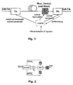
- Fig. 1 is a schematic diagram of a typical system setup according to the invention;
- Fig. 2 is a schematic diagram of a transmitter according to the invention;
- Fig. 3 is a schematic diagram of a receiver according to the invention;
- On figure 1 is shown a transmission system consisting of a transmitter, a multiplexer, fiber links with add and drop multiplexer and a demultiplexer before the receiver. The optical components (MUX, ADM, DEMUX) may act as optical filters due to their limited bandwidth. On figure 2 is shown a transmitter for generating optical PSBT signals as used for the present invention. It consists of a precoder, electrical low pass filters and a push-pull modulator or Mach-Zehnder interferometer (MZI). The bandwidth limited PSBT signal is generated by precoding and low pass filtering of the non-inverted and inverted precoded data streams. Latter precoded signal drive the dual drive MZI. The cut-off frequency of the electrical low pass filters is about 30% of bit rate frequency. After being filtered by the low pass filter, a three level signal with "-1", "0", and "1" is then available, which is necessary to generate the three level PSBT optical signal.
- The electrical low pass filters are optimised according to the present invention for the whole system. The optimisation is realised using variable electrical low pass filters while the variation consists on the possibility to adapt the cut off frequency of that filters by more than 20%. Also, an additional tuneable optical filter can be used which cuts the spectra leading to a reduction of field components at logical "0". The optimisation of the filters particularly the electrical low pass filters, needs the knowledge of optical channel and the receiver i.e. to know all the characteristics of the links within the optical transmission system as well as the receiver characteristic. The setting of the transmitter for the optimization can be performed following different possibilities. One possibility is to use a look up table with predefined values corresponding to an optical transmission system with well known links and receiver characteristics. It has the big advantage that no feed back signal must be collected and can be therefore quite cost effective. But it is rather sensible to any changes or instabilities within the optical transmission system.
- An alternative for the optimization can be achieved using some feedback signal. Such signal can be collected from the receiver via back channel or generated in the receiver. As shown on figure 1, a control apparatus collects that feedback signal to control accordingly the cut off frequency of the electrical variable low pass filters. The cut off frequency can be chosen at around 3 GHz and be varied by 20% i.e. ± 300 MHz till achieving maximal performance i.e. minimal bit errors. Alternately, the feed back signal is generated at the transmitter behind the optical filter when placed on the transmitter side.
- In this application at least one optical filter can be applied to realise a system with optical bandwidth limitation. The bandwidth limitation may be realised by separate filters, by optical network elements or by both. The setting/choice of optical filters can be performed by considering the whole channel. Dependent on application the lowest bandwidth filter is possibly placed at receiver side.
- On figure 3 is shown an example of a receiver according to the invention with a lowest electrical bandwidth filter placed after the diode acting as an optical/electrical converter. Also is placed at the input of that receiver the tuneable optical band pass filter. In some other alternatives, that tuneable optical band pass filter can be placed at the output of the transmitter or simply omitted since the corresponding properties being already obtained by the different elements within the optical transmission system. On the embodiment according to figure 3, the receiver is assembled with an analog/digital converter ADC and a digital Viterbi equalizer. A residual chromatic dispersion compensation RCDC can be applied optionally. The optical filter is adjusted with same boundary conditions as the Tx filter. If possibly, no filter is in the Tx and lowest bandwidth filter is applied in Rx. The adaptation of RCDC can be performed by the Viterbi channel estimator. In another implementation, the RCDC is adjusted by a chromatic dispersion sensitive feedback or by an eye monitor. A further implementation considers a variable optical filter with feedback from channel estimator or eye monitor. Due to interaction of feedback signal, variable filter in Rx any suboptimum setting can be avoided.
- The optimization using e.g. feedback is required at least once during installation. If a Viterbi equalizer is used at the receiver, then the electrical bandwidth in Tx is preferably 105% of the optimum bandwidth of standard Rx. The electrical bandwidth of Rx is set to 90% of optimum bandwidth for standard Rx. A comprehensive investigation of strongly bandwidth limited PSBT systems at 43 Gb/s was carried out to evaluate the dispersion tolerances in electronic dispersion compensation supported receivers. The application of Viterbi equalizers enables the reduction of optical bandwidth down to 30 GHz, whereas the standard receiver degrades already below 38 GHz. Viterbi equalization enables additional bandwidth limitation by another 30%. Even at low bandwidth high dispersion tolerances of 20 ps differential group delay (DGD) and 235 ps/nm chromatic dispersion (CD) have been achieved. A low optical bandwidth in combination with Viterbi equalizer application suppresses the system degradation at zero dispersion completely. Hence the application Viterbi equalizers in bandwidth limited PSBT systems gives high margin in optical bandwidth with a 30% reduced lower limit, increased CD and DGD tolerances by 10% and 50%, respectively, reducing the requirements on system application especially of 50 GHz spaced DWDM systems.
Claims (14)
- A method to optimize the transmission of Duobinary or Phase Shaped Binary Transmission /PSBT/ signals over an optical transmission system comprising the following steps:• precoding a data stream to be transmitted over the optical transmission system;• generating out of that precoded data stream a three level electrical signal using variable electrical low pass filter;• feeding that electrical signal to an interferometer or push-pull modulator to generate a corresponding optical PSBT signal;• forwarding that optical PSBT signal through a tuneable optical band pass filter wherein an optimization of transmission quality over the optical transmission system is reached by adapting the bandwidth of the variable electrical low pass filter with respect to the chosen bandwidth of the optical filter.
- The method according to claim 1 wherein the generated optical PSBT signal is forwarded through the tuneable optical band pass filter at the receiver after being transmitted over the optical transmission system.
- The method according to claim 1 wherein the adaptation of the electrical low pass filter together with the optical band pass filter is performed using look up table with predefined values corresponding to an optical transmission system with known links and receiver characteristics.
- The method according to claim 1 wherein the adaptation of the electrical low pass filter together with the optical band pass filter is performed using a feedback signal.
- The method according to claim 4 wherein the feedback signal is obtained at the output of the optical filter.
- The method according to claim 1 wherein the bandwidth of the optical band pass filter is selected with respect to the bandwidth of the channel within which the optical signal are transmitted over the optical transmission network.
- The method according to claim 1 wherein both the low pass filter and the band pass filter are adapted to a non optimum eye opening at transmission side setting the optical zero to a minimum magnitude.
- The method according to claim 1 wherein the optimization of transmission quality is performed taking into account a receiver comprising a Viterbi equalizer.
- A transmitter for generating Duobinary or Phase Shaped Binary Transmission /PSBT/ signals comprises a precoder for precoding a data stream to be transmitted over an optical transmission system, variable electrical low pass filter for generating a three level electrical signal out of that precoded data stream, an interferometer or push-pull modulator feed with that three level electrical signal to generate a corresponding optical PSBT signal wherein the bandwidth of the variable electrical low pass filter is adapted with respect to the chosen bandwidth of a tuneable optical filter through which the optical PSBT signal is forwarded to optimize the transmission quality over the optical transmission system.
- The transmitter according to claim 9 wherein it comprises the tuneable optical band pass filter at its output.
- The transmitter according to claim 9 wherein it is connected to feedback signal path to be used for the optimization.
- A system for optimized transmission of Duobinary or Phase Shaped Binary Transmission /PSBT/ signals comprising a transmitter for generating PSBT signals with a precoder for precoding a data stream to be transmitted over an optical transmission system being part of that system, variable electrical low pass filter for generating a three level electrical signal out of that precoded data stream, an interferometer or push-pull modulator feed with that three level electrical signal to generate a corresponding optical PSBT signal and a receiver interconnected with the transmitter via the optical transmission system wherein the bandwidth of the variable electrical low pass filter is adapted with respect to the chosen bandwidth of a tuneable optical filter being part of that system and through which the optical PSBT signal is forwarded to optimize the transmission quality over the optical transmission system.
- The system according to claim 12 wherein the receiver comprises at its input the tuneable optical band pass filter.
- The system according to claim 12 wherein the receiver comprises a Viterbi equalizer.
Priority Applications (3)
| Application Number | Priority Date | Filing Date | Title |
|---|---|---|---|
| EP06301016A EP1909413B1 (en) | 2006-10-05 | 2006-10-05 | Improved bandwidth limited PSBT system |
| DE602006019258T DE602006019258D1 (en) | 2006-10-05 | 2006-10-05 | Improved PSBT system with limited bandwidth |
| AT06301016T ATE493806T1 (en) | 2006-10-05 | 2006-10-05 | IMPROVED PSBT SYSTEM WITH LIMITED BANDWIDTH |
Applications Claiming Priority (1)
| Application Number | Priority Date | Filing Date | Title |
|---|---|---|---|
| EP06301016A EP1909413B1 (en) | 2006-10-05 | 2006-10-05 | Improved bandwidth limited PSBT system |
Publications (2)
| Publication Number | Publication Date |
|---|---|
| EP1909413A1 true EP1909413A1 (en) | 2008-04-09 |
| EP1909413B1 EP1909413B1 (en) | 2010-12-29 |
Family
ID=37776450
Family Applications (1)
| Application Number | Title | Priority Date | Filing Date |
|---|---|---|---|
| EP06301016A Not-in-force EP1909413B1 (en) | 2006-10-05 | 2006-10-05 | Improved bandwidth limited PSBT system |
Country Status (3)
| Country | Link |
|---|---|
| EP (1) | EP1909413B1 (en) |
| AT (1) | ATE493806T1 (en) |
| DE (1) | DE602006019258D1 (en) |
Cited By (2)
| Publication number | Priority date | Publication date | Assignee | Title |
|---|---|---|---|---|
| US20170187442A1 (en) * | 2015-03-16 | 2017-06-29 | Lockheed Martin Corporation | Apparatus and method for increased data rates in underwater communications using orbital angular momentum |
| CN120150829A (en) * | 2025-04-01 | 2025-06-13 | 北京理工大学 | A bandwidth limitation and electric dispersion collaborative pre-compensation method based on improved GS algorithm |
Citations (2)
| Publication number | Priority date | Publication date | Assignee | Title |
|---|---|---|---|---|
| US6623188B1 (en) * | 2002-02-08 | 2003-09-23 | Optiuh Corporation | Dispersion tolerant optical data transmitter |
| US20040101314A1 (en) * | 2002-11-22 | 2004-05-27 | Han-Lim Lee | Duobinary optical transmission apparatus |
-
2006
- 2006-10-05 EP EP06301016A patent/EP1909413B1/en not_active Not-in-force
- 2006-10-05 DE DE602006019258T patent/DE602006019258D1/en active Active
- 2006-10-05 AT AT06301016T patent/ATE493806T1/en not_active IP Right Cessation
Patent Citations (2)
| Publication number | Priority date | Publication date | Assignee | Title |
|---|---|---|---|---|
| US6623188B1 (en) * | 2002-02-08 | 2003-09-23 | Optiuh Corporation | Dispersion tolerant optical data transmitter |
| US20040101314A1 (en) * | 2002-11-22 | 2004-05-27 | Han-Lim Lee | Duobinary optical transmission apparatus |
Cited By (3)
| Publication number | Priority date | Publication date | Assignee | Title |
|---|---|---|---|---|
| US20170187442A1 (en) * | 2015-03-16 | 2017-06-29 | Lockheed Martin Corporation | Apparatus and method for increased data rates in underwater communications using orbital angular momentum |
| US10103799B2 (en) * | 2015-03-16 | 2018-10-16 | Lockheed Martin Corporation | Apparatus and method for increased data rates in underwater communications using orbital angular momentum |
| CN120150829A (en) * | 2025-04-01 | 2025-06-13 | 北京理工大学 | A bandwidth limitation and electric dispersion collaborative pre-compensation method based on improved GS algorithm |
Also Published As
| Publication number | Publication date |
|---|---|
| DE602006019258D1 (en) | 2011-02-10 |
| EP1909413B1 (en) | 2010-12-29 |
| ATE493806T1 (en) | 2011-01-15 |
Similar Documents
| Publication | Publication Date | Title |
|---|---|---|
| US10484123B2 (en) | Apparatus and method for distributed compensation of narrow optical filtering effects in an optical network | |
| US8831439B2 (en) | Upsampling optical transmitter | |
| US7949261B2 (en) | Partial DPSK (PDPSK) transmission systems | |
| Fabrega et al. | On the filter narrowing issues in elastic optical networks | |
| US8655190B2 (en) | Wavelength division multiplexed optical communication system architectures | |
| US8768177B2 (en) | Wavelength division multiplexed optical communication system having variable channel spacings | |
| US7965950B2 (en) | Performance optimized receiver with bandwidth adaptive optical filter for high speed long haul WDM systems | |
| US8639118B2 (en) | Wavelength division multiplexed optical communication system having variable channel spacings and different modulation formats | |
| CN102124671B (en) | System and method for receiving high spectral efficiency optical DPSK signals | |
| US8693873B2 (en) | Apparatus and method for improved distributed compensation of filtering effects mitigation in an optical network | |
| US8098996B2 (en) | Adaptable duobinary generating filters, transmitters, systems and methods | |
| US20130251082A1 (en) | Digital receiver and waveform compensation method | |
| US20080175594A1 (en) | Method and Apparatus for Generating Optical Duobinary Signals with Enhanced Receiver Sensitivity and Spectral Efficiency | |
| EP1909413B1 (en) | Improved bandwidth limited PSBT system | |
| KR20090067162A (en) | Method and receiver for increasing the spectral efficiency of the DSP modulation format | |
| WO2014141260A1 (en) | Pre-compensation of chromatic dispersion using coherent-less dsp | |
| EP1832026B1 (en) | Method for mitigating dispersion slope in an optical communication system | |
| EP1788734B1 (en) | Method of transmitting an optical signal and transmission system | |
| JP4199611B2 (en) | Optical wavelength division multiplexing equipment | |
| Buchali | Electronic dispersion compensation in bandwidth limited 43 Gb/s PSBT systems for 50 GHz spaced DWDM application | |
| Hewitt | Design and performance of optical vestigial sideband filters in digital 40 Gbit/s systems | |
| Nakamura et al. | DWDM Systems Migration Towards 40Gb/s |
Legal Events
| Date | Code | Title | Description |
|---|---|---|---|
| PUAI | Public reference made under article 153(3) epc to a published international application that has entered the european phase |
Free format text: ORIGINAL CODE: 0009012 |
|
| 17P | Request for examination filed |
Effective date: 20070906 |
|
| AK | Designated contracting states |
Kind code of ref document: A1 Designated state(s): AT BE BG CH CY CZ DE DK EE ES FI FR GB GR HU IE IS IT LI LT LU LV MC NL PL PT RO SE SI SK TR |
|
| AX | Request for extension of the european patent |
Extension state: AL BA HR MK RS |
|
| 17Q | First examination report despatched |
Effective date: 20081021 |
|
| AKX | Designation fees paid |
Designated state(s): AT BE BG CH CY CZ DE DK EE ES FI FR GB GR HU IE IS IT LI LT LU LV MC NL PL PT RO SE SI SK TR |
|
| GRAP | Despatch of communication of intention to grant a patent |
Free format text: ORIGINAL CODE: EPIDOSNIGR1 |
|
| GRAS | Grant fee paid |
Free format text: ORIGINAL CODE: EPIDOSNIGR3 |
|
| GRAA | (expected) grant |
Free format text: ORIGINAL CODE: 0009210 |
|
| AK | Designated contracting states |
Kind code of ref document: B1 Designated state(s): AT BE BG CH CY CZ DE DK EE ES FI FR GB GR HU IE IS IT LI LT LU LV MC NL PL PT RO SE SI SK TR |
|
| REG | Reference to a national code |
Ref country code: GB Ref legal event code: FG4D |
|
| REG | Reference to a national code |
Ref country code: CH Ref legal event code: EP |
|
| REG | Reference to a national code |
Ref country code: IE Ref legal event code: FG4D |
|
| REF | Corresponds to: |
Ref document number: 602006019258 Country of ref document: DE Date of ref document: 20110210 Kind code of ref document: P |
|
| REG | Reference to a national code |
Ref country code: DE Ref legal event code: R096 Ref document number: 602006019258 Country of ref document: DE Effective date: 20110210 |
|
| REG | Reference to a national code |
Ref country code: NL Ref legal event code: VDEP Effective date: 20101229 |
|
| PG25 | Lapsed in a contracting state [announced via postgrant information from national office to epo] |
Ref country code: LT Free format text: LAPSE BECAUSE OF FAILURE TO SUBMIT A TRANSLATION OF THE DESCRIPTION OR TO PAY THE FEE WITHIN THE PRESCRIBED TIME-LIMIT Effective date: 20101229 |
|
| LTIE | Lt: invalidation of european patent or patent extension |
Effective date: 20101229 |
|
| PG25 | Lapsed in a contracting state [announced via postgrant information from national office to epo] |
Ref country code: LV Free format text: LAPSE BECAUSE OF FAILURE TO SUBMIT A TRANSLATION OF THE DESCRIPTION OR TO PAY THE FEE WITHIN THE PRESCRIBED TIME-LIMIT Effective date: 20101229 Ref country code: SI Free format text: LAPSE BECAUSE OF FAILURE TO SUBMIT A TRANSLATION OF THE DESCRIPTION OR TO PAY THE FEE WITHIN THE PRESCRIBED TIME-LIMIT Effective date: 20101229 Ref country code: CY Free format text: LAPSE BECAUSE OF FAILURE TO SUBMIT A TRANSLATION OF THE DESCRIPTION OR TO PAY THE FEE WITHIN THE PRESCRIBED TIME-LIMIT Effective date: 20101229 Ref country code: BG Free format text: LAPSE BECAUSE OF FAILURE TO SUBMIT A TRANSLATION OF THE DESCRIPTION OR TO PAY THE FEE WITHIN THE PRESCRIBED TIME-LIMIT Effective date: 20110329 Ref country code: AT Free format text: LAPSE BECAUSE OF FAILURE TO SUBMIT A TRANSLATION OF THE DESCRIPTION OR TO PAY THE FEE WITHIN THE PRESCRIBED TIME-LIMIT Effective date: 20101229 Ref country code: SE Free format text: LAPSE BECAUSE OF FAILURE TO SUBMIT A TRANSLATION OF THE DESCRIPTION OR TO PAY THE FEE WITHIN THE PRESCRIBED TIME-LIMIT Effective date: 20101229 Ref country code: FI Free format text: LAPSE BECAUSE OF FAILURE TO SUBMIT A TRANSLATION OF THE DESCRIPTION OR TO PAY THE FEE WITHIN THE PRESCRIBED TIME-LIMIT Effective date: 20101229 |
|
| PG25 | Lapsed in a contracting state [announced via postgrant information from national office to epo] |
Ref country code: GR Free format text: LAPSE BECAUSE OF FAILURE TO SUBMIT A TRANSLATION OF THE DESCRIPTION OR TO PAY THE FEE WITHIN THE PRESCRIBED TIME-LIMIT Effective date: 20110330 Ref country code: BE Free format text: LAPSE BECAUSE OF FAILURE TO SUBMIT A TRANSLATION OF THE DESCRIPTION OR TO PAY THE FEE WITHIN THE PRESCRIBED TIME-LIMIT Effective date: 20101229 Ref country code: IS Free format text: LAPSE BECAUSE OF FAILURE TO SUBMIT A TRANSLATION OF THE DESCRIPTION OR TO PAY THE FEE WITHIN THE PRESCRIBED TIME-LIMIT Effective date: 20110429 Ref country code: CZ Free format text: LAPSE BECAUSE OF FAILURE TO SUBMIT A TRANSLATION OF THE DESCRIPTION OR TO PAY THE FEE WITHIN THE PRESCRIBED TIME-LIMIT Effective date: 20101229 Ref country code: PT Free format text: LAPSE BECAUSE OF FAILURE TO SUBMIT A TRANSLATION OF THE DESCRIPTION OR TO PAY THE FEE WITHIN THE PRESCRIBED TIME-LIMIT Effective date: 20110429 Ref country code: EE Free format text: LAPSE BECAUSE OF FAILURE TO SUBMIT A TRANSLATION OF THE DESCRIPTION OR TO PAY THE FEE WITHIN THE PRESCRIBED TIME-LIMIT Effective date: 20101229 Ref country code: ES Free format text: LAPSE BECAUSE OF FAILURE TO SUBMIT A TRANSLATION OF THE DESCRIPTION OR TO PAY THE FEE WITHIN THE PRESCRIBED TIME-LIMIT Effective date: 20110409 |
|
| PG25 | Lapsed in a contracting state [announced via postgrant information from national office to epo] |
Ref country code: PL Free format text: LAPSE BECAUSE OF FAILURE TO SUBMIT A TRANSLATION OF THE DESCRIPTION OR TO PAY THE FEE WITHIN THE PRESCRIBED TIME-LIMIT Effective date: 20101229 Ref country code: NL Free format text: LAPSE BECAUSE OF FAILURE TO SUBMIT A TRANSLATION OF THE DESCRIPTION OR TO PAY THE FEE WITHIN THE PRESCRIBED TIME-LIMIT Effective date: 20101229 Ref country code: RO Free format text: LAPSE BECAUSE OF FAILURE TO SUBMIT A TRANSLATION OF THE DESCRIPTION OR TO PAY THE FEE WITHIN THE PRESCRIBED TIME-LIMIT Effective date: 20101229 Ref country code: SK Free format text: LAPSE BECAUSE OF FAILURE TO SUBMIT A TRANSLATION OF THE DESCRIPTION OR TO PAY THE FEE WITHIN THE PRESCRIBED TIME-LIMIT Effective date: 20101229 |
|
| PG25 | Lapsed in a contracting state [announced via postgrant information from national office to epo] |
Ref country code: DK Free format text: LAPSE BECAUSE OF FAILURE TO SUBMIT A TRANSLATION OF THE DESCRIPTION OR TO PAY THE FEE WITHIN THE PRESCRIBED TIME-LIMIT Effective date: 20101229 |
|
| PLBE | No opposition filed within time limit |
Free format text: ORIGINAL CODE: 0009261 |
|
| STAA | Information on the status of an ep patent application or granted ep patent |
Free format text: STATUS: NO OPPOSITION FILED WITHIN TIME LIMIT |
|
| 26N | No opposition filed |
Effective date: 20110930 |
|
| REG | Reference to a national code |
Ref country code: DE Ref legal event code: R097 Ref document number: 602006019258 Country of ref document: DE Effective date: 20110930 |
|
| REG | Reference to a national code |
Ref country code: CH Ref legal event code: PCOW Free format text: ALCATEL LUCENT;3, AVENUE OCTAVE GREARD;75007 PARIS (FR) |
|
| PG25 | Lapsed in a contracting state [announced via postgrant information from national office to epo] |
Ref country code: MC Free format text: LAPSE BECAUSE OF NON-PAYMENT OF DUE FEES Effective date: 20111031 Ref country code: IT Free format text: LAPSE BECAUSE OF FAILURE TO SUBMIT A TRANSLATION OF THE DESCRIPTION OR TO PAY THE FEE WITHIN THE PRESCRIBED TIME-LIMIT Effective date: 20101229 |
|
| REG | Reference to a national code |
Ref country code: CH Ref legal event code: PL |
|
| PG25 | Lapsed in a contracting state [announced via postgrant information from national office to epo] |
Ref country code: LI Free format text: LAPSE BECAUSE OF NON-PAYMENT OF DUE FEES Effective date: 20111031 Ref country code: CH Free format text: LAPSE BECAUSE OF NON-PAYMENT OF DUE FEES Effective date: 20111031 |
|
| REG | Reference to a national code |
Ref country code: IE Ref legal event code: MM4A |
|
| PG25 | Lapsed in a contracting state [announced via postgrant information from national office to epo] |
Ref country code: IE Free format text: LAPSE BECAUSE OF NON-PAYMENT OF DUE FEES Effective date: 20111005 |
|
| PG25 | Lapsed in a contracting state [announced via postgrant information from national office to epo] |
Ref country code: LU Free format text: LAPSE BECAUSE OF NON-PAYMENT OF DUE FEES Effective date: 20111005 |
|
| PG25 | Lapsed in a contracting state [announced via postgrant information from national office to epo] |
Ref country code: TR Free format text: LAPSE BECAUSE OF FAILURE TO SUBMIT A TRANSLATION OF THE DESCRIPTION OR TO PAY THE FEE WITHIN THE PRESCRIBED TIME-LIMIT Effective date: 20101229 |
|
| REG | Reference to a national code |
Ref country code: GB Ref legal event code: 732E Free format text: REGISTERED BETWEEN 20130926 AND 20131002 |
|
| PG25 | Lapsed in a contracting state [announced via postgrant information from national office to epo] |
Ref country code: HU Free format text: LAPSE BECAUSE OF FAILURE TO SUBMIT A TRANSLATION OF THE DESCRIPTION OR TO PAY THE FEE WITHIN THE PRESCRIBED TIME-LIMIT Effective date: 20101229 |
|
| REG | Reference to a national code |
Ref country code: FR Ref legal event code: GC Effective date: 20131018 |
|
| REG | Reference to a national code |
Ref country code: FR Ref legal event code: RG Effective date: 20141016 |
|
| REG | Reference to a national code |
Ref country code: FR Ref legal event code: CA Effective date: 20150521 |
|
| REG | Reference to a national code |
Ref country code: FR Ref legal event code: CA Effective date: 20150521 |
|
| REG | Reference to a national code |
Ref country code: FR Ref legal event code: PLFP Year of fee payment: 10 |
|
| REG | Reference to a national code |
Ref country code: FR Ref legal event code: PLFP Year of fee payment: 11 |
|
| REG | Reference to a national code |
Ref country code: FR Ref legal event code: PLFP Year of fee payment: 12 |
|
| PGFP | Annual fee paid to national office [announced via postgrant information from national office to epo] |
Ref country code: FR Payment date: 20171024 Year of fee payment: 12 |
|
| REG | Reference to a national code |
Ref country code: GB Ref legal event code: 732E Free format text: REGISTERED BETWEEN 20190429 AND 20190502 |
|
| REG | Reference to a national code |
Ref country code: DE Ref legal event code: R082 Ref document number: 602006019258 Country of ref document: DE Representative=s name: MENZIETTI WETZEL, DE Ref country code: DE Ref legal event code: R081 Ref document number: 602006019258 Country of ref document: DE Owner name: PROVENANCE ASSET GROUP LLC, PITTSFORD, US Free format text: FORMER OWNER: ALCATEL LUCENT, PARIS, FR |
|
| PG25 | Lapsed in a contracting state [announced via postgrant information from national office to epo] |
Ref country code: FR Free format text: LAPSE BECAUSE OF NON-PAYMENT OF DUE FEES Effective date: 20181031 |
|
| PGFP | Annual fee paid to national office [announced via postgrant information from national office to epo] |
Ref country code: DE Payment date: 20201027 Year of fee payment: 15 Ref country code: GB Payment date: 20201029 Year of fee payment: 15 |
|
| REG | Reference to a national code |
Ref country code: DE Ref legal event code: R119 Ref document number: 602006019258 Country of ref document: DE |
|
| GBPC | Gb: european patent ceased through non-payment of renewal fee |
Effective date: 20211005 |
|
| PG25 | Lapsed in a contracting state [announced via postgrant information from national office to epo] |
Ref country code: GB Free format text: LAPSE BECAUSE OF NON-PAYMENT OF DUE FEES Effective date: 20211005 Ref country code: DE Free format text: LAPSE BECAUSE OF NON-PAYMENT OF DUE FEES Effective date: 20220503 |