EP1909362A1 - Assembly for connecting an electronic control board to the stator windings of an electric motor for roller blinds or the like - Google Patents
Assembly for connecting an electronic control board to the stator windings of an electric motor for roller blinds or the like Download PDFInfo
- Publication number
- EP1909362A1 EP1909362A1 EP07117166A EP07117166A EP1909362A1 EP 1909362 A1 EP1909362 A1 EP 1909362A1 EP 07117166 A EP07117166 A EP 07117166A EP 07117166 A EP07117166 A EP 07117166A EP 1909362 A1 EP1909362 A1 EP 1909362A1
- Authority
- EP
- European Patent Office
- Prior art keywords
- stator
- flat portion
- base
- terminals
- stator windings
- Prior art date
- Legal status (The legal status is an assumption and is not a legal conclusion. Google has not performed a legal analysis and makes no representation as to the accuracy of the status listed.)
- Granted
Links
Images


Classifications
-
- H—ELECTRICITY
- H01—ELECTRIC ELEMENTS
- H01R—ELECTRICALLY-CONDUCTIVE CONNECTIONS; STRUCTURAL ASSOCIATIONS OF A PLURALITY OF MUTUALLY-INSULATED ELECTRICAL CONNECTING ELEMENTS; COUPLING DEVICES; CURRENT COLLECTORS
- H01R12/00—Structural associations of a plurality of mutually-insulated electrical connecting elements, specially adapted for printed circuits, e.g. printed circuit boards [PCB], flat or ribbon cables, or like generally planar structures, e.g. terminal strips, terminal blocks; Coupling devices specially adapted for printed circuits, flat or ribbon cables, or like generally planar structures; Terminals specially adapted for contact with, or insertion into, printed circuits, flat or ribbon cables, or like generally planar structures
- H01R12/70—Coupling devices
- H01R12/71—Coupling devices for rigid printing circuits or like structures
- H01R12/72—Coupling devices for rigid printing circuits or like structures coupling with the edge of the rigid printed circuits or like structures
- H01R12/721—Coupling devices for rigid printing circuits or like structures coupling with the edge of the rigid printed circuits or like structures cooperating directly with the edge of the rigid printed circuits
-
- H—ELECTRICITY
- H02—GENERATION; CONVERSION OR DISTRIBUTION OF ELECTRIC POWER
- H02K—DYNAMO-ELECTRIC MACHINES
- H02K11/00—Structural association of dynamo-electric machines with electric components or with devices for shielding, monitoring or protection
- H02K11/30—Structural association with control circuits or drive circuits
- H02K11/33—Drive circuits, e.g. power electronics
-
- H—ELECTRICITY
- H02—GENERATION; CONVERSION OR DISTRIBUTION OF ELECTRIC POWER
- H02K—DYNAMO-ELECTRIC MACHINES
- H02K5/00—Casings; Enclosures; Supports
- H02K5/04—Casings or enclosures characterised by the shape, form or construction thereof
- H02K5/22—Auxiliary parts of casings not covered by groups H02K5/06-H02K5/20, e.g. shaped to form connection boxes or terminal boxes
- H02K5/225—Terminal boxes or connection arrangements
-
- E—FIXED CONSTRUCTIONS
- E06—DOORS, WINDOWS, SHUTTERS, OR ROLLER BLINDS IN GENERAL; LADDERS
- E06B—FIXED OR MOVABLE CLOSURES FOR OPENINGS IN BUILDINGS, VEHICLES, FENCES OR LIKE ENCLOSURES IN GENERAL, e.g. DOORS, WINDOWS, BLINDS, GATES
- E06B9/00—Screening or protective devices for wall or similar openings, with or without operating or securing mechanisms; Closures of similar construction
- E06B9/56—Operating, guiding or securing devices or arrangements for roll-type closures; Spring drums; Tape drums; Counterweighting arrangements therefor
- E06B9/68—Operating devices or mechanisms, e.g. with electric drive
Definitions
- the present invention relates to an assembly for connecting an electronic control board to the stator windings of an electric motor for roller blinds or the like.
- the aim of the present invention is to solve the drawbacks observed in relation to the electrical connection between electronic boards and stator windings of small motors.
- an object of the present invention is to provide an assembly for connecting an electronic control board to the stator windings of an electric motor for roller blinds or the like which allows to connect the electronic board in a position which is close to the windings.
- Another object of the present invention is to provide an assembly for connecting an electronic control board to the stator windings of an electric motor for roller blinds or the like which allows an extremely stable connection for said electronic board.
- an assembly for connecting an electronic control board to the stator windings of an electric motor for roller blinds or the like characterized in that it comprises a base which has, on a first face, means for centering on the stator of the motor at an end face of said stator, an abutment body for the stator windings protruding from said base toward the coupling to the end face of the stator, a first body for accommodating first electrical terminals for direct connection to first leads of the stator windings and a second body for accommodating second electrical terminals for direct connection to second leads of the stator windings protruding from the opposite second face of the base, said second electrical terminals being directly in electrical contact with the electronic board, said second body having a slot which intersects the seats on which said second terminals are provided, said slot being extended substantially in the same direction as said second body, the electronic board being insertable in said slot.
- an assembly for connecting an electronic control board to the stator windings of an electric motor for roller blinds or the like, according to the invention is generally designated by the reference numeral 10.
- an electric motor designated by the reference numeral 11, is of the type which has a substantially cylindrical contour; a stator 12 in fact has a cylindrical shape and stator windings 13 (shown schematically in the figures as a monolithic torus) are arranged at an end face 14 of the stator 12.
- connection assembly 10 comprises a circular base 15 made of plastic material, which has, on a first face 16, an abutment body 17 for the stator windings 13, such as a ring around which said stator windings are arranged; the outward edge of the ring 17 rests on the base 14.
- Means 18 for centering on the stator 12 protrude from the first face 16 centrally with respect to the ring 17 substantially at the base 14 of said stator; said centering means are constituted by teeth which are inserted in gaps 12a of the stator 12.
- a first body 20 for accommodating first electrical terminals 21 for connection to first leads 13a of the stator windings 13 and a second body 22 for accommodating second electrical terminals 23 connected to second leads 13b of the stator windings protrude monolithically from an opposite second face 19 of the circular base 15, in a manner shown in Figure 3.
- the second electrical terminals 23 are directly in electrical contact with an electronic board, generally designated by the reference numeral 24.
- a slot 25 is provided on the second body 22 and the board 24 can be inserted therein; said slot lies substantially in the same direction along which the second body 22 lies and intersects seats 26 on which the second terminals 23 are inserted.
- a pocket 27 for accommodating a thermal protection device 28 connected to the first and second terminals 21 and 23 is provided on the circular base 15, which is open on the second face 19.
- the first body is provided with receptacles 29 for the first terminals 21.
- the receptacles 29 are provided with respective first grooves 30, which are mutually parallel and are arranged transversely to the extension of said receptacles and pass through all of the first body 20.
- An electrical wire can be arranged on the bottom of each groove 30.
- the first leads 13a of the stator windings can be arranged on two grooves 30, while a first wire 31a for connection to the thermal protection device 28 is arranged on the remaining groove.
- the arrangement of the wires on said first grooves allows electrical contact with the first terminals 21 when they are inserted in the receptacles 29.
- the first terminals 21 are in fact constituted by plates which are provided with self-centering tapered seats 32 for accommodating the leads 13a of the stator windings 13 and for a first wire 28a.
- each first terminal 21 is constituted by mutually opposite wings 33, which are folded on the same plane of arrangement as the terminal 21, with free ends 34 which mutually converge at the axis of said plate so as to form the self-centering tapering seat 32 for accommodating a respective wire lead.
- the mutually opposite wings 33 are contoured at the mutually facing edge portions so as to form blades 35 which are adapted to cut into the enamel that covers the wires.
- the first terminals 21 are connected by strips 36 (they are provided monolithically) so as to form an electric bridge.
- the seats 26 of the second body 22 on which the second terminals 23 are inserted are provided with respective second grooves 38, which are mutually parallel, are arranged transversely to the extension of the seats 26, and pass through all of the second body 20.
- An electrical wire can be arranged on the bottom of each second groove 38.
- the arrangement of the wires on said second grooves allows electrical contact with the second terminals 23 when they are inserted in the seats 26.
- Each second terminal 23 is constituted by two flat portions.
- a first flat portion 39 is substantially similar to a single first terminal 21 and is parallel to the electronic board 24 when it is inserted in the respective seat 26.
- Said board in practice has a self-centering tapering seat 40 for accommodating the leads 13b of the stator windings 13 and for the second wire 28b.
- the first flat portion 39 is constituted by mutually opposite wings 41, which are folded on the same plane of arrangement as the first flat portion 39, with free ends 42 which mutually converge at the axis of said flat portion so as to form the self-centering tapering seat 40 for accommodating a respective wire lead.
- the mutually opposite wings 41 are contoured at the mutually facing edge portions so as to form blades 43 which are adapted to cut into the enamel that covers the wires.
- the second flat portion 44 lies at right angles to the flat extension of the first flat portion 39 and parallel to the extension of the seats 26.
- the second flat portion 44 has an open slit 45 for the insertion of the electronic board 24.
- the end regions of the slit 45 have recesses 46 for electrical contact with the electronic board 24.
- wire guiding notches 47 are provided on the edge of the base 15.
- the present invention in fact provides an assembly for connecting an electronic control board to the stator windings of an electric motor for roller blinds or the like which allows to connect the board directly to the head of the motor by means of compact connectors.
- the slot provided in the second body allows stable accommodation and electrical contact of the electronic board with the second electrical terminals.
- the shape of said terminals also helps to ensure a stable electrical contact.
- the materials employed may be any according to requirements and to the state of the art.
Landscapes
- Engineering & Computer Science (AREA)
- Power Engineering (AREA)
- Microelectronics & Electronic Packaging (AREA)
- Operating, Guiding And Securing Of Roll- Type Closing Members (AREA)
- Blinds (AREA)
- Specific Sealing Or Ventilating Devices For Doors And Windows (AREA)
- Insulation, Fastening Of Motor, Generator Windings (AREA)
Abstract
Description
- The present invention relates to an assembly for connecting an electronic control board to the stator windings of an electric motor for roller blinds or the like.
- As is known, when small electric motors are accommodated in equally small compartments, such as for example in the case of electric motors of roller blinds, which are confined within tight tubular casings, the electronic control boards of said motors, which are connected to the stator windings, are accommodated externally with respect to such compartments; the connection is derived by means of wires which are connected in various manners to the windings.
- This is necessary because direct connections by means of traditional connecting assemblies are usually bulky and not always ensure stable contact.
- It is evident that it is inconvenient, particularly for operators who perform assemblies of the automated type, to have to provide a wired connection between the windings and the electronic board.
- Moreover, there is often little space also outside the casing that contains the motor, since certain products which use small motors may be accommodated in tight spaces.
- Therefore, the presence of the electronic board (and of the covering and insulation system that it requires) can interfere with the space available.
- The aim of the present invention is to solve the drawbacks observed in relation to the electrical connection between electronic boards and stator windings of small motors.
- Within this aim, an object of the present invention is to provide an assembly for connecting an electronic control board to the stator windings of an electric motor for roller blinds or the like which allows to connect the electronic board in a position which is close to the windings.
- Another object of the present invention is to provide an assembly for connecting an electronic control board to the stator windings of an electric motor for roller blinds or the like which allows an extremely stable connection for said electronic board.
- This aim and these and other objects, which will become better apparent hereinafter, are achieved by an assembly for connecting an electronic control board to the stator windings of an electric motor for roller blinds or the like, characterized in that it comprises a base which has, on a first face, means for centering on the stator of the motor at an end face of said stator, an abutment body for the stator windings protruding from said base toward the coupling to the end face of the stator, a first body for accommodating first electrical terminals for direct connection to first leads of the stator windings and a second body for accommodating second electrical terminals for direct connection to second leads of the stator windings protruding from the opposite second face of the base, said second electrical terminals being directly in electrical contact with the electronic board, said second body having a slot which intersects the seats on which said second terminals are provided, said slot being extended substantially in the same direction as said second body, the electronic board being insertable in said slot.
- Further characteristics and advantages of the invention will become better apparent from the following detailed description of a preferred but not exclusive embodiment thereof, illustrated by way of non-limiting example in the accompanying drawings, wherein:
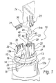
- Figure 1 is an exploded perspective view of a connection assembly according to the invention, applied to an electric motor;
- Figure 2 is a top view of the connection assembly of Figure 1;
- Figure 3 is a diagram of the electrical connections of the leads of the stator windings;
- Figure 4 is a sectional view of the connection assembly, taken along the line IV-IV of Figure 2;
- Figure 5 is a sectional view of the connection assembly, taken along the line V-V of Figure 2.
- It is noted that anything found to be already known during the patenting process is understood not to be claimed and to be the subject of a disclaimer.
- With reference to the figures, an assembly for connecting an electronic control board to the stator windings of an electric motor for roller blinds or the like, according to the invention, is generally designated by the
reference numeral 10. - As clearly shown in Figure 1, an electric motor, designated by the
reference numeral 11, is of the type which has a substantially cylindrical contour; astator 12 in fact has a cylindrical shape and stator windings 13 (shown schematically in the figures as a monolithic torus) are arranged at anend face 14 of thestator 12. - The
connection assembly 10 comprises acircular base 15 made of plastic material, which has, on afirst face 16, anabutment body 17 for thestator windings 13, such as a ring around which said stator windings are arranged; the outward edge of thering 17 rests on thebase 14. - Means 18 for centering on the
stator 12 protrude from thefirst face 16 centrally with respect to thering 17 substantially at thebase 14 of said stator; said centering means are constituted by teeth which are inserted ingaps 12a of thestator 12. - A
first body 20 for accommodating firstelectrical terminals 21 for connection to first leads 13a of thestator windings 13 and asecond body 22 for accommodating secondelectrical terminals 23 connected tosecond leads 13b of the stator windings protrude monolithically from an oppositesecond face 19 of thecircular base 15, in a manner shown in Figure 3. - The second
electrical terminals 23 are directly in electrical contact with an electronic board, generally designated by thereference numeral 24. - In order to ensure the stability of the
electronic board 24, aslot 25 is provided on thesecond body 22 and theboard 24 can be inserted therein; said slot lies substantially in the same direction along which thesecond body 22 lies and intersectsseats 26 on which thesecond terminals 23 are inserted. - Further, as shown in Figure 3, a
pocket 27 for accommodating athermal protection device 28 connected to the first andsecond terminals circular base 15, which is open on thesecond face 19. - The first body is provided with
receptacles 29 for thefirst terminals 21. - The
receptacles 29 are provided with respectivefirst grooves 30, which are mutually parallel and are arranged transversely to the extension of said receptacles and pass through all of thefirst body 20. - An electrical wire can be arranged on the bottom of each
groove 30. - In particular, in this configuration, the first leads 13a of the stator windings can be arranged on two
grooves 30, while afirst wire 31a for connection to thethermal protection device 28 is arranged on the remaining groove. - The arrangement of the wires on said first grooves allows electrical contact with the
first terminals 21 when they are inserted in thereceptacles 29. - As clearly shown in the electrical diagram of Figure 3, the
first terminals 21 are in fact constituted by plates which are provided with self-centeringtapered seats 32 for accommodating theleads 13a of thestator windings 13 and for a first wire 28a. - In particular, each
first terminal 21 is constituted by mutuallyopposite wings 33, which are folded on the same plane of arrangement as theterminal 21, withfree ends 34 which mutually converge at the axis of said plate so as to form the self-centeringtapering seat 32 for accommodating a respective wire lead. - In particular, the mutually
opposite wings 33 are contoured at the mutually facing edge portions so as to formblades 35 which are adapted to cut into the enamel that covers the wires. - As clearly shown, the
first terminals 21 are connected by strips 36 (they are provided monolithically) so as to form an electric bridge. - Like the
first body 20, theseats 26 of thesecond body 22 on which thesecond terminals 23 are inserted are provided with respectivesecond grooves 38, which are mutually parallel, are arranged transversely to the extension of theseats 26, and pass through all of thesecond body 20. - An electrical wire can be arranged on the bottom of each
second groove 38. - In particular, in this configuration, it is possible to arrange on two
second grooves 38 the second leads 13b of the stator windings, while thesecond wire 31b for connection to thethermal protection device 28 is arranged on the remaining groove. - In this case also, the arrangement of the wires on said second grooves allows electrical contact with the
second terminals 23 when they are inserted in theseats 26. - Each
second terminal 23 is constituted by two flat portions. - A first
flat portion 39 is substantially similar to a singlefirst terminal 21 and is parallel to theelectronic board 24 when it is inserted in therespective seat 26. - Said board in practice has a self-centering
tapering seat 40 for accommodating theleads 13b of thestator windings 13 and for the second wire 28b. - In particular, the first
flat portion 39 is constituted by mutuallyopposite wings 41, which are folded on the same plane of arrangement as the firstflat portion 39, withfree ends 42 which mutually converge at the axis of said flat portion so as to form the self-centeringtapering seat 40 for accommodating a respective wire lead. - In particular, the mutually
opposite wings 41 are contoured at the mutually facing edge portions so as to formblades 43 which are adapted to cut into the enamel that covers the wires. - The second
flat portion 44 lies at right angles to the flat extension of the firstflat portion 39 and parallel to the extension of theseats 26. - In particular, the second
flat portion 44 has anopen slit 45 for the insertion of theelectronic board 24. - The end regions of the
slit 45 haverecesses 46 for electrical contact with theelectronic board 24. - In practice, when each
second terminal 23 is completely inserted in thecorresponding seat 26, theslit 45 substantially follows, except for therecesses 46, the profile of theslot 25. - To ensure optimum locking of the leads of the
stator windings 13,wire guiding notches 47 are provided on the edge of thebase 15. - In practice it has been found that the invention thus described achieves the intended aim and objects.
- The present invention in fact provides an assembly for connecting an electronic control board to the stator windings of an electric motor for roller blinds or the like which allows to connect the board directly to the head of the motor by means of compact connectors.
- The slot provided in the second body allows stable accommodation and electrical contact of the electronic board with the second electrical terminals.
- The shape of said terminals also helps to ensure a stable electrical contact.
- The invention thus conceived is susceptible of numerous modifications and variations, all of which are within the scope of the appended claims; all the details may further be replaced with other technically equivalent elements.
- In practice, the materials employed, so long as they are compatible with the specific use, as well as the dimensions, may be any according to requirements and to the state of the art.
- The disclosures in
Italian Patent Application No. PD2006A000361 - Where technical features mentioned in any claim are followed by reference signs, those reference signs have been included for the sole purpose of increasing the intelligibility of the claims and accordingly such reference signs do not have any limiting effect on the interpretation of each element identified by way of example by such reference signs.
Claims (9)
- An assembly for connecting an electronic control board to the stator windings of an electric motor for roller blinds or the like, characterized in that it comprises a base (15) which has, on a first face (16), means (18) for centering on the stator (12) of the motor (11) at an end face (14) of said stator (12), an abutment body (17) for the stator windings (13) protruding from said base (15) toward the coupling to the end face (14) of the stator, a first body (20) for accommodating first electrical terminals (21) for direct connection to first leads (13a) of the stator windings (13) and a second body (22) for accommodating second electrical terminals (23) for direct connection to second leads (13b) of the stator windings (13) protruding from the opposite second face (19) of said base (15), said second electrical terminals (23) being directly in electrical contact with the electronic board (24), said second body (22) having a slot (25) which intersects the seats (26) on which said second electrical terminals (23) are provided, said slot (25) being extended substantially in the same direction as said second body (22) with respect to said base (15), the electronic board (24) being insertable in said slot (25).
- The connection assembly according to claim 1, characterized in that the receptacles (29) for said first terminals (21), formed in said first body (20), are provided with respective first grooves (30), which are mutually parallel and are arranged transversely to the extension of said receptacles (29) and pass through all of said first body (20), an electrical wire being arrangeable on the bottom of each said first groove (30).
- The connection assembly according to claim 1 or 2, characterized in that said seats (26) of said second body (22) in which said second terminals (23) are inserted are provided with respective second grooves (3 8), which are mutually parallel, are arranged transversely to the extension of said seats (26) and pass through all of said second body (20), an electrical wire being arrangeable on the bottom of each second groove (38).
- The connection assembly according to one or more of the preceding claims, characterized in that said base (15) is substantially circular and said abutment body (17) is constituted by a ring, the outward edge of which is adapted to rest against the base (14) of the stator (12), said means (18) for centering on the stator (12) being constituted by teeth which are adapted to be inserted in the gaps (12a) of said stator (12).
- The connection assembly according to one or more of the preceding claims, characterized in that a pocket (27) for accommodating a thermal protection device (28) connected to said first and second terminals (21, 23) is further provided on said base (15), which is open onto said second face (19).
- The connection assembly according to one or more of the preceding claims, characterized in that each second terminal (23) is constituted by two flat portions, a first flat portion (39) and a second flat portion (44), said first flat portion (39) being parallel to the direction of insertion in said slot (25) of the electronic board (24) when it is inserted in the respective said slot (25), said first flat portion (39) having a self-centering tapering seat (40) for accommodating electrical wires (13b, 28b), said second flat portion (44) being arranged at right angles to the flat extension of the first flat portion (39) and parallel to the extension of the respective said containment seat (26), said second flat portion (44) having an open slit (45) for the insertion of the electronic board (24), the end regions of the slit (45) having recesses (46) for electrical contact with the electronic board (24).
- The connection assembly according to claim 6, characterized in that when each of said second terminals (23) is completely inserted in the corresponding said seat (26), said slit (45) substantially follows, except for said recesses (46), the profile of said slot (25).
- The connection assembly according to claim 6, characterized in that said first flat portion (39) is constituted by mutually opposite wings (41), which are folded on the same plane of arrangement as said first flat portion (39), with free ends (42) which mutually converge at the axis of said flat portion so as to form said self-centering tapering seat (40) for accommodating a respective wire lead, said mutually opposite wings (41) being contoured at said mutually facing edge portions so as to form blades (43) which are adapted to cut into the enamel that covers the wires.
- The connection assembly according to one or more of the preceding claims, characterized in that it comprises wire guiding notches (47) on the edge of said base (15).
Applications Claiming Priority (1)
| Application Number | Priority Date | Filing Date | Title |
|---|---|---|---|
| IT000361A ITPD20060361A1 (en) | 2006-10-03 | 2006-10-03 | CONNECTION GROUP OF AN ELECTRONIC CONTROL BOARD TO THE STATIC CHARGES OF AN ELECTRIC MOTOR FOR ROLLER BLINDS OR SIMILAR |
Publications (2)
| Publication Number | Publication Date |
|---|---|
| EP1909362A1 true EP1909362A1 (en) | 2008-04-09 |
| EP1909362B1 EP1909362B1 (en) | 2010-05-12 |
Family
ID=38871580
Family Applications (1)
| Application Number | Title | Priority Date | Filing Date |
|---|---|---|---|
| EP07117166A Active EP1909362B1 (en) | 2006-10-03 | 2007-09-25 | Assembly for connecting an electronic control board to the stator windings of an electric motor for roller blinds or the like |
Country Status (5)
| Country | Link |
|---|---|
| US (1) | US7484992B2 (en) |
| EP (1) | EP1909362B1 (en) |
| AT (1) | ATE467924T1 (en) |
| DE (1) | DE602007006389D1 (en) |
| IT (1) | ITPD20060361A1 (en) |
Cited By (3)
| Publication number | Priority date | Publication date | Assignee | Title |
|---|---|---|---|---|
| WO2013000006A3 (en) * | 2011-06-29 | 2013-05-10 | Tgw Mechanics Gmbh | Conveyor roller |
| FR3067863A1 (en) * | 2017-06-19 | 2018-12-21 | Valeo Systemes De Controle Moteur | DEVICE FOR MAINTAINING A CONNECTION TAB OF AN ELECTRICAL EQUIPMENT |
| AT520107A1 (en) * | 2017-07-12 | 2019-01-15 | B & R Ind Automation Gmbh | Assembly method for a long-stator linear motor |
Families Citing this family (10)
| Publication number | Priority date | Publication date | Assignee | Title |
|---|---|---|---|---|
| ITPD20060395A1 (en) * | 2006-10-24 | 2008-04-25 | Inarca Spa | CONNECTION GROUP OF THE ELECTRIC WINDINGS OF THE STATOR OF AN ELECTRIC MOTOR |
| FR2927473B1 (en) * | 2008-02-08 | 2010-05-21 | Pompes Salmson Sa | POWER INTERFACE, POWER CONNECTOR AND ASSEMBLY THEREOF |
| DE102008001268A1 (en) * | 2008-04-18 | 2009-10-22 | Robert Bosch Gmbh | Plug arrangement in a machine tool, in particular in a hand tool |
| TW201143210A (en) * | 2010-05-28 | 2011-12-01 | Excel Cell Elect Co Ltd | Thin type connector |
| TR201718720T3 (en) * | 2011-12-29 | 2017-12-21 | Arcelik As | Thermal motor. |
| KR102212950B1 (en) * | 2015-01-07 | 2021-02-05 | 엘지이노텍 주식회사 | Motor |
| US9831580B2 (en) | 2015-09-15 | 2017-11-28 | Ghsp, Inc. | Vehicle-mounted sensorless motor with edge-connected termination |
| FR3072116B1 (en) * | 2017-10-10 | 2019-11-08 | Somfy Activites Sa | TUBULAR ELECTROMECHANICAL ACTUATOR AND DOMOTIC INSTALLATION COMPRISING SUCH ACTUATOR |
| US12057754B2 (en) * | 2019-09-30 | 2024-08-06 | Jiangsu Leili Motor Co., Ltd. | Motor with flame-resistant terminal connecting device and lead portion |
| US12556055B2 (en) * | 2022-01-24 | 2026-02-17 | Techtronic Cordless Gp | Electrical interconnector and motor including the same |
Citations (4)
| Publication number | Priority date | Publication date | Assignee | Title |
|---|---|---|---|---|
| DE3509188A1 (en) * | 1985-03-14 | 1986-09-18 | Deutsche Vortex GmbH, 4050 Mönchengladbach | Electrical spherical motor |
| US5412271A (en) * | 1993-08-25 | 1995-05-02 | Molex Incorporated | Small sized electric motor equipped with an electric connector |
| US6177741B1 (en) * | 1998-09-15 | 2001-01-23 | Wilo Gmbh | Electric-motor wiring system |
| US20030193768A1 (en) * | 2002-04-15 | 2003-10-16 | Inarca S.P.A. | Device for connecting and insulating a thermal protector and/or a fuse for electrical windings of motors |
Family Cites Families (14)
| Publication number | Priority date | Publication date | Assignee | Title |
|---|---|---|---|---|
| US4533202A (en) * | 1983-09-29 | 1985-08-06 | The Siemon Company | Multiple electrical connector and block with printed circuit board connector clip |
| NL8503347A (en) * | 1985-12-04 | 1987-07-01 | Du Pont Nederland | CONNECTOR. |
| US6348752B1 (en) * | 1992-04-06 | 2002-02-19 | General Electric Company | Integral motor and control |
| IT1287968B1 (en) * | 1996-10-18 | 1998-09-10 | Inarca Spa | CONNECTION GROUP FOR THE WINDINGS OF A STATOR OF AN ELECTRIC MOTOR |
| US6756711B2 (en) * | 2000-12-27 | 2004-06-29 | Asmo Co., Ltd. | Motor having control circuit board for controlling its rotation |
| ITPD20010010A1 (en) * | 2001-01-16 | 2002-07-16 | Inarca Spa | PERFECTED ELECTRIC CONNECTOR |
| ITPD20010016U1 (en) * | 2001-03-01 | 2002-09-02 | Inarca Spa | DEVICE FOR THE CONNECTION AND INSULATION OF A THERMAL PROTECTOR FOR ELECTRIC WINDINGS OF MOTORS. |
| DE10140910C2 (en) * | 2001-08-21 | 2003-07-17 | Lumberg Automation Components | Electrical connector |
| ITPD20040026U1 (en) * | 2004-03-17 | 2004-06-17 | Inarca Spa | PERFECTED ELECTRIC CONNECTOR FOR WINDING IN THE COIL |
| ITPD20050100U1 (en) * | 2005-12-23 | 2007-06-24 | Inarca Spa | ELECTRICAL CABLES CONNECTOR WITH ELECTRONIC BOARDS, PARTICULARLY FOR WIRING OF HOME AUTOMATION NETWORKS |
| ITPD20060362A1 (en) * | 2006-10-03 | 2008-04-04 | Inarca Spa | ¿GROUP OF CONNECTION OF THE STATIC CHARGES OF AN ELECTRIC MOTOR WITH RESPECTIVE POWER SUPPLY¿ |
| ITPD20060394A1 (en) * | 2006-10-24 | 2008-04-25 | Inarca Spa | CONNECTION GROUP OF THE STATIC FUNCTIONS OF AN ELECTRIC MOTOR |
| ITPD20060395A1 (en) * | 2006-10-24 | 2008-04-25 | Inarca Spa | CONNECTION GROUP OF THE ELECTRIC WINDINGS OF THE STATOR OF AN ELECTRIC MOTOR |
| JP4964612B2 (en) * | 2007-02-19 | 2012-07-04 | マブチモーター株式会社 | Optical encoder device for small motor |
-
2006
- 2006-10-03 IT IT000361A patent/ITPD20060361A1/en unknown
-
2007
- 2007-09-25 EP EP07117166A patent/EP1909362B1/en active Active
- 2007-09-25 AT AT07117166T patent/ATE467924T1/en not_active IP Right Cessation
- 2007-09-25 DE DE602007006389T patent/DE602007006389D1/en active Active
- 2007-10-01 US US11/905,425 patent/US7484992B2/en active Active
Patent Citations (4)
| Publication number | Priority date | Publication date | Assignee | Title |
|---|---|---|---|---|
| DE3509188A1 (en) * | 1985-03-14 | 1986-09-18 | Deutsche Vortex GmbH, 4050 Mönchengladbach | Electrical spherical motor |
| US5412271A (en) * | 1993-08-25 | 1995-05-02 | Molex Incorporated | Small sized electric motor equipped with an electric connector |
| US6177741B1 (en) * | 1998-09-15 | 2001-01-23 | Wilo Gmbh | Electric-motor wiring system |
| US20030193768A1 (en) * | 2002-04-15 | 2003-10-16 | Inarca S.P.A. | Device for connecting and insulating a thermal protector and/or a fuse for electrical windings of motors |
Cited By (3)
| Publication number | Priority date | Publication date | Assignee | Title |
|---|---|---|---|---|
| WO2013000006A3 (en) * | 2011-06-29 | 2013-05-10 | Tgw Mechanics Gmbh | Conveyor roller |
| FR3067863A1 (en) * | 2017-06-19 | 2018-12-21 | Valeo Systemes De Controle Moteur | DEVICE FOR MAINTAINING A CONNECTION TAB OF AN ELECTRICAL EQUIPMENT |
| AT520107A1 (en) * | 2017-07-12 | 2019-01-15 | B & R Ind Automation Gmbh | Assembly method for a long-stator linear motor |
Also Published As
| Publication number | Publication date |
|---|---|
| US20080022597A1 (en) | 2008-01-31 |
| EP1909362B1 (en) | 2010-05-12 |
| ITPD20060361A1 (en) | 2008-04-04 |
| DE602007006389D1 (en) | 2010-06-24 |
| US7484992B2 (en) | 2009-02-03 |
| ATE467924T1 (en) | 2010-05-15 |
Similar Documents
| Publication | Publication Date | Title |
|---|---|---|
| EP1909362B1 (en) | Assembly for connecting an electronic control board to the stator windings of an electric motor for roller blinds or the like | |
| US10396616B2 (en) | Electric motor and switching unit therefor | |
| US4513214A (en) | Dynamoelectric machine | |
| US20080150377A1 (en) | Insulating motor housing | |
| US11936262B2 (en) | Electric motor and switching unit therefor | |
| US3293463A (en) | Lead positioner and anchor for dynamoelectric machines | |
| CN107086694B (en) | Electric contact for an electric motor | |
| US8198780B2 (en) | Stator for an electronically commutated DC motor | |
| JP4746353B2 (en) | Electromagnetic coil lead wire holding structure | |
| JP2005341640A (en) | Stator of motor | |
| US20040150275A1 (en) | Stator structure for a resolver | |
| US5373209A (en) | Assembled commutator | |
| Brettschneider et al. | Flexible mass production concept for segmented BLDC stators | |
| US10468940B2 (en) | Motor and stator thereof | |
| EP1115191B1 (en) | Connection assembly particularly for the windings of a stator of an electric motor | |
| EP3566239B1 (en) | Thermally protected bobbin assembly | |
| EP1355406A1 (en) | Device for connecting and insulating a thermal protector and/or a fuse for electrical windings of motors | |
| US5729064A (en) | Multi-pole electric motor with brush holder device having two terminal assemblies | |
| US20170279338A1 (en) | Motor, stator and method of forming the stator | |
| CN211018504U (en) | Axial flow motor | |
| JP3924187B2 (en) | connector | |
| EP1441433B1 (en) | Connection assembly, particular for the stator windings of an electric motor | |
| CN112531948A (en) | Coil framework and stator framework | |
| US4868905A (en) | Motor and other apparatus with novel power lead attachment structure | |
| CN107408788A (en) | Electrical equipment with terminal and wire stripping seat |
Legal Events
| Date | Code | Title | Description |
|---|---|---|---|
| PUAI | Public reference made under article 153(3) epc to a published international application that has entered the european phase |
Free format text: ORIGINAL CODE: 0009012 |
|
| AK | Designated contracting states |
Kind code of ref document: A1 Designated state(s): AT BE BG CH CY CZ DE DK EE ES FI FR GB GR HU IE IS IT LI LT LU LV MC MT NL PL PT RO SE SI SK TR |
|
| AX | Request for extension of the european patent |
Extension state: AL BA HR MK RS |
|
| 17P | Request for examination filed |
Effective date: 20080923 |
|
| AKX | Designation fees paid |
Designated state(s): AT BE BG CH CY CZ DE DK EE ES FI FR GB GR HU IE IS IT LI LT LU LV MC MT NL PL PT RO SE SI SK TR |
|
| GRAP | Despatch of communication of intention to grant a patent |
Free format text: ORIGINAL CODE: EPIDOSNIGR1 |
|
| GRAS | Grant fee paid |
Free format text: ORIGINAL CODE: EPIDOSNIGR3 |
|
| GRAA | (expected) grant |
Free format text: ORIGINAL CODE: 0009210 |
|
| AK | Designated contracting states |
Kind code of ref document: B1 Designated state(s): AT BE BG CH CY CZ DE DK EE ES FI FR GB GR HU IE IS IT LI LT LU LV MC MT NL PL PT RO SE SI SK TR |
|
| REG | Reference to a national code |
Ref country code: GB Ref legal event code: FG4D |
|
| REG | Reference to a national code |
Ref country code: CH Ref legal event code: EP |
|
| REG | Reference to a national code |
Ref country code: IE Ref legal event code: FG4D |
|
| REF | Corresponds to: |
Ref document number: 602007006389 Country of ref document: DE Date of ref document: 20100624 Kind code of ref document: P |
|
| REG | Reference to a national code |
Ref country code: NL Ref legal event code: VDEP Effective date: 20100512 |
|
| LTIE | Lt: invalidation of european patent or patent extension |
Effective date: 20100512 |
|
| PG25 | Lapsed in a contracting state [announced via postgrant information from national office to epo] |
Ref country code: NL Free format text: LAPSE BECAUSE OF FAILURE TO SUBMIT A TRANSLATION OF THE DESCRIPTION OR TO PAY THE FEE WITHIN THE PRESCRIBED TIME-LIMIT Effective date: 20100512 Ref country code: SE Free format text: LAPSE BECAUSE OF FAILURE TO SUBMIT A TRANSLATION OF THE DESCRIPTION OR TO PAY THE FEE WITHIN THE PRESCRIBED TIME-LIMIT Effective date: 20100512 Ref country code: ES Free format text: LAPSE BECAUSE OF FAILURE TO SUBMIT A TRANSLATION OF THE DESCRIPTION OR TO PAY THE FEE WITHIN THE PRESCRIBED TIME-LIMIT Effective date: 20100823 Ref country code: LT Free format text: LAPSE BECAUSE OF FAILURE TO SUBMIT A TRANSLATION OF THE DESCRIPTION OR TO PAY THE FEE WITHIN THE PRESCRIBED TIME-LIMIT Effective date: 20100512 |
|
| PG25 | Lapsed in a contracting state [announced via postgrant information from national office to epo] |
Ref country code: IS Free format text: LAPSE BECAUSE OF FAILURE TO SUBMIT A TRANSLATION OF THE DESCRIPTION OR TO PAY THE FEE WITHIN THE PRESCRIBED TIME-LIMIT Effective date: 20100912 Ref country code: LV Free format text: LAPSE BECAUSE OF FAILURE TO SUBMIT A TRANSLATION OF THE DESCRIPTION OR TO PAY THE FEE WITHIN THE PRESCRIBED TIME-LIMIT Effective date: 20100512 Ref country code: SI Free format text: LAPSE BECAUSE OF FAILURE TO SUBMIT A TRANSLATION OF THE DESCRIPTION OR TO PAY THE FEE WITHIN THE PRESCRIBED TIME-LIMIT Effective date: 20100512 Ref country code: AT Free format text: LAPSE BECAUSE OF FAILURE TO SUBMIT A TRANSLATION OF THE DESCRIPTION OR TO PAY THE FEE WITHIN THE PRESCRIBED TIME-LIMIT Effective date: 20100512 Ref country code: FI Free format text: LAPSE BECAUSE OF FAILURE TO SUBMIT A TRANSLATION OF THE DESCRIPTION OR TO PAY THE FEE WITHIN THE PRESCRIBED TIME-LIMIT Effective date: 20100512 |
|
| PG25 | Lapsed in a contracting state [announced via postgrant information from national office to epo] |
Ref country code: CY Free format text: LAPSE BECAUSE OF FAILURE TO SUBMIT A TRANSLATION OF THE DESCRIPTION OR TO PAY THE FEE WITHIN THE PRESCRIBED TIME-LIMIT Effective date: 20100526 Ref country code: PL Free format text: LAPSE BECAUSE OF FAILURE TO SUBMIT A TRANSLATION OF THE DESCRIPTION OR TO PAY THE FEE WITHIN THE PRESCRIBED TIME-LIMIT Effective date: 20100512 |
|
| PG25 | Lapsed in a contracting state [announced via postgrant information from national office to epo] |
Ref country code: DK Free format text: LAPSE BECAUSE OF FAILURE TO SUBMIT A TRANSLATION OF THE DESCRIPTION OR TO PAY THE FEE WITHIN THE PRESCRIBED TIME-LIMIT Effective date: 20100512 Ref country code: EE Free format text: LAPSE BECAUSE OF FAILURE TO SUBMIT A TRANSLATION OF THE DESCRIPTION OR TO PAY THE FEE WITHIN THE PRESCRIBED TIME-LIMIT Effective date: 20100512 Ref country code: PT Free format text: LAPSE BECAUSE OF FAILURE TO SUBMIT A TRANSLATION OF THE DESCRIPTION OR TO PAY THE FEE WITHIN THE PRESCRIBED TIME-LIMIT Effective date: 20100913 |
|
| PG25 | Lapsed in a contracting state [announced via postgrant information from national office to epo] |
Ref country code: SK Free format text: LAPSE BECAUSE OF FAILURE TO SUBMIT A TRANSLATION OF THE DESCRIPTION OR TO PAY THE FEE WITHIN THE PRESCRIBED TIME-LIMIT Effective date: 20100512 Ref country code: RO Free format text: LAPSE BECAUSE OF FAILURE TO SUBMIT A TRANSLATION OF THE DESCRIPTION OR TO PAY THE FEE WITHIN THE PRESCRIBED TIME-LIMIT Effective date: 20100512 Ref country code: CZ Free format text: LAPSE BECAUSE OF FAILURE TO SUBMIT A TRANSLATION OF THE DESCRIPTION OR TO PAY THE FEE WITHIN THE PRESCRIBED TIME-LIMIT Effective date: 20100512 Ref country code: BE Free format text: LAPSE BECAUSE OF FAILURE TO SUBMIT A TRANSLATION OF THE DESCRIPTION OR TO PAY THE FEE WITHIN THE PRESCRIBED TIME-LIMIT Effective date: 20100512 |
|
| PLBE | No opposition filed within time limit |
Free format text: ORIGINAL CODE: 0009261 |
|
| STAA | Information on the status of an ep patent application or granted ep patent |
Free format text: STATUS: NO OPPOSITION FILED WITHIN TIME LIMIT |
|
| 26N | No opposition filed |
Effective date: 20110215 |
|
| PG25 | Lapsed in a contracting state [announced via postgrant information from national office to epo] |
Ref country code: GR Free format text: LAPSE BECAUSE OF FAILURE TO SUBMIT A TRANSLATION OF THE DESCRIPTION OR TO PAY THE FEE WITHIN THE PRESCRIBED TIME-LIMIT Effective date: 20100813 Ref country code: MC Free format text: LAPSE BECAUSE OF NON-PAYMENT OF DUE FEES Effective date: 20100930 |
|
| REG | Reference to a national code |
Ref country code: DE Ref legal event code: R097 Ref document number: 602007006389 Country of ref document: DE Effective date: 20110214 |
|
| REG | Reference to a national code |
Ref country code: FR Ref legal event code: ST Effective date: 20110531 |
|
| PG25 | Lapsed in a contracting state [announced via postgrant information from national office to epo] |
Ref country code: IE Free format text: LAPSE BECAUSE OF NON-PAYMENT OF DUE FEES Effective date: 20100925 Ref country code: FR Free format text: LAPSE BECAUSE OF NON-PAYMENT OF DUE FEES Effective date: 20100930 |
|
| PG25 | Lapsed in a contracting state [announced via postgrant information from national office to epo] |
Ref country code: MT Free format text: LAPSE BECAUSE OF FAILURE TO SUBMIT A TRANSLATION OF THE DESCRIPTION OR TO PAY THE FEE WITHIN THE PRESCRIBED TIME-LIMIT Effective date: 20100512 |
|
| REG | Reference to a national code |
Ref country code: CH Ref legal event code: PL |
|
| GBPC | Gb: european patent ceased through non-payment of renewal fee |
Effective date: 20110925 |
|
| PG25 | Lapsed in a contracting state [announced via postgrant information from national office to epo] |
Ref country code: CH Free format text: LAPSE BECAUSE OF NON-PAYMENT OF DUE FEES Effective date: 20110930 Ref country code: LI Free format text: LAPSE BECAUSE OF NON-PAYMENT OF DUE FEES Effective date: 20110930 |
|
| PG25 | Lapsed in a contracting state [announced via postgrant information from national office to epo] |
Ref country code: GB Free format text: LAPSE BECAUSE OF NON-PAYMENT OF DUE FEES Effective date: 20110925 |
|
| PG25 | Lapsed in a contracting state [announced via postgrant information from national office to epo] |
Ref country code: LU Free format text: LAPSE BECAUSE OF NON-PAYMENT OF DUE FEES Effective date: 20100925 Ref country code: BG Free format text: LAPSE BECAUSE OF FAILURE TO SUBMIT A TRANSLATION OF THE DESCRIPTION OR TO PAY THE FEE WITHIN THE PRESCRIBED TIME-LIMIT Effective date: 20100512 Ref country code: HU Free format text: LAPSE BECAUSE OF FAILURE TO SUBMIT A TRANSLATION OF THE DESCRIPTION OR TO PAY THE FEE WITHIN THE PRESCRIBED TIME-LIMIT Effective date: 20101113 |
|
| PG25 | Lapsed in a contracting state [announced via postgrant information from national office to epo] |
Ref country code: TR Free format text: LAPSE BECAUSE OF FAILURE TO SUBMIT A TRANSLATION OF THE DESCRIPTION OR TO PAY THE FEE WITHIN THE PRESCRIBED TIME-LIMIT Effective date: 20100512 |
|
| PG25 | Lapsed in a contracting state [announced via postgrant information from national office to epo] |
Ref country code: BG Free format text: LAPSE BECAUSE OF FAILURE TO SUBMIT A TRANSLATION OF THE DESCRIPTION OR TO PAY THE FEE WITHIN THE PRESCRIBED TIME-LIMIT Effective date: 20100812 |
|
| PGFP | Annual fee paid to national office [announced via postgrant information from national office to epo] |
Ref country code: DE Payment date: 20250918 Year of fee payment: 19 |
|
| PGFP | Annual fee paid to national office [announced via postgrant information from national office to epo] |
Ref country code: IT Payment date: 20250620 Year of fee payment: 19 |