EP1909360A1 - Current collector terminal in electric batteries - Google Patents
Current collector terminal in electric batteries Download PDFInfo
- Publication number
- EP1909360A1 EP1909360A1 EP07380095A EP07380095A EP1909360A1 EP 1909360 A1 EP1909360 A1 EP 1909360A1 EP 07380095 A EP07380095 A EP 07380095A EP 07380095 A EP07380095 A EP 07380095A EP 1909360 A1 EP1909360 A1 EP 1909360A1
- Authority
- EP
- European Patent Office
- Prior art keywords
- hole
- battery
- post
- screw
- ball
- Prior art date
- Legal status (The legal status is an assumption and is not a legal conclusion. Google has not performed a legal analysis and makes no representation as to the accuracy of the status listed.)
- Granted
Links
- 230000008878 coupling Effects 0.000 claims abstract description 6
- 238000010168 coupling process Methods 0.000 claims abstract description 6
- 238000005859 coupling reaction Methods 0.000 claims abstract description 6
- 239000002184 metal Substances 0.000 claims abstract description 4
- 230000001105 regulatory effect Effects 0.000 claims abstract description 3
- 239000007787 solid Substances 0.000 claims abstract description 3
- 230000000295 complement effect Effects 0.000 description 2
- 238000004519 manufacturing process Methods 0.000 description 2
- 238000009434 installation Methods 0.000 description 1
- 230000007246 mechanism Effects 0.000 description 1
Images


Classifications
-
- H—ELECTRICITY
- H01—ELECTRIC ELEMENTS
- H01R—ELECTRICALLY-CONDUCTIVE CONNECTIONS; STRUCTURAL ASSOCIATIONS OF A PLURALITY OF MUTUALLY-INSULATED ELECTRICAL CONNECTING ELEMENTS; COUPLING DEVICES; CURRENT COLLECTORS
- H01R4/00—Electrically-conductive connections between two or more conductive members in direct contact, i.e. touching one another; Means for effecting or maintaining such contact; Electrically-conductive connections having two or more spaced connecting locations for conductors and using contact members penetrating insulation
- H01R4/28—Clamped connections, spring connections
- H01R4/50—Clamped connections, spring connections utilising a cam, wedge, cone or ball also combined with a screw
- H01R4/5058—Clamped connections, spring connections utilising a cam, wedge, cone or ball also combined with a screw using a ball
-
- H—ELECTRICITY
- H01—ELECTRIC ELEMENTS
- H01R—ELECTRICALLY-CONDUCTIVE CONNECTIONS; STRUCTURAL ASSOCIATIONS OF A PLURALITY OF MUTUALLY-INSULATED ELECTRICAL CONNECTING ELEMENTS; COUPLING DEVICES; CURRENT COLLECTORS
- H01R11/00—Individual connecting elements providing two or more spaced connecting locations for conductive members which are, or may be, thereby interconnected, e.g. end pieces for wires or cables supported by the wire or cable and having means for facilitating electrical connection to some other wire, terminal, or conductive member, blocks of binding posts
- H01R11/11—End pieces or tapping pieces for wires, supported by the wire and for facilitating electrical connection to some other wire, terminal or conductive member
- H01R11/28—End pieces consisting of a ferrule or sleeve
- H01R11/281—End pieces consisting of a ferrule or sleeve for connections to batteries
- H01R11/283—Bolt, screw or threaded ferrule parallel to the battery post
-
- H—ELECTRICITY
- H01—ELECTRIC ELEMENTS
- H01R—ELECTRICALLY-CONDUCTIVE CONNECTIONS; STRUCTURAL ASSOCIATIONS OF A PLURALITY OF MUTUALLY-INSULATED ELECTRICAL CONNECTING ELEMENTS; COUPLING DEVICES; CURRENT COLLECTORS
- H01R11/00—Individual connecting elements providing two or more spaced connecting locations for conductive members which are, or may be, thereby interconnected, e.g. end pieces for wires or cables supported by the wire or cable and having means for facilitating electrical connection to some other wire, terminal, or conductive member, blocks of binding posts
- H01R11/11—End pieces or tapping pieces for wires, supported by the wire and for facilitating electrical connection to some other wire, terminal or conductive member
- H01R11/28—End pieces consisting of a ferrule or sleeve
- H01R11/281—End pieces consisting of a ferrule or sleeve for connections to batteries
- H01R11/285—Battery post and cable secured by the same locking means
-
- H—ELECTRICITY
- H01—ELECTRIC ELEMENTS
- H01R—ELECTRICALLY-CONDUCTIVE CONNECTIONS; STRUCTURAL ASSOCIATIONS OF A PLURALITY OF MUTUALLY-INSULATED ELECTRICAL CONNECTING ELEMENTS; COUPLING DEVICES; CURRENT COLLECTORS
- H01R4/00—Electrically-conductive connections between two or more conductive members in direct contact, i.e. touching one another; Means for effecting or maintaining such contact; Electrically-conductive connections having two or more spaced connecting locations for conductors and using contact members penetrating insulation
- H01R4/28—Clamped connections, spring connections
- H01R4/50—Clamped connections, spring connections utilising a cam, wedge, cone or ball also combined with a screw
- H01R4/52—Clamped connections, spring connections utilising a cam, wedge, cone or ball also combined with a screw which is spring loaded
Definitions
- the present invention relates to a terminal which has been especially designed to carry out the connection or current collector of an electric battery, especially a battery installed in an automotive vehicle.
- the object of the invention is to obtain a fast and effective connection system between the vehicle wiring and the posts of the battery, ensuring an ideal electrical connection and an also ideal mechanical fixing, which remain unchanged over time, as well as a very easy and fast assembly without specific fixing tools.
- the invention is therefore comprised in the field of the industry dedicated to the manufacture of automotive vehicles, also including the industry dedicated to the manufacture of electric components for automobiles.
- connection terminals for connecting the vehicle wiring to the posts of the battery have evolved very little over time, the use of a metal clamp and a screw for each post of the battery being maintained for some time, which clamp is usually tightened by means of a fixing tool.
- connection system In addition to specific tools, this connection system requires a certain installation time.
- the terminal proposed by the invention solves in a fully satisfactory manner the drawbacks explained above in relation to the different aspects discussed.
- said terminal is carried out in a solid metal base body provided with a central hole for coupling to the corresponding post of the battery, this hole being slightly frustoconical or diverging from the front face of the body to the rear face so as to facilitate its coupling to the post.
- a side hole having a slightly angled inner mouth opens towards this wide central hole, in which side hole there is a small ball pressed against by a spring supported on a regulating screw threaded in the side hole, such that said ball tends to penetrate into the central hole and, accordingly, radially act on the post when the base body is assembled thereon.
- This side hole is crossed with a threaded front hole, which is preferably blind at its rear face, in which there is a screw having a conical front, the conical end of which acts by way of a came laterally acting on the ball, pressing it strongly towards the inside of the central hole, i.e. towards the post of the battery.
- said screw is oversized in length in relation to the hole it is located in, a substantial part thereof projecting and on which a bracket acting by way of a locknut is located.
- the base body incorporates, preferably in its area opposite to the area of the fixing mechanisms for fixing the base body to the post of the battery, a through hole having a suitable diameter so as to allow access to its inside for the cable or group of cables which must be connected to the corresponding post of the battery, which through hole is crossed with two other threaded front holes, one of which is intended to house a set-screw for fixing the cable or cables, whereas the other one is intended to be used eventually, allowing the entrance of any system for checking the state of the battery.
- the terminal proposed by the invention reduces the time needed for its assembly on the post of the battery, in the assembly line and when carrying out tests on the vehicle in which it is necessary to constantly assemble and disassemble the posts of the battery, a simple screwdriver being sufficient for doing so.
- the terminal described is formed from an approximately rectangular prismatic base body (1), having a wide central hole (2) having a diameter in accordance with the diameter of the post (3) of the battery (4) it is intended for, but with the particularity that it is slightly divergent towards its inner face, i.e. it adopts a slightly frustoconical configuration so as to facilitate its coupling on the post (3).
- a considerably smaller side hole (5) opens radially towards the hole (2), the inner mouth of the side hole, the mouth of the opening towards the hole (2), being slightly narrowed and having a section close to its other threaded end, a ball (6) being housed inside this hole (5) which is able to partially penetrate the hole (2) pressed against by a spring (7) externally supported on a screw (8) threaded in the corresponding section of the hole (5).
- the spring (7) makes the ball (6) be supported on the post (3) of the battery when the terminal is coupled to said post, but the force for the mechanical fixing of the base body (1) to the post is carried out with the aid of a screw (9) having a conical front (10) located in a front threaded hole (11) of the base body (1), which opens towards the hole (5) in which the ball (6) is located, laterally acting on the latter and forcing it, along the inclined plane of its conical front (10), to penetrate the central hole (2) and to strongly press against the post (3), thus mechanically fixing the post and base body (1).
- the mentioned screw (9) having a conical tip (10) incorporates opposite to said tip a diametrical groove (12) for tightening it with a screwdriver, and furthermore the length of said screw is such that part of it is outside the base body (1) in a tightened situation, receiving a bracket (13) acting as a locknut so as to prevent the loosening of the screw (1) and, accordingly, the loosening in the tightness of the ball (6) against the post (3).
- transverse through hole (14) Located on the opposite side of the base body (1) there is a transverse through hole (14) having a suitable diameter so as to allow the passage therethrough of the cable or group of cables to connect to the post (3), which cables are fixed with the aid of a set-screw (15) threaded in a hole (16) perpendicular to the hole (14) and opening towards the latter.
- a second threaded hole (17) similar and close to the previous hole (15) allows the entrance of any element for checking the state of the battery.
Landscapes
- Connection Of Batteries Or Terminals (AREA)
Abstract
Description
- The present invention relates to a terminal which has been especially designed to carry out the connection or current collector of an electric battery, especially a battery installed in an automotive vehicle.
- The object of the invention is to obtain a fast and effective connection system between the vehicle wiring and the posts of the battery, ensuring an ideal electrical connection and an also ideal mechanical fixing, which remain unchanged over time, as well as a very easy and fast assembly without specific fixing tools.
- The invention is therefore comprised in the field of the industry dedicated to the manufacture of automotive vehicles, also including the industry dedicated to the manufacture of electric components for automobiles.
- As is know, in the automotive field the connection terminals for connecting the vehicle wiring to the posts of the battery have evolved very little over time, the use of a metal clamp and a screw for each post of the battery being maintained for some time, which clamp is usually tightened by means of a fixing tool.
- In addition to specific tools, this connection system requires a certain installation time.
- Furthermore, over time this connection of the clamp to the post of the battery loosens with the vibrations derived from the operation of the engine, being a problem for the user who is forced to periodically check the posts of the battery, frequently having to tighten the mentioned clamps so as to ensure the proper operation of the battery.
- The terminal proposed by the invention solves in a fully satisfactory manner the drawbacks explained above in relation to the different aspects discussed.
- To that end and more specifically, said terminal is carried out in a solid metal base body provided with a central hole for coupling to the corresponding post of the battery, this hole being slightly frustoconical or diverging from the front face of the body to the rear face so as to facilitate its coupling to the post.
- A side hole having a slightly angled inner mouth opens towards this wide central hole, in which side hole there is a small ball pressed against by a spring supported on a regulating screw threaded in the side hole, such that said ball tends to penetrate into the central hole and, accordingly, radially act on the post when the base body is assembled thereon.
- This side hole is crossed with a threaded front hole, which is preferably blind at its rear face, in which there is a screw having a conical front, the conical end of which acts by way of a came laterally acting on the ball, pressing it strongly towards the inside of the central hole, i.e. towards the post of the battery. To prevent this screw having a conical front from coming loose, said screw is oversized in length in relation to the hole it is located in, a substantial part thereof projecting and on which a bracket acting by way of a locknut is located.
- Finally and as a complement of the described structure, it has been provided that the base body incorporates, preferably in its area opposite to the area of the fixing mechanisms for fixing the base body to the post of the battery, a through hole having a suitable diameter so as to allow access to its inside for the cable or group of cables which must be connected to the corresponding post of the battery, which through hole is crossed with two other threaded front holes, one of which is intended to house a set-screw for fixing the cable or cables, whereas the other one is intended to be used eventually, allowing the entrance of any system for checking the state of the battery.
- As can be inferred from the foregoing, the terminal proposed by the invention reduces the time needed for its assembly on the post of the battery, in the assembly line and when carrying out tests on the vehicle in which it is necessary to constantly assemble and disassemble the posts of the battery, a simple screwdriver being sufficient for doing so.
- To complement the description being made and for the purpose of aiding to better understand the features of the invention according to a preferred practical embodiment thereof, a set of drawings is attached as an integral part of said description in which the following is shown with an illustrative and non-limiting character:
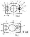
- Figure 1 shows an upper plan view of a current collector terminal in electric batteries carried out according to the object of the present invention.
- Figure 2 shows a view similar to that of the previous figure, in which the base body of the terminal is partially sectioned in order to show its inner structure.
- Figure 3 shows an elevational view of the terminal of the previous figures.
- Figure 4 shows a cross section view of the terminal according to section line A-A of Figure 3.
- Figure 5 shows another section view of a detail of the terminal, now according to section line B-B of Figure 1.
- Figure 6 finally shows a perspective view of the same terminal duly opposite to a post of the battery and with the fixing screw for fixing it to said post being disassembled.
- In view of the discussed figures, it can be seen how the terminal described is formed from an approximately rectangular prismatic base body (1), having a wide central hole (2) having a diameter in accordance with the diameter of the post (3) of the battery (4) it is intended for, but with the particularity that it is slightly divergent towards its inner face, i.e. it adopts a slightly frustoconical configuration so as to facilitate its coupling on the post (3).
- A considerably smaller side hole (5) opens radially towards the hole (2), the inner mouth of the side hole, the mouth of the opening towards the hole (2), being slightly narrowed and having a section close to its other threaded end, a ball (6) being housed inside this hole (5) which is able to partially penetrate the hole (2) pressed against by a spring (7) externally supported on a screw (8) threaded in the corresponding section of the hole (5).
- Evidently the spring (7) makes the ball (6) be supported on the post (3) of the battery when the terminal is coupled to said post, but the force for the mechanical fixing of the base body (1) to the post is carried out with the aid of a screw (9) having a conical front (10) located in a front threaded hole (11) of the base body (1), which opens towards the hole (5) in which the ball (6) is located, laterally acting on the latter and forcing it, along the inclined plane of its conical front (10), to penetrate the central hole (2) and to strongly press against the post (3), thus mechanically fixing the post and base body (1).
- The mentioned screw (9) having a conical tip (10) incorporates opposite to said tip a diametrical groove (12) for tightening it with a screwdriver, and furthermore the length of said screw is such that part of it is outside the base body (1) in a tightened situation, receiving a bracket (13) acting as a locknut so as to prevent the loosening of the screw (1) and, accordingly, the loosening in the tightness of the ball (6) against the post (3).
- Located on the opposite side of the base body (1) there is a transverse through hole (14) having a suitable diameter so as to allow the passage therethrough of the cable or group of cables to connect to the post (3), which cables are fixed with the aid of a set-screw (15) threaded in a hole (16) perpendicular to the hole (14) and opening towards the latter.
- A second threaded hole (17) similar and close to the previous hole (15) allows the entrance of any element for checking the state of the battery.
Claims (4)
- A current collector terminal in electric batteries, particularly for the connection of the cables in an automobile to the terminals of the corresponding battery, characterized in that it is formed from a solid metal base body having a general rectangular prismatic configuration, having a wide central hole dimensionally suitable for its coupling to the corresponding post of the battery, a side hole having a considerably smaller diameter, with a slightly narrowed inner mouth and a threaded outer mouth, opening towards said central hole, in which side hole there is a ball, a spring tending to project said ball towards the inside of the central hole, and an outer screw regulating the tension of the spring, with the particularity that a front threaded hole opens towards this side hole, in which front hole there is in turn a screw having a conical front laterally acting on the ball pressing it against the post of the battery when the former is housed in the central hole of the base body, to which post the cables of the vehicle are suitably fixed.
- A current collector terminal in electric batteries according to claim 1, characterized in that the screw having a conical front is oversized in length in relation to the threaded hole it is coupled to such that it substantially projects to the outside where it receives a bracket acting as a locknut preventing the loosening of said screw.
- A current collector terminal in electric batteries according to the previous claims, characterized in that the wide central hole of the base body is slightly frustoconical, diverging towards its lower or rear face, so as to facilitate its coupling to the post of the battery.
- A current collector terminal in electric batteries, according to the previous claims characterized in that the base body incorporates, preferably in the area opposite to the location of the ball and its accessories, a transverse through hole suitable for internally receiving the cable or group of cables to connect to the corresponding post of the battery, which are fixed with the aid of a set-screw located in a front threaded hole which opens towards the mentioned through hole, the existence of a second threaded hole having been provided close and similar to the previous one for introducing elements for testing the state of the battery.
Applications Claiming Priority (1)
| Application Number | Priority Date | Filing Date | Title |
|---|---|---|---|
| ES200602206U ES1063912Y (en) | 2006-10-10 | 2006-10-10 | TERMINAL FOR POWER OUTLET IN ELECTRICAL BATTERIES. |
Publications (2)
| Publication Number | Publication Date |
|---|---|
| EP1909360A1 true EP1909360A1 (en) | 2008-04-09 |
| EP1909360B1 EP1909360B1 (en) | 2009-11-25 |
Family
ID=37814021
Family Applications (1)
| Application Number | Title | Priority Date | Filing Date |
|---|---|---|---|
| EP07380095A Active EP1909360B1 (en) | 2006-10-10 | 2007-04-11 | Current collector terminal in electric batteries |
Country Status (4)
| Country | Link |
|---|---|
| EP (1) | EP1909360B1 (en) |
| AT (1) | ATE450065T1 (en) |
| DE (1) | DE602007003418D1 (en) |
| ES (2) | ES1063912Y (en) |
Citations (4)
| Publication number | Priority date | Publication date | Assignee | Title |
|---|---|---|---|---|
| GB231923A (en) * | 1923-12-13 | 1925-04-14 | Rudolf Woods | Improvements in sockets or holders for the thermionic valves of wireless systems and apparatus for telephony and telegraphy |
| US3678450A (en) * | 1971-03-31 | 1972-07-18 | Eugene C Azamber | Battery connector |
| EP0381996A2 (en) * | 1989-02-10 | 1990-08-16 | Balzers Aktiengesellschaft | Ion generating device |
| DE4404057A1 (en) * | 1994-02-09 | 1995-08-10 | Eifelwerk Heinrich Stein Gmbh | Electrical terminal connector clamp |
-
2006
- 2006-10-10 ES ES200602206U patent/ES1063912Y/en not_active Expired - Fee Related
-
2007
- 2007-04-11 ES ES07380095T patent/ES2336268T3/en active Active
- 2007-04-11 DE DE602007003418T patent/DE602007003418D1/en active Active
- 2007-04-11 EP EP07380095A patent/EP1909360B1/en active Active
- 2007-04-11 AT AT07380095T patent/ATE450065T1/en not_active IP Right Cessation
Patent Citations (4)
| Publication number | Priority date | Publication date | Assignee | Title |
|---|---|---|---|---|
| GB231923A (en) * | 1923-12-13 | 1925-04-14 | Rudolf Woods | Improvements in sockets or holders for the thermionic valves of wireless systems and apparatus for telephony and telegraphy |
| US3678450A (en) * | 1971-03-31 | 1972-07-18 | Eugene C Azamber | Battery connector |
| EP0381996A2 (en) * | 1989-02-10 | 1990-08-16 | Balzers Aktiengesellschaft | Ion generating device |
| DE4404057A1 (en) * | 1994-02-09 | 1995-08-10 | Eifelwerk Heinrich Stein Gmbh | Electrical terminal connector clamp |
Also Published As
| Publication number | Publication date |
|---|---|
| ES2336268T3 (en) | 2010-04-09 |
| ES1063912Y (en) | 2007-03-16 |
| DE602007003418D1 (en) | 2010-01-07 |
| EP1909360B1 (en) | 2009-11-25 |
| ATE450065T1 (en) | 2009-12-15 |
| ES1063912U (en) | 2006-12-16 |
Similar Documents
| Publication | Publication Date | Title |
|---|---|---|
| EP1204165B1 (en) | A battery terminal provided with a current sensor | |
| CN100553034C (en) | Antenna Mounting Device | |
| US7794265B2 (en) | Battery post electrical terminal assembly | |
| US5620291A (en) | Quick disconnect fastener | |
| US6808841B2 (en) | Battery terminal unit provided with a current sensor | |
| CN101669253A (en) | Terminal point for connecting a ring terminal to an electrical device | |
| US7749030B1 (en) | Battery terminal-cable connector | |
| US7303448B1 (en) | Battery terminal connector with reversible clamp lever | |
| US6459233B1 (en) | Cable attachment assembly for battery of vehicle | |
| WO2018047116A1 (en) | Battery terminal connector | |
| US3230499A (en) | Battery clamp connectors | |
| US5013259A (en) | Remote auxiliary terminal assembly | |
| JPH05109399A (en) | Method and apparatus for linking battery cable | |
| JP2007214068A (en) | Battery terminal with current sensor | |
| US20040115999A1 (en) | Quick connect battery terminal | |
| EP1909360B1 (en) | Current collector terminal in electric batteries | |
| GB2374986A (en) | Cable connections for battery terminal | |
| JPH1092484A (en) | Connection terminal fixing structure | |
| US20250023293A1 (en) | Connector assembly and method of assembling such a connector assembly | |
| KR20080005285U (en) | Jig for wire harness with clamp | |
| CA2947555C (en) | Clamp for affixing an electrical wire to an electrically conductive post | |
| JP2010033919A (en) | Battery terminal | |
| US6857914B1 (en) | Battery post connector apparatus | |
| US20060024994A1 (en) | Clamp device for long component | |
| US20070134997A1 (en) | Side entry terminal pin |
Legal Events
| Date | Code | Title | Description |
|---|---|---|---|
| PUAI | Public reference made under article 153(3) epc to a published international application that has entered the european phase |
Free format text: ORIGINAL CODE: 0009012 |
|
| 17P | Request for examination filed |
Effective date: 20070412 |
|
| AK | Designated contracting states |
Kind code of ref document: A1 Designated state(s): AT BE BG CH CY CZ DE DK EE ES FI FR GB GR HU IE IS IT LI LT LU LV MC MT NL PL PT RO SE SI SK TR |
|
| AX | Request for extension of the european patent |
Extension state: AL BA HR MK RS |
|
| 17Q | First examination report despatched |
Effective date: 20081106 |
|
| AKX | Designation fees paid |
Designated state(s): AT BE BG CH CY CZ DE DK EE ES FI FR GB GR HU IE IS IT LI LT LU LV MC MT NL PL PT RO SE SI SK TR |
|
| GRAP | Despatch of communication of intention to grant a patent |
Free format text: ORIGINAL CODE: EPIDOSNIGR1 |
|
| GRAS | Grant fee paid |
Free format text: ORIGINAL CODE: EPIDOSNIGR3 |
|
| GRAA | (expected) grant |
Free format text: ORIGINAL CODE: 0009210 |
|
| AK | Designated contracting states |
Kind code of ref document: B1 Designated state(s): AT BE BG CH CY CZ DE DK EE ES FI FR GB GR HU IE IS IT LI LT LU LV MC MT NL PL PT RO SE SI SK TR |
|
| REG | Reference to a national code |
Ref country code: GB Ref legal event code: FG4D |
|
| REG | Reference to a national code |
Ref country code: CH Ref legal event code: EP |
|
| REG | Reference to a national code |
Ref country code: IE Ref legal event code: FG4D |
|
| REF | Corresponds to: |
Ref document number: 602007003418 Country of ref document: DE Date of ref document: 20100107 Kind code of ref document: P |
|
| REG | Reference to a national code |
Ref country code: NL Ref legal event code: VDEP Effective date: 20091125 |
|
| REG | Reference to a national code |
Ref country code: ES Ref legal event code: FG2A Ref document number: 2336268 Country of ref document: ES Kind code of ref document: T3 |
|
| LTIE | Lt: invalidation of european patent or patent extension |
Effective date: 20091125 |
|
| PG25 | Lapsed in a contracting state [announced via postgrant information from national office to epo] |
Ref country code: SE Free format text: LAPSE BECAUSE OF FAILURE TO SUBMIT A TRANSLATION OF THE DESCRIPTION OR TO PAY THE FEE WITHIN THE PRESCRIBED TIME-LIMIT Effective date: 20091125 Ref country code: IS Free format text: LAPSE BECAUSE OF FAILURE TO SUBMIT A TRANSLATION OF THE DESCRIPTION OR TO PAY THE FEE WITHIN THE PRESCRIBED TIME-LIMIT Effective date: 20100325 Ref country code: PT Free format text: LAPSE BECAUSE OF FAILURE TO SUBMIT A TRANSLATION OF THE DESCRIPTION OR TO PAY THE FEE WITHIN THE PRESCRIBED TIME-LIMIT Effective date: 20100325 Ref country code: LT Free format text: LAPSE BECAUSE OF FAILURE TO SUBMIT A TRANSLATION OF THE DESCRIPTION OR TO PAY THE FEE WITHIN THE PRESCRIBED TIME-LIMIT Effective date: 20091125 Ref country code: FI Free format text: LAPSE BECAUSE OF FAILURE TO SUBMIT A TRANSLATION OF THE DESCRIPTION OR TO PAY THE FEE WITHIN THE PRESCRIBED TIME-LIMIT Effective date: 20091125 |
|
| PG25 | Lapsed in a contracting state [announced via postgrant information from national office to epo] |
Ref country code: SI Free format text: LAPSE BECAUSE OF FAILURE TO SUBMIT A TRANSLATION OF THE DESCRIPTION OR TO PAY THE FEE WITHIN THE PRESCRIBED TIME-LIMIT Effective date: 20091125 Ref country code: CY Free format text: LAPSE BECAUSE OF FAILURE TO SUBMIT A TRANSLATION OF THE DESCRIPTION OR TO PAY THE FEE WITHIN THE PRESCRIBED TIME-LIMIT Effective date: 20091125 Ref country code: PL Free format text: LAPSE BECAUSE OF FAILURE TO SUBMIT A TRANSLATION OF THE DESCRIPTION OR TO PAY THE FEE WITHIN THE PRESCRIBED TIME-LIMIT Effective date: 20091125 Ref country code: LV Free format text: LAPSE BECAUSE OF FAILURE TO SUBMIT A TRANSLATION OF THE DESCRIPTION OR TO PAY THE FEE WITHIN THE PRESCRIBED TIME-LIMIT Effective date: 20091125 |
|
| PG25 | Lapsed in a contracting state [announced via postgrant information from national office to epo] |
Ref country code: AT Free format text: LAPSE BECAUSE OF FAILURE TO SUBMIT A TRANSLATION OF THE DESCRIPTION OR TO PAY THE FEE WITHIN THE PRESCRIBED TIME-LIMIT Effective date: 20091125 Ref country code: BE Free format text: LAPSE BECAUSE OF FAILURE TO SUBMIT A TRANSLATION OF THE DESCRIPTION OR TO PAY THE FEE WITHIN THE PRESCRIBED TIME-LIMIT Effective date: 20091125 |
|
| PG25 | Lapsed in a contracting state [announced via postgrant information from national office to epo] |
Ref country code: BG Free format text: LAPSE BECAUSE OF FAILURE TO SUBMIT A TRANSLATION OF THE DESCRIPTION OR TO PAY THE FEE WITHIN THE PRESCRIBED TIME-LIMIT Effective date: 20100225 Ref country code: DK Free format text: LAPSE BECAUSE OF FAILURE TO SUBMIT A TRANSLATION OF THE DESCRIPTION OR TO PAY THE FEE WITHIN THE PRESCRIBED TIME-LIMIT Effective date: 20091125 Ref country code: NL Free format text: LAPSE BECAUSE OF FAILURE TO SUBMIT A TRANSLATION OF THE DESCRIPTION OR TO PAY THE FEE WITHIN THE PRESCRIBED TIME-LIMIT Effective date: 20091125 Ref country code: RO Free format text: LAPSE BECAUSE OF FAILURE TO SUBMIT A TRANSLATION OF THE DESCRIPTION OR TO PAY THE FEE WITHIN THE PRESCRIBED TIME-LIMIT Effective date: 20091125 Ref country code: EE Free format text: LAPSE BECAUSE OF FAILURE TO SUBMIT A TRANSLATION OF THE DESCRIPTION OR TO PAY THE FEE WITHIN THE PRESCRIBED TIME-LIMIT Effective date: 20091125 |
|
| PGFP | Annual fee paid to national office [announced via postgrant information from national office to epo] |
Ref country code: FR Payment date: 20100428 Year of fee payment: 4 |
|
| PG25 | Lapsed in a contracting state [announced via postgrant information from national office to epo] |
Ref country code: CZ Free format text: LAPSE BECAUSE OF FAILURE TO SUBMIT A TRANSLATION OF THE DESCRIPTION OR TO PAY THE FEE WITHIN THE PRESCRIBED TIME-LIMIT Effective date: 20091125 Ref country code: SK Free format text: LAPSE BECAUSE OF FAILURE TO SUBMIT A TRANSLATION OF THE DESCRIPTION OR TO PAY THE FEE WITHIN THE PRESCRIBED TIME-LIMIT Effective date: 20091125 |
|
| PGFP | Annual fee paid to national office [announced via postgrant information from national office to epo] |
Ref country code: DE Payment date: 20100423 Year of fee payment: 4 |
|
| PLBE | No opposition filed within time limit |
Free format text: ORIGINAL CODE: 0009261 |
|
| STAA | Information on the status of an ep patent application or granted ep patent |
Free format text: STATUS: NO OPPOSITION FILED WITHIN TIME LIMIT |
|
| PG25 | Lapsed in a contracting state [announced via postgrant information from national office to epo] |
Ref country code: GR Free format text: LAPSE BECAUSE OF FAILURE TO SUBMIT A TRANSLATION OF THE DESCRIPTION OR TO PAY THE FEE WITHIN THE PRESCRIBED TIME-LIMIT Effective date: 20100226 |
|
| 26N | No opposition filed |
Effective date: 20100826 |
|
| PG25 | Lapsed in a contracting state [announced via postgrant information from national office to epo] |
Ref country code: MC Free format text: LAPSE BECAUSE OF NON-PAYMENT OF DUE FEES Effective date: 20100430 |
|
| PG25 | Lapsed in a contracting state [announced via postgrant information from national office to epo] |
Ref country code: IE Free format text: LAPSE BECAUSE OF NON-PAYMENT OF DUE FEES Effective date: 20100411 |
|
| PG25 | Lapsed in a contracting state [announced via postgrant information from national office to epo] |
Ref country code: MT Free format text: LAPSE BECAUSE OF FAILURE TO SUBMIT A TRANSLATION OF THE DESCRIPTION OR TO PAY THE FEE WITHIN THE PRESCRIBED TIME-LIMIT Effective date: 20091125 |
|
| REG | Reference to a national code |
Ref country code: CH Ref legal event code: PL |
|
| GBPC | Gb: european patent ceased through non-payment of renewal fee |
Effective date: 20110411 |
|
| PGFP | Annual fee paid to national office [announced via postgrant information from national office to epo] |
Ref country code: IT Payment date: 20100430 Year of fee payment: 4 |
|
| REG | Reference to a national code |
Ref country code: FR Ref legal event code: ST Effective date: 20111230 |
|
| PG25 | Lapsed in a contracting state [announced via postgrant information from national office to epo] |
Ref country code: CH Free format text: LAPSE BECAUSE OF NON-PAYMENT OF DUE FEES Effective date: 20110430 Ref country code: DE Free format text: LAPSE BECAUSE OF NON-PAYMENT OF DUE FEES Effective date: 20111101 Ref country code: FR Free format text: LAPSE BECAUSE OF NON-PAYMENT OF DUE FEES Effective date: 20110502 Ref country code: LI Free format text: LAPSE BECAUSE OF NON-PAYMENT OF DUE FEES Effective date: 20110430 |
|
| PG25 | Lapsed in a contracting state [announced via postgrant information from national office to epo] |
Ref country code: GB Free format text: LAPSE BECAUSE OF NON-PAYMENT OF DUE FEES Effective date: 20110411 |
|
| REG | Reference to a national code |
Ref country code: DE Ref legal event code: R119 Ref document number: 602007003418 Country of ref document: DE Effective date: 20111101 |
|
| PG25 | Lapsed in a contracting state [announced via postgrant information from national office to epo] |
Ref country code: HU Free format text: LAPSE BECAUSE OF FAILURE TO SUBMIT A TRANSLATION OF THE DESCRIPTION OR TO PAY THE FEE WITHIN THE PRESCRIBED TIME-LIMIT Effective date: 20100526 Ref country code: LU Free format text: LAPSE BECAUSE OF NON-PAYMENT OF DUE FEES Effective date: 20100411 |
|
| PG25 | Lapsed in a contracting state [announced via postgrant information from national office to epo] |
Ref country code: TR Free format text: LAPSE BECAUSE OF FAILURE TO SUBMIT A TRANSLATION OF THE DESCRIPTION OR TO PAY THE FEE WITHIN THE PRESCRIBED TIME-LIMIT Effective date: 20091125 |
|
| PGFP | Annual fee paid to national office [announced via postgrant information from national office to epo] |
Ref country code: ES Payment date: 20120510 Year of fee payment: 6 |
|
| REG | Reference to a national code |
Ref country code: ES Ref legal event code: FD2A Effective date: 20140606 |
|
| PG25 | Lapsed in a contracting state [announced via postgrant information from national office to epo] |
Ref country code: ES Free format text: LAPSE BECAUSE OF NON-PAYMENT OF DUE FEES Effective date: 20130412 |