EP1908922A2 - Device and method for hybrid vapor and film cooling of a turbine blade - Google Patents
Device and method for hybrid vapor and film cooling of a turbine blade Download PDFInfo
- Publication number
- EP1908922A2 EP1908922A2 EP07253811A EP07253811A EP1908922A2 EP 1908922 A2 EP1908922 A2 EP 1908922A2 EP 07253811 A EP07253811 A EP 07253811A EP 07253811 A EP07253811 A EP 07253811A EP 1908922 A2 EP1908922 A2 EP 1908922A2
- Authority
- EP
- European Patent Office
- Prior art keywords
- cooling
- airfoil
- vapor
- fluid
- subsystem
- Prior art date
- Legal status (The legal status is an assumption and is not a legal conclusion. Google has not performed a legal analysis and makes no representation as to the accuracy of the status listed.)
- Granted
Links
- 238000001816 cooling Methods 0.000 title claims abstract description 104
- 238000000034 method Methods 0.000 title description 4
- 238000009834 vaporization Methods 0.000 claims abstract description 26
- 230000008016 vaporization Effects 0.000 claims abstract description 26
- 239000012530 fluid Substances 0.000 claims description 30
- 238000006243 chemical reaction Methods 0.000 claims description 10
- 239000012809 cooling fluid Substances 0.000 claims 1
- 238000007599 discharging Methods 0.000 claims 1
- 239000006200 vaporizer Substances 0.000 claims 1
- 239000007789 gas Substances 0.000 description 14
- 239000007788 liquid Substances 0.000 description 9
- 239000000446 fuel Substances 0.000 description 3
- 238000009835 boiling Methods 0.000 description 2
- 238000002156 mixing Methods 0.000 description 2
- 230000000717 retained effect Effects 0.000 description 2
- 230000015556 catabolic process Effects 0.000 description 1
- 238000006731 degradation reaction Methods 0.000 description 1
- 230000000694 effects Effects 0.000 description 1
- 239000000463 material Substances 0.000 description 1
- 238000002844 melting Methods 0.000 description 1
- 230000008018 melting Effects 0.000 description 1
Images


Classifications
-
- F—MECHANICAL ENGINEERING; LIGHTING; HEATING; WEAPONS; BLASTING
- F01—MACHINES OR ENGINES IN GENERAL; ENGINE PLANTS IN GENERAL; STEAM ENGINES
- F01D—NON-POSITIVE DISPLACEMENT MACHINES OR ENGINES, e.g. STEAM TURBINES
- F01D5/00—Blades; Blade-carrying members; Heating, heat-insulating, cooling or antivibration means on the blades or the members
- F01D5/02—Blade-carrying members, e.g. rotors
- F01D5/08—Heating, heat-insulating or cooling means
- F01D5/081—Cooling fluid being directed on the side of the rotor disc or at the roots of the blades
- F01D5/082—Cooling fluid being directed on the side of the rotor disc or at the roots of the blades on the side of the rotor disc
-
- F—MECHANICAL ENGINEERING; LIGHTING; HEATING; WEAPONS; BLASTING
- F01—MACHINES OR ENGINES IN GENERAL; ENGINE PLANTS IN GENERAL; STEAM ENGINES
- F01D—NON-POSITIVE DISPLACEMENT MACHINES OR ENGINES, e.g. STEAM TURBINES
- F01D5/00—Blades; Blade-carrying members; Heating, heat-insulating, cooling or antivibration means on the blades or the members
- F01D5/12—Blades
- F01D5/14—Form or construction
- F01D5/18—Hollow blades, i.e. blades with cooling or heating channels or cavities; Heating, heat-insulating or cooling means on blades
-
- F—MECHANICAL ENGINEERING; LIGHTING; HEATING; WEAPONS; BLASTING
- F01—MACHINES OR ENGINES IN GENERAL; ENGINE PLANTS IN GENERAL; STEAM ENGINES
- F01D—NON-POSITIVE DISPLACEMENT MACHINES OR ENGINES, e.g. STEAM TURBINES
- F01D5/00—Blades; Blade-carrying members; Heating, heat-insulating, cooling or antivibration means on the blades or the members
- F01D5/12—Blades
- F01D5/14—Form or construction
- F01D5/18—Hollow blades, i.e. blades with cooling or heating channels or cavities; Heating, heat-insulating or cooling means on blades
- F01D5/181—Blades having a closed internal cavity containing a cooling medium, e.g. sodium
-
- F—MECHANICAL ENGINEERING; LIGHTING; HEATING; WEAPONS; BLASTING
- F01—MACHINES OR ENGINES IN GENERAL; ENGINE PLANTS IN GENERAL; STEAM ENGINES
- F01D—NON-POSITIVE DISPLACEMENT MACHINES OR ENGINES, e.g. STEAM TURBINES
- F01D5/00—Blades; Blade-carrying members; Heating, heat-insulating, cooling or antivibration means on the blades or the members
- F01D5/12—Blades
- F01D5/14—Form or construction
- F01D5/18—Hollow blades, i.e. blades with cooling or heating channels or cavities; Heating, heat-insulating or cooling means on blades
- F01D5/187—Convection cooling
-
- F—MECHANICAL ENGINEERING; LIGHTING; HEATING; WEAPONS; BLASTING
- F01—MACHINES OR ENGINES IN GENERAL; ENGINE PLANTS IN GENERAL; STEAM ENGINES
- F01D—NON-POSITIVE DISPLACEMENT MACHINES OR ENGINES, e.g. STEAM TURBINES
- F01D5/00—Blades; Blade-carrying members; Heating, heat-insulating, cooling or antivibration means on the blades or the members
- F01D5/30—Fixing blades to rotors; Blade roots ; Blade spacers
- F01D5/3007—Fixing blades to rotors; Blade roots ; Blade spacers of axial insertion type
-
- F—MECHANICAL ENGINEERING; LIGHTING; HEATING; WEAPONS; BLASTING
- F05—INDEXING SCHEMES RELATING TO ENGINES OR PUMPS IN VARIOUS SUBCLASSES OF CLASSES F01-F04
- F05D—INDEXING SCHEME FOR ASPECTS RELATING TO NON-POSITIVE-DISPLACEMENT MACHINES OR ENGINES, GAS-TURBINES OR JET-PROPULSION PLANTS
- F05D2260/00—Function
- F05D2260/20—Heat transfer, e.g. cooling
- F05D2260/202—Heat transfer, e.g. cooling by film cooling
-
- F—MECHANICAL ENGINEERING; LIGHTING; HEATING; WEAPONS; BLASTING
- F05—INDEXING SCHEMES RELATING TO ENGINES OR PUMPS IN VARIOUS SUBCLASSES OF CLASSES F01-F04
- F05D—INDEXING SCHEME FOR ASPECTS RELATING TO NON-POSITIVE-DISPLACEMENT MACHINES OR ENGINES, GAS-TURBINES OR JET-PROPULSION PLANTS
- F05D2260/00—Function
- F05D2260/20—Heat transfer, e.g. cooling
- F05D2260/205—Cooling fluid recirculation, i.e. after cooling one or more components is the cooling fluid recovered and used elsewhere for other purposes
-
- F—MECHANICAL ENGINEERING; LIGHTING; HEATING; WEAPONS; BLASTING
- F05—INDEXING SCHEMES RELATING TO ENGINES OR PUMPS IN VARIOUS SUBCLASSES OF CLASSES F01-F04
- F05D—INDEXING SCHEME FOR ASPECTS RELATING TO NON-POSITIVE-DISPLACEMENT MACHINES OR ENGINES, GAS-TURBINES OR JET-PROPULSION PLANTS
- F05D2260/00—Function
- F05D2260/20—Heat transfer, e.g. cooling
- F05D2260/207—Heat transfer, e.g. cooling using a phase changing mass, e.g. heat absorbing by melting or boiling
-
- F—MECHANICAL ENGINEERING; LIGHTING; HEATING; WEAPONS; BLASTING
- F05—INDEXING SCHEMES RELATING TO ENGINES OR PUMPS IN VARIOUS SUBCLASSES OF CLASSES F01-F04
- F05D—INDEXING SCHEME FOR ASPECTS RELATING TO NON-POSITIVE-DISPLACEMENT MACHINES OR ENGINES, GAS-TURBINES OR JET-PROPULSION PLANTS
- F05D2260/00—Function
- F05D2260/20—Heat transfer, e.g. cooling
- F05D2260/221—Improvement of heat transfer
- F05D2260/2214—Improvement of heat transfer by increasing the heat transfer surface
- F05D2260/22141—Improvement of heat transfer by increasing the heat transfer surface using fins or ribs
Definitions
- the present invention relates to cooling systems for fluid reaction devices for gas turbine engines.
- Vapor cooling systems (synonymously called evaporative cooling systems) have been proposed as a way to cool fluid reaction devices in gas turbine engines, such as turbine blades and vanes. In general, these vapor cooling systems include sealed internal cavities and passageways that form a vaporization section and a condenser section.
- a liquid is distributed to the vaporization section, which is located in a portion of the blade or vane that is exposed to high temperatures (typically the airfoil portion).
- the liquid absorbs thermal energy and is converted to a gas as the liquid surpasses its boiling point.
- the gas moves through the sealed cavities and passageways to the condenser section, where thermal energy is removed and the gas is converted back to a liquid.
- Thermal energy is typically removed from the condenser section of the vapor cooling system by passing engine bleed air along exterior surfaces of the condenser section. The liquid from the condenser section is then returned to the vaporization section, and the process can begin again.
- vapor cooling systems are ineffective in cooling the trailing edges of the airfoils of turbine blades or vanes.
- Vaporization chambers for a hot airfoil section of a turbine blade or vane require internal passageways that take up significant space.
- the trailing edges of airfoils are thin sections that do not provide adequate space for internal vaporization section structures and passageways. Normally, this would mean that only a leading edge portion of the airfoil would be vapor cooled, while the trailing edge would remain uncooled.
- inadequate trailing edge cooling is undesirable and may prevent the practical application of vapor cooling in gas turbine engines.
- increasing the cooling of the leading edge portion to indirectly cool the trailing edge can result in over-cooling of the leading edge of the blade or vane, which can reduce engine performance undesirably.
- vapor cooling systems typically cool the condenser, which is typically located within a root portion of the cooled blade or vane, by passing engine bleed air around it.
- known vapor cooling systems do not provide for an efficient exhaust path for the "spent" bleed air that has absorbed thermal energy from the condenser. Spent bleed air allowed to seep into the primary airflow at an angle can cause undesired mixing loss, which reduces engine power efficiency and fuel efficiency.
- An apparatus for a gas turbine engine includes an airfoil defining a leading edge and a trailing edge, a root located adjacent to the airfoil, a vapor cooling system, and a film cooling system for cooling the airfoil in conjunction with the vapor cooling system.
- the vapor cooling system includes a vaporization section located within the airfoil and a condenser section located within the root.
- the present invention provides a hybrid cooling system that can provide vapor cooling (synonymously called evaporative cooling) to a leading edge portion of an airfoil of a turbine blade or vane along with film cooling to a trailing edge portion of the airfoil.
- vapor cooling spindle cooling
- film cooling subsystem which exhausts the air into a primary engine flowpath in an efficient manner.
- FIG. 1 is a perspective view of a portion of a turbine blade 20 for a gas turbine engine.
- the blade 20 includes an airfoil 22 (in the interest of simplicity, only a portion of the airfoil 22 is shown in FIG. 1, and the internal structures of the airfoil 22 are not shown in cross section), a platform 24, and a root portion 26.
- the airfoil 22 is an aerodynamically shaped fluid reaction member that extends outward from the platform 24 and is positionable within a flowpath of the engine to perform work with respect to fluid moving along the flowpath.
- the airfoil 22 defines a leading edge 28, a trailing edge 30, a pressure side 32 and a suction side 34 (not visible in FIG. 1).
- a vaporization chamber 36 is located inside the airfoil 22 at its leading edge 28.
- a number of film cooling openings 38 are located at the trailing edge 30 of the airfoil 22.
- the openings 38 are slots similar to known film cooling slots for gas turbine airfoils. The total number of openings 38 will vary depending upon the desired amount of film cooling.
- the particular configuration of the airfoil 22 as shown in FIG. 1 is merely exemplary. It should be understood that the particular configuration of the airfoil 22 and other structures of the blade 20 will vary according to the desired application.
- the root portion 26 forms a dovetail shape (e.g., a single lug shape, fir tree shape, etc.) for retaining the blade 20 in a corresponding slot (not shown) in a conventional manner.
- the root portion 26 of the blade 20 is configured to be retained in an axially oriented slot formed in an outer rim of a rotor disk (not shown).
- the root portion 26 also contains a condenser 40 that is linked to the vaporization chamber 36. Airflow 42 can be directed along the exterior of the condenser 40 to remove thermal energy, as will be explained in greater detail below.
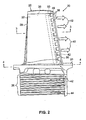
- FIG. 2 is a side view of the turbine blade 20.
- FIG. 3 is a cross-sectional view of the turbine blade 20 taken along line 3-3 of FIG. 2
- FIG. 4 is a cross-sectional view of the turbine blade 20 taken along line 4-4 of FIG. 2.
- an optional flow deflector 44 is located at an aft end of the blade root 26.
- the flow deflector 44 can have a scoop-like shape that extends beyond the inner end of the root 26 in manner similar to the flow deflector disclosed in U.S. Pat. No. 6,974,306 by Djeridan et al .
- the flow deflector 44 redirects at least a portion of the airflow 42, and typically redirects most of the airflow 42 from a generally axial direction to a generally radially outward direction. As shown in FIGS. 3 and 4, the redirected airflow 42 can then flow through an internal passageway 46 through the root portion 26 and the platform 24 to an airflow chamber 48 inside the airfoil 22.
- the openings 38 extend to the airflow chamber 48, such that airflow 42 can pass out of the airflow chamber 48 through the openings 38 to provide film cooling to the thin portion of the airfoil 22 at the trailing edge 30 in a conventional manner.
- the film cooling process is explained further below.
- the airflow chamber 48 is located at or near the trailing edge 30 of the airfoil 22, and the vaporization section 36 is located at or near the leading edge 28 of the airfoil 22.
- An internal wall 50 is defined by the airfoil 22 between the airflow chamber 48 and the vaporization chamber 36.
- the wall 50 can be about 30 mil (0.76 mm) in an axial direction. The location and precise dimensions of the wall 50 will be determined as function of the heat load on the blade 20 in a particular application. Likewise, the relative sizes and configurations of the vaporization chamber 36 and the airflow chamber 48 will also be determined as function of heat loading.
- the vaporization chamber 36 and the condenser 40 form a vapor cooling subsystem that provides cooling to a portion of the airfoil 22 at or near the leading edge 28.
- the vaporization chamber 36 is shown in a simplified form.
- the vaporization chamber 36 can be configured in any suitable manner.
- a fluid is contained within the vapor cooling subsystem, and can pass between the vaporization chamber 36 and the condenser 40. In a liquid state, the fluid is distributed to the vaporization chamber 36, where the liquid fluid absorbs thermal energy and is converted to a gaseous state when its boiling point is reached. The gaseous fluid then passes to the condenser 40, which removes thermal energy to convert the fluid back to the liquid state. The liquid fluid can then be returned to the vaporization chamber 36 and the process continued.
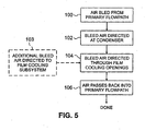
- FIG. 5 is a flow chart detailing steps performed to cool the turbine blade 20.
- the airfoil 22 is subjected to high temperature conditions as hot gases move through the primary flowpath of the engine in which the blade 20 is installed.
- the vaporization subsystem absorbs thermal energy with the fluid present in the vaporization chamber 36 and transfers that absorbed thermal energy to the condenser 40.
- air is bled from the primary flowpath (step 100), for example compressor bleed air is taken from a suitable compressor stage. At least some of the bleed air is then routed to the location of the blade 20 and directed at the exterior surfaces of the condenser 40 in airflow 42 (step 102).
- the bleed air is directed into a disk slot in which the root portion 26 is retained, allowing the airflow 42 to pass through one or more gaps between the disk slot and the condenser 40 in the root portion 40.
- the bleed air in the airflow 42 passes the condenser 40, the bleed air absorbs thermal energy from the fluid inside the condenser 40. At least some of the bleed air in the airflow 42 is then redirected by the flow deflector 44 and through the internal passageway 46. Some additional thermal energy can be absorbed by the bleed air while in the internal passageway 46. It is desired to redirect close to 100% of the bleed air into the passageway 46.
- additional bleed air not used to cool the condenser 40 can be introduced to the passageway 46 to bolster film cooling (step 103).
- the bleed air in the airflow 42 passes from the passageway 46 to the airflow chamber 48 and through the openings 38 at the trailing edge 30 of the airfoil 22 (step 104).
- the bleed air leaves the openings 38, it passes over the exterior surface of the airfoil 22 to provide film cooling in a conventional manner.
- the bleed air is exhausted into the engine's primary airflow in a direction that is generally parallel with the primary airflow (step 106).
- the hybrid cooling system of the present invention utilizes vapor cooling to cool a large portion of the airfoil 22 of the blade 20 at or near its leading edge 28. Film cooling is then used to cool a portion of the airfoil 22 at or near the trailing edge 30, which is difficult to cool using vapor cooling alone.
- the hybrid cooling system of the present invention allows a high degree of cooling to be provided to the blade 20, which can help improve the lifespan of the blade 20.
- hybrid cooling system of the present invention can be applied to a variety of gas turbine engine components, including nearly any type of blade or vane having an airfoil.
Landscapes
- Engineering & Computer Science (AREA)
- Mechanical Engineering (AREA)
- General Engineering & Computer Science (AREA)
- Turbine Rotor Nozzle Sealing (AREA)
Abstract
Description
- The present invention relates to cooling systems for fluid reaction devices for gas turbine engines.
- In order to operate a gas turbine engine at optimal conditions, temperatures in the hot region of the primary gas flowpath are often very high. High temperatures can have negative effects on engine components exposed to the primary flowpath, increasing risks for component degradation and failure. Indeed, temperatures at some points along the primary flowpath can exceed the melting points of materials used to form some engine components. For that reason, cooling systems are used to reduce damage and wear on engine components associated with high temperature conditions. Vapor cooling systems (synonymously called evaporative cooling systems) have been proposed as a way to cool fluid reaction devices in gas turbine engines, such as turbine blades and vanes. In general, these vapor cooling systems include sealed internal cavities and passageways that form a vaporization section and a condenser section. A liquid is distributed to the vaporization section, which is located in a portion of the blade or vane that is exposed to high temperatures (typically the airfoil portion). The liquid absorbs thermal energy and is converted to a gas as the liquid surpasses its boiling point. The gas moves through the sealed cavities and passageways to the condenser section, where thermal energy is removed and the gas is converted back to a liquid. Thermal energy is typically removed from the condenser section of the vapor cooling system by passing engine bleed air along exterior surfaces of the condenser section. The liquid from the condenser section is then returned to the vaporization section, and the process can begin again.
- Known designs present a number of problems that hinder and may prevent the effective implementation of a vapor cooling scheme in gas turbine engines. One such problem is that vapor cooling systems are ineffective in cooling the trailing edges of the airfoils of turbine blades or vanes. Vaporization chambers for a hot airfoil section of a turbine blade or vane require internal passageways that take up significant space. However, the trailing edges of airfoils are thin sections that do not provide adequate space for internal vaporization section structures and passageways. Normally, this would mean that only a leading edge portion of the airfoil would be vapor cooled, while the trailing edge would remain uncooled. However, inadequate trailing edge cooling is undesirable and may prevent the practical application of vapor cooling in gas turbine engines. Conversely, increasing the cooling of the leading edge portion to indirectly cool the trailing edge can result in over-cooling of the leading edge of the blade or vane, which can reduce engine performance undesirably.
- Furthermore, vapor cooling systems typically cool the condenser, which is typically located within a root portion of the cooled blade or vane, by passing engine bleed air around it. However, known vapor cooling systems do not provide for an efficient exhaust path for the "spent" bleed air that has absorbed thermal energy from the condenser. Spent bleed air allowed to seep into the primary airflow at an angle can cause undesired mixing loss, which reduces engine power efficiency and fuel efficiency.
- It is desired to provide a cooling system for a turbine blade or vane that utilizes vapor cooling of the airfoil while also providing adequate cooling to the airfoil trailing edge. It is further desired to provide an efficient exhaust route for spent air used to cool a condenser of a vapor cooling system for a turbine blade or vane.
- An apparatus for a gas turbine engine according to the present invention includes an airfoil defining a leading edge and a trailing edge, a root located adjacent to the airfoil, a vapor cooling system, and a film cooling system for cooling the airfoil in conjunction with the vapor cooling system. The vapor cooling system includes a vaporization section located within the airfoil and a condenser section located within the root.
-
- FIG. 1 is a perspective view of a portion of a turbine blade according to the present invention.
- FIG. 2 is a side view of the turbine blade of FIG. 1.
- FIG. 3 is a cross-sectional view of the turbine blade, taken along line 3-3 of FIG. 2.
- FIG. 4 is a cross-sectional view of the turbine blade, taken along line 4-4 of FIG. 2.
- FIG. 5 is a flow chart detailing steps performed to cool the turbine blade.
- In general, the present invention provides a hybrid cooling system that can provide vapor cooling (synonymously called evaporative cooling) to a leading edge portion of an airfoil of a turbine blade or vane along with film cooling to a trailing edge portion of the airfoil. Furthermore, air used to cool a condenser of a vapor cooling subsystem can be directed to a film cooling subsystem, which exhausts the air into a primary engine flowpath in an efficient manner.
- FIG. 1 is a perspective view of a portion of a
turbine blade 20 for a gas turbine engine. Theblade 20 includes an airfoil 22 (in the interest of simplicity, only a portion of theairfoil 22 is shown in FIG. 1, and the internal structures of theairfoil 22 are not shown in cross section), aplatform 24, and aroot portion 26. - The
airfoil 22 is an aerodynamically shaped fluid reaction member that extends outward from theplatform 24 and is positionable within a flowpath of the engine to perform work with respect to fluid moving along the flowpath. Theairfoil 22 defines a leadingedge 28, atrailing edge 30, apressure side 32 and a suction side 34 (not visible in FIG. 1). As will be explained further below, avaporization chamber 36 is located inside theairfoil 22 at its leadingedge 28. A number offilm cooling openings 38 are located at thetrailing edge 30 of theairfoil 22. Theopenings 38 are slots similar to known film cooling slots for gas turbine airfoils. The total number ofopenings 38 will vary depending upon the desired amount of film cooling. - The particular configuration of the
airfoil 22 as shown in FIG. 1 is merely exemplary. It should be understood that the particular configuration of theairfoil 22 and other structures of theblade 20 will vary according to the desired application. - The
root portion 26 forms a dovetail shape (e.g., a single lug shape, fir tree shape, etc.) for retaining theblade 20 in a corresponding slot (not shown) in a conventional manner. In the illustrated embodiment, theroot portion 26 of theblade 20 is configured to be retained in an axially oriented slot formed in an outer rim of a rotor disk (not shown). Theroot portion 26 also contains acondenser 40 that is linked to thevaporization chamber 36.Airflow 42 can be directed along the exterior of thecondenser 40 to remove thermal energy, as will be explained in greater detail below. - FIG. 2 is a side view of the
turbine blade 20. FIG. 3 is a cross-sectional view of theturbine blade 20 taken along line 3-3 of FIG. 2, and FIG. 4 is a cross-sectional view of theturbine blade 20 taken along line 4-4 of FIG. 2. As shown in FIG. 2, anoptional flow deflector 44 is located at an aft end of theblade root 26. Theflow deflector 44 can have a scoop-like shape that extends beyond the inner end of theroot 26 in manner similar to the flow deflector disclosed inU.S. Pat. No. 6,974,306 by Djeridan et al . Theflow deflector 44 redirects at least a portion of theairflow 42, and typically redirects most of theairflow 42 from a generally axial direction to a generally radially outward direction. As shown in FIGS. 3 and 4, the redirectedairflow 42 can then flow through aninternal passageway 46 through theroot portion 26 and theplatform 24 to anairflow chamber 48 inside theairfoil 22. Theopenings 38 extend to theairflow chamber 48, such thatairflow 42 can pass out of theairflow chamber 48 through theopenings 38 to provide film cooling to the thin portion of theairfoil 22 at thetrailing edge 30 in a conventional manner. The film cooling process is explained further below. - As shown in FIG. 3, the
airflow chamber 48 is located at or near thetrailing edge 30 of theairfoil 22, and thevaporization section 36 is located at or near the leadingedge 28 of theairfoil 22. Aninternal wall 50 is defined by theairfoil 22 between theairflow chamber 48 and thevaporization chamber 36. In one embodiment, thewall 50 can be about 30 mil (0.76 mm) in an axial direction. The location and precise dimensions of thewall 50 will be determined as function of the heat load on theblade 20 in a particular application. Likewise, the relative sizes and configurations of thevaporization chamber 36 and theairflow chamber 48 will also be determined as function of heat loading. - The
vaporization chamber 36 and thecondenser 40 form a vapor cooling subsystem that provides cooling to a portion of theairfoil 22 at or near the leadingedge 28. In the illustrated embodiment, thevaporization chamber 36 is shown in a simplified form. However, thevaporization chamber 36 can be configured in any suitable manner. A fluid is contained within the vapor cooling subsystem, and can pass between thevaporization chamber 36 and thecondenser 40. In a liquid state, the fluid is distributed to thevaporization chamber 36, where the liquid fluid absorbs thermal energy and is converted to a gaseous state when its boiling point is reached. The gaseous fluid then passes to thecondenser 40, which removes thermal energy to convert the fluid back to the liquid state. The liquid fluid can then be returned to thevaporization chamber 36 and the process continued. - In operation, the present invention provides cooling to the
blade 20. FIG. 5 is a flow chart detailing steps performed to cool theturbine blade 20. While in use, theairfoil 22 is subjected to high temperature conditions as hot gases move through the primary flowpath of the engine in which theblade 20 is installed. The vaporization subsystem absorbs thermal energy with the fluid present in thevaporization chamber 36 and transfers that absorbed thermal energy to thecondenser 40. At the same time, air is bled from the primary flowpath (step 100), for example compressor bleed air is taken from a suitable compressor stage. At least some of the bleed air is then routed to the location of theblade 20 and directed at the exterior surfaces of thecondenser 40 in airflow 42 (step 102). Typically, the bleed air is directed into a disk slot in which theroot portion 26 is retained, allowing theairflow 42 to pass through one or more gaps between the disk slot and thecondenser 40 in theroot portion 40. As the bleed air in theairflow 42 passes thecondenser 40, the bleed air absorbs thermal energy from the fluid inside thecondenser 40. At least some of the bleed air in theairflow 42 is then redirected by theflow deflector 44 and through theinternal passageway 46. Some additional thermal energy can be absorbed by the bleed air while in theinternal passageway 46. It is desired to redirect close to 100% of the bleed air into thepassageway 46. Optionally, additional bleed air not used to cool thecondenser 40 can be introduced to thepassageway 46 to bolster film cooling (step 103). Next, the bleed air in theairflow 42 passes from thepassageway 46 to theairflow chamber 48 and through theopenings 38 at the trailingedge 30 of the airfoil 22 (step 104). As the bleed air leaves theopenings 38, it passes over the exterior surface of theairfoil 22 to provide film cooling in a conventional manner. After leaving theopenings 38, the bleed air is exhausted into the engine's primary airflow in a direction that is generally parallel with the primary airflow (step 106). In this way, the hybrid cooling system of the present invention utilizes vapor cooling to cool a large portion of theairfoil 22 of theblade 20 at or near its leadingedge 28. Film cooling is then used to cool a portion of theairfoil 22 at or near the trailingedge 30, which is difficult to cool using vapor cooling alone. - By using the same bleed air to both cool the
condenser 40 and to provide film cooling through theopenings 38, it is possible to return almost all of the bleed air used for cooling theblade 20 to the primary flowpath. Furthermore, by exhausting bleed air generally parallel to the primary flowpath, mixing loss is reduced. These factors help promote engine power efficiency and fuel efficiency, and facilitate thrust-specific fuel consumption (TSFC). In addition, the hybrid cooling system of the present invention allows a high degree of cooling to be provided to theblade 20, which can help improve the lifespan of theblade 20. - Although the present invention has been described with reference to preferred embodiments, workers skilled in the art will recognize that changes may be made in form and detail without departing from the scope of the invention. For instance, the hybrid cooling system of the present invention can be applied to a variety of gas turbine engine components, including nearly any type of blade or vane having an airfoil.
Claims (24)
- An apparatus for a gas turbine engine, the apparatus comprising:an airfoil (22) defining a leading edge (28) and a trailing edge (30);a root (26) located adjacent to the airfoil (22);a vapor cooling system having a vaporization section (36) located within the airfoil (22) and a condenser section (40) located within the root (26); anda film cooling system (38) for cooling the airfoil (22) in conjunction with the vapor cooling system.
- The apparatus of claim 1, wherein vaporization section (36) within the airfoil (22) is located at or near the leading edge (28) of the airfoil (22).
- The apparatus of claim 1 or 2, wherein the film cooling system (38) is configured to provide a cooling film at or near the trailing edge (30) of the airfoil (22).
- The apparatus of any preceding claim wherein the film cooling system comprises:a plurality of openings (38) located at or near the trailing edge (30) of the airfoil (22); anda cooling fluid supply duct (46) in fluid communication with an inlet defined at the root (26) and each of the openings (38) located at or near the trailing edge (30) of the airfoil (22).
- The apparatus of claim 4 and further comprising:a flow deflector (44) extending from the root (26) for directing fluid into the film cooling system.
- The apparatus of claim 5, wherein the flow deflector (44) directs fluid used to cool the condenser section (40) of the vapor cooling system into the film cooling system (38).
- The apparatus of claim 4, 5 or 6, wherein the openings (38) are each slot-shaped.
- The apparatus of any preceding claim and further comprising:a wall (50) defined by a portion of the airfoil (22), wherein the wall (50) separates the vapor cooling system and the film cooling system.
- A cooling system for cooling a fluid reaction apparatus (20) of a gas turbine engine, the system comprising:a vapor cooling subsystem having a vaporization section (36) and a condenser section (40) for cooling a portion of the fluid reaction apparatus, wherein the condenser section (40) is cooled by a fluid; anda film cooling subsystem for cooling a portion of the fluid reaction apparatus (20) by discharging fluid out of openings (38) defined in the fluid reaction apparatus (20), wherein at least a portion of the fluid used to cool the condenser section (40) of the vapor cooling subsystem is discharged out of the openings (38) of the film cooling subsystem.
- The system of claim 9 and further comprising:a flow deflector (44) for directing the fluid used to cool the condenser (40) section to the film cooling subsystem.
- The system of claim 9 or 10, wherein the fluid reaction apparatus is a turbine blade (20).
- The system of claim 11, wherein the vapor cooling subsystem provides cooling to a leading edge portion (28) of the turbine blade (20).
- The system of claim 11 or 12, wherein the turbine blade (20) includes an airfoil (22) and a root (26), and wherein the vaporization section (36) of the vapor cooling subsystem is defined within the airfoil (22) and the condenser section (40) of the vapor cooling subsystem is defined within the root (26).
- The apparatus of any of claims 11 to 13, wherein the openings (38) defined in the fluid reaction apparatus are each slot-shaped.
- The apparatus of any of claims 11 to 14 and further comprising:a wall (50) defined by a portion of the fluid reaction apparatus, wherein the wall (50) separates the vaporization section (36) of the vapor cooling subsystem and the openings (38) of the film cooling subsystem.
- A hybrid cooling system for cooling a gas turbine engine component (20) having an airfoil portion (22) and a root portion (26), the system comprising:a first cooling subsystem for cooling a region at or near a leading edge (28) of the airfoil portion (22), wherein the first cooling subsystem utilizes vapor cooling; anda second cooling subsystem for cooling a region at or near a trailing edge (30) of the airfoil portion (22), wherein the second cooling subsystem utilizes film cooling.
- The system of claim 16, wherein the first cooling subsystem includes a vaporizer section (36) within the airfoil portion (22) and a condenser section (40) within the root portion (26).
- The system of claim 17, wherein the condenser section (40) is cooled by a fluid directed at the root portion (26).
- The system of claim 18, wherein the fluid directed at the root portion (26) to cool the condenser section (40) is subsequently directed through the second cooling subsystem.
- The system of claim 19, wherein the second cooling subsystem is configured to distribute at least a portion of the fluid into a primary flow path of the gas turbine engine.
- An improvement for a vapor cooled gas turbine engine component (20) having a leading edge (28) and a trailing edge (30), the improvement comprising:an auxiliary cooling system for cooling a region at or near the trailing edge (30) of gas turbine engine component (20) using film cooling.
- The improvement of claim 21, wherein the auxiliary cooling system comprises a film cooling system (38).
- The improvement of claim 21 or 22, wherein a vaporization section (36) of the vapor cooled gas turbine engine component (22) is separated from the auxiliary cooling system by an internal wall (50).
- The improvement of any of claims 21 to 23 and further comprising:a flow deflector (44) for redirecting a fluid used to cool a portion of a vapor cooling system of the vapor cooled gas turbine engine component (20) to the auxiliary cooling subsystem.
Applications Claiming Priority (1)
| Application Number | Priority Date | Filing Date | Title |
|---|---|---|---|
| US11/542,097 US7578652B2 (en) | 2006-10-03 | 2006-10-03 | Hybrid vapor and film cooled turbine blade |
Publications (3)
| Publication Number | Publication Date |
|---|---|
| EP1908922A2 true EP1908922A2 (en) | 2008-04-09 |
| EP1908922A3 EP1908922A3 (en) | 2010-05-05 |
| EP1908922B1 EP1908922B1 (en) | 2015-05-27 |
Family
ID=38658157
Family Applications (1)
| Application Number | Title | Priority Date | Filing Date |
|---|---|---|---|
| EP07253811.9A Active EP1908922B1 (en) | 2006-10-03 | 2007-09-26 | Apparatus for hybrid vapor and film cooling of a turbine blade |
Country Status (2)
| Country | Link |
|---|---|
| US (2) | US7578652B2 (en) |
| EP (1) | EP1908922B1 (en) |
Cited By (1)
| Publication number | Priority date | Publication date | Assignee | Title |
|---|---|---|---|---|
| EP3354851A1 (en) * | 2017-01-31 | 2018-08-01 | United Technologies Corporation | Hybrid airfoil cooling |
Families Citing this family (7)
| Publication number | Priority date | Publication date | Assignee | Title |
|---|---|---|---|---|
| US7578652B2 (en) * | 2006-10-03 | 2009-08-25 | United Technologies Corporation | Hybrid vapor and film cooled turbine blade |
| US8056345B2 (en) | 2007-06-13 | 2011-11-15 | United Technologies Corporation | Hybrid cooling of a gas turbine engine |
| EP2639407A1 (en) * | 2012-03-13 | 2013-09-18 | Siemens Aktiengesellschaft | Gas turbine arrangement alleviating stresses at turbine discs and corresponding gas turbine |
| US20160290234A1 (en) * | 2015-04-02 | 2016-10-06 | General Electric Company | Heat pipe temperature management system for wheels and buckets in a turbomachine |
| US20160290235A1 (en) * | 2015-04-02 | 2016-10-06 | General Electric Company | Heat pipe temperature management system for a turbomachine |
| US10309242B2 (en) * | 2016-08-10 | 2019-06-04 | General Electric Company | Ceramic matrix composite component cooling |
| CN115477002B (en) * | 2022-10-19 | 2025-08-15 | 中国民航大学 | Staged composite cooling structure and method for aircraft rudder |
Citations (3)
| Publication number | Priority date | Publication date | Assignee | Title |
|---|---|---|---|---|
| GB800517A (en) | 1955-11-28 | 1958-08-27 | Rolls Royce | Improvements in or relating to gas turbines |
| US3376918A (en) | 1965-08-02 | 1968-04-09 | Snecma | Cooling of turbine blades |
| GB2087980A (en) | 1980-11-20 | 1982-06-03 | Rolls Royce | Liquid cooled aerofoil for a gas turbine engine and a method of making the aerofoil |
Family Cites Families (20)
| Publication number | Priority date | Publication date | Assignee | Title |
|---|---|---|---|---|
| GB712112A (en) * | 1951-07-13 | 1954-07-21 | Bristol Aeroplane Co Ltd | Improvements in or relating to blade-locking means for turbine and the like rotor assemblies |
| US2708564A (en) * | 1952-02-29 | 1955-05-17 | Westinghouse Electric Corp | Turbine apparatus |
| US3287906A (en) | 1965-07-20 | 1966-11-29 | Gen Motors Corp | Cooled gas turbine vanes |
| US3334685A (en) * | 1965-08-18 | 1967-08-08 | Gen Electric | Fluid boiling and condensing heat transfer system |
| GB1516041A (en) | 1977-02-14 | 1978-06-28 | Secr Defence | Multistage axial flow compressor stators |
| GB2252368B (en) * | 1981-03-20 | 1993-02-17 | Rolls Royce | Liquid cooled aerofoil blade |
| GB2254379B (en) * | 1981-04-28 | 1993-04-14 | Rolls Royce | Cooled aerofoil blade |
| GB2254380B (en) * | 1981-06-05 | 1993-03-31 | Rolls Royce | Cooled aerofoil blade |
| US5634766A (en) * | 1994-08-23 | 1997-06-03 | General Electric Co. | Turbine stator vane segments having combined air and steam cooling circuits |
| US5857836A (en) * | 1996-09-10 | 1999-01-12 | Aerodyne Research, Inc. | Evaporatively cooled rotor for a gas turbine engine |
| JP3316415B2 (en) * | 1997-05-01 | 2002-08-19 | 三菱重工業株式会社 | Gas turbine cooling vane |
| US5975841A (en) | 1997-10-03 | 1999-11-02 | Thermal Corp. | Heat pipe cooling for turbine stators |
| FR2823794B1 (en) * | 2001-04-19 | 2003-07-11 | Snecma Moteurs | REPORTED AND COOLED DAWN FOR TURBINE |
| GB2389174B (en) * | 2002-05-01 | 2005-10-26 | Rolls Royce Plc | Cooling systems |
| US6974306B2 (en) * | 2003-07-28 | 2005-12-13 | Pratt & Whitney Canada Corp. | Blade inlet cooling flow deflector apparatus and method |
| CA2456563C (en) | 2004-01-30 | 2011-12-20 | Pratt & Whitney Canada Corp. | Anti-icing apparatus and method for aero-engine nose cone |
| US6988367B2 (en) * | 2004-04-20 | 2006-01-24 | Williams International Co. L.L.C. | Gas turbine engine cooling system and method |
| US7192245B2 (en) * | 2004-12-03 | 2007-03-20 | Pratt & Whitney Canada Corp. | Rotor assembly with cooling air deflectors and method |
| US20070022732A1 (en) * | 2005-06-22 | 2007-02-01 | General Electric Company | Methods and apparatus for operating gas turbine engines |
| US7578652B2 (en) * | 2006-10-03 | 2009-08-25 | United Technologies Corporation | Hybrid vapor and film cooled turbine blade |
-
2006
- 2006-10-03 US US11/542,097 patent/US7578652B2/en not_active Expired - Fee Related
-
2007
- 2007-09-26 EP EP07253811.9A patent/EP1908922B1/en active Active
-
2009
- 2009-07-14 US US12/502,727 patent/US9879543B2/en not_active Expired - Fee Related
Patent Citations (3)
| Publication number | Priority date | Publication date | Assignee | Title |
|---|---|---|---|---|
| GB800517A (en) | 1955-11-28 | 1958-08-27 | Rolls Royce | Improvements in or relating to gas turbines |
| US3376918A (en) | 1965-08-02 | 1968-04-09 | Snecma | Cooling of turbine blades |
| GB2087980A (en) | 1980-11-20 | 1982-06-03 | Rolls Royce | Liquid cooled aerofoil for a gas turbine engine and a method of making the aerofoil |
Cited By (2)
| Publication number | Priority date | Publication date | Assignee | Title |
|---|---|---|---|---|
| EP3354851A1 (en) * | 2017-01-31 | 2018-08-01 | United Technologies Corporation | Hybrid airfoil cooling |
| US10428660B2 (en) | 2017-01-31 | 2019-10-01 | United Technologies Corporation | Hybrid airfoil cooling |
Also Published As
| Publication number | Publication date |
|---|---|
| US7578652B2 (en) | 2009-08-25 |
| EP1908922A3 (en) | 2010-05-05 |
| US9879543B2 (en) | 2018-01-30 |
| EP1908922B1 (en) | 2015-05-27 |
| US20130142665A1 (en) | 2013-06-06 |
| US20080080980A1 (en) | 2008-04-03 |
Similar Documents
| Publication | Publication Date | Title |
|---|---|---|
| US9879543B2 (en) | Hybrid vapor and film cooled turbine blade | |
| CA2607878C (en) | Compound nozzle cooled engine | |
| US5711650A (en) | Gas turbine airfoil cooling | |
| US8172533B2 (en) | Turbine blade internal cooling configuration | |
| US8240981B2 (en) | Turbine airfoil with platform cooling | |
| EP1921272B1 (en) | Air-cooled aerofoil for a gas turbine engine | |
| US7632062B2 (en) | Turbine rotor blades | |
| EP1895099B1 (en) | Cascade tip baffle airfoil | |
| EP1231359B1 (en) | Method and apparatus for reducing turbine blade tip region temperatures | |
| EP1921292A2 (en) | Compound tubine cooled engine | |
| EP1956214A2 (en) | Vapour cooling system for a gas turbine engine | |
| US8740567B2 (en) | Reverse cavity blade for a gas turbine engine | |
| US20070071601A1 (en) | Cooled airfoil trailing edge tip exit | |
| US8641377B1 (en) | Industrial turbine blade with platform cooling | |
| EP2551458A2 (en) | Blade Cooling and Sealing System | |
| US20100239430A1 (en) | Coolable airfoil attachment section | |
| EP3647544B1 (en) | Cooled gas turbine guide vane airfoil | |
| US10329922B2 (en) | Gas turbine engine airfoil | |
| CN108779679B (en) | cooled turbine blades | |
| CN107091122B (en) | Turbine engine airfoil with cooling | |
| EP2631431B1 (en) | Aerofoil cooling arrangement | |
| EP3192972B1 (en) | Flow exchange baffle insert for a gas turbine engine component | |
| EP3578759A1 (en) | Airfoil and corresponding method of directing a cooling flow | |
| US11286788B2 (en) | Blade for a turbomachine turbine, comprising internal passages for circulating cooling air |
Legal Events
| Date | Code | Title | Description |
|---|---|---|---|
| PUAI | Public reference made under article 153(3) epc to a published international application that has entered the european phase |
Free format text: ORIGINAL CODE: 0009012 |
|
| AK | Designated contracting states |
Kind code of ref document: A2 Designated state(s): AT BE BG CH CY CZ DE DK EE ES FI FR GB GR HU IE IS IT LI LT LU LV MC MT NL PL PT RO SE SI SK TR |
|
| AX | Request for extension of the european patent |
Extension state: AL BA HR MK RS |
|
| PUAL | Search report despatched |
Free format text: ORIGINAL CODE: 0009013 |
|
| AK | Designated contracting states |
Kind code of ref document: A3 Designated state(s): AT BE BG CH CY CZ DE DK EE ES FI FR GB GR HU IE IS IT LI LT LU LV MC MT NL PL PT RO SE SI SK TR |
|
| AX | Request for extension of the european patent |
Extension state: AL BA HR MK RS |
|
| 17P | Request for examination filed |
Effective date: 20101029 |
|
| 17Q | First examination report despatched |
Effective date: 20101129 |
|
| AKX | Designation fees paid |
Designated state(s): DE GB |
|
| GRAP | Despatch of communication of intention to grant a patent |
Free format text: ORIGINAL CODE: EPIDOSNIGR1 |
|
| INTG | Intention to grant announced |
Effective date: 20150129 |
|
| GRAS | Grant fee paid |
Free format text: ORIGINAL CODE: EPIDOSNIGR3 |
|
| GRAA | (expected) grant |
Free format text: ORIGINAL CODE: 0009210 |
|
| AK | Designated contracting states |
Kind code of ref document: B1 Designated state(s): DE GB |
|
| REG | Reference to a national code |
Ref country code: GB Ref legal event code: FG4D |
|
| REG | Reference to a national code |
Ref country code: DE Ref legal event code: R096 Ref document number: 602007041561 Country of ref document: DE |
|
| REG | Reference to a national code |
Ref country code: DE Ref legal event code: R097 Ref document number: 602007041561 Country of ref document: DE |
|
| PLBE | No opposition filed within time limit |
Free format text: ORIGINAL CODE: 0009261 |
|
| STAA | Information on the status of an ep patent application or granted ep patent |
Free format text: STATUS: NO OPPOSITION FILED WITHIN TIME LIMIT |
|
| 26N | No opposition filed |
Effective date: 20160301 |
|
| REG | Reference to a national code |
Ref country code: DE Ref legal event code: R082 Ref document number: 602007041561 Country of ref document: DE Representative=s name: SCHMITT-NILSON SCHRAUD WAIBEL WOHLFROM PATENTA, DE |
|
| REG | Reference to a national code |
Ref country code: DE Ref legal event code: R082 Ref document number: 602007041561 Country of ref document: DE Representative=s name: SCHMITT-NILSON SCHRAUD WAIBEL WOHLFROM PATENTA, DE Ref country code: DE Ref legal event code: R081 Ref document number: 602007041561 Country of ref document: DE Owner name: UNITED TECHNOLOGIES CORP. (N.D.GES.D. STAATES , US Free format text: FORMER OWNER: UNITED TECHNOLOGIES CORP., HARTFORD, CONN., US |
|
| PGFP | Annual fee paid to national office [announced via postgrant information from national office to epo] |
Ref country code: DE Payment date: 20200819 Year of fee payment: 14 |
|
| REG | Reference to a national code |
Ref country code: DE Ref legal event code: R119 Ref document number: 602007041561 Country of ref document: DE |
|
| PG25 | Lapsed in a contracting state [announced via postgrant information from national office to epo] |
Ref country code: DE Free format text: LAPSE BECAUSE OF NON-PAYMENT OF DUE FEES Effective date: 20220401 |
|
| PGFP | Annual fee paid to national office [announced via postgrant information from national office to epo] |
Ref country code: GB Payment date: 20240820 Year of fee payment: 18 |